Article

Effect of W Contents and Annealing Temperatures on the Microstructure and Mechanical Properties of CoFeNi Medium Entropy Alloys

1
Engineering Research Center of Continuous Extrusion, Ministry of Education, Dalian Jiaotong University, Dalian 116028, China
2
Key Laboratory of Near-Net Forming of Light Metals of Liaoning Province, Dalian Jiaotong University, Dalian 116028, China
3
School of Materials Science and Engineering, Dalian Jiaotong University, Dalian 116028, China
4
Department of Materials Science and Engineering, Dalian Maritime University, Dalian 116026, China
*
Authors to whom correspondence should be addressed.
Metals 2025, 15(8), 854; https://doi.org/10.3390/met15080854
Submission received: 30 June 2025 / Revised: 23 July 2025 / Accepted: 24 July 2025 / Published: 30 July 2025

Abstract

In this work, the W element, with a larger atomic radius compared to Co, Fe, and Ni, was added to modify the microstructure and enhance the yield strength of CoFeNi medium entropy alloy (MEA). A detailed study was conducted to clarify the effects of W additions and annealing temperatures on the microstructure evolution and mechanical properties of CoFeNiWx (x = 0, 0.1, and 0.3) MEAs. CoFeNiW0.1 retained a single FCC structure without the formation of precipitates in the FCC phase, indicating that W, with a larger atomic radius, can completely dissolve in CoFeNiW0.1. For CoFeNiW0.3 MEA, coarse particles with an average diameter of ~2 μm appeared after homogenizing. Nevertheless, when the alloy was annealed at 800 °C and 900 °C, fine particles formed, with the average diameters of approximately 144 nm and 225 nm, respectively. After annealing at 800 °C, the CoFeNiW0.3 with a partially recrystallized microstructure exhibited better comprehensive mechanical properties.

1. Introductions

High entropy alloys (HEAs) and medium entropy alloys (MEAs), also known as multi-principal elements alloys, largely broaden the realm of alloy design and offer more choices for fabricating high-performance structural materials [1]. Yeh et al. pointed out that larger mixing entropy enabled HEAs and MEAs to exhibit a single-phase structure [2]. HEAs and MEAs with a single face-centered cubic (FCC) structure were widely studied due to their lower yield strength and excellent work hardening capacities [3,4,5]. CoFeNi with a single FCC structure can show a yield strength of ~180 MPa and an ultimate tensile strength of 442 MPa with an outstanding elongation of ~50% [6], indicating it is necessary to enhance the yield strength of this MEA.
L12-type coherent phase can significantly strengthen FCC-structured MEAs while preserving good ductility, which has become a research hotspot recently. CoFeNi MEAs strengthened by coherent L12 phase were reported in Ti/V, Ti, V, or Ti/Al-added CoFeNi alloy systems [6,7,8,9]. Wang et al. investigated L12-type (Ni, Co, Fe)3(Ti, V) nanoparticles reinforced CoFeNi MEA. The results suggested that (FeCoNi)84Ti8V8 can show a higher yield strength of ~950 MPa and an ultimate tensile strength of ~1394 MPa, while maintaining good ductility of ~25% [6]. L12-type Ni3Ti-strengthened CoFeNi was fabricated by alloying Ti, (FeCoNi)94Ti6 MEA exhibited an outstanding combination of mechanical properties, featuring a yield strength of 893 MPa, an ultimate tensile strength of 1263 MPa, and an elongation of 24% [7]. L12 phase, coherent with the disordered FCC phase, was found in (FeCoNi)80V20 MEA. This MEA displayed a yield strength of 600 MPa and had excellent work hardening capacity, leading to an ultimate tensile strength of 1100 MPa [8]. Yang et al. reported the coherent strengthening by the L12-type Ni3Al in (FeCoNi)86Al7Ti7 led to exceptional mechanical properties, including a yield strength of 1 GPa, an ultimate tensile strength of 1.5 GPa, and a tensile elongation of ~50% [9]. The aforementioned investigations have indicated L12-type coherent phase is effective in improving strength while maintaining good ductility. Nevertheless, the requirements for composition modulation are more stringent to avoid the detrimental brittle L21 phase [10].
Furthermore, Prof. C.T. Liu et al. previously demonstrated that the addition of refractory elements with larger atomic radius into the FCC lattice would induce lattice distortion. As a result of this, the lattice distortion energy can be produced, which would destabilize the FCC matrix and promote the appearance of a second phase [11]. W element with a larger atomic radius than transition elements, such as Co, Fe, and Ni, has been added to modify the microstructure and mechanical properties [12,13]. Chang et al. reported that doping 3 at.% W into CoCrNi led to an enhancement of yield strength of approximately 33% while maintaining good ductility [12]. By adding more W, μ phase appeared in CoCrNi MEA, causing the yield strength to increase from 427 MPa to 1356 MPa, with a good elongation of ~10%. The improvement of yield strength was attributed to enhanced grain refinement strengthening and precipitation strengthening [13]. Adding W into MEAs can display better mechanical properties, which can be an effective method to modify FCC-structured MEAs.
In this work, W was selected to be incorporated into FCC-type CoFeNi with varying contents. Meanwhile, a detail investigation was conducted to elucidate the effects of annealing temperatures on the microstructure evolution and mechanical properties of cold-rolled CoFeNiWx (x = 0, 0.1, and 0.3) MEAs. Our study could provide a better understanding of W-added MEAs and pave the way to achieve strength-ductility balance.

2. Experiment Methods

CoFeNiWx (x = 0, 0.1, and 0.3) MEAs were prepared by melting Co, Fe, Ni, and W pure metals with the purity of ≥99.9 wt.% using the arc-melting technique under Ti-gettered Ar atmosphere. The ingots were melted at least five times to ensure chemical uniformity, and then were cast into a Cu mold with the dimensions of ~60 mm × 11 mm × 5 mm. The obtained specimens were sealed in quartz tubes and homogenized at 1150 °C for 22 h, subsequently followed by water quenching, which was cold-rolled to a thickness reduction of ~70%. The samples taken from cold-rolled CoFeNiWx MEAs were sealed in quartz tubes and subsequently heat-treated at 700 °C, 800 °C, and 900 °C for 1 h, respectively, followed by water quenching.
The crystal structures of annealed CoFeNiWx (x = 0, 0.1, and 0.3) MEAs were analyzed by an Empyrean X-ray diffractometer (XRD, PANalytical B.V., Almelo, The Netherlands) at a range of 30°~100° with a step size of 0.039391°. The microstructure was characterized by a scanning electron microscope (SEM, Zeiss SUPRA 55, Oberkochen, Germany) under backscattered electron (BSE) mode, and a transmission electron microscope (TEM, JEOL JEM-2100F, Tokyo, Japan). The electron backscattered diffraction (EBSD) samples were prepared by mechanical polishing followed by ion etching (Gatan Ilion II 697, Pleasanton, CA, USA). In addition, the EBSD measurements were carried out by an EBSD detector (Oxford NordlysMax2, Oxford, UK) equipped on the SUPRA55 SEM. TEM samples were firstly ground to ~50 μm, then punched into disks with a diameter of 3 mm and finally thinned by ion milling (Gatan 695, Pleasanton, CA, USA). Dog-bone-shaped samples of ~1.5 mm × 12.5 mm × 3.2 mm were obtained by an electro-discharge cutting machine (Guangdong Datie Numerical Control Machinery Co., Ltd., DK350, Guangzhou, China). The obtained tensile samples were mechanical ground by SiC paper to remove oxide layers and tested at a strain rate of 1 × 10⁻³ s−1. An extensometer with a gauge length of 10 mm was used during the elastic deformation process.

3. Results

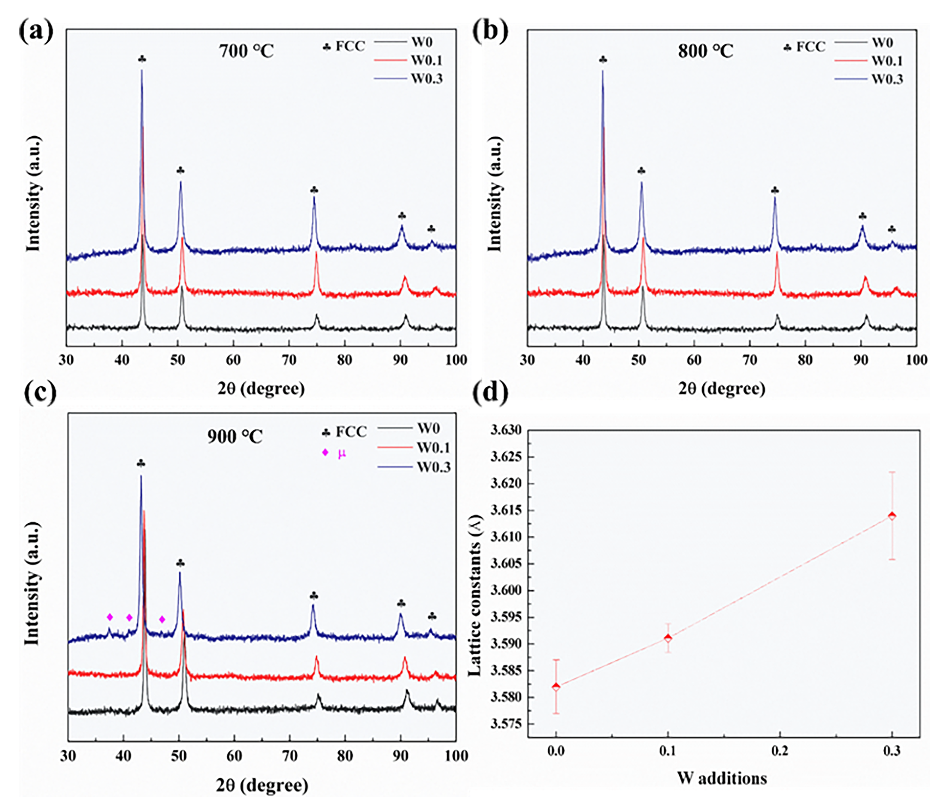
3.1. Crystal Structures

Figure 1 depicts the XRD patterns of cold-rolled CoFeNiWx (x = 0, 0.1, and 0.3) MEAs after annealing at 700 °C, 800 °C, and 900 °C for 1 h. The XRD patterns of as-cast CoFeNiWx (x = 0, 0.1, and 0.3) MEAs were also given in the Supplementary Material (as shown in Figure S1). As-cast CoFeNi and CoFeNiW0.1 exhibited a single FCC phase. After cold-rolling and annealing, a single FCC solid solution phase formed in CoFeNiWx (x = 0, 0.1) without observing obvious additional peaks in the XRD patterns. For x = 0.3, only FCC phase peaks were observed from the XRD pattern of as-cast CoFeNiW0.3 MEA (as depicted in Figure S1). After cold-rolling and annealing at 900 °C, these minor peaks appeared in CoFeNiW0.3 MEA, probably corresponding to Fe7W6-type μ phase (JCPDS card #20-0538) in additional to FCC phase peaks. Nevertheless, no obvious minor peaks can be found in CoFeNiW0.3 MEA after annealing at 700 °C and 800 °C, possibly because of the lower volume fraction of the intermetallic phase in the alloy. Moreover, the lattice constants (a) for CoFeNiWx alloys (as shown in Figure 1d) were calculated to be 3.5820 Å, 3.5911 Å, and 3.6140 Å, respectively, which increased with W additions due to the enhanced lattice distortions caused by W dissolutions into the FCC phase.

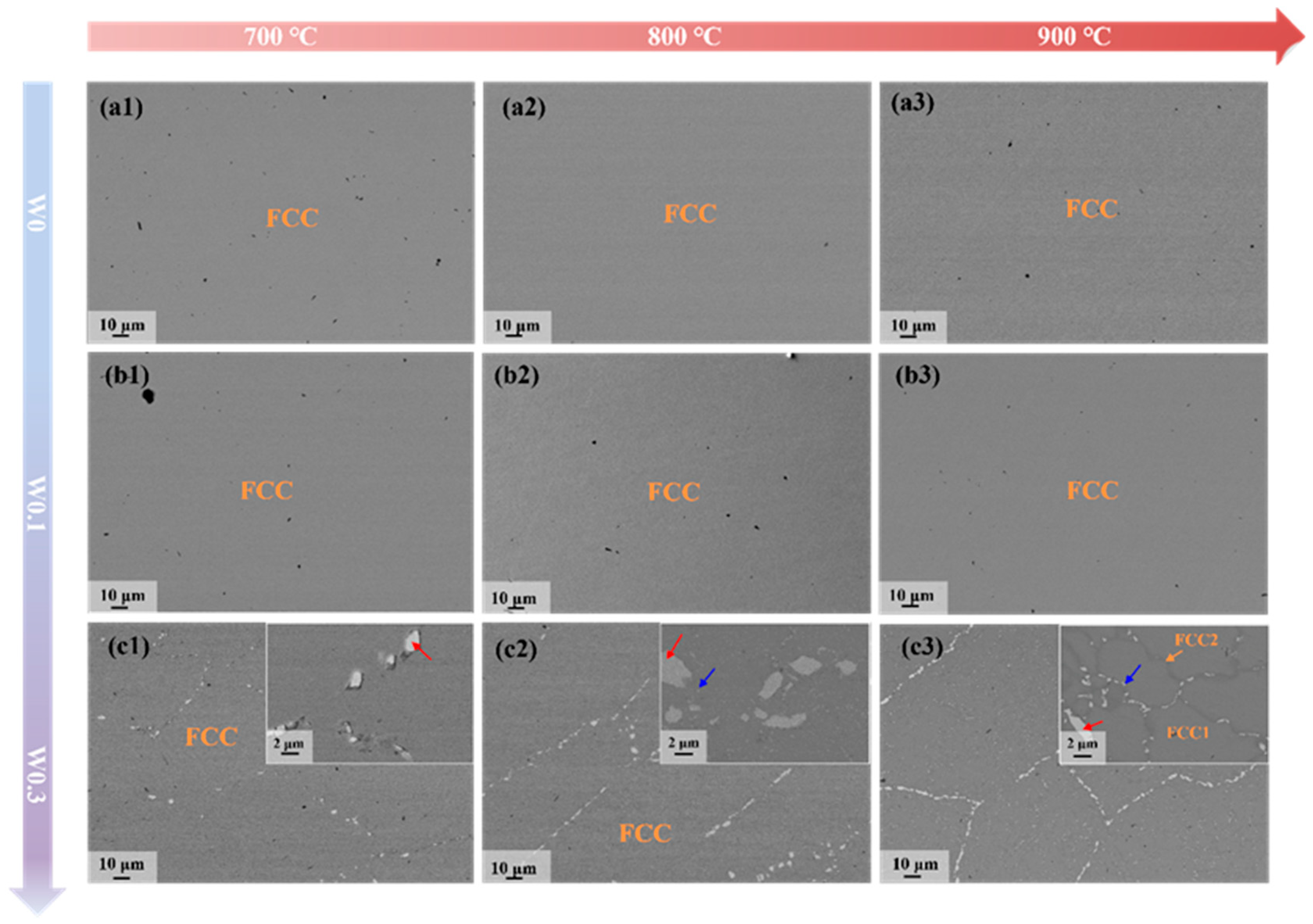
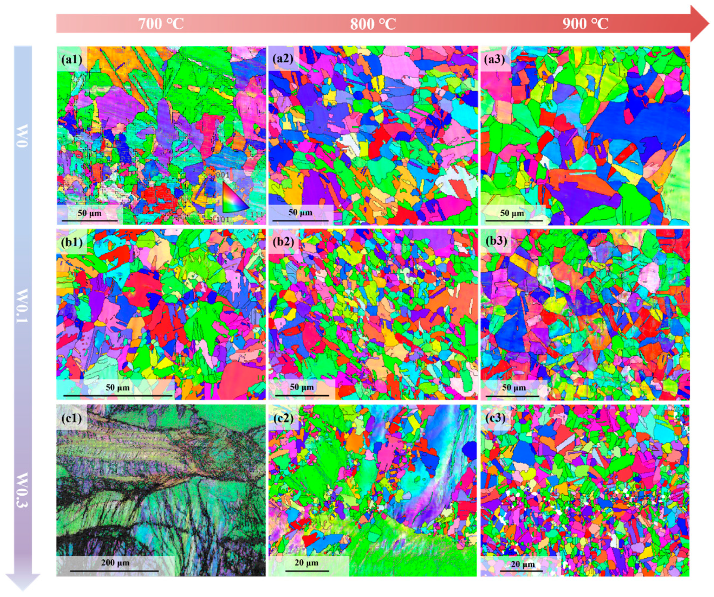
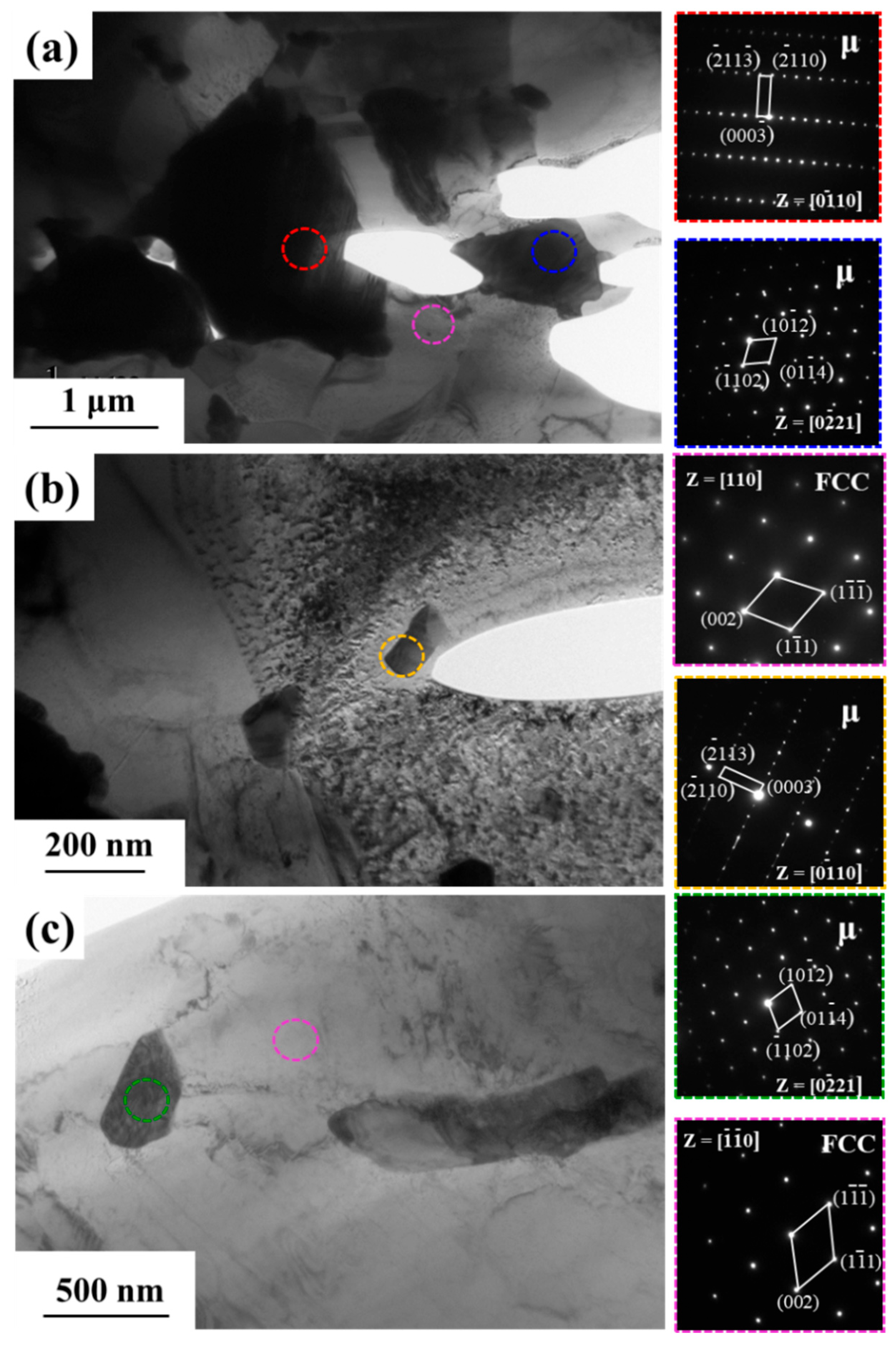
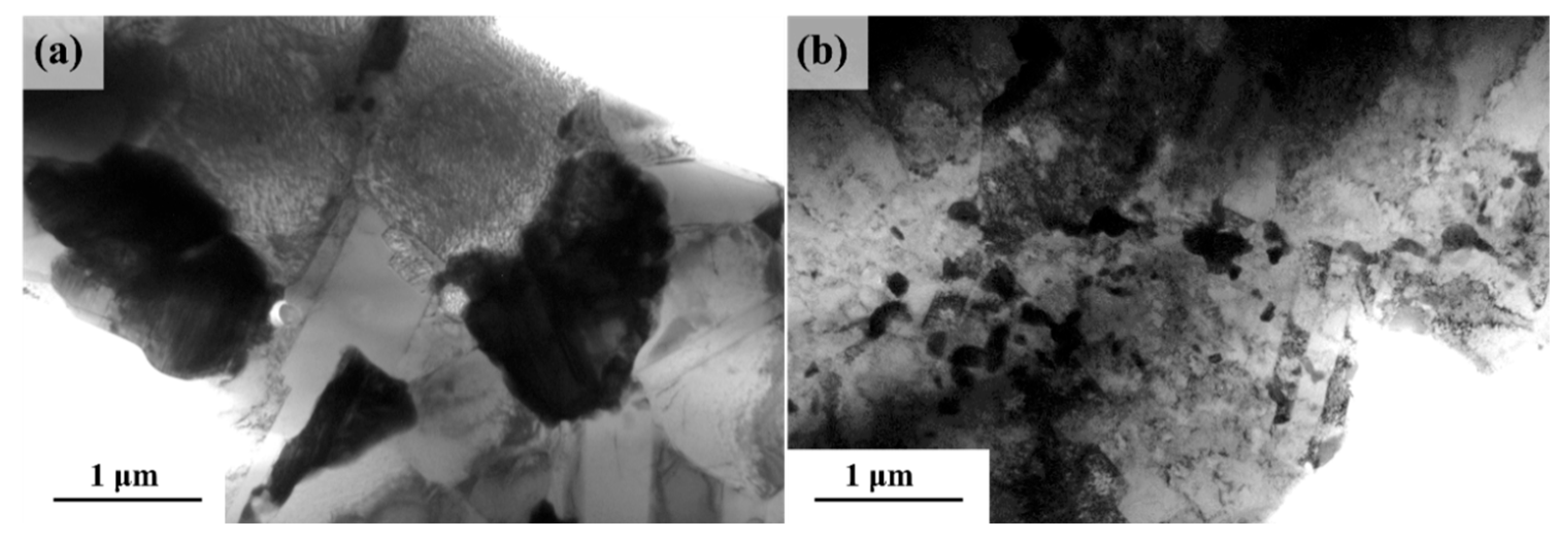
3.2. Microstructure Analysis

The microstructure under BSE mode of as-cast and annealed CoFeNiWx (x = 0, 0.1, and 0.3) MEAs is depicted in Figure S2 and Figure 2. From Figure S2, a single FCC solid solution phase formed with no distinct chemical segregations in all as-cast MEAs. After cold-rolling and annealing at 700 °C, 800 °C, and 900 °C, CoFeNi and CoFeNiW0.1 still retained a single FCC structure without forming precipitates in the FCC matrix. W with a larger atomic radius can completely dissolve in CoFeNiW0.1 MEA. Unlike as-cast CoFeNiW0.3 with a single FCC structure, coarse particles (denoted by red arrows) with an average diameter of ~2 μm appeared in cold-rolled CoFeNiW0.3 after annealing at 700 °C, 800 °C, and 900 °C. Fine particles (denoted by blue arrows) with the average diameters of ~144 nm and ~225 nm were found in CoFeNiW0.3 after annealing at 800 °C and 900 °C. The chemical compositions of different regions in cold-rolled CoFeNiWx (x = 0, 0.1, and 0.3) MEAs after annealing are shown in Table 1. For CoFeNiW0.3 MEA annealed at 900 °C, W-rich fine particles precipitated from the FCC matrix, resulting in darker contrasts near these fine particles. This phenomenon is possibly due to a larger amount of W consumed by the precipitated phase. However, no obvious fine particles can be observed in CoFeNiW0.3 annealed at 700 °C, which could be due to the sluggish diffusion process in this MEA. Coarse particles and fine particles were both W-rich phases. According to the XRD results, these particles should belong to the μ phase, but needed to be confirmed further by TEM. The BSE images of homogenized and cold-rolled CoFeNiW0.3 are shown in Figure S3. It can be inferred that W-rich coarse particles formed after homogenizing. Fine W-rich particles precipitated from the CoFeNi matrix after annealing at 800 °C and 900 °C.
The EBSD inverse pole figure (IPF) images of cold-rolled CoFeNiWx (x = 0, 0.1, and 0.3) MEAs after annealing at 700 °C, 800 °C, and 900 °C are given in Figure 3. For cold-rolled CoFeNi MEA annealed at 700 °C, 800 °C, and 900 °C, its average grain sizes were measured to be 16.9 μm, 17.1 μm, and 20 μm, respectively. The average grain sizes of CoFeNiW0.1 MEA after annealing were significantly smaller compared to CoFeNi, which were measured to be 8.2 μm, 12.3 μm, and 13.5 μm, respectively. This is because W as solute atoms can pin the migration of grain boundaries and effectively hinder the grain growth. The additions of W significantly affected the recrystallization process of CoFeNiW0.3 by solute-drag effect and Zener pinning effect. Specifically, upon annealing at 700 °C, CoFeNiW0.3 exhibited elongated grains with a distinct non-recrystallized microstructure. When CoFeNiW0.3 MEA was annealed at 800 °C, it displayed partial recrystallization, featuring the coexistence of non-recrystallized and recrystallized regions. The fractions of non-recrystallized and recrystallized regions were estimated to be 51.6% and 48.4%, respectively. With increasing annealing temperature being further elevated to 900 °C, fully recrystallized grains can be observed in CoFeNiW0.3.
TEM characterizations were further carried out to investigate the phase structure in CoFeNiW0.3 MEA. The bright-field images and corresponding selected area electron diffraction (SAED) patterns are shown in Figure 4. As can be seen in Figure 4a, the coarser particles belonged to the Fe7W6-type μ phase. From Figure 4b,c, fine precipitates formed during annealing were also confirmed to be μ-phase. In contrast to the reported crystal structures of CrFeNiW0.1 MEA, only μ phase appeared in CoFeNiWx MEAs due to the absence of the Cr element to avoid the formation of σ phase [14].

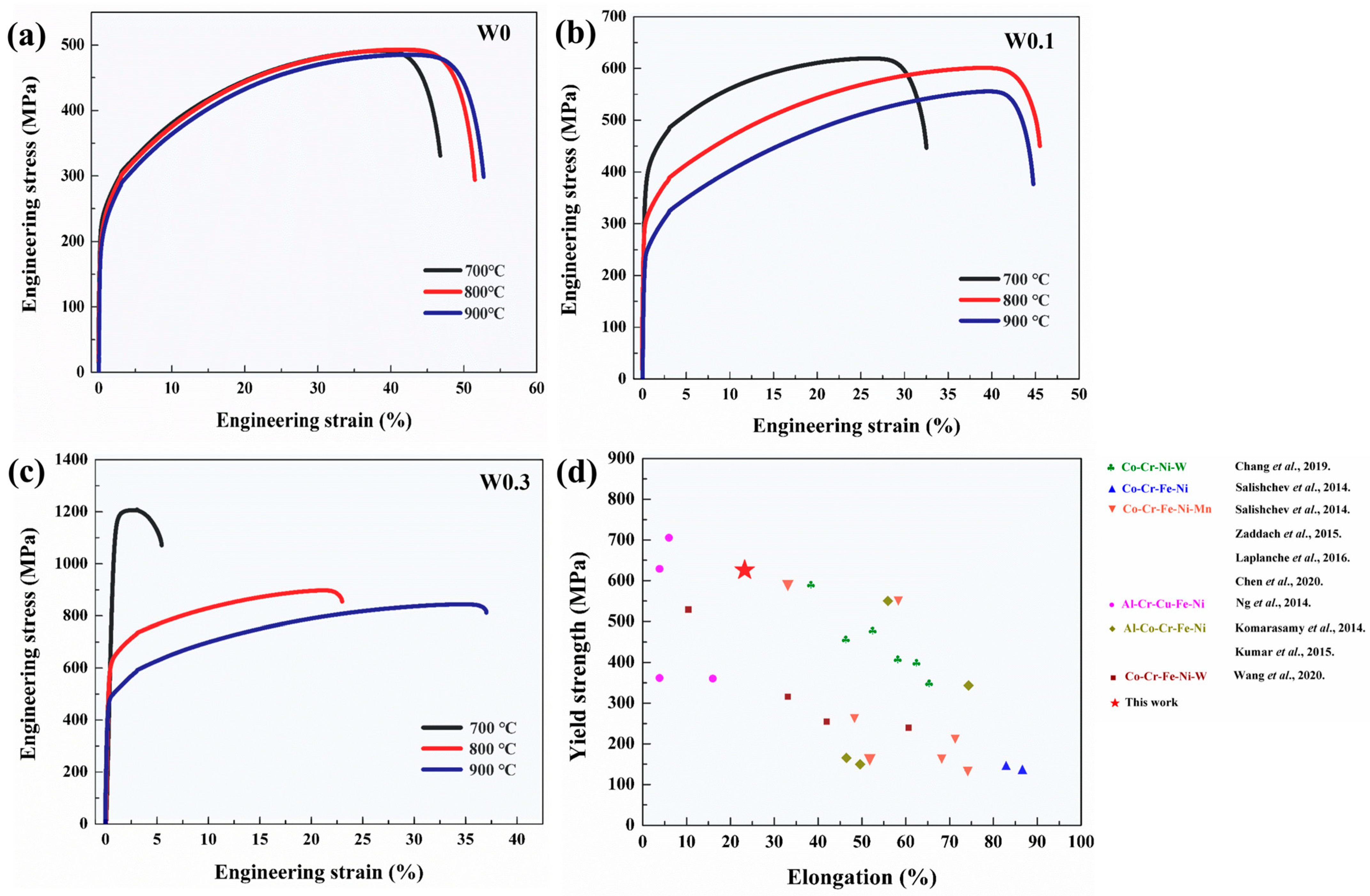
3.3. Mechanical Properties

The engineering stress-strain curves of cold-rolled CoFeNiWx (x = 0, 0.1, and 0.3) MEAs annealing at 700 °C, 800 °C, and 900 °C for 1 h were depicted in Figure 5a–c. In addition, their mechanical properties were summarized in Table 2. With increasing annealing temperatures, the yield strength (YS) values of CoFeNiWx (x = 0, 0.1, and 0.3) decreased, while the elongation (EL) of CoFeNiWx (x = 0 and 0.3) increased. In contrast to EL variations in CoFeNi and CoFeNiW0.3, the EL of CoFeNiW0.1 annealed at 800 °C was similar to CoFeNiW0.1 annealed at 900 °C. It was possibly because the finer grains in CoFeNiW0.1 annealed at 800 °C enabled more stress concentrations distributed among more grains to avoid its failure upon tensile stress [15]. From Table 2, it is obvious that CoFeNiW0.3 annealed at 800 °C can exhibit better comprehensive mechanical properties among CoFeNiWx MEAs. In Figure 5d, compared to other reported HEAs and MEAs, CoFeNiW0.3 annealed at 800 °C can display superior YS and EL.

4. Discussions

4.1. Phase Formations

In this study, a minor amount of W can completely dissolve in CoFeNi MEA to form an FCC-structured solid solution, while the μ phase is formed in CoFeNi by adding more W element. From previous studies, there are several solid solutions formation criteria for HEAs or MEAs, such as H m i x , δ , Λ , γ , and Ω [24,25,26,27]. The calculated results are shown in Table 3.
H m i x = i = 1 , i j n 4 H m i x A B c i c j
δ = i = 1 n c i ( 1 r i / r ¯ ) 2
r ¯ = i = 1 n c i r i
S m i x = R i = 1 n ( c i l n c i )
T m = i = 1 n c i ( T m ) i
Λ = S m i x δ 2
γ = ( 1 r s + r ¯ 2 r ¯ 2 r s + r ¯ 2 ) / ( 1 r L + r ¯ 2 r ¯ 2 r L + r ¯ 2 )
Ω = T m S m i x H m i x
where H m i x and δ are mixing enthalpy and atomic size differences, respectively; c i and c j are the atomic percent of the ith element and jth element, respectively; r ¯ is the average atomic radius, r i as the atomic radius of the ith element can be obtained from Refs. [28,29]; S m i x is the mixing entropy, R is gas constant (8.314 J/mol/K); T m is the average melting point, ( T m ) i is melting point of ith element, as cited from literature [28,29,30]; Λ is a geometrical parameter; γ is the atomic packing parameter, r s and r L are the radii of the smallest and largest atoms, respectively; Ω is a parameter of comparing the relative magnitudes between the entropy effect and the enthalpy effect.
For forming solid solutions, the calculated parameters ( H m i x , δ , Λ , γ , and Ω ) should meet the following requirements [24,25,26,27]: (1) −15 < ΔHmix < 5 kJ/mol, δ ≤ 6.6%; (2) Λ > 0 .96; (3) γ < 1 .175; (4) Ω 1 .1, δ ≤ 6.6%. In CoFeNiWx (x = 0, 0.1, and 0.3) MEAs, the values of H m i x , δ , Λ , γ and Ω all satisfied criteria abovementioned to form solid solution phases. However, based on experimental investigations, a single FCC solid solution phase formed in as-cast CoFeNiWx alloys, whereas μ appeared in CoFeNiW0.3 after homogenizing and annealing. Incorporating alloying elements with a larger atomic radius than other elements in the alloy system into an FCC lattice would induce lattice distortion [11]. The resulting lattice distortion energy destabilized the FCC matrix, promoting the appearance of a second phase. Nevertheless, there was not enough time for as-cast CoFeNiW0.3 to nucleate and precipitate due to the higher cooling rate during the solidification process, which enabled the as-cast CoFeNiW0.3 MEA to attain a saturated state. After homogenizing and annealing, the solubility of W with the highest melting point reduced with decreasing temperatures, and thus, W-rich μ phase tended to form in the alloy due to the clustering of W atoms.

4.2. Strengthening Mechanisms

CoFeNiW0.3 annealed at 800 °C can exhibit better comprehensive mechanical properties. Herein, the yield strength increment of CoFeNiW0.3 MEA annealed at 800 °C was discussed in detail to clarify its primary strengthening mechanism. The strengthening mechanisms for the MEA can be attributed to solid solution strengthening, grain refinement strengthening, dislocation strengthening, as well as precipitation strengthening.
σ = σ 0 + σ S S + f R S · σ G B + σ D + σ P
where σ 0 is the friction stress, approximately equivalent to the yield strength of as-cast CoFeNi (~112 MPa, as shown in Figure S4); f R S is the fraction of recrystallized regions (48.4%).
The contribution from solid solution strengthening can be calculated from the following equation [14]:
σ S S = M · G · ε s 3 / 2 · c 1 / 2 700
where M is the Taylor factor (3.06) [14]; G (78 GPa) is the shear modulus of CoFeNi, which can be obtained by the rule of mixture [16], and C is the atomic concentration of W dissolving in the FCC matrix. As given in Table 1, the W concentration in the FCC matrix was slightly larger than its nominal chemical composition, possibly due to the limited accuracy of the EDS technique. Therefore, the content of W dissolved in FCC of CoFeNiW0.3 was estimated to be ~0.0625 because CoFeNiW0.2 can show a single FCC phase (as depicted in Figure S5) after thermal-mechanical processing. The interaction parameter ε s is expressed as [14]:
ε s = ε G 1 + 0.5 ε G 3 · ε a
where ε G is elastic mismatch,   ε a is atomic size mismatch. They are expressed as [14]:
ε G = 1 G G c
ε a = 1 a a c
where a is the lattice constant of as-cast CoFeNi (0.35783 nm). ε G is usually neglected. Therefore, the strength contribution from solid solution strengthening was ~28.2 MPa.
The σ G B can be calculated by Equation (14) [31]:
σ G B = k d 1 / 2
where k is the Hall–Petch coefficient (~363 MPa·μm1/2) [32]; d is the average grain size of W0.3-800 °C (~3.5 μm). The value of σ G B was estimated to be ~194 MPa.
The contribution value from dislocation strengthening was normally estimated using the following formula [14]:
σ D = M α G b ρ 1 / 2
where α as a constant is 0.2 [14]; b is Burger’s vector (~0.256 nm); ρ as the dislocation density (4.36 × 10¹⁴ m2) was calculated by Equation (16) [33]:
ρ = 2 θ μ b
where θ is the local misorientation angle obtained from EBSD (0.0173); μ is the step size (310 nm). Combining Equations (15) and (16), the calculated σ D was about ~255.2 MPa.
The strengthening effect of μ phase can be explained by the Orowan bypass mechanism, which was calculated using Equations (17) and (18) [14]:
σ P i = 0.4 M G b π 1 ϑ · ln ( 2 r i ¯ / b ) L P i
σ P = σ P 1 2 + σ P 2 2
where ϑ is Poisson’s ratio (0.24) [14]; r i ¯ = 2 / 3 r i , r i is the mean particle radius of μ phases (1.270 μm for coarse μ phase and 0.072 μm for fine μ phase); The mean interparticle distances ( L P ) for coarse and fine μ phase were measured to be 3.412 μm and 0.401 μm, respectively. As a result, the contribution to yield strength from μ phase was ~138.4 MPa.
From the analysis mentioned above, the calculated sum of the yield strength was approximately 627.7 MPa, which was close to the experimental value with a negligible discrepancy.

4.3. Deformation Mechanisms

To elucidate the deformation mechanism of cold-rolled CoFeNiW0.3 annealed at 800 °C, the microstructures of this MEA before and after deformation are depicted in Figure 6. From Figure 6a, CoFeNiW0.3 annealed at 800 °C exhibited a distinct partially recrystallized microstructure. Many dislocations were distributed in non-recrystallized regions, while recrystallized regions were relatively clear without obvious dislocations. After deformation, dislocation motions were effectively hindered by μ phase, which significantly piled up around μ phase particles (as given in Figure 6b). No obvious stacking faults or deformation twins were found in deformed CoFeNiW0.3. Therefore, it can be concluded that the deformation mechanism of cold-rolled CoFeNiW0.3 annealed at 800 °C was mainly attributed to dislocation motions.

5. Conclusions

In this work, the effect of W contents and annealing temperatures was studied. After thermal-mechanical processing, CoFeNi and CoFeNiW0.1 still maintained a single FCC structure. However, coarse μ particles with an average diameter of ~2 μm appeared in CoFeNiW0.3 MEA after homogenizing. After annealing at 800 °C and 900 °C, fine particles emerged in CoFeNiW0.3, with the average diameters of ~144 nm and ~225 nm, respectively. W additions can significantly hinder the recrystallization process of CoFeNiWx MEAs. When CoFeNiW0.3 MEA was subjected to 800 °C, the alloy showed a partially recrystallized microstructure with the coexistence of non-recrystallized and recrystallized regions. This alloy can exhibit better comprehensive mechanical properties. During the deformation process, dislocation motions were the controlled deformation mechanism. Our work can provide a better understanding of the microstructure evolution and mechanical properties of W-added MEAs, and give a reference for designing both MEAs and HEAs.

Supplementary Materials

The following supporting information can be downloaded at: https://www.mdpi.com/article/10.3390/met15080854/s1, Figure S1: The XRD patterns of as-cast CoFeNiWx (x = 0, 0.1 and 0.3) medium entropy alloys (MEAs); Figure S2: The microstructure of as-cast CoFeNiWx (x = 0, 0.1 and 0.3) MEAs; Figure S3: The microstructure of (a) homogenized CoFeNiW0.3, (b) cold-rolled CoFeNiW0.3; Figure S4: The engineering stress-strain curve of as-cast CoFeNi; Figure S5: The microstructure of cold-rolled CoFeNiW0.2 after annealing at 800 ℃.

Author Contributions

Conceptualization, Y.C., H.M., L.Y., Y.S. and R.G.; methodology, Y.C., H.M., L.Y., Y.S. and R.G.; validation, Y.C., L.Y. and R.G.; formal analysis, Y.C. and H.M.; investigation, Y.C., L.Y. and Y.S.; resources, Y.S. and R.G.; data curation, Y.C.; writing—original draft preparation, Y.C. and H.M.; writing—review and editing, Y.C., H.M., L.Y., Y.S. and R.G.; visualization, Y.C., L.Y. and Y.S.; supervision, H.M. and R.G.; funding acquisition, H.M. and R.G. All authors have read and agreed to the published version of the manuscript.

Funding

This work was financially supported by the National Natural Science Foundation of China [grant No. 52404378], the Basic Scientific Research Project of Liaoning Provincial Education Department [grant No. JYTQN2023009] and Dalian Science & Technology Innovation Foundation Project [grant No. 2024JJ11PT003].

Data Availability Statement

The original contributions presented in this study are included in the article/Supplementary Material. Further inquiries can be directed to the corresponding author.

Conflicts of Interest

The authors declare no conflicts of interest.

References

  1. Ye, Y.F.; Wang, Q.; Lu, J.; Liu, C.T.; Yang, Y. High-entropy alloy: Challenges and prospects. Mater. Today 2016, 19, 349–362. [Google Scholar] [CrossRef]
  2. Yeh, J.W. Recent progress in high-entropy alloys. Ann. Chim. Sci. Mat. 2006, 31, 633–648. [Google Scholar] [CrossRef]
  3. Li, Z.Z.; Zhao, S.T.; Ritchie, R.O.; Meyers, M.A. Mechanical properties of high-entropy alloys with emphasis on face-centered cubic alloys. Prog. Mater. Sci. 2019, 102, 296–345. [Google Scholar] [CrossRef]
  4. Liu, W.H.; Yang, T.; Liu, C.T. Precipitation hardening in CoCrFeNi-based high entropy alloys. Mater. Chem. Phys. 2018, 210, 2–11. [Google Scholar] [CrossRef]
  5. Wu, Z.; Bei, H.; Pharr, G.M.; George, E.P. Temperature dependence of the mechanical properties of equiatomic solid solution alloys with face-centered cubic crystal structures. Acta Mater. 2014, 81, 428–441. [Google Scholar] [CrossRef]
  6. Wang, L.; Wu, X.Y.; Su, H.J.; Deng, B.; Liu, G.; Han, Z.H.; Su, Y.N.; Huang, Y.D.; Zhang, Y.P.; Shen, J.; et al. Microstructure and mechanical property of novel L12 nanoparticles-strengthened CoFeNi-based medium entropy alloys. Mater. Sci. Eng. A 2022, 840, 142917. [Google Scholar] [CrossRef]
  7. Chen, Y.; Deng, H.W.; Xie, Z.M.; Wang, M.M.; Yang, J.F.; Zhang, T.; Xiong, Y.; Liu, R.; Wang, X.P.; Fang, Q.F.; et al. Tailoring microstructures and tensile properties of a precipitation-strengthened (FeCoNi)94Ti6 medium-entropy alloy. J. Alloys Compd. 2020, 828, 154457. [Google Scholar] [CrossRef]
  8. Ye, Z.H.; Li, C.W.; Zhang, X.Y.; Liao, Y.; Gu, J.F. The influence of vanadium element on the microstructure and mechanical properties of (FeCoNi)100-xVx high-entropy alloys. Mater. Charact. 2022, 192, 112232. [Google Scholar] [CrossRef]
  9. Yang, T.; Zhao, Y.L.; Tong, Y.; Jiao, Z.B.; Wei, J.; Cai, J.X.; Han, X.D.; Chen, D.; Hu, A.; Kai, J.J.; et al. Multicomponent intermetallic nanoparticles and superb mechanical behaviors of complex alloys. Science 2018, 362, 933–937. [Google Scholar] [CrossRef]
  10. He, J.Y.; Wang, H.; Huang, H.L.; Xu, X.D.; Chen, M.W.; Wu, Y.; Liu, X.J.; Nieh, T.G.; An, K.; Lu, Z.P. A precipitation-hardened high-entropy alloy with outstanding tensile properties. Acta Mater. 2016, 102, 187–196. [Google Scholar] [CrossRef]
  11. Liu, W.H.; He, J.Y.; Huang, H.L.; Wang, H.; Lu, Z.P.; Liu, C.T. Effects of Nb additions on the microstructure and mechanical property of CoCrFeNi high-entropy alloys. Intermetallics 2015, 60, 1–8. [Google Scholar] [CrossRef]
  12. Chang, R.B.; Fang, W.; Bai, X.; Xia, C.Q.; Zhang, X.; Yu, H.Y.; Liu, B.X.; Yin, F.X. Effects of tungsten additions on the microstructure and mechanical properties of CoCrNi medium entropy alloys. J. Alloys Compd. 2019, 790, 732–743. [Google Scholar] [CrossRef]
  13. Cheng, G.S.; Shi, Y.Z.; Wang, Y.H.; Zhang, F.; Li, R.; Zhou, Y.H.; Wu, Z.G.; Ma, C.; Lei, Z.F.; Lu, Z.P. Enhancing strengthening effect of topologically close-packed superlattices in medium-entropy alloys via enabling imperfect atomic packing. Acta Mater. 2024, 271, 119903. [Google Scholar] [CrossRef]
  14. Cui, Y.Q.; Ma, H.; Yang, L.; Shao, Y.; Pang, H.F.; Zhu, H.H.; Zhang, J.; Sun, W.T.; Guan, R.G. A multiscale-phase-structured CrFeNiW0.1 medium entropy alloy with outstanding strength-ductility synergy. Mater. Sci. Eng. A 2025, 933, 148300. [Google Scholar] [CrossRef]
  15. Wu, Z.G.; Guo, W.; Jin, K.; Poplawsky, J.D.; Gao, Y.F.; Bei, H.B. Enhanced strength and ductility of a tungsten-doped CoCrNi medium-entropy alloy. J. Mater. Res. 2018, 33, 3301–3309. [Google Scholar] [CrossRef]
  16. Salishchev, G.A.; Tikhonovsky, M.A.; Shaysultanov, D.G.; Stepanov, N.D.; Kuznetsov, A.V.; Kolodiy, I.V.; Tortika, A.S.; Senkov, O.N. Effect of Mn and V on structure and mechanical properties of high-entropy alloys based on CoCrFeNi system. J. Alloys Compd. 2014, 591, 11–21. [Google Scholar] [CrossRef]
  17. Zaddach, A.J.; Scattergood, R.O.; Koch, C.C. Tensile properties of low-stacking fault energy high-entropy alloys. Mater. Sci. Eng. A 2015, 636, 373–378. [Google Scholar] [CrossRef]
  18. Laplanche, G.; Kostka, A.; Horst, O.M.; Eggeler, G.; George, E.P. Microstructure evolution and critical stress for twinning in the CrMnFeCoNi high-entropy alloy. Acta Mater. 2016, 118, 152–163. [Google Scholar] [CrossRef]
  19. Chen, S.J.; Oh, H.S.; Gludovatz, B.; Kim, S.J.; Park, E.S.; Zhang, Z.; Ritchie, R.O.; Yu, Q. Real-time observations of TRIP-induced ultrahigh strain hardening in a dual-phase CrMnFeCoNi high-entropy alloy. Nat. Commun. 2020, 11, 826. [Google Scholar] [CrossRef]
  20. Ng, C.; Guo, S.; Luan, J.H.; Wang, Q.; Lu, J.; Shi, S.Q.; Liu, C.T. Phase stability and tensile properties of Co-free Al0.5CrCuFeNi2 high-entropy alloys. J. Alloys Compd. 2014, 584, 530–537. [Google Scholar] [CrossRef]
  21. Komarasamy, M.; Kumar, N.; Tang, Z.; Mishra, R.S.; Liaw, P.K. Effect of Microstructure on the Deformation Mechanism of Friction Stir-Processed Al0.1CoCrFeNi High Entropy Alloy. Mater. Res. Lett. 2014, 3, 30–34. [Google Scholar] [CrossRef]
  22. Kumar, N.; Komarasamy, M.; Nelaturu, P.; Tang, Z.; Liaw, P.K.; Mishra, R.S. Friction Stir Processing of a High Entropy Alloy Al0.1CoCrFeNi. JOM 2015, 67, 1007–1013. [Google Scholar] [CrossRef]
  23. Wang, L.; Wang, L.; Tang, Y.C.; Luo, L.; Luo, L.S.; Su, Y.Q.; Guo, J.J.; Fu, H.Z. Microstructure and mechanical properties of CoCrFeNiWx high entropy alloys reinforced by μ phase particles. J. Alloys Compd. 2020, 843, 155997. [Google Scholar] [CrossRef]
  24. Zhang, Y.; Zhou, Y.J.; Lin, J.P.; Chen, G.L.; Liaw, P.K. Solid-Solution Phase Formation Rules for Multi-component Alloys. Adv. Eng. Mater. 2008, 10, 534–538. [Google Scholar] [CrossRef]
  25. Singh, A.K.; Kumar, N.; Dwivedi, A.; Subramaniam, A. A geometrical parameter for the formation of disordered solid solutions in multi-component alloys. Intermetallics 2014, 53, 112–119. [Google Scholar] [CrossRef]
  26. Wang, Z.J.; Huang, Y.H.; Yang, Y.; Wang, J.C.; Liu, C.T. Atomic-size effect and solid solubility of multicomponent alloys. Scr. Mater. 2015, 94, 28–31. [Google Scholar] [CrossRef]
  27. Yang, X.; Zhang, Y. Prediction of high-entropy stabilized solid-solution in multi-component alloys. Mater. Chem. Phys. 2012, 132, 233–238. [Google Scholar] [CrossRef]
  28. Zhang, L.J.; Yu, P.F.; Zhang, M.D.; Liu, D.J.; Zhou, Z.; Ma, M.Z.; Liaw, P.K.; Li, G.; Liu, R.P. Microstructure and mechanical behaviors of GdxCoCrCuFeNi high-entropy alloys. Mater. Sci. Eng. A 2017, 707, 708–716. [Google Scholar] [CrossRef]
  29. Dong, Y.; Lu, Y.P. Effects of Tungsten Addition on the Microstructure and Mechanical Properties of Near-Eutectic AlCoCrFeNi2 High-Entropy Alloy. J. Mater. Eng. Perform. 2017, 27, 109–115. [Google Scholar] [CrossRef]
  30. Yuan, Y.; Han, Y.; Xu, K.; Tang, S.S.; Zhang, Y.H.; Lv, Y.Z.; Yang, Y.H.; Jiang, X.; Chang, K.K. Revealing the solidification microstructure evolution and strengthening mechanisms of additive-manufactured W-FeCrCoNi alloy: Experiment and simulation. J. Mater. Sci. Technol. 2025, 204, 302–313. [Google Scholar] [CrossRef]
  31. Li, H.C.; Wang, J.; Zhang, W.Y.; Zhao, J.W.; Li, J.S.; Fu, M.W. Achieving superior ductility with ultrahigh strength via deformation and strain hardening in the non-recrystallized regions of the heterogeneous-structured high-entropy alloy. Acta Mater. 2025, 283, 120572. [Google Scholar] [CrossRef]
  32. Deng, H.W.; Jiang, Y.; Liao, B.K.; Zhao, Z.; Wang, L.; Zhang, T. Mechanical properties and corrosion behavior of precipitation-strengthened FeCoNi-Tix (x = 0, 3, 6 at. %) multi-principal element alloys. J. Mater. Res. Technol. 2023, 27, 2922–2928. [Google Scholar] [CrossRef]
  33. Sun, W.T.; Fu, Y.; Ma, H.; Wang, Y.; Gao, M.Q.; Kong, X.Q.; Guan, R.G. High-strength AlCoCrFeNi2.1 eutectic high entropy alloy skeleton with hollow brick wall structures by selective laser melting. Mater. Sci. Eng. A 2023, 887, 145757. [Google Scholar]
Figure 1. (ac) XRD patterns of cold-rolled CoFeNiWx (x = 0, 0.1, and 0.3) MEAs after annealing at 700 °C, 800 °C, and 900 °C for 1 h. (d) Lattice constants of the FCC phase of CoFeNiWx MEAs.
Metals 15 00854 g001
Figure 2. The BSE images of cold-rolled CoFeNiWx (x = 0, 0.1, and 0.3) MEAs after annealing at 700 °C, 800 °C, and 900 °C: (a1a3) CoFeNi, (b1b3) CoFeNiW0.1, (c1c3) CoFeNiW0.3.
Metals 15 00854 g002
Figure 3. The EBSD IPF images of cold-rolled CoFeNiWx (x = 0, 0.1, and 0.3) MEAs after annealing at 700 °C, 800 °C, and 900 °C: (a1a3) CoFeNi, (b1b3) CoFeNiW0.1, (c1c3) CoFeNiW0.3.
Metals 15 00854 g003
Figure 4. (a,b) TEM BF images and corresponding SAED patterns of cold-rolled CoFeNiW0.3 after annealing at 800 °C, (c) TEM BF images of cold-rolled CoFeNiW0.3 after annealing at 900 °C.
Metals 15 00854 g004
Figure 5. (ac) Engineering stress-strain curves of cold-rolled CoFeNiWx (x = 0, 0.1, and 0.3) after annealing at 700 °C, 800 °C, and 900 °C for 1 h, (d) mechanical properties comparisons of CoFeNiWx with reported HEAs and MEAs, adapted from Refs. [12,16,17,18,19,20,21,22,23].
Metals 15 00854 g005
Figure 6. The BF images of cold-rolled CoFeNiW0.3 annealed at 800 °C: (a) before deformation, (b) after deformation.
Metals 15 00854 g006
Table 1. Chemical compositions (in at.%) of CoFeNiWx (x = 0, 0.1, and 0.3) MEAs by SEM-EDS.
Alloys RegionsCoFeNiW
W0-700 °CFCC33.7733.5632.670
W0-800 °CFCC33.7533.6032.640
W0-900 °CFCC33.3733.6033.030
W0.1-700 °CFCC32.5332.5231.443.50
W0.1-800 °CFCC32.5032.4531.213.83
W0.1-900 °CFCC32.4132.6331.093.87
W0.3-700 °CFCC29.9830.2830.199.55
Coarse particle25.6019.2211.7543.43
W0.3-800 °CFCC30.5930.1429.559.73
Coarse particle25.7918.7911.2244.19
Fine particle29.9026.1120.3423.64
W0.3-900 °CFCC128.4030.7825.9314.89
FCC229.8730.4127.0112.71
Coarse particle22.6019.6511.2646.49
Fine particle24.8622.5113.6239.01
Table 2. The mechanical properties of CoFeNiWx (x = 0, 0.1, and 0.3) MEAs.
MEAsYS (MPa)UTS (MPa)EL (%)
W0-700 °C23249147.1
W0-800 °C20549351.7
W0-900 °C19248552.9
W0.1-700 °C37361932.5
W0.1-800 °C30660145.5
W0.1-900 °C24255444.8
W0.3-700 °C106312075.5
W0.3-800 °C62089823
W0.3-900 °C48484537
Table 3. The calculated parameters of phase formations in CoFeNiWx (x = 0, 0.1, and 0.3) MEAs.
MEAs H mix
(kJ/mol)
δ
(%)
S mix
(J/mol/K)
Λ
(J/mol/K)
γ Ω
CoFeNi−1.3330.6539.13421.4071.01712.118
CoFeNiW0.1−1.4152.07310.0242.3321.13412.970
CoFeNiW0.3−1.5433.24610.8361.0281.13313.654
Disclaimer/Publisher’s Note: The statements, opinions and data contained in all publications are solely those of the individual author(s) and contributor(s) and not of MDPI and/or the editor(s). MDPI and/or the editor(s) disclaim responsibility for any injury to people or property resulting from any ideas, methods, instructions or products referred to in the content.

