Article

Effect of Heat Treatments and Related Microstructural Modifications on High-Cycle Fatigue Behavior of Powder Bed Fusion–Laser Beam-Fabricated Ti-6Al-2Sn-4Zr-6Mo Alloy

by
Gianluca Pirro
1,*,
Alessandro Morri
1,
Alessandra Martucci
2,
Mariangela Lombardi
2 and
Lorella Ceschini
1
1
Department of Industrial Engineering (DIN), Alma Mater Studiorum—University of Bologna, Viale del Risorgimento 4, 40136 Bologna, Italy
2
Department of Applied Science and Technology, Politecnico di Torino, Corso Duca degli Abruzzi 24, 10129 Torino, Italy
*
Author to whom correspondence should be addressed.
Metals 2025, 15(8), 849; https://doi.org/10.3390/met15080849 (registering DOI)
Submission received: 1 July 2025 / Revised: 22 July 2025 / Accepted: 26 July 2025 / Published: 29 July 2025

Abstract

The study investigates the influence of microstructures on fatigue behavior and failure mechanisms of the α-β titanium alloy Ti6246, fabricated via Powder Bed Fusion-Laser Beam (PBF-LB). In particular, the investigation assesses the effect of two post-processing heat treatments, namely α-β annealing at 875 °C (AN875) and solution treatment at 825 °C followed by aging at 500 °C (STA825), on the alloy’s rotating and bending fatigue behavior. The results indicate that the STA825 condition provides superior fatigue resistance (+25%) compared to AN875, due to the presence of a finer bilamellar microstructure, characterized by thinner primary α lamellae (αp) and a more homogeneous distribution of secondary α lamellae (αs) within the β matrix. Additionally, an investigation conducted using the Kitagawa–Takahashi (KT) approach and the El-Haddad model, based on the relationship between the fatigue limit and defect sensitivity, revealed improved crack propagation resistance from pre-existing defects (ΔKth) for the STA825 condition compared to AN875. Notably, the presence of fine αs after aging for STA825 is effective in delaying crack nucleation and propagation at early stages, while refined αp contributes to hindering macrocrack growth. The fatigue behavior of the STA825-treated Ti6246 alloy was even superior to that of the PBF-LB-processed Ti64, representing a viable alternative for the production of high-performance components in the automotive and aerospace sectors.

Graphical Abstract

1. Introduction

The properties of titanium alloys, including their high strength-to-weight ratio, optimal fracture toughness, and excellent high-temperature and oxidation resistance, have led to their widespread adoption in sectors such as aerospace, motorsport, and automotive [1,2,3,4]. The growing demand for high-performance components, combined with the need for complex geometries unachievable through conventional machining technologies [5], has driven the adoption of additive manufacturing (AM) [6,7]. Among AM technologies, Powder Bed Fusion–Laser Beam (PBF-LB) is the most extensively studied and widely used, as it enables the fabrication of strong, lightweight, and geometrically complex titanium components, including those with internal channels, directly from Computer-Aided models.
Currently, the α-β titanium alloy Ti-6Al-4V (Ti64) is the most widely used in AM due to the following: (i) its long-standing application in the aerospace and automotive industries; (ii) its well-documented excellent mechanical performance; (iii) its availability on the market. For these reasons, PBF-LB Ti64 has been the subject of extensive research [3,8], particularly aimed at maximizing fatigue strength, as fatigue represents the primary cause of failure in automotive and aerospace components (e.g., airframe components, connecting rods, etc.).
However, the growing demand for enhanced performance in AM-produced components has sparked significant interest in alternative α-β titanium alloys, such as Ti-6Al-2Sn-4Zr-6Mo (Ti6246), which exhibits a higher β-phase fraction and enhanced mechanical potential compared to Ti64.
For conventionally processed Ti6246, the optimization of tailored heat treatments enables the achievement of high tensile properties [9,10]. In particular, these properties are attained through solution treatment below the β transus temperature, followed by aging, which promotes the formation of a fine bimodal microstructure consisting of a globular primary α phase (αp) in a fine α-β lamellar matrix [11]. Beyond static properties, Peters et al. [12] reported that Ti6246 exhibits superior fatigue strength compared to Ti64 in both high-cycle fatigue (HCF) and very-high-cycle fatigue (VHCF) regimes. This improvement is primarily attributed to the higher α phase fraction present in Ti64 compared to Ti6246 under similar heat treatment conditions, resulting from its higher content of α-stabilizing elements. In wrought titanium alloys, which are typically free of macroscopic defects, fatigue crack nucleation preferentially occurs within the αp, with subsequent propagation occurring either transgranularly within the α phase (especially when coarse) or along the α/β interfaces [13,14].
To date, no specific studies have been carried out on AM processed Ti6246. Nevertheless, it is well established that the unique microstructural features induced by PBF-LB in α-β Ti alloys significantly affect both tensile and fatigue behavior [15,16]. Many researchers have observed that high cooling rates typical of these processes can lead to the formation of metastable phases, such as α′ [17] and α″ martensite [6], depending on the β-stabilizer content. These metastable microstructures can negatively affect their reliability during service [18,19]. Although optimized heat treatment can increase the tensile properties of the alloys, making them comparable and even superior to those of conventionally processed alloys, similar improvements in fatigue resistance remain challenging. In fact, the high surface roughness, gas porosity, and lack of fusion (LoF) defects of PBF-LB parts generate localized stress concentrations that promote crack nucleation, significantly reducing fatigue resistance [20,21,22].
Leuders et al. [18] observed that for a Ti64 alloy produced by PBF-LB, α+β annealing treatment improved crack propagation resistance compared to the as-built state, due to the transformation of α′ martensite into a lamellar α+β structure. However, the heat treatment had no significant effect on crack nucleation resistance, which primarily occurred near pores. Yu et al. [15] extensively studied the effect of Solution Treating and Aging (STA) heat treatment within the α+β phase field on a Ti64 alloy fabricated via PBF-LB. Their findings revealed that this treatment promotes the formation of a distinct bilamellar microstructure, consisting of αp lamellae within a fine matrix of secondary α (αs) lamellae and a β phase, which exhibited enhanced fatigue resistance compared to the lamellar structure resulting from α+β annealing. This highlights the critical role of heat treatment optimization in improving fatigue performance.
Although the influence of microstructures on the fatigue behavior of α-β Ti64 alloys has been widely investigated, to the best of the authors’ knowledge, a research gap exists regarding the effect of heat treatment on the fatigue strength of PBF-LB Ti6246 alloys that requires further investigations. In previous works [23,24], the authors optimized the heat treatment parameters for PBF-LB Ti6246 and established correlations between its microstructural features and tensile properties. Building on these findings, the present study aims to investigate the effects of two heat treatments, STA and α+β annealing, on the fatigue behavior of PBF-LB Ti6246. Moreover, the correlation between fatigue failure and defects in the PBF-LB Ti6246 was investigated using the Kitagawa–Takahashi (KT) approach and the El-Haddad model [25,26], aiming to assess the potential for enhancing defect tolerance in this alloy. Indeed, enhancing defect tolerance could enable the elimination of the costly and time-consuming Hot Isostatic Pressing (HIP) process, which is commonly applied to titanium PBF-LB components to reduce internal defects and improve fatigue performance.

2. Materials and Methods

2.1. Sample Production

The PBF-LB samples were produced by gas-atomized Ti6246 powders supplied by Eckart TLS (Hartenstein, Zwickau, Germany). Glow Discharge Optical Emission Spectroscopy (GD-OES, GDA-650, Spectruma Analytik GmbH, Hof, Germany) was employed to verify that the chemical composition of the samples met the required standards. The chemical composition of the supplied powders, the printed samples, and the standard UNS R56260 [27] is reported in Table 1.
An analysis of the powder’s particle size distribution was conducted, showing D10, D50, and D90 values of 24.1, 38.0, and 54.7 μm, respectively. Cylindrical samples (120 mm in height and 12 mm in diameter) were made using an EOS M270 Dual Mode (EOS GmbH, Krailling, Germany) 3D metal laser sintering system under a high-purity argon atmosphere. The system is equipped with a continuous Nd:YAG fiber laser capable of delivering up to 200 W of power, with a laser spot diameter of 100 μm. The PBF-LB process parameters, summarized in Table 2, were defined based on a previous study [6].
The axisymmetric samples were fabricated with their axes oriented perpendicular to the pre-heated build platform, an industrial practice that minimizes the required support structure. To prevent distortions associated with mechanical removal, cylindrical specimens were detached from the build plate using electrical discharge machining. Based on previous studies, the specimens underwent two distinct heat treatments. The first treatment, optimized by Carrozza et al. [24], was an annealing process conducted in a Pro.Ba VF8000/S high-vacuum furnace (TAV Vacuum Furnaces S.p.A, Caravaggio, Bergamo, Italy) within the α+β phase field at 875 °C for 2 h, followed by slow furnace cooling at a controlled rate of 5 °C/min. This treatment aimed to enhance the alloy’s ductility and toughness. The second treatment, optimized by the authors [23], was an STA process performed in a Nabertherm LT 9/14 muffle furnace (Nabertherm GmbH, Lilienthal, Germany). It involved solution treatment at 825 °C for 2 h, rapid water quenching, and subsequent aging at 500 °C for 3 h to achieve high strength. For clarity, these heat treatments will hereafter be referred to as AN875 and STA825, respectively (Figure 1). Table 3 summarizes the tensile test data, in terms of Yield Strength (YS), ultimate tensile strength (UTS), and elongation to failure (EL), carried out on the alloy and reported in [23]. These data were averaged over three samples for each condition.
The cylindrical specimens were machined and polished to produce 4-point bend fatigue samples according to BS ISO 1143:2021 [28], with a Φ10 mm grip diameter and a Φ5 mm gauge section. Surface roughness measurements were carried out on the gauge section of the fatigue samples using a JR25 Nanovea (Irvine, CA, USA) optical profilometer to verify compliance with the specifications. The samples showed a smooth and regular surface with average Ra values of 0.32 ± 0.02 μm. Figure 2 illustrates the geometry and dimensions of the samples used in this study.

2.2. Microstructural Characterization

Microstructural characterization was performed on the longitudinal sections of the cylindrical specimens. Three samples for each heat treatment condition were analyzed. One cylinder with a diameter of 10 mm and a length of 10 mm was extracted from each grip end, hot-mounted in conductive resin, ground with abrasive papers up to P1200 grit, and polished with diamond suspensions (9 μm and 3 μm), followed by final polishing with a water-based colloidal silica and hydrogen peroxide solution to achieve a mirror finish [29]. Polished cross-sections were examined using a Zeiss Axio Imager A.1M optical microscope (OM, Oberkochen, Germany) to identify process-related defects present in the samples. For detailed microstructural analysis, samples were etched with Kroll’s reagent (93% H2O, 5% HNO3, 2% HF) and imaged at low magnification with OM and at high magnification using a Tescan Mira 3 Field Emission Gun–Scanning Electron Microscope (FEG-SEM, Brno, Czech Republic). Image analysis was performed using ImageJ v1.52a [30] to assess sample density, defect content and size, as well as key microstructural features, including the αp lamellae content and thickness. The αp content was defined as the αp (dark area in Figure 3a) area fraction relative to the total analyzed area. αp lamellae were isolated in the microstructure using the “Outlines” function of the ImageJ software v1.52a (Figure 3b), which then aggregates the contributions from the delineated areas. The “Ellipse” ImageJ tool was instead applied to approximate the morphology of the αp lamellae via elliptical fitting (Figure 3c). The arithmetic mean of the minor axes of the fitted ellipses was defined as the characteristic lamellar thickness, as described in [22]. Microstructural analyses were conducted on two samples for each heat treatment condition, with five images for each sample. Images were taken with varying magnifications for each condition (5kx for AN875 and 30kx for STA825), due to their differing microstructural fineness.

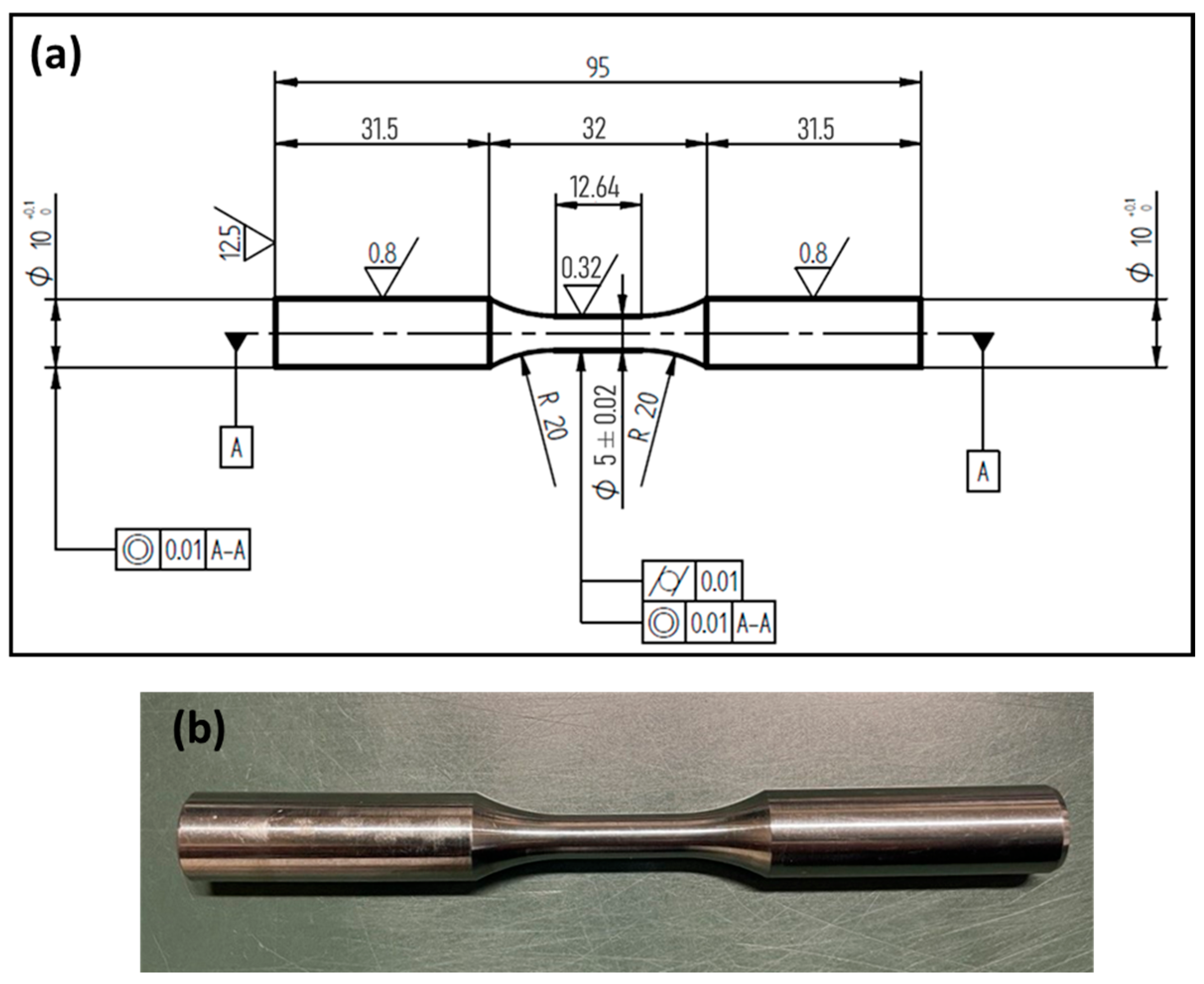
2.3. Fatigue, Hardness Tests, and Fractographic Analyses

High-cycle fatigue strength was evaluated through fully reversed (R = −1) rotating–bending tests conducted in a four-point configuration machine (RB35, Italsigma, Forlì, Italy), according to the ISO 1143:2021 standard. The tests were performed at a frequency of 50 Hz, with a run-out limit of 2 × 10⁶ cycles. Fatigue strength at a 50% probability of failure (σd,50%) and the associated standard deviation (σγ) were determined using the staircase method (ISO 12107:2012 [31]). Based on preliminary tests, a stress increment of 20 MPa (approximately 5% of the estimated fatigue strength) was selected, and 15 specimens were tested for each heat treatment condition. Vickers hardness measurements were performed on the grip sections of the fatigue specimens using a 30 kg load and a 15 s dwell time to ensure consistency in hardness across all the samples. For both treatment conditions, the values were obtained by averaging 5 measurements performed on two different samples.
All the run-out specimens were subsequently retested until failure. Fractographic analyses were conducted using the FEG-SEM to identify crack nucleation sites, dominant failure mechanisms, and the size and nature of the defect responsible for initiation, referred to as the “killer defect”. For each specimen tested, the stress range (Δσ)—a function of the maximum (σmax) and minimum (σmin) stress—and the stress intensity factor range (ΔK) at the crack tip were determined, calculated using Equations (1) and (2), respectively. Since the tests were conducted under symmetric alternating load conditions (R = −1), σmax and σmin are equal in magnitude and opposite in sign, and Δσ is twice the alternating stress (σa). The stress intensity factor is a function of the stress range, the critical defect size (in terms of √area, also known as the Murakami parameter), and the defect’s location (where coefficient C is 0.5 for internal defects or 0.65 for surface defects) [26,32,33].
σ = σ m a x σ m i n = 2 σ a ,
K = C · σ · π · a r e a ,
KT diagrams were developed based on the fracture surface analysis data, in accordance with established methodologies for additively manufactured alloys [26]. These diagrams plot Δσ and ΔK as functions of the √area, establishing a correlation between high-cycle fatigue strength and the critical defect size for the Ti6246 alloy. The diagrams include both run-out conditions, marked with “O”, and failure conditions, indicated by “X”. The data points on the KT diagram were then fitted using the El-Haddad model [34]. This model generates threshold curves that identify regions of failure (above the curve) from non-failure (below the curve). Specifically, the obtained curves are described by Equations (3)–(5), which represent the relationship between the fatigue threshold stress range (Δσth), the threshold crack propagation resistance range (ΔKth), and the critical defect size (√area):
σ t h a r e a = σ t h , 0 a r e a 0 a r e a + a r e a 0 ,
K t h a r e a = K t h , l c a r e a a r e a + a r e a 0 ,
a r e a 0 = 1 π · K t h , l c Y · σ t h , 0 2
Δσth,0 represents the limiting stress range for defect-free specimens; ΔKth,lc represents the resistance limit to long crack (macrocrack) propagation; and √area0 is a modeling parameter proportional to the critical crack length, distinguishing short from long cracks, and it is dependent on Δσth,0 and ΔKth,lc, which best fit the experimental data.

3. Results and Discussion

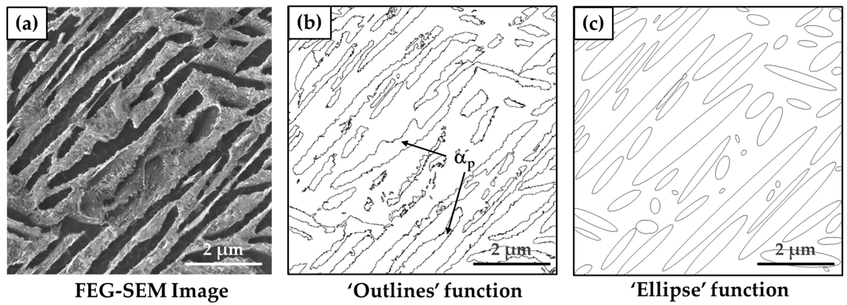
3.1. Microstructural Characterization

Figure 4a presents a representative OM image showing small, circular defects indicative of gas porosity (marked by arrows) and a larger, irregular defect characteristic of a LoF, further detailed in the FEG-SEM image in Figure 4b. Porosity analyses for the AN875 and STA825 samples revealed no significant deviations from the previously reported values in [23]. The average density measurements are consistent with prior results, with densities of 99.81 ± 0.05% and 99.87 ± 0.09%, respectively.
The defect size distribution, derived from image analysis of OM micrographs, is illustrated in Figure 5a. The data represents the number of defects per unit area as a function of the square root of the defect area. The accompanying table reports the 50th (D50) and 90th (D90) percentiles of defect size and the maximum defect size (Dmax). In the AN875 heat-treated alloy, a lower relative frequency of defects is observed, accompanied by a higher proportion of larger defects compared to the STA825 condition. This behavior is attributed to the higher solution treatment temperature used in the AN875 process, which may promote slight growth of gas-induced porosities, as evidenced in previous works on AM-processed alloys [35,36,37]. Nonetheless, the variation in defect size is limited to just a few microns and is considered negligible in terms of its impact on the mechanical performance of the material, particularly its fatigue behavior.
Figure 5b shows a schematic representation of the cross-sections analyzed for each sample.
Figure 6 presents FEG-SEM micrographs of chemically etched samples following heat treatment. Both conditions exhibit columnar prior β grains, generated from PBF-LB printing, and a bilamellar microstructure characterized by the formation of αs within the β phase, located between αp lamellae. However, the STA825 condition exhibits a significantly finer arrangement of both αp and αs lamellae compared to the AN875 condition. These microstructural differences arise from the distinct solution treatment parameters and cooling rates applied in each heat treatment, which influence phase transformation kinetics and lamellar refinement. As reported by Galarraga et al. [38], the growth of the α phase is primarily governed by two factors: solution temperature and cooling rate. Higher solution temperatures, approaching the β-transus, combined with slower cooling rates, promote coarsening of αp lamellae. In the AN875 condition, the microstructure consists of large αp lamellae with rounded tips, along with finer αs lamellae that nucleate within the β phase (αs+β) separating the αp lamellae (Figure 6d). However, the αs fraction is relatively low and inhomogeneously distributed. During isothermal holding at 875 °C, accelerated diffusion processes drive the coarsening of αp. This effect is further amplified by slow furnace cooling, which promotes additional coarsening of αp and the formation and consequent coarsening of αs lamellae [39]. Conversely, the STA825 condition exhibits a finer bilamellar microstructure with a significantly reduced size and volume fraction of αp lamellae, primarily influenced by the solution temperature (825 °C) and holding time. Additionally, αs lamellae are extremely fine and uniformly distributed within the β phase (αs + β). Rapid water quenching, in fact, inhibits diffusive transformations, preserving the αp amount achieved at 825 °C and leading to the formation of metastable β phase, as discussed by the authors in [23]. The subsequent aging process induces transformation of the metastable β phase, leading to the formation of a finely distributed αs lamellar structure within the β phase, as indicated in Figure 6b, and the precipitation of very fine strengthening α2 (Ti3Al) within αp, in agreement with the results of the XRD analysis reported in our previous study [23]. Similar findings for α-β alloys containing a minimum of 6% Al after STA heat treatment are also described in [38,40,41,42].
Table 4 summarizes the key microstructural characteristics, including the αp lamellae content and thickness, for each heat treatment condition. These values agree with those obtained during the heat treatment optimization phase [23].

3.2. Fatigue Behavior

The results of the fatigue tests are reported in Table 5. The STA825 samples (HV30 = 425 ± 5) exhibited higher fatigue strength compared to the AN875 ones (HV30 = 351 ± 9), with the 50% probability of failure (σd,50%) being approximately 25% higher (474 ± 15 MPa vs. 382 ± 15 MPa). For both heat treatment conditions, σd,50% was found to be approximately 35–36% of the ultimate tensile strength (UTS) (Table 5), highlighting a correlation between the static and fatigue properties of the alloy, regardless of the heat treatment conditions.
This observation confirms the soundness of the design strategy employed for the STA825 heat treatment. Specifically, the STA825 treatment offers enhanced fatigue resistance over the conventional AN875 condition due to the following: (i) enhanced static strength, resulting from the synergistic strengthening effect of a refined and homogeneously distributed bilamellar architecture (comprising αs lamellae and a retained β phase within the interlamellar regions) and the precipitation of Ti3Al intermetallics during the aging stage; (ii) improved resistance to early-stage fatigue crack initiation and propagation, particularly along αp/(αs + β) interfaces, due to the presence of fine αs lamellae, as confirmed by previous studies [14,43]; and (iii) an increased capability to deflect or arrest macrocrack propagation, attributed to the presence of fine and hardened primary α lamellae, which outperform the coarser counterparts typically formed under the AN875 regime.
Figure 7a,b shows low-magnification images of fracture surfaces of the different fatigue samples, highlighting regions characterized by stable fatigue crack propagation and final overload fractures. For both treatment conditions, nucleation was observed to occur superficially or sub-superficially, mainly from Lof defects, as visible in high-magnification images (Figure 7c,d).
When nucleation occurs from subsurface killer defects, a low-speed crack propagation zone (LSP) and a high-speed crack propagation zone (HSP) can be identified (Figure 8a). The LSP zone (Figure 8b) can be associated with fish-eye-like crack propagation, as it exhibits an alternating distribution of parallel bright strips and dark grooves, a phenomenon termed the “mackerel pattern”. This pattern was identified by Gao et al. for Ti64 [44] and Ti6.5Al-3.5Mo.1.5Zr-0.3Si (TC11) [45] alloys. The mackerel pattern can be attributed to the difficulty encountered by the crack during its early growth stages in propagating along the fine αp/(αs + β) interface [45]. This effect is much more readily identifiable in the STA825 sample because the crack propagates with greater difficulty due to the presence of uniformly distributed αs lamellae within the β phase. According to Lütjering et al. [40], αs lamellae are difficult to deform plastically and can be considered undeformable. Therefore, their presence induces strong resistance to crack propagation, resulting in the formation of grooves and strips within the LSP [44]. In contrast, the HSP in Figure 8c zone exhibits a different morphology, characterized by the presence of tearing ridges and quasi-cleavage facets. This phenomenon is not observed when the crack nucleates and propagates from surface defects, as shown in Figure 8d. In such cases, only HSP zones can be detected, exhibiting quasi-cleavage propagation, characterized by tearing ridges and the presence of microcracks both at the crack tip (Figure 8e) and further along the propagation path (Figure 8f), in which the fatigue striations typical of a fracture under cyclic loading are detectable also. These observations agree with the findings of Li et al. [46], who attributed these peculiar fracture surface morphologies to differences in the ΔK values associated with fracture initiation at the surface versus the subsurface.
Micrographs of the overload fracture zones (Figure 9) reveal a ductile morphology, characterized by the presence of large dimples for the AN875 condition and shallow dimples for the STA825, consistent with the higher elongation to failure of the AN875 alloy than the STA825 alloy and the fracture surfaces observed in the tensile specimens documented in [23].
Figure 10a,b present the KT diagrams. These diagrams illustrate, respectively, the stress range as a function of the defect size (√area; Δσ) and the stress intensity factor range versus the defect size (√area; ΔK), complete with their respective El-Haddad best-fit curves. The best-fit parameters derived from the El-Haddad model for the two tested conditions are listed in Table 6.
The results obtained from the KT diagrams revealed that the Δσth,0 and ΔKth,lc resistances were 19 and 77% higher, respectively, for the STA825 sample compared to the AN875. For samples produced with additive manufacturing technologies, the latter value is particularly significant since crack nucleation almost always originates from pre-existing defects generated during the process. This confirms the positive effect of the fine bilamellar microstructure on the fatigue performance of the alloy, resulting from the synergistic combination of high tensile strength, good ductility, and enhanced resistance to crack propagation.
Although the heat-treated PBF-LB Ti6246 alloy can achieve a higher UTS compared to its wrought counterpart (1327 MPa [23] vs. 1279 MPa [10]), its fatigue performance is significantly lower due to the presence of defects, such as LoF and pores [14,21], which act as preferential sites for crack initiation. In contrast, in conventionally processed alloys, cracks generally initiate within large α grains or α grain clusters, where localized microstructural features promote irreversible slip accumulation [43], rather than from manufacturing-induced defects. Peters et al. [12] reported that the STA-treated alloy with a fine bimodal microstructure exhibited HCF strength at stress levels up to 625 MPa, approximately 37 and 21% higher than the AN875 and STA825 conditions, respectively, due to the different crack initiation mechanisms.
Figure 11 provides a comparative analysis of the fatigue behavior of the Ti6246 alloy produced via PBF-LB in this study, the same alloy manufactured through conventional methods, and the Ti64 alloy fabricated with PBF-LB technology and subjected to different heat treatments. The reported data for the Ti64 alloy refer to tests conducted under a stress ratio of R = −1, using surface-polished specimens, consistent with the testing conditions applied to the Ti6246 alloy in this work. When comparing the PBF-LB STA825 Ti6246 with the PBF-LB Ti64 alloy, the STA825 Ti6246 shows superior fatigue performance regardless of the heat treatment conditions, as highlighted in Figure 10.

4. Conclusions

This study focused on assessing the effect of heat treatments and the resulting microstructures on the fatigue resistance of a Ti6246 alloy produced via PBF-LB. Two heat treatment conditions were investigated: α+β annealing at 875 °C for 2 h (AN875) and α+β solution treatment at 825 °C, followed by water quenching and aging at 500 °C for 3 h (STA825). Based on microstructural characterization, fatigue testing, and fractographic analysis, the following conclusions can be drawn:
(i)
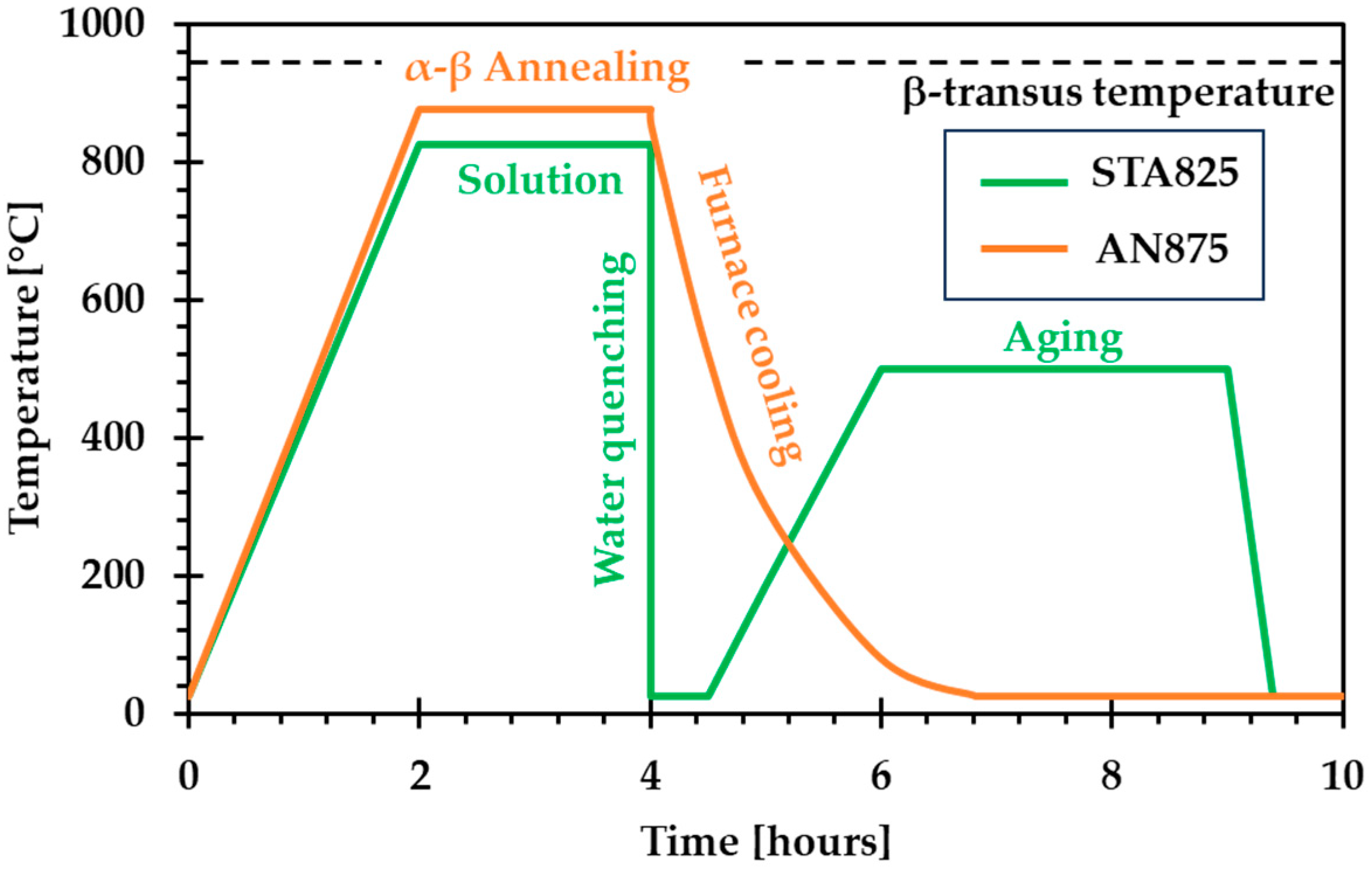
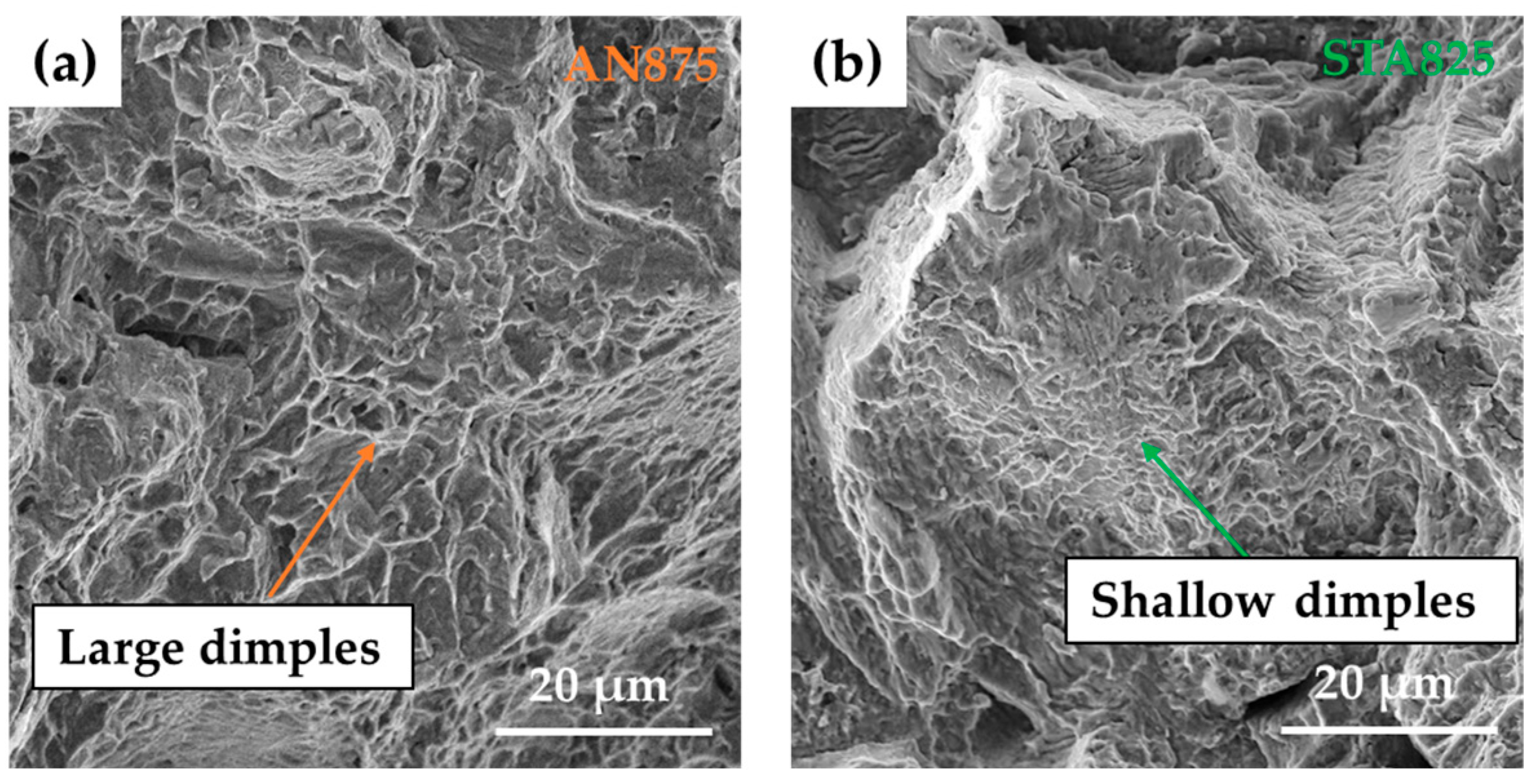
The AN875-treated samples exhibited the lowest fatigue strength (σd,50% = 382 ± 15 MPa), primarily due to the low mechanical properties associated with significant microstructural coarsening caused by the high annealing temperature, slow furnace cooling rate, and the absence of strengthening precipitates. The low strength primarily affected crack initiation, while the coarse primary α (αp) phase facilitated crack propagation.
(ii)
The STA825-treated samples demonstrated the highest fatigue strength (σd,50% = 474 ± 15 MPa), corresponding to an improvement of nearly 25% over the AN875 condition. This enhancement is attributed to the presence of strengthening precipitates, the refinement of αp lamellae, and the formation of ultrafine, homogeneously distributed secondary α lamellae within the β phase (αs + β), which hinder fatigue crack nucleation and early-stage propagation.
(iii)
Both heat treatment conditions exhibited a similar σD,50%/UTS ratio, ranging between 35% and 36%, demonstrating a clear correlation between static and fatigue properties.
(iv)
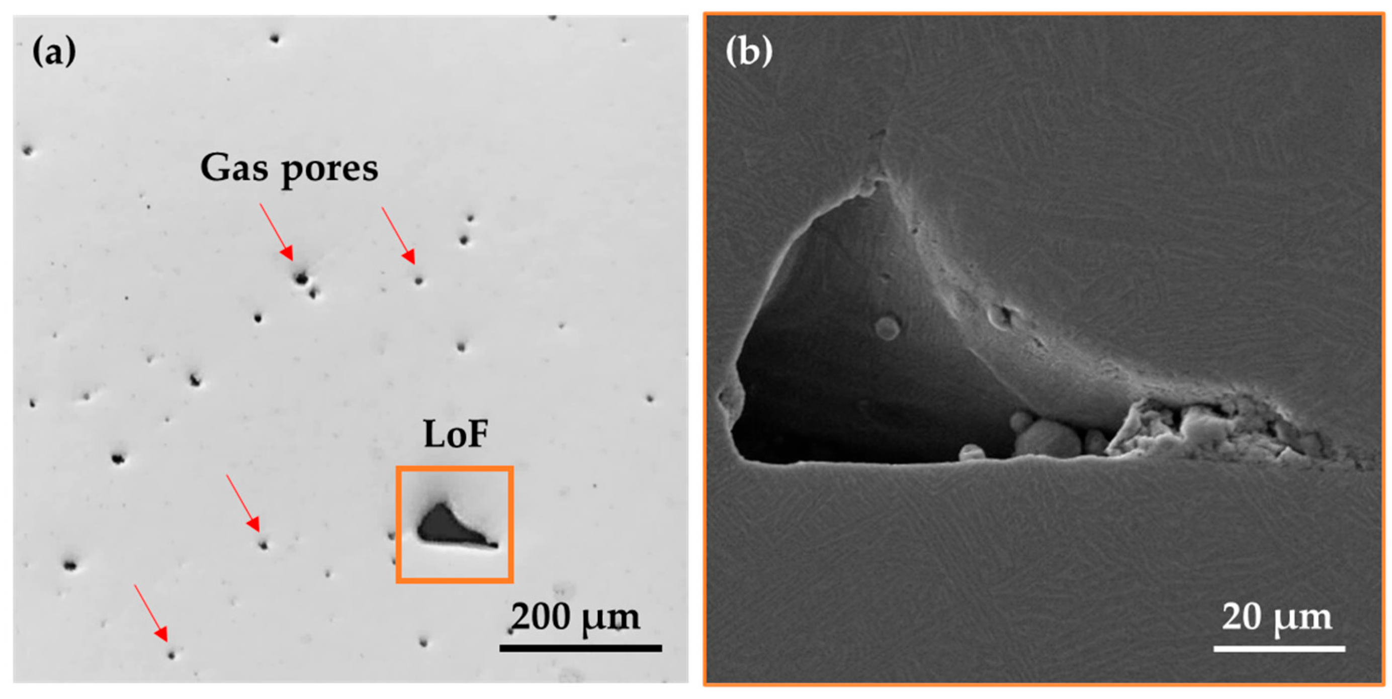
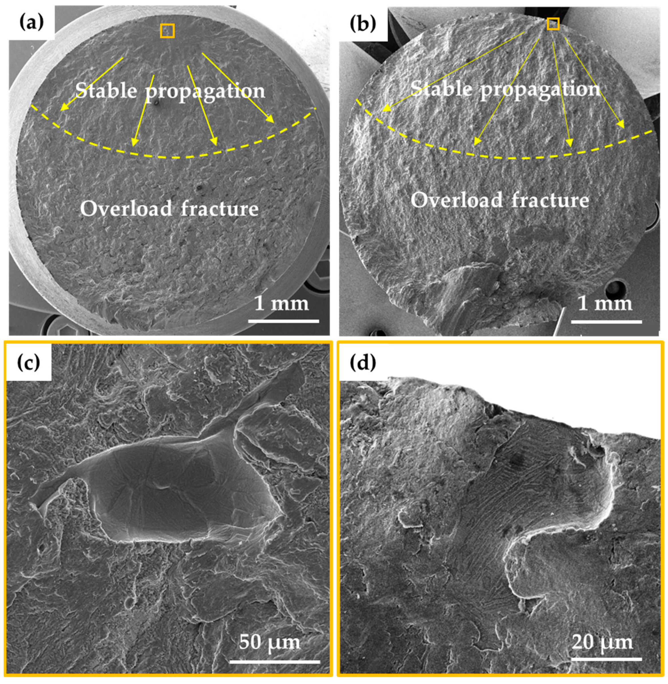
In both heat treatment conditions, fatigue crack nucleation consistently occurred at surface or subsurface lack of fusion defects. These process-induced defects represent the primary limiting factor in the fatigue performance of PBF-BF Ti6246 compared to its conventionally produced counterpart.
(v)
Crack propagation behavior was strongly influenced by defect location. Subsurface defects triggered an initial low-speed propagation (LSP) region characterized by a “mackerel pattern”, likely due to the high microcrack growth resistance in the early propagation stage at αp/(αs + β) interfaces. This was followed by a high-speed propagation (HSP) region exhibiting quasi-cleavage fracture. In contrast, surface-initiated cracks propagated directly through quasi-cleavage mechanisms from the crack tip. Fatigue striations were observed in the HSP zone.
(vi)
El-Haddad’s best-fit parameters derived from the Kitagawa–Takahashi diagrams confirmed the beneficial role of the fine bilamellar microstructure of the STA825 condition in enhancing fatigue performance, with an increase of 19% in the intrinsic fatigue limit (Δσth,0) and 77% in the threshold stress intensity factor (ΔKth,lc).
(vii)
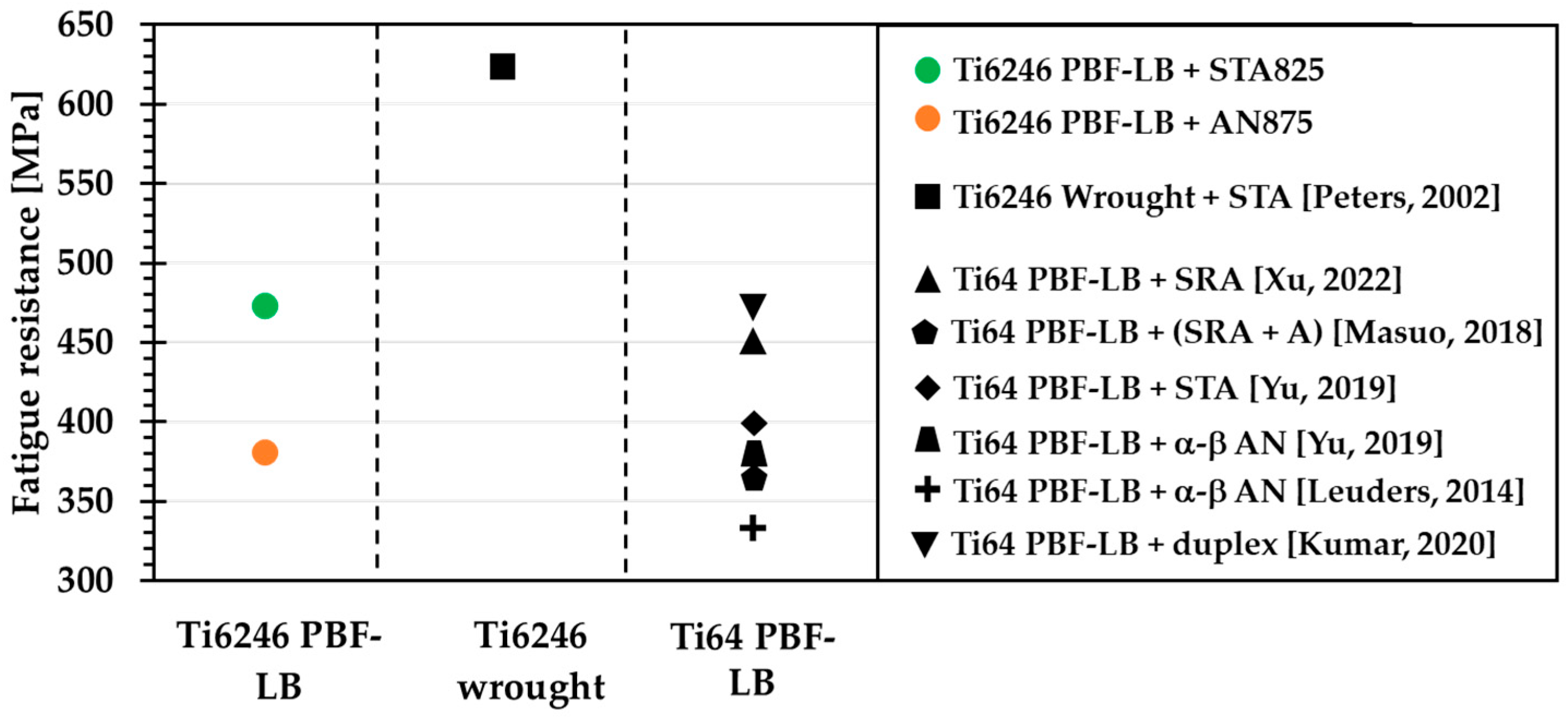
The STA825-treated Ti6246 alloy exhibited superior fatigue strength compared to PBF-LB Ti-6Al-4V subjected to various heat treatments.
This study addresses a critical gap in the current literature concerning the influence of heat treatments on the microstructure and fatigue performance of Ti-6Al-2Sn-4Zr-6Mo (Ti6246) alloy processed via Powder Bed Fusion—Laser Beam (PBF-LB). Future investigations will focus on the role of surface finishing and Hot Isostatic Pressing (HIP) as potential post-processing strategies to mitigate the detrimental effects of process-induced defects and further improve fatigue resistance. Expanding the knowledge base on this alloy and optimizing its post-processing treatments are essential steps toward enabling its broader adoption in high-performance structural applications, such as fan blades, engine shafts, or connecting rods.

Author Contributions

Conceptualization, G.P. and A.M. (Alessandro Morri); software G.P.; methodology, G.P. and A.M. (Alessandro Morri); validation, A.M. (Alessandro Morri) and G.P.; formal analysis, G.P. and A.M. (Alessandro Morri); investigation, G.P.; resources, A.M. (Alessandra Martucci) and M.L.; data curation, G.P.; writing—original draft preparation, G.P.; writing—review and editing, A.M. (Alessandro Morri), L.C., A.M. (Alessandra Martucci), and M.L.; visualization, L.C. and A.M. (Alessandro Morri); supervision, L.C.; project administration, A.M. (Alessandro Morri) and L.C.; funding acquisition, L.C. All authors have read and agreed to the published version of the manuscript.

Funding

This study was financed by the European Union-NextGenerationEU (National Sustainable Mobility Center CN00000023, Italian Ministry of University and Research Decree n. 1033-17/06/2022, Spoke 11-Innovative Materials & Lightweighting). The opinions expressed are those of the authors only and should not be considered as representative of the European Union or the European Commission’s official position. Neither the European Union nor the European Commission can be held responsible for them.

Data Availability Statement

The data presented in this study are available on request from the corresponding author. (Due to industrial secrecy, the data are not publicly released. However, they can be shared upon specific request).

Conflicts of Interest

The authors declare no conflicts of interest.

Abbreviations

The following abbreviations are used in this manuscript:
AMadditive manufacturing
PBF-LBPowder Bed Fusion–Laser Beam
HCFhigh cycle fatigue
STAsolution treating and aging
LoFlack of fusion
KTKitagawa–Takahashi
GD-OESGlow Discharge Optical Emission Spectroscopy
OMoptical microscope
FEG-SEMField Emission Gun–Scanning Electron Microscope
LSPlow-speed propagation
HSPhigh-speed propagation

References

  1. Zhao, Q.; Sun, Q.; Xin, S.; Chen, Y.; Wu, C.; Wang, H.; Xu, J.; Wan, M.; Zeng, W.; Zhao, Y. High-strength titanium alloys for aerospace engineering applications: A review on melting-forging process. Mater. Sci. Eng. A 2022, 845, 143260. [Google Scholar] [CrossRef]
  2. Nyamekye, P.; Rahimpour Golroudbary, S.; Piili, H.; Luukka, P.; Kraslawski, A. Impact of additive manufacturing on titanium supply chain: Case of titanium alloys in automotive and aerospace industries. Adv. Ind. Manuf. Eng. 2023, 6, 100112. [Google Scholar] [CrossRef]
  3. Liu, S.; Shin, Y.C. Additive manufacturing of Ti6Al4V alloy: A review. Mater. Des. 2019, 164, 107552. [Google Scholar] [CrossRef]
  4. Yang, N.; Shan, M.; Shi, G.; Guo, H.; Xiong, S.; Luo, M.; Zhang, D.; Cui, M. Physicochemical State Classification of Heat-treated TC4 Samples Based on Laser-induced Breakdown Spectroscopy (LIBS). At. Spectrosc. 2024, 45, 324–335. [Google Scholar] [CrossRef]
  5. Li, G.; Chandra, S.; Rahman Rashid, A.; Palanisamy, S.; Ding, S. Machinability of additively manufactured titanium alloys: A comprehensive review. J. Manuf. Process. 2022, 75, 72–99. [Google Scholar] [CrossRef]
  6. Carrozza, A.; Aversa, A.; Fino, P.; Lombardi, M. A study on the microstructure and mechanical properties of the Ti-6Al-2Sn-4Zr-6Mo alloy produced via Laser Powder Bed Fusion. J. Alloys Compd. 2021, 870, 159329. [Google Scholar] [CrossRef]
  7. Herzog, D.; Seyda, V.; Wycisk, E.; Emmelmann, C. Additive manufacturing of metals. Acta Mater. 2016, 117, 371–392. [Google Scholar] [CrossRef]
  8. Rani, S.U.; Kesavan, D.; Kamaraj, M. Evaluation of influence of microstructural features of LPBF Ti-6Al-4 V on mechanical properties for an optimal strength and ductility. J. Alloys Compd. 2023, 960, 170575. [Google Scholar] [CrossRef]
  9. Yumak, N.; Aslantaş, K. A review on heat treatment efficiency in metastable β titanium alloys: The role of treatment process and parameters. J. Mater. Res. Technol. 2020, 9, 15360–16280. [Google Scholar] [CrossRef]
  10. Alluaibi, M.H.I.; Cojocaru, E.M.; Rusea, A.; Șerban, N.; Coman, G.; Cojocaru, V.D. Microstructure and mechanical properties evolution during solution and ageing treatment for a hot deformed, above β-transus, Ti-6246 alloy. Metals 2020, 10, 1114. [Google Scholar] [CrossRef]
  11. Sauer, C.; Lütjering, G. Processing, Microstructure and Properties of Ti-6246. 1999. Available online: https://cdn.ymaws.com/titanium.org/resource/resmgr/ZZ-WTCP1999-VOL1/1999_Vol.1-4-Processing,_Mic.pdf (accessed on 1 April 2024).
  12. Peters, J.O.; Lütjering, G.; Nalla, R.K.; Altenberger, I.; Ritchie, R.O. High-Cycle Fatigue of Beta Titanium Alloys. 2002. Available online: https://www2.lbl.gov/ritchie/Library/poster/1_Fatigue2002-HCFofBetaTitaniumAlloys.pdf (accessed on 6 February 2025).
  13. Jeong, D.; Kwon, Y.; Goto, M.; Kim, S. High cycle fatigue and fatigue crack propagation behaviors of β-annealed Ti-6Al-4V alloy. Int. J. Mech. Mater. Eng. 2017, 12, 1. [Google Scholar] [CrossRef]
  14. Liu, Z.; Dash, S.S.; Zhang, J.; Lyu, T.; Lang, L.; Chen, D.; Zou, Y. Fatigue crack growth behavior of an additively manufactured titanium alloy: Effects of spatial and crystallographic orientations of α lamellae. Int. J. Plast. 2024, 172, 103819. [Google Scholar] [CrossRef]
  15. Yu, H.; Li, F.; Wang, Z.; Zeng, X. Fatigue performances of selective laser melted Ti-6Al-4V alloy: Influence of surface finishing, hot isostatic pressing and heat treatments. Int. J. Fatigue 2019, 120, 175–183. [Google Scholar] [CrossRef]
  16. Xu, Z.; Liu, A.; Wang, X. Fatigue performance differences between rolled and selective laser melted Ti6Al4V alloys. Mater. Charact. 2022, 189, 111963. [Google Scholar] [CrossRef]
  17. Sing, S.L.; Huang, S.; Yeong, W.Y. Additive Manufacturing of Titanium and Titanium Alloy Biomedical De-vices. In Additive Manufacturing in Biomedical Applications; ASM International: West Conshohocken, PA, USA, 2022; pp. 192–200. [Google Scholar] [CrossRef]
  18. Leuders, S.; Thöne, M.; Riemer, A.; Niendorf, T.; Tröster, T.; Richard, H.; Maier, H. On the mechanical behaviour of titanium alloy TiAl6V4 manufactured by selective laser melting: Fatigue resistance and crack growth performance. Int. J. Fatigue 2013, 48, 300–307. [Google Scholar] [CrossRef]
  19. Zhang, X.; Xue, K.; Liu, L.; Xiao, J.; Liu, J.; Jin, F.; Luo, M.; Zhan, M.; Li, H. Effect of electrical pulse treatment on the microstructural and mechanical responses of heterogeneous linear friction welded TC17/TC4 dissimilar joint. J. Mater. Res. Technol. 2025, 35, 1–12. [Google Scholar] [CrossRef]
  20. Li, P.; Warner, D.; Fatemi, A.; Phan, N. Critical assessment of the fatigue performance of additively manufactured Ti-6Al-4V and perspective for future research. Int. J. Fatigue 2016, 85, 130–143. [Google Scholar] [CrossRef]
  21. Butt, M.M.; Laieghi, H.; Kvvssn, V.; Uddin, Z.; Shah, M.; Ansari, P.; Salamci, M.U.; Patterson, A.E.; Kizil, H. Fatigue performance in additively manufactured metal alloys. Prog. Addit. Manuf. 2024, 10, 1809–1841. [Google Scholar] [CrossRef]
  22. Wycisk, E.; Solbach, A.; Siddique, S.; Herzog, D.; Walther, F.; Emmelmann, C. Effects of defects in laser additive manufactured Ti-6Al-4V on fatigue properties. Phys. Procedia 2014, 56, 371–378. [Google Scholar] [CrossRef]
  23. Pirro, G.; Martucci, A.; Morri, A.; Lombardi, M.; Ceschini, L. A novel solution treatment and aging for powder bed fusion-laser beam Ti-6Al-2Sn-4Zr-6Mo alloy: Microstructural and mechanical characterization. Int. J. Miner. Met. Mater. 2025, 32, 414–424. [Google Scholar] [CrossRef]
  24. Carrozza, A.; Aversa, A.; Fino, P.; Lombardi, M. Towards customized heat treatments and mechanical properties in the LPBF-processed Ti-6Al-2Sn-4Zr-6Mo alloy. Mater. Des. 2022, 215, 110512. [Google Scholar] [CrossRef]
  25. Cao, F.; Zhang, T.; Ryder, M.A.; Lados, D.A. A Review of the Fatigue Properties of Additively Manufactured Ti-6Al-4V. JOM 2018, 70, 349–357. [Google Scholar] [CrossRef]
  26. Zanni, M.; Di Egidio, G.; Tonelli, L.; Morri, A.; Ceschini, L. An analysis of the influence of heat treatments and surface finishing conditions on the high cycle fatigue behaviour of W360 hot work tool steel produced by Powder Bed Fusion–Laser Beam. Mater. Sci. Eng. A 2025, 932, 148237. [Google Scholar] [CrossRef]
  27. Lampman, S. Wrought Titanium and Titanium Alloys. In Properties and Selection: Nonferrous Alloys and Special-Purpose Materials; ASM International: West Conshohocken, PA, USA, 1990; pp. 592–633. [Google Scholar] [CrossRef]
  28. BS ISO 1143:2021; Rotating Bar Bending Fatigue Testing. European Standards: Bruxelles, Belgium, 2021.
  29. Gammon, L.M.; Briggs, R.D.; Packard, J.M.; Batson, K.W.; Boyer, R.; Domby, C.W. Metallography and Microstructures of Titanium and Its Alloys. In Metallography and Microstructures; ASM International: West Conshohocken, PA, USA, 2004; pp. 899–917. [Google Scholar] [CrossRef]
  30. Schneider, C.A.; Rasband, W.S.; Eliceiri, K.W. NIH Image to ImageJ: 25 years of image analysis. Nat. Methods 2012, 9, 671–675. [Google Scholar] [CrossRef]
  31. ISO 12107:2012; Metallic Materials-Fatigue Testing-Statistical Planning and Analysis of Data. European Standards: Bruxelles, Belgium, 2012.
  32. Murakami, Y.; Masuo, H.; Tanaka, Y.; Nakatani, M. Defect Analysis for Additively Manufactured Materials in Fatigue from the Viewpoint of Quality Control and Statistics of Extremes. Procedia Struct. Integr. 2019, 19, 113–122. [Google Scholar] [CrossRef]
  33. Murakami, Y.; Beretta, S. Small Defects and Inhomogeneities in Fatigue Strength: Experiments, Models and Statistical Implications. Extremes 1999, 2, 123–147. [Google Scholar] [CrossRef]
  34. El Haddad, M.H.; Smith, K.N.; Topper, T.H. Fatigue crack propagation of short cracks. J. Eng. Mater. Technol. 1979, 101, 42–46. [Google Scholar] [CrossRef]
  35. Bu, H.; Chen, L.; Duan, Y. Effect of Solution Heat Treatment on the Porosity Growth of Nickel-Based P/M Superalloys. Metals 2022, 12, 1973. [Google Scholar] [CrossRef]
  36. Di Egidio, G.; Ceschini, L.; Morri, A.; Martini, C.; Merlin, M. A Novel T6 Rapid Heat Treatment for AlSi10Mg Alloy Produced by Laser-Based Powder Bed Fusion: Comparison with T5 and Conventional T6 Heat Treatments. Metall. Mater. Trans. B Process Metall. Mater. Process. Sci. 2022, 53, 284–303. [Google Scholar] [CrossRef]
  37. Tammas-Williams, S.; Withers, P.; Todd, I.; Prangnell, P. Porosity regrowth during heat treatment of hot isostatically pressed additively manufactured titanium components. Scr. Mater. 2016, 122, 72–76. [Google Scholar] [CrossRef]
  38. Galarraga, H.; Warren, R.J.; Lados, D.A.; Dehoff, R.R.; Kirka, M.M.; Nandwana, P. Effects of heat treatments on microstructure and properties of Ti-6Al-4V ELI alloy fabricated by electron beam melting (EBM). Mater. Sci. Eng. A 2017, 685, 417–428. [Google Scholar] [CrossRef]
  39. Ter Haar, G.M.; Becker, T.H. Selective laser melting produced Ti-6Al-4V: Post-process heat treatments to achieve superior tensile properties. Materials 2018, 11, 146. [Google Scholar] [CrossRef]
  40. Lutjering, G.; Williams, J.C. Titanium, 2nd ed.; Springer: Berlin/Heidelberg, Germany, 2007; Chapter 7; pp. 302–314. [Google Scholar]
  41. Vrancken, B.; Thijs, L.; Kruth, J.-P.; Van Humbeeck, J. Heat treatment of Ti6Al4V produced by Selective Laser Melting: Microstructure and mechanical properties. J. Alloys Compd. 2012, 541, 177–185. [Google Scholar] [CrossRef]
  42. Yu, J.; Yin, Z.; Huang, Z.; Zhao, S.; Huang, H.; Yu, K.; Zhou, R.; Xiao, H. Effect of Aging Treatment on Microstructural Evolution and Mechanical Properties of the Electron Beam Cold Hearth Melting Ti-6Al-4V Alloy. Materials 2022, 15, 7122. [Google Scholar] [CrossRef]
  43. Szczepanski, C.; Jha, S.; Larsen, J.; Jones, J. Microstructural influences on very-high-cycle fatigue-crack initiation in Ti-6246. Metall. Mater. Trans. A Phys. Metall Mater Sci. 2008, 39, 2841–2851. [Google Scholar] [CrossRef]
  44. Gao, T.; Zhao, X.; Xue, H.; Sun, Z. Characteristics and micromechanisms of fish-eye crack initiation of a Ti-6Al-4V alloy in very high cycle fatigue regime. J. Mater. Res. Technol. 2022, 21, 3140–3153. [Google Scholar] [CrossRef]
  45. Gao, T.; Xue, H.; Sun, Z.; Retraint, D. Investigation of crack initiation mechanism of a precipitation hardened TC11 titanium alloy under very high cycle fatigue loading. Mater. Sci. Eng. A 2020, 776, 138989. [Google Scholar] [CrossRef]
  46. Li, W.; Zhao, H.; Nehila, A.; Zhang, Z.; Sakai, T. Very high cycle fatigue of TC4 titanium alloy under variable stress ratio: Failure mechanism and life prediction. Int. J. Fatigue 2017, 104, 342–354. [Google Scholar] [CrossRef]
  47. Masuo, H.; Tanaka, Y.; Morokoshi, S.; Yagura, H.; Uchida, T.; Yamamoto, Y.; Murakami, Y. Influence of defects, surface roughness and HIP on the fatigue strength of Ti-6Al-4V manufactured by additive manufacturing. Int. J. Fatigue 2018, 117, 163–179. [Google Scholar] [CrossRef]
  48. Leuders, S.; Lieneke, T.; Lammers, S.; Tröster, T.; Niendorf, T. On the fatigue properties of metals manufactured by selective laser melting—The role of ductility. J. Mater. Res. 2014, 29, 1911–1919. [Google Scholar] [CrossRef]
  49. Kumar, P.; Ramamurty, U. High cycle fatigue in selective laser melted Ti-6Al-4V. Acta Mater. 2020, 194, 305–320. [Google Scholar] [CrossRef]
Figure 1. Representation of STA825 (green) and AN875 (orange) thermal cycles.
Metals 15 00849 g001
Figure 2. The geometry and dimensions [mm] (a) and an image of the fatigue samples (b) according to BS ISO 1143:2021.
Metals 15 00849 g002
Figure 3. FEG-SEM microstructure (a) for image analysis made by using the ‘Outlines’ Function (b) to determine the αp content and the ‘Ellipse’ Function (c) to quantify the αp lamella thickness.
Metals 15 00849 g003
Figure 4. An OM image of a Ti6246 sample showing gas porosities (indicated by red arrows) and a larger LoF defect (a), with a corresponding high-magnification FEG-SEM image (b).
Metals 15 00849 g004
Figure 5. The relative and cumulative frequency distributions of defect sizes (in terms of the square root of the area) (a) obtained from image analysis on OM micrographs of polished cross sections (b).
Metals 15 00849 g005
Figure 6. Low- and high-magnification FEG-SEM images of STA825 (a,b) and AN875 microstructures (c,d). The yellow dotted lines and the white arrows highlight, respectively, the columnar prior β-grain boundaries and the principal microstructural features.
Metals 15 00849 g006
Figure 7. Low-magnification (a,b) FEG-SEM images of different fracture surfaces with a focus on crack nucleation sites originating from sub-superficial (c) or superficial LoFs (d). The yellow arrows and dotted lines highlight, respectively, the stable propagation direction and the end of the stable propagation zone.
Metals 15 00849 g007
Figure 8. Crack propagation from subsurface defects (a), characterized by LSP (b) and HSP (c) zones, and from surface defects (d) with quasi-cleavage zones both at the crack tip (e) and in the propagation zone (f).
Metals 15 00849 g008
Figure 9. High-magnification images of the overload fracture zone of the specimens AN875 (a) and STA825 (b).
Metals 15 00849 g009
Figure 10. KT diagrams of the stress range (Δσ) (a) and the stress intensity factor (ΔK) (b) as a function of the defect size (√area). “X” indicates failed specimens, while “O” refers to run-out specimens.
Metals 15 00849 g010
Figure 11. A comparison of the fatigue behavior of the following: (i) the Ti6246 alloy produced via PBF-LB in this study; (ii) the same alloy manufactured through conventional methods (Adapted from [12]); (iii) the Ti64 alloy fabricated with PBF-LB technology and subjected to various heat treatments, including Stress-Relieving Annealing (SRA) (Adapted from [16]), SRA and aging (SRA+A) (Adapted from [47]), α+β annealing (α-β AN) (Adapted from [15,48]), STA (Adapted from [15]), and double step annealing (duplex) (Adapted from [49]).
Metals 15 00849 g011
Table 1. Ti6246 alloy powders’ chemical composition (wt.%), as declared by the supplier and reported in the UNS R56260 standard.
Elements [% wt.]TiAlSnZrMoFeNOHOthers
Supplier compositionBal.5.961.853.675.890.030.010.120.002Total max < 0.30
Sample GD-OESBal.6.36 ± 0.132.06 ± 0.08 4.21 ± 0.095.85 ± 0.140.14 ± 0.01---Total: 0.20 ± 0.06
Standard compositionBal.5.5 ÷ 6.51.75 ÷ 2.253.5 ÷ 4.55.5 ÷ 6.5max 0.15max. 0.04max. 0.15max. 0.0125Each max 0.10
Total max 0.40
Table 2. PBF-LB scanning parameters for Ti6246 samples production.
Power [W]Scanning Speed [mm/s]Hatch
Distance [µm]
Layer
Thickness [µm]
Scanning StrategyPlatform
Temperature [°C]
190125010030Standard 67° EOS strategy100
Table 3. A summary of tensile properties for machined tensile specimens subjected to AN875 and STA825 treatments (Adapted from ref. [23]).
YS [MPa]UTS [MPa]EL [%]
STA8251118 ± 121327 ± 110.1 ± 0.4
AN875936 ± 91085 ± 122.3 ± 0.5
Table 4. Summary of microstructural features (αp lamellae content and thickness) for STA825 (measured after aging) and AN875 specimens.
αp Content [%]αp Thickness [μm]
STA82539.32 ± 0.690.29 ± 0.02
AN87569.99 ± 1.281.46 ± 0.10
Table 5. A summary of fatigue strength at the 50% failure probability (σd,50%) and standard deviation (σγ), and the σd,50%/UTS ratio of the investigated heat treatment conditions.
σ d , 50 % [MPa] σ γ [MPa] σ d , 50 % U T S [%]
STA825 4741535.7
AN875 3821535.2
Table 6. El-Haddad best-fit parameters for the analyzed conditions.
Δσth,0 [MPa]ΔKth,lc [MPa √m]√area0 [μm]
STA825117014.5116
AN8759808.253
Disclaimer/Publisher’s Note: The statements, opinions and data contained in all publications are solely those of the individual author(s) and contributor(s) and not of MDPI and/or the editor(s). MDPI and/or the editor(s) disclaim responsibility for any injury to people or property resulting from any ideas, methods, instructions or products referred to in the content.

