Article

Numerical Analysis of Aspect Ratio Effects on the Mechanical Behavior of Perforated Steel Plates

by
Thiago da Silveira
1,*,
Eduardo Araujo Crestani
2,
Elizaldo Domingues dos Santos
1 and
Liércio André Isoldi
1
1
Graduate Program in Ocean Engineering, Federal University of Rio Grande, Rio Grande 96201-900, RS, Brazil
2
Campus Alegrete, Federal University of Pampa, Alegrete 97546-550, RS, Brazil
*
Author to whom correspondence should be addressed.
Metals 2025, 15(7), 786; https://doi.org/10.3390/met15070786
Submission received: 10 May 2025 / Revised: 25 June 2025 / Accepted: 8 July 2025 / Published: 11 July 2025
(This article belongs to the Special Issue Fracture Mechanics of Metals (2nd Edition))

Abstract

Thin plates are commonly used in mechanical structures such as ship hulls, offshore platforms, aircraft, automobiles, and bridges. When subjected to in-plane compressive loads, these structures may experience buckling. In some applications, perforations are introduced, altering membrane stress distribution and buckling behavior. This study investigates the elasto-plastic buckling behavior of perforated plates using the Finite Element Method (FEM), Constructal Design (CD), and Exhaustive Search (ES) techniques. Simply supported thin rectangular plates with central elliptical perforations were analyzed under biaxial elasto-plastic buckling. Three shapes of holes were considered—circular, horizontal elliptical, and vertical elliptical—along with sixteen aspect ratios and two different materials. Results showed that higher yield stress leads to higher ultimate stress for perforated plates. Regardless of material, plates exhibited a similar trend: ultimate stress decreased as the aspect ratio dropped from 1.00 to around 0.40 and then increased from 0.35 to 0.25. A similar pattern was observed in the stress components along both horizontal (x) and vertical (y) directions, once the y-component became considerably higher than the x-component for the same range of 0.40 to 0.25. For longer plates, in general, the vertical elliptical hole brings more benefits in structural terms, due to the facility in the distribution of y-components of stress.

1. Introduction

Engineering must be in constant evolution and continuously updated. Every day, new materials and structural configurations are studied with the goal of improving the mechanical behavior of structures, enhancing safety, and reducing manufacturing costs. In industries focused on ship hulls, aircraft, or automobiles, in-plane biaxial compression is a common loading condition for plated structures. Therefore, understanding the behavior of thin plates under compressive loads is essential for project development.
Thin plates are characterized by having in-plane dimensions much larger than their thickness (t) [1]. When subjected to in-plane compressive loads, these structures may experience an instability phenomenon known as buckling [1]. However, according to the studies of [2,3,4], a thin plate does not collapse immediately after elastic buckling occurs, but it can sustain loads significantly higher than the critical load (Pcr) without experiencing excessive deformation. For that, the collapse is defined through the ultimate or post-critical load (Pu), which defines the maximum load that the structure can withstand during elasto-plastic buckling. Besides that, in some projects, perforations are introduced into plates for various purposes, such as inspection, assembly, pipe or cable accommodation, or weight reduction. The presence of these geometric discontinuities alters the mechanical behavior of the plate due to stress redistribution around the hole [5,6,7].
The analysis of elasto-plastic buckling of the perforated plates is not a simple task, but many studies have actually already proved the effectiveness of computational techniques in evaluating this instability phenomenon. One of the most useful tools for this type of investigation is computational modeling via the Finite Element Method (FEM), which can solve these problems with good accuracy and in most situations in a relatively short time and low cost if compared to experimental methods [6]. According to the study of [8], the nonlinear finite element simulation is a standard technique for structural stability analysis, especially for large and complex structures. Recent studies focused on the analysis of plated structures, reinforcing the importance of this subject. Among them, many investigations can be highlighted: the studies of [9,10,11,12].
Understanding the importance of knowledge about the mechanical behavior of simply supported thin steel plates under the buckling phenomenon, the present work seeks to understand the influence of perforation, considering the variation in the plate’s aspect ratio (b/a), a being the length and b the width of the plate. For that, the FEM is used in association with the Constructal Design (CD) method and Exhaustive Search (ES) technique. The CD method is a method based on constraints and objectives for the application of Constructal Law to any finite-size flow system, including the problems in solid mechanics. It is used to predict the evolutionary design and development patterns of any finite-size flow system, including those found in nature, society, and engineering, demonstrating how the Constructal Law governs design and its evolution over time [13].
The CD method uses constraints and degrees of freedom to define the search space for a geometric investigation. In other words, it is used to define possible different geometric configurations for an engineering system. In addition, performance indicators are adopted to identify how the design facilitates the internal currents [14]. The method is mostly used in heat transfer and/or fluid mechanics problems. However, the effectiveness of using CD, combined with FEM and ES, has already been demonstrated by the authors of [15] when thin plates were analyzed under biaxial elasto-plastic buckling. The quantitative results for ultimate stress and maximum displacement were consistent with the qualitative analysis based on CD. Regarding the choice of the ES technique, its association with CD offers the main benefit of understanding how the evolution of the geometric configuration affects the performance indicators. This combined approach of CD and ES enables the identification of geometries ranging from the least to the most efficient as the degrees of freedom are varied.

2. Materials and Methods

In this section, the adopted methods, the selected materials, and the case study with plates’ dimensions and configurations are presented.

2.1. Buckling and Post-Buckling of Plates

Plates are structural elements characterized by having significantly larger in-plane dimensions—length (a) and width (b) (see Figure 1), in comparison to their thickness (t), which defines their out-of-plane dimension [4]. These slender components are commonly used in a variety of engineering fields, including civil, naval, aerospace, and automotive industries. Slender mechanical structures under compressive loads are susceptible to failure due to buckling, an instability phenomenon that must be carefully considered and prevented in structural design [1,2,3,4]. While some structural elements, such as columns, fail primarily due to elastic buckling, thin plates are characterized by a unique post-buckling behavior: thin plates do not necessarily fail immediately upon reaching the elastic buckling load. Instead, they are often capable of sustaining additional loads over the critical buckling load (Pcr) before exhibiting large deformations. This occurs when the applied load exceeds the critical buckling load, allowing the structure to support additional load over the initial instability [3,16].
Recent studies analyzed various mechanical behaviors of buckling phenomena in plated structures. For instance, Saad-Eldeen et al. [17] carried out experimental analysis on perforated plates, both with and without stiffeners, under uniaxial loading conditions, and Dong et al. [18] explored local buckling in thin plates resting on tensionless elastic foundations subjected to combined compression and shear loadings. Baumgardt et al. [19] verified and validated a FEM computational model to analyze the elasto-plastic buckling in thin plates, with and without stiffeners, subjected to combined loads. Milazzo et al. [20] developed a single-domain approach to modeling the buckling and post-buckling behavior of cracked, multilayered composite plates.
Further studies by Malikan and Nguyen [21], da Silveira et al. [22], and Farajpour et al. [23] investigated biaxial buckling in composite plates, while researchers such as Kaveh [24,25], Moita [26], and Ehsani [27] focused on geometric optimization strategies to increase the stability of these structures. Da Silva et al. [28] analyzed the mechanical behavior of thin steel plates with hexagonal cutouts under uniaxial elasto-plastic buckling, while Hu et al. [29] and Zureick [30] conducted similar studies on thin steel plates. Lima et al. performed geometric analyses of thin stiffened steel plates under uniaxial elasto-plastic buckling conditions [31].
Yuan et al. [32] introduced similarity-based criteria to predict the entire buckling process in stiffened plates under compressive loadings. Additionally, Falkowicz and Debski [33] focused on uniaxial buckling in composite plates, while Hou et al. [34] modeled higher-order buckling modes in steel plate shear walls. Zhang and Sun [35] analyzed the buckling response in a 3D metamaterial based on the Maltese cross metamaterial. Liang and Yin [8] studied nonlinear buckling in optimized wing structures, Jin et al. [36] investigated composite plates integrated with graphene-enhanced actuators, and Park and Yi [37] proposed a finite element-based methodology for evaluating buckling in tanker plate structures.
Due to the diverse applications of thin plates, various engineering adaptations are required. One such adaptation involves the use of perforations, which serve multiple purposes including weight reduction, cable and pipe routing, maintenance access, and assembly [38]. Regarding hole placement, Mohammadzadeh et al. found that plates with centrally located perforations exhibit higher critical loads under uniaxial compression compared to other configurations [39]. In order to evaluate the mechanical behavior of the perforated plates under biaxial elasto-plastic buckling, Da Silveira et al. [6] applied FEM in association with the CD and ES, to find the optimal geometry for elliptical perforations in three different aspect ratios of the plate. However, in post-buckling analyses of rectangular plates subjected to biaxial compression, centrally placed perforation significantly reduces the buckling strength, often to less than half of that observed under uniaxial loading. El-Sawy and Martini attributed this reduction to the redistribution of in-plane stresses around the cutout, which alters the plate’s mechanical behavior [40].
Recent studies also focused on plate mechanical behavior under buckling, for metallic and composite materials. Among them, some studies can be highlighted. Wysmulski analyzed, numerically and experimentally, the effect of the perforation in the mechanical behavior of a composite plate under buckling [41]. Deng et al. investigated the global stability design methods for Double-Corrugated Steel Plate Shear Wall (DCSPSW) under combined shear and compression loads [42]. Vaghefi [43,44] studied a three-dimensional analysis of the buckling behavior of functionally graded (FG) skew plates through a novel meshfree elasto-plasticity-based formulation. Abed-Meraim [45] et al. developed and implemented a computational strategy approach, together with FEM to predict the initiation of the elasto-plastic buckling in plated structures.
The complexity of analyzing and designing perforated plates increases substantially when dealing with non-standard cutout shapes or positions, especially under elasto-plastic buckling conditions. Nonetheless, FEM proves to be a robust and precise tool for tackling these challenges [3,40]. For instance, Shanmugam and Narayanan employed FEM to derive design equations predicting the ultimate buckling load of square plates with centrally located square and circular holes under axial and biaxial loads [46]. Their results demonstrated that the hole size and the plate slenderness significantly influence load capacity. Moreover, plates with circular perforations typically show higher load-bearing performance than those with square ones.

2.2. Computational Model

To evaluate the mechanical behavior of perforated plates subjected to the biaxial elasto-plastic buckling, this study developed a computational model using the ANSYS® Mechanical APDL software (Version 2024R2), which is an engineering software based on FEM. The accurate results provided in analyzing the behavior of thin steel plates under buckling phenomena make this software a suitable option for this specific application [15,47,48]. For thin to moderately thick plate analysis, a recommended finite element is the SHELL281, which has eight nodes with six degrees of freedom at each node: three rotations around x, y, and z-axes and three translations in x, y, and z-axes. For this finite element the formulation was based on the first-order shear-strain theory (Reissner–Mindlin Theory) [49]. It is important to highlight that, when the thickness (t) is very small, tending toward zero, locking effects may arise, leading to poor convergence rates and potentially inaccurate results. Low-order Reissner–Mindlin plate elements with full integration are especially prone to shear locking. Although locking may occur, solution convergence is still possible, but it often requires significantly more computational effort. Two commonly adopted strategies to mitigate locking effects can be refinement of the finite element mesh or the use of high-order interpolation functions for the element [50].
The software ANSYS® is usually used for engineering problems regarding mechanical behavior analysis of thin plates subjected to buckling conditions, as in the studies of [17,51,52] and also in other structural engineering problems, as in the studies of [53,54,55,56]. In the present work, different domains were used: a reference plate (without hole) and a perforated plate. Both were subjected to biaxial compressive and equal distributed loads, and were simply supported, as presented in Figure 1.
Figure 1 illustrates the plates, with and without perforation, and the boundary conditions applied for each one. In accordance with the study of [57], to analyze the mechanical behavior for elasto-plastic buckling in plates, it is necessary to input an initial imperfection in the plate, which was obtained through the first elastic buckling mode, characterized by a maximum displacement defined as follows:
w 0 = b 2000
where b is the width of the plate (see Figure 1). This maximum value of imperfection was determined by the study of [57] after many trials with smaller values of imperfection, and the selected value produced accurate results in determining the inelastic buckling stress.
The ultimate load for both plates illustrated in Figure 1 might be obtained by using as reference the yield load [31], and it is defined as follows:
P y = σ y t
In Equation (2), σ y is the yield stress of material, t is the thickness of plate, and P y is the loading incremented gradually over the plate edges in x and y-direction. For each load increment, the numerical method of Newton–Raphson was applied to determine the corresponding displacements to the plate’s equilibrium configuration [31].
At the outset of loading step i + 1, there was an out-of-balance load vector { ψ } , which is equivalent to the load increment { Δ N } between two other vectors, the vector of external loads { N } i + 1 and the vector of nonlinear internal forces { F N L } , which is equivalent to the preceding external load vector { N } i [31], as presented below:
{ ψ } = { Δ N } = { N } i + 1 { F N L } = { N } i + 1 { N } i
Subsequently, the Newton–Raphson method was iteratively employed to reduce { ψ } below a specific tolerance, as follows:
{ ψ } r + 1 = { N } i + 1 { F N L } r
{ ψ } r + 1 = [ K t ] r { Δ U } r + 1
{ U } r + 1 = { U } r + { Δ U } r + 1
In the previous Equations (4)–(6), where { ψ } r + 1 represents the updated out-of-balance load vector, { F N L } r is the nonlinear internal forces vector at iteration r, [ K t ] r is the tangent stiffness matrix calculated as a function of the displacement vector { U } r , and { U } r + 1 stands for the updated displacement increment vector.
For the computational modeling of the elasto-plastic buckling of plates, it is necessary to define values to be used as load increments, based on the limit load. As per ANSYS [49], the values for each load increment were defined based on the number of load steps chosen, thereby determining the accuracy of the model’s response. For the limit load value, 4260 N/mm was used, resulting from the product of the material’s yield stress and the plate thickness. Regarding the load increments, an initial number of load steps was chosen as 100, with a minimum of 50 steps and a maximum of 200 steps. The same number of steps was used in the study of [31].
When computational modeling is applied, in this case, the numerical simulation of elasto-plastic buckling of plates, it is important to certify that the proposed computational model presents a good accuracy of the output values. For that, many verifications and validations were performed to confirm the accuracy of computational model, considering elastic buckling and elasto-plastic buckling for reference and perforated plates. Next, two verifications and one validation were presented, selected among various analyses as the three most relevant. The complete set of verifications and validations realized can be seen in the study of [6].
The first verification presented is for elasto-plastic buckling for a rectangular steel plate without perforation. It was performed based on the study of [46] in which the elasto-plastic buckling was analytically studied. With yield stress σy = 245 MPa, Young’s modulus E = 205 GPa, and Poisson’s ratio ν = 0.30, a simply supported, rectangular, steel plate was evaluated with a = 720 mm, b = 240 mm, and t = 4 mm (see Figure 1a). The analytical solution resulted in an ultimate stress of σu = 56.35 MPa, while the proposed computational model using the finite element SHELL281 presented σu = 56.60 MPa as a result, with 0.44% difference between them.
The second verification of the computational model was made based on the study of [58] for a perforated steel plate. To do so, a plate with a = b = 125 mm, t = 6.25 mm, circular cutout with a0 = b0 = 25 mm, boundary conditions as simply supported, and equal biaxial compressive loads on x and y-directions was considered (see Figure 1b). For the evaluation, the material used in the investigation was AH-36 steel with σy = 355 MPa, E = 210 GPa, and ν = 0.30. The ultimate stress obtained by the proposed equation of [58] resulted in σu = 257.13 MPa, while σu = 276.42 MPa was numerically obtained through the proposed model with finite element SHELL281. This value represents a difference of 6.98% between numerical and analytical solutions. According to the authors of [58], the proposed equation gives a slightly conservative prediction with an error of less than 10% for most cases, and this is acceptable in design.
To confirm the computational model accuracy and increase the reliability, a validation was carried out based on the study of [59]. A simply supported square plate with a = b = 125 mm and t = 1.625 under biaxial compressive loading was considered, having a centered circular hole of a0 = b0 = 25 mm (see Figure 1b). The steel plate analyzed has σy = 323.3 MPa, E = 205 GPa, and ν = 0.30. The experimental result presented by the study of [59] is σu = 73.8 MPa, while the numerical solution obtained by the proposed computational model is σu = 77.59 MPa, representing an error of 5.13%.
Considering all relative percentage discrepancies, presented in previous verifications and validations and in the study of [6], the computational model accuracy is adequate, and the applied methodology attends to the analysis of the biaxial elasto-plastic buckling of thin steel plates, considering perforations or not. In terms of computational modeling, the last step required is the analysis of domain discretization. For that, a mesh convergence test was carried out and indicated a converged SHELL281 mesh generated by quadrilateral finite elements with 50 mm size and with refinement at the line around the perforation, making four smaller elements with 25 mm size, on each space occupied by a 50 mm element around the perforation. The refinement around the perforation is a strategy to reduce the size of the elements where the maximum stresses are concentrated and where the finite element geometry is affected by the perforation. With this refinement, it is possible to use bigger elements in the major area of plate, where the geometry does not cause distortion on SHELL281 elements, reducing the computational cost and providing results with accuracy. The finite element mesh refinement was stopped when two successive refinements showed no significant difference in the obtained results. In the mesh convergence test, finite elements from 200 mm to 10 mm were tested. The computational processing time varied from 30 s to 8 h, respectively. For 200 mm a difference of 6.9% in the ultimate stress was obtained when compared to the 100 mm element. Between 80 mm and 10 mm no differences were noticed in the ultimate stress, but the computational effort increased considerably. The choice of 50 mm finite element results in good accuracy with 8 min simulation time. This mesh and refinement were already used in the studies of [6,15].

2.3. Constructal Design Method

The Constructal Design (CD) method is the application of the Constructal Law in finite-size flow systems. This law is revolutionary, as it is a law of physics that governs the configuration and evolution of any finite-size flow system including the following: inanimate (rivers and lightning bolts), animate (trees and animals), and engineered (technology) phenomena. As per the Constructal Law, all designs arise and evolve following the same law, and it can be understood as a unifying principle of design [60,61,62]. It is important to observe that CD is not an optimization method; an association of CD with an optimization technique is necessary if the goal is to reach the optimized geometric configuration of the analyzed system [14]. However, the Constructal Design can be employed with an optimization method, such as Heuristic Methods or Exhaustive Search (ES). In this case, the Constructal Design is responsible for generating the search space (composed by the possible geometric configurations) in which the optimization method identifies the system geometry with superior performance [13,14]. Several other potential optimization techniques allow obtaining the optimal geometry; however, this definition was reached without clearly understanding the effect of the degrees of freedom variation on the performance indicators [6].
Considering the CD application in engineering problems, it is important to mention that the method is widely used in transport phenomena studies, for instance, the following: [63,64,65,66].
Although most applications of CD are in heat transfer and fluid mechanics problems [67,68,69,70], Bejan and Lorente [71] affirm that, in structural engineering, the approach can be conceptualized as flow systems designed to guide the distribution of the stresses (“flow of stress”). As per the study of [72], interpreting stress as a flow is not conventional, but it proves useful for determining superior performances of structural components under stress. Bejan and Lorente [72] state that, for each failure mechanism, there are ways to channel stresses in order to maximize load capacity within a fixed volume or to reduce volume for a given load. Da Silveira et al. [15] provide further detail on the benefits of CD in structural engineering. In addition, Bejan and Lorente [71] suggest that all flow systems inherently possess imperfections, which cannot be eliminated but can be strategically distributed to facilitate the flow of currents. These imperfections, in problems involving the Mechanics of Materials, are understood as stress concentrations. Hence, achieving superior structural performance depends on the uniform distribution of maximum allowable stresses throughout the material. This understanding of the application of CD method to structural engineering problems involving thin plates was already employed in recent studies such as [73,74].
The CD method application involves setting constraints (either global or local), defining at least one degree of freedom (to vary within these constraints), and selecting at least one performance indicator (that must be maximized or minimized in the pursuit of superior performance) [14]. In this study, the constraints are as follows: the volume (V) and the thickness (t) of the plate, and the volume fraction (ϕ) that is defined as the ratio between the elliptical perforation volume and the reference plate volume. The degrees of freedom for this analysis are the aspect ratio (b/a) of the plate and the elliptical hole aspect ratio (b0/a0), as depicted in Figure 1. Performance indicators used were the ultimate stress (σu) and the ratio between the in-plane stress components (σy/σx). In some cases, when the ultimate stress was the same for different plates, an evaluation of the displacement (Uz) was applied. In this work, the CD was also used to assist in the qualitative evaluation of stress distributions in the analyzed plates.

2.4. AH-36 and AISI 4130 Steel

Steels are iron–carbon alloys that may contain appreciable amounts of other alloying elements. Their mechanical properties are sensitive to carbon content, typically below 1 wt.%. Common steels are classified by carbon content into low, medium, and high carbon steels. In common carbon steels, only residual amounts of impurities and a small amount of manganese are present. In contrast, alloy steels contain additional alloying elements intentionally added in specific concentrations [75,76].
Steel with less than 0.25 wt.% of carbon is called low-carbon steel, and it does not respond to heat treatments for martensite formation. An increase in mechanical strength is achieved through cold working. The microstructures consist of ferrite and pearlite. An example of low-carbon steel is the AH-36 steel, which is a high-strength, marine-grade steel widely used in shipbuilding and offshore applications due to its strength, toughness, and resistance to the harsh marine environment [76,77,78,79]. When steel contains carbon concentrations between 0.25 wt.% and 0.60 wt.%, they are nominated as medium-carbon steel. To improve mechanical properties, these alloys can be heat-treated through stages involving austenitizing, quenching, and tempering. Medium-carbon steels have low hardenability and can only be successfully heat-treated in very thin sections and under very rapid cooling rates. The AISI 4130 is an example of medium-carbon steel, commonly used in aeronautics and automotive industries [75,76]. Table 1 presents the material properties of AH-36 and AISI 4130, both steels used in this study. It is important to mention that ideal plastic behavior was assumed for the materials in all numerical analyses.

2.5. Case Study

This case study involves FEM, CD, and ES to evaluate the mechanical behavior of thin steel plates under biaxial elasto-plastic buckling. Using ANSYS® software, a computational model was developed, and its accuracy has been verified and validated. Applying the numerical simulation, sixteen different aspect ratios of simply supported plates were tested, made from AH-36 and AISI 4130 steel and considering four different geometric conditions: a reference plate (without hole) and three perforated plates: circular hole, horizontal elliptical hole, and vertical elliptical hole.
For the perforated plates, a constant volume fraction of ϕ = 0.05 was adopted, and the ratios b0/a0 were fixed at 1.000, 0.707, and 1.415, for circular, horizontal elliptical, and vertical elliptical holes, respectively. The choice of these values is based on the analysis of one symmetrical hole (circular) and two elliptical holes with equal axis lengths, testing the longest axis along x-axis and after along y-axis. Table 2 presents the aspect ratios b/a for each plate and the corresponding length (a) and width (b). Also, Table 3 presents the aspect ratios for the perforations based on their respective b0/a0.

3. Results and Discussion

In this section, all obtained results are presented considering both materials and the proposed variations in the aspect ratio (b/a). Based on the results, the ultimate stresses for each plate, for each perforation, for the reference plate, and for each material are presented and discussed. In a second approach, the ratio σy/σx considered in this study is presented to observe the behavior of the maximum and minimum stress components in the x and y directions, while the ratio b/a changes.

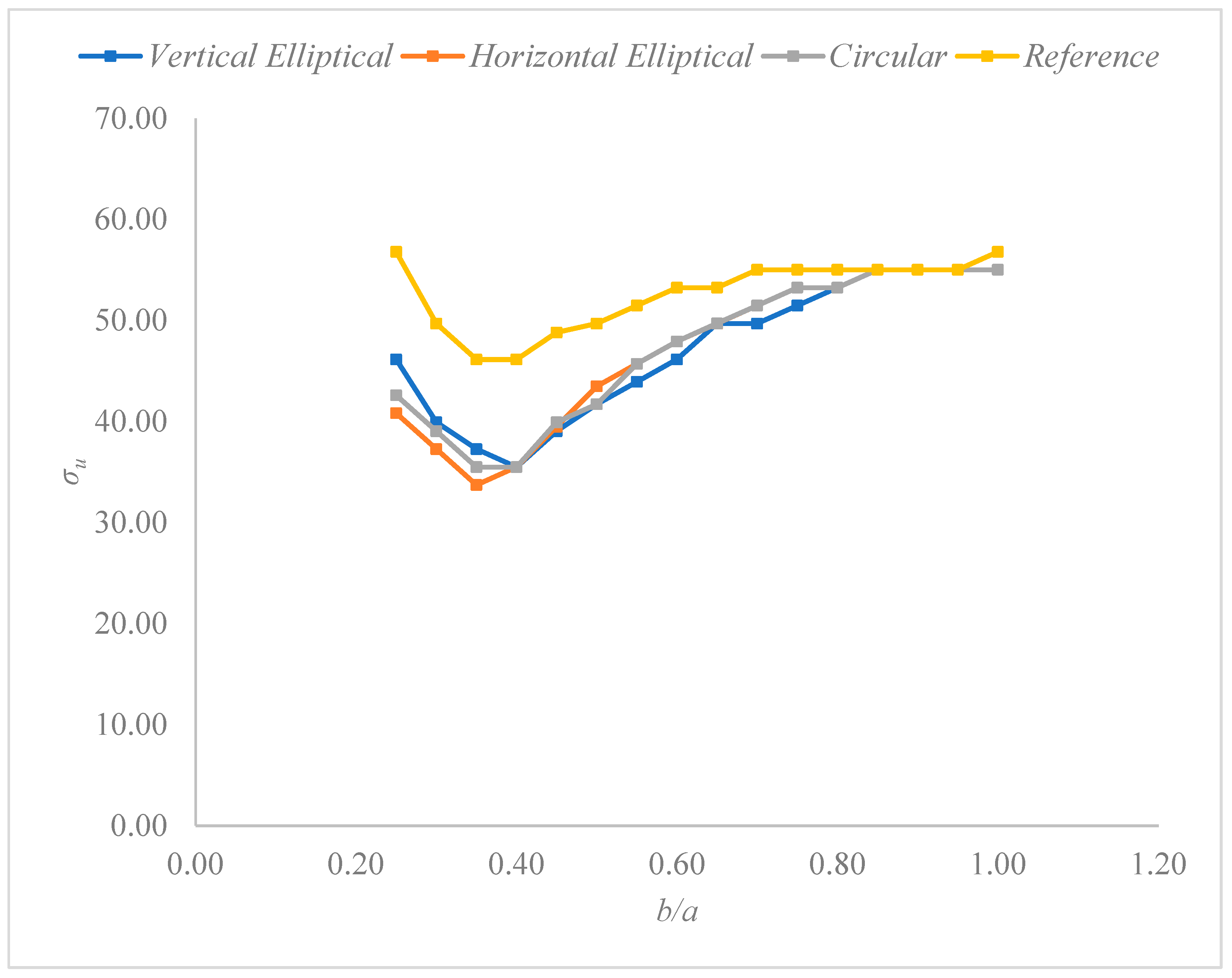
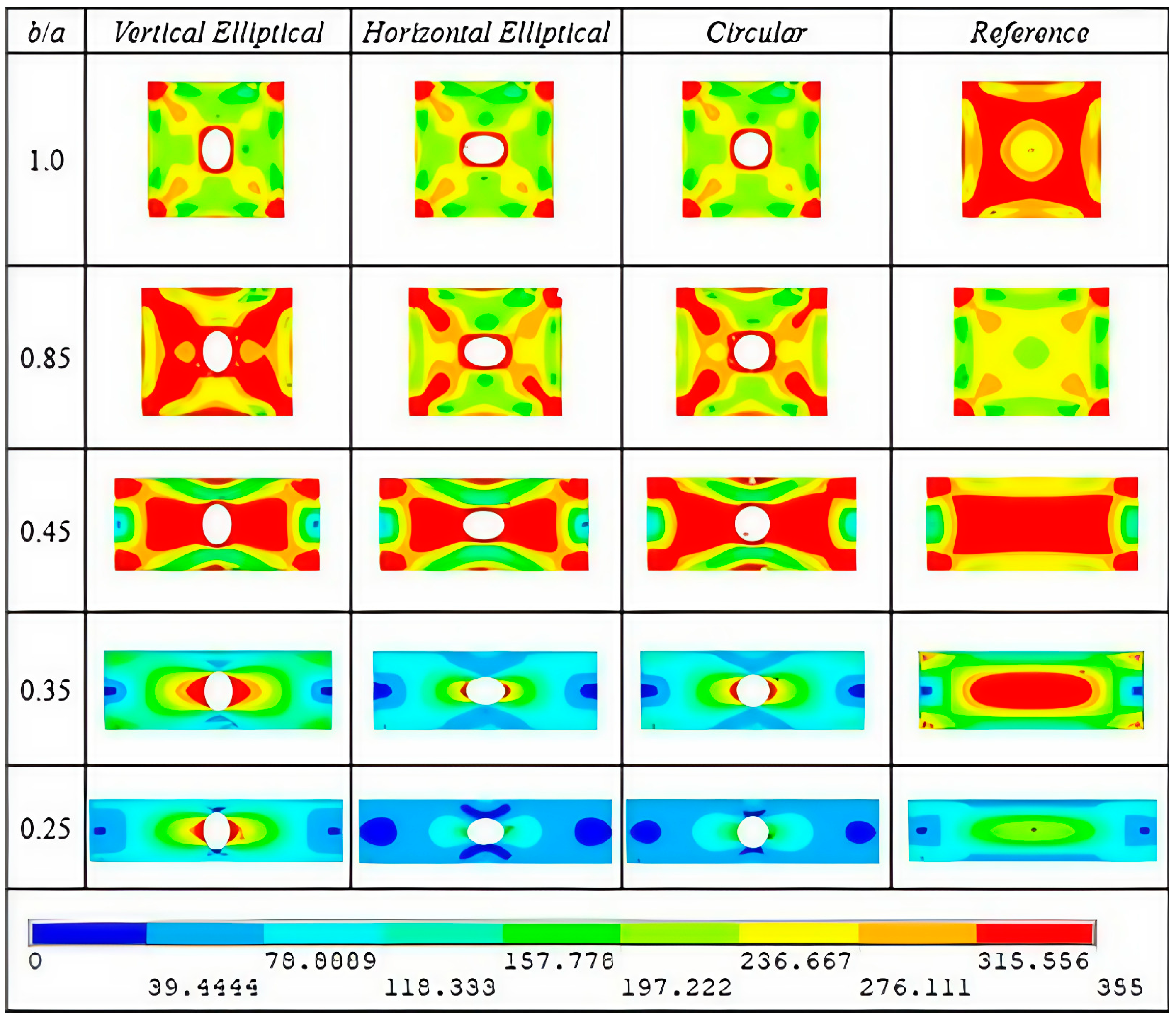
3.1. Ultimate Stress Analysis for AH-36 Steel

Simply supported plates made of AH-36 steel (see Table 1) were simulated using a FEM application, and the results of ultimate stresses corresponding to all analyzed b/a and perforation conditions are presented in Table A1 (see Appendix A). The obtained ultimate stresses are also shown in Figure 2, where four curves illustrate the mechanical behavior of the plates.
Based on the results presented in Table A1, it can be stated that, for most plate configurations, the presence of perforations compromises their mechanical behavior, reducing the ultimate stress. For b/a between 1.00 and 0.80, the geometry of perforation does not affect the ultimate stress obtained. For b/a between 0.75 and 0.45, it can be noted that the vertical elliptical geometry of perforation is the one that provides the worst mechanical behavior. Starting from a b/a = 0.40, where all ultimate stress values are the same for perforated plates, it is observed that, for b/a between 0.35 and 0.25, the vertical elliptical hole becomes the most favorable, as it exhibits the best mechanical behavior once its ultimate stress is higher than for circular or horizontal elliptical openings.
Regarding the curves presented in Figure 2, the mechanical behavior of the plates is illustrated by comparing the ultimate stresses obtained for each perforated plate and the reference plate. It is worth mentioning that, as expected, the reference plate (without a hole) consistently demonstrates the best mechanical behavior. This observation highlights the coherence among all the numerical results obtained. Among the perforated plates, it is evident that around a b/a = 0.40 the curves exhibit a noticeable change in behavior, with an increase in ultimate stress values. At this point, the vertical elliptical hole becomes the most favorable configuration of perforated plates, presenting the best mechanical behavior. Conversely, for intermediate b/a values (0.45 to 0.75), the vertical elliptical hole shows smaller ultimate stress values. Figure 3 illustrates von Mises stress distribution for five different b/a.
Based on results presented in Figure 3, the initial approach involves analyzing the von Mises stress distribution for the reference plates and comparing it with that obtained for the perforated plates. The manner in which the stress is distributed changes when a perforation is introduced, and different hole geometries also lead to distinct von Mises stress distributions. It is important to observe that the maximum stress distribution, due to the ultimate stress obtained by each plate, is concentrated around the perforation. Considering only the reference plates, for aspect ratios (b/a) 1.00 and 0.25, the ultimate stress is the same, equal to 56.80 MPa. On the other hand, if following the procedure proposed by the studies of [6,15], when plates provide the same mechanical behavior through the ultimate stress evaluation, the second point of analysis is the deflection. For these two plates, the b/a = 0.25 provides the best performance, with a deflection of 11.165 mm, while b/a = 1.00 presents 43.748 mm. Observing the distributions of stress in Figure 3, it is worth noting that, for the same ultimate stress, the plate with b/a = 0.25 exhibits a larger area under low stress values, while, for b/a = 1.00, most of the plate’s area is subjected to higher stress values. The same observation applies to other plates that reached the same ultimate stress values in this study. Considering the perforated plates, for b/a = 0.45, the best performance is for the circular hole (see Table A1 and Figure 2), once its ultimate stress is higher than that of the other perforations. In Figure 3 this result can be observed through the red areas distributed on the plate surface, being bigger than the red areas noted for elliptical holes and more symmetrical, as already observed in the study of [15]. On the other hand, for b/a = 0.25, the vertical elliptical hole exhibits the best performance, since its ultimate stress value is bigger than the other ones. For b/a smaller than 0.40 (see Figure 2), the best results are obtained for a vertical elliptical hole, and, also, the ultimate stress values increase as the b/a reduces. In Figure 3 it can be seen that for b/a = 0.25 the maximum values of von Mises stress are distributed around the perforation, showing the importance of the hole’s geometry in the mechanical behavior of the plate. For aspect ratios of 0.40 or smaller, the mechanical behavior changes considerably, if compared to higher values of b/a, concentrating the maximum von Mises stress distribution around the center of the plate. It can be observed in Figure 3 for all of the plates, including the reference plate (without a hole). For the perforated plates, these stress distributions are located around the hole, making the geometry of perforation important, which provides the best performance of the plate due to the best flow of maximum stresses. This characteristic can be understood through the CD method [71,72] based on the Constructal Principle of Optimal Distribution of Imperfections (PODI), the imperfections represented by the maximum stress concentrations [6,15,71,72]. As the aspect ratio b/a decreases, the horizontal dimension of the plate increases, while the vertical dimension decreases. Since the applied loading is a uniformly distributed load of equal magnitude, as the b/a decreases, the plate is subjected to significantly greater resultant forces in the vertical direction, while the resultant forces in the horizontal direction decrease. Consequently, for small values of the ratio b/a, the stress components acting in the y-direction tend to be larger and, therefore, more significant in terms of their distribution throughout the plate. According to the PODI, the best configuration for this plate is the one that allows for the most efficient flow of the most significant stresses (vertical stresses). In this case, the vertical elliptical hole becomes the most favorable option for b/a lower than 0.40, as its horizontal dimension is smaller than those of the other perforation types. Next, the x and y components of stresses, σx and σy, respectively, are considered to evaluate how the behavior of the components of stresses acts when varying the b/a of the plate.

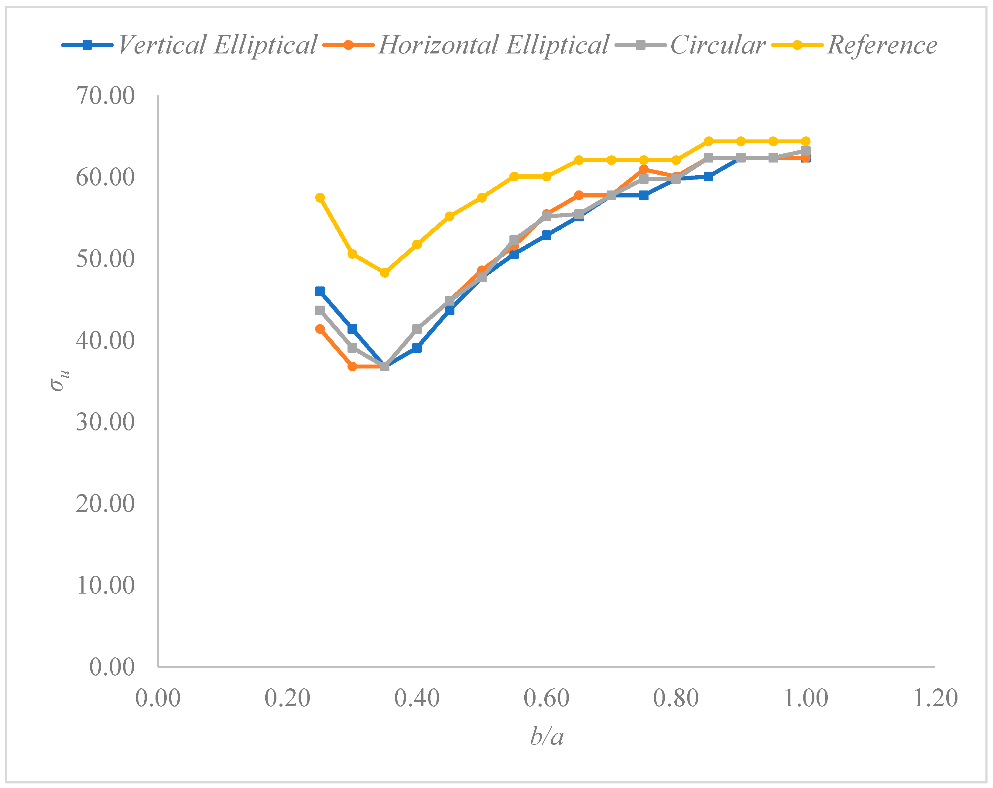
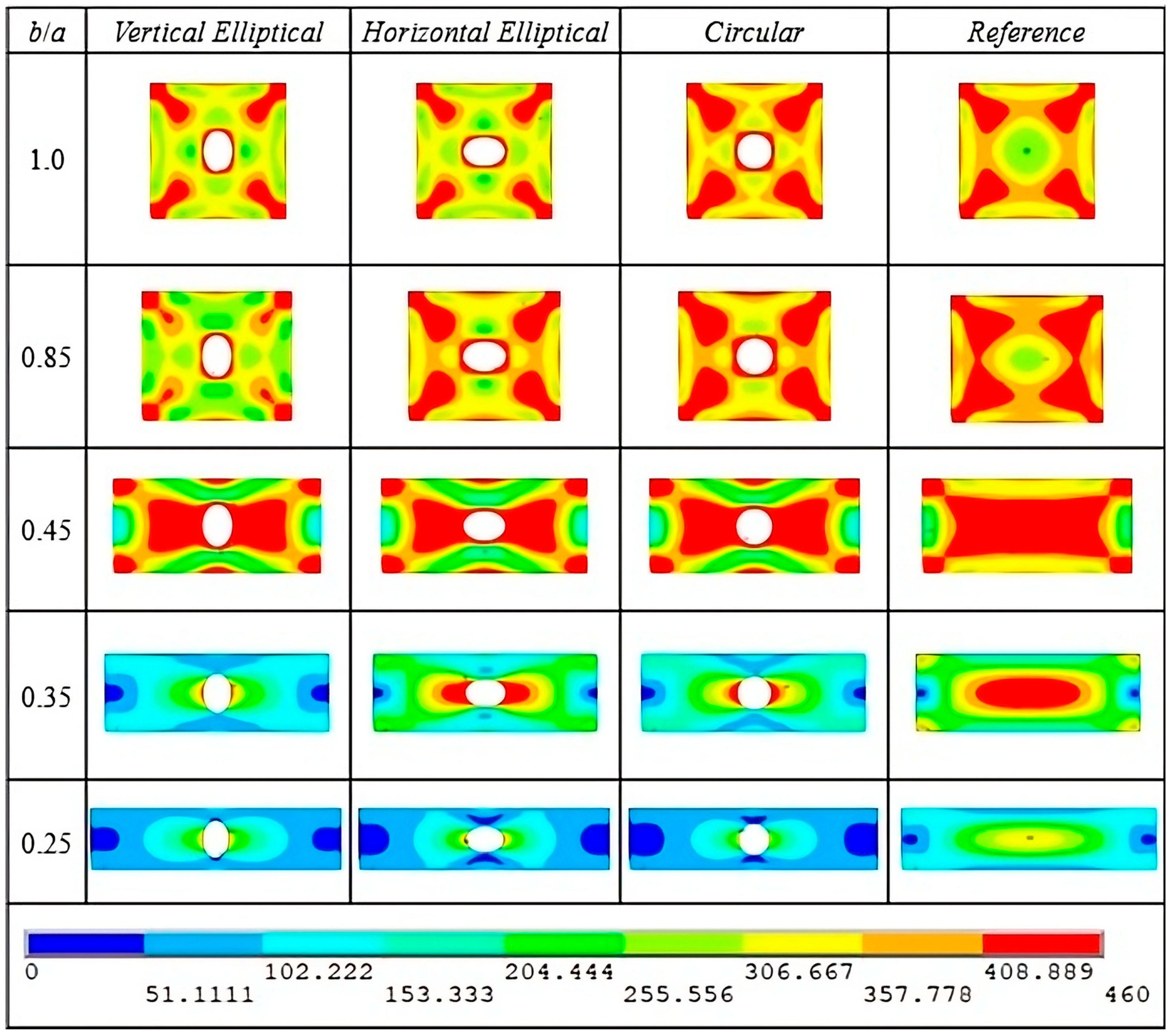
3.2. Ultimate Stress Analysis for AISI 4130 Steel

Understanding the importance of knowledge about elasto-plastic buckling behavior in different materials, plates made of AISI 4130 are tested, considering the increase in yield stress to 105 MPa when compared to AH-36 steel (see Table 1). Table A2 (see Appendix A) presents the obtained results for ultimate stress for each b/a, considering the reference plate and the perforated plates. Also, the results obtained are illustrated in Figure 4.
Considering the results presented in Table A2 and Figure 4, it is noted that most of the mechanical behaviors obtained follow the same characteristics observed for AH-36 steel. A few differences are noted due to the increase in yield stress (see Table 1), and the first of them is the increase in ultimate stress values obtained. For example, for the reference plates of b/a = 1.00, for AH-36 steel, the ultimate stress is 56.8 MPa, while for AISI 4130 it is 64.4 MPa, representing an increase of 13.38% in the ultimate stress for the material that has the yield stress approximately 30% higher. Once more, for the highest values of b/a, the ultimate stress is not affected by the hole geometry, except for b/a = 1.00 when the circular hole presents an ultimate stress 13.78% bigger than the other ones. From b/a = 0.85 until 0.40, the vertical elliptical hole is the worst one again, providing the smaller ultimate stress value for each b/a, except for b/a = 0.70 where all three ultimate stress values are the same; but, considering the deflection of the plate, the vertical elliptical hole provides the maximum z-displacement of 55.97 mm, while the horizontal elliptical and circular perforations obtained displacements of 48.15 mm and 50.65 mm, respectively. The change in mechanical behavior is noted for b/a = 0.35 when all ultimate stresses are the same, and for 0.30 and 0.25 the vertical elliptical hole proves to be the most favorable, as indicated by the ultimate stresses, which are higher than those obtained for the other two perforation types. Figure 5 illustrates the von Mises stress distributions obtained for analyzed plates.
Comparing Figure 3 and Figure 5, although the behavior is very similar to that of AH-36 steel, it is possible to observe that some distributions show larger red areas (indicating maximum stress regions) in the plates made of AISI 4130 steel. Unlike the previous material, when considering the reference plates, the plate with b/a = 1.00 shows superior performance compared to the plate having b/a = 0.25. Still regarding the reference plates, from b/a values of 1.00 to 0.85, the results indicate the same performance in terms of ultimate stress, although the plate with b/a = 1.00 exhibits lower deflection than the other plates. Similarly to the AH-36 analysis, as the plates increase their horizontal dimension, the von Mises maximum stresses become more concentrated around the hole, making the perforation geometry directly responsible for the mechanical behavior of the plate. Once the difference in the mechanical behavior for smaller values of b/a is observed, it is important to individually evaluate the plates and their behaviors as per the stress components σx and σy.

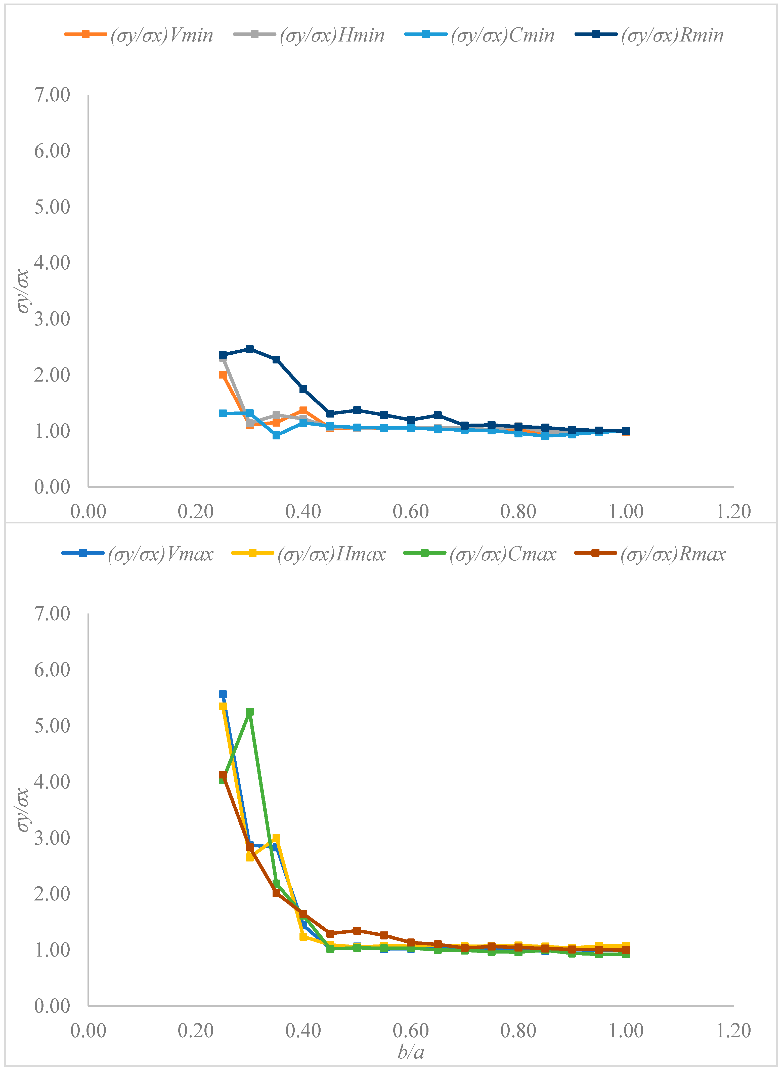
3.3. Stress Component Analysis Through the Ratio σyx

In the previous section, the influence of the plate’s aspect ratio (b/a) on the mechanical behavior of perforated plates was discussed, based on the analysis of ultimate stress and von Mises stress distributions. A change in mechanical behavior was observed as the plate length a increased, resulting in higher resultant forces in the y-direction. In order to further investigate what occurs in terms of stress components, x and y and to identify whether the increase in y-direction stresses is significant enough to define the plate’s mechanical behavior, a stress ratio σy/σx for each plate is presented below. As for the nomenclature, subscripts are used as follows: V for the vertical elliptical hole, H for the horizontal elliptical hole, C for the circular hole, and R for the reference plate. Additionally, the indicators min and max refer to compressive and tensile stresses, respectively. Table A3 (see Appendix A) and Figure 6 present the results obtained for each plate.
Considering Table A3, it is noted that the relation σy/σx keeps its values close to 1.00 for values from b/a = 1.00 until 0.45. In b/a = 0.40 an increase begins to appear in the relation σy/σx, which can be better illustrated by values obtained for b/a = 0.30 and b/a = 0.25, where values such as 5.57, 5.35, and 5.26 can be obtained for the vertical elliptical, horizontal elliptical, and circular holes, respectively. The increase in the relation σy/σx is more pronounced for tensile stress (max), while for compressive stress (min) the increase is smaller but happens too. For b/a = 0.25, comparing the tensile stress ratio, the vertical elliptical hole increases by 38.2% of the value of the ratio σy/σx in comparison with the circular hole.
In Figure 6 all plates are represented in curves for better observation of the variation in ratio σy/σx. The increase in obtained values is easily noted for tensile stress components (max) in aspect ratios b/a smaller than 0.40. Considering all four compressive stresses, only for the reference plate does the curve exhibit a bigger increase, reaching 2.46. For perforated plates, it is noted that a small increase can be observed for b/a = 0.25, but for most cases the compressive stress ratio remains around 1.00.
In order to compare both materials, and, if AISI 4130 presents mechanical behavior similar to AH-36, the same analysis is performed for the material that has a higher value of yield stress. Table A4 (see Appendix A) presents the obtained results for all plates simulated, and Figure 7 illustrates the obtained ratio values for the simulated plates.
Table A4 presents the obtained values for the σy/σx ratio, where a behavior similar to that observed in Table A3 can be identified. From b/a = 1.00 to 0.45, the results indicate that the stress components in the x and y directions are approximately equal, resulting in ratio values close to σy/σx = 1.00. Once again, a slight increase in the ratio values is observed at b/a = 0.40, followed by a significant increase for b/a smaller than 0.40.
In Figure 7 the increase in obtained values is easily noted for tensile stress components (max) in aspect ratios b/a smaller than 0.40. For this material, a difference is noted regarding compressive stresses, increasing its values too. For perforated plates, a big increase is noted for the vertical elliptical perforation in b/a = 0.25. Based on Table A2 and Figure 4, the vertical elliptical hole presents the best mechanical behavior compared to the other perforations. Comparing the obtained values for ratio σy/σx in b/a = 0.25 (see Table A4 and Figure 7), the influence of stress components on its mechanical behavior is evident once the vertical elliptical hole presents σy/σx = 6.10, which is 58.85% higher than that obtained for the horizontal elliptical hole and 26.82% higher than that for the circular hole. Once again, it is possible to draw the CD basis [71,72], which highlights the PODI as responsible for generating the best performance. As the x-dimension of the plate increases, the y-component of stress becomes greater than the x-component, making the y-direction the most significant for evaluating the stress flow. Considering that maximum stresses represent the system’s imperfections, it can be stated that, in these cases, the best performance will be achieved by the perforation geometry that causes the least interference in the stress flow along the y-direction. Taking Figure 5 as an example, for aspect ratios of 0.35 and 0.25, the concentration of higher stress values is limited to the center of the plate. Figure 7 illustrates the relevance of the y-component of stress in this behavior. Based on this, if the maximum stress occurs around the opening and the y-direction stress is the dominant component, then the perforation that enables the smoothest flow of stress along the y-axis is the one that promotes the best distribution of imperfections. In this case, the vertical elliptical perforation demonstrates the best performance due to its smaller dimension along the x-axis.

4. Conclusions

The elasto-plastic buckling of rectangular steel plates was analyzed, and their mechanical behaviors were determined through the ultimate stresses, deflections, and the ratio of stress components in the y and x directions. Two different steels were used for the simulation through the FEM, changing only the yield stress between them.
Although the materials differ in yield strength—with AISI 4130 presenting a value 29.58% higher than that of AH-36—the overall behavior of the obtained results is very similar. The main observation regarding the change in yield strength is that, for AISI 4130, the ultimate stresses are higher in each simulated test when compared to those of AH-36 steel. For b/a between 1.00 and 0.40 for AH-36, and between 1.00 and 0.35 for AISI 4130, the ultimate stress values gradually decrease as the b/a ratio decreases. Below these values, for smaller b/a, an inversion in behavior occurs, with the ultimate stress values increasing once again for each plate. Additionally, the vertical elliptical hole becomes the most favorable configuration for both materials, differing from the earlier trend where the circular or horizontal elliptical holes exhibited superior mechanical behavior.
The investigation of this change in mechanical behavior was carried out through the analysis of the σy/σx ratio, where the stress components in the x and y directions were evaluated as the b/a ratio varied. It was observed that this behavioral shift occurs similarly for both materials: at a b/a ratio of 0.40, the σy/σx ratio begins to show a slight increase, and, from 0.35 to 0.25, a considerable rise is observed, indicating that the stress components in the y-direction become significantly higher than those in the x-direction. As a result, the stresses in the y-direction become the most representative and decisive factors in determining the optimal perforation geometry for plates with smaller b/a.
This observation is consistent with the principles of Constructal Theory, which, in engineering problems, is applied through CD, where the optimal geometry satisfies the PODI. Considering the system’s imperfections as the maximum stresses and the flow system as the plates having a flow of stresses, it follows that, for smaller b/a, where y-direction stresses are predominant, the vertical elliptical hole performs best by facilitating the flow of vertical stresses in longer plates. In future works it is recommended to apply the methodology developed in the present to work to investigate the mechanical behavior of plates with different boundary conditions (such as clamped and free edges), loading conditions (such as lateral pressure), the quantity of perforations, materials (such as aluminum), and by using different finite elements (such as SOLSH190). Also, approaches considering the energy dissipation and the post-buckling collapse modes can strengthen the research about perforated plates under elasto-plastic buckling.

Author Contributions

Conceptualization, T.d.S. and L.A.I.; methodology, T.d.S., E.D.d.S. and L.A.I.; software, T.d.S. and E.A.C.; validation, T.d.S. and E.A.C.; formal analysis, T.d.S., E.D.d.S. and L.A.I.; investigation, T.d.S., E.A.C. and L.A.I.; resources, E.D.d.S. and L.A.I.; data curation, T.d.S. and E.A.C.; writing—original draft preparation, T.d.S. and L.A.I.; writing—review and editing, T.d.S., E.D.d.S. and L.A.I.; visualization, E.D.d.S. and L.A.I.; supervision, T.d.S. and L.A.I.; project administration, L.A.I.; funding acquisition, E.D.d.S. and L.A.I. All authors have read and agreed to the published version of the manuscript.

Funding

This research was funded by the National Council of Scientific and Technological Development (CNPq Processes: 308396/2021-9 and 309648/2021-1).

Data Availability Statement

The original contributions presented in this study are included in the article. Further inquiries can be directed to the corresponding author.

Conflicts of Interest

The authors declare no conflicts of interest.

Appendix A

Table A1. Ultimate stress obtained for plates of AH-36.
b/aVertical
Elliptical
(MPa)
Horizontal
Elliptical
(MPa)
Circular
(MPa)
Reference
(MPa)
1.0055.0355.0355.0356.80
0.9555.0355.0355.0355.03
0.9055.0355.0355.0355.03
0.8555.0355.0355.0355.03
0.8053.2553.2553.2555.03
0.7551.4853.2553.2555.03
0.7049.7051.4851.4855.03
0.6549.7049.7049.7253.25
0.6046.1547.9347.9353.25
0.5543.9345.7145.7151.48
0.5041.7143.4941.7149.70
0.4539.0539.4939.9448.81
0.4035.5035.5035.5046.15
0.3537.2833.7335.5046.15
0.3039.9437.2839.0549.70
0.2546.1540.8342.6056.80
Table A2. Ultimate stress obtained for plates of AISI 4130.
b/aVertical
Elliptical
(MPa)
Horizontal
Elliptical
(MPa)
Circular
(MPa)
Reference
(MPa)
1.0062.3962.3963.2564.40
0.9562.3962.3962.3964.40
0.9062.3962.3962.3964.40
0.8560.0962.3962.3964.40
0.8059.8060.0959.8062.10
0.7557.7960.9559.8062.10
0.7057.7957.7957.7962.10
0.6555.2057.7955.4962.10
0.6052.9055.4955.2060.09
0.5550.6051.6152.3360.09
0.5047.7348.5947.7357.50
0.4543.7044.8544.8555.20
0.4039.1041.4041.4051.75
0.3536.8036.8036.8048.30
0.3041.4036.8039.1050.60
0.2546.0041.4043.7057.50
Table A3. Stress components ratio for AH-36.
b/a(σy/σx)Vmin(σy/σx)Vmax(σy/σx)Hmin(σy/σx)Hmax(σy/σx)Cmin(σy/σx)Cmax(σy/σx)Rmin(σy/σx)Rmax
1.000.991.011.001.070.990.931.001.00
0.951.000.990.991.070.980.931.011.01
0.900.981.010.981.040.940.941.021.01
0.850.940.980.981.060.911.001.061.03
0.801.021.011.091.080.960.961.081.05
0.751.021.031.021.071.010.971.111.06
0.701.031.031.061.071.020.991.101.04
0.651.051.051.051.091.031.001.281.10
0.601.061.021.061.071.051.041.201.13
0.551.051.021.061.071.061.031.291.26
0.501.061.071.051.051.061.041.371.35
0.451.051.031.071.091.091.021.311.30
0.401.371.441.221.241.151.621.741.65
0.351.152.831.283.000.922.192.282.02
0.301.102.871.142.651.325.262.462.84
0.252.015.572.315.351.314.032.364.13
Table A4. Stress components ratio for AISI 4130.
b/a(σy/σx)Vmin(σy/σx)Vmax(σy/σx)Hmin(σy/σx)Hmax(σy/σx)Cmin(σy/σx)Cmax(σy/σx)Rmin(σy/σx)Rmax
1.001.000.991.011.011.001.001.001.00
0.950.980.991.011.001.001.001.001.00
0.900.961.000.990.990.970.991.011.00
0.850.960.850.971.000.951.001.021.00
0.800.950.951.071.051.020.971.041.04
0.751.010.910.970.990.991.001.071.06
0.701.030.991.071.041.011.021.091.05
0.651.040.981.061.021.021.031.091.00
0.601.061.011.071.031.041.001.231.14
0.551.061.001.071.071.061.021.071.01
0.501.071.021.071.081.081.051.211.22
0.451.081.011.071.101.081.041.281.30
0.401.381.131.081.081.091.051.501.49
0.353.063.302.041.832.612.282.622.04
0.302.272.513.063.663.213.962.752.74
0.252.656.102.623.843.024.812.573.41

References

  1. Jones, R.M. Buckling of Bars, Plates and Shells; Bull Ridge Publishing: Blacksburg, VA, USA, 2006. [Google Scholar]
  2. Chajes, A. Principles of Structural Theory; Prentice-Hall: Englewood Cliffs, NJ, USA, 1974. [Google Scholar]
  3. Szilard, R. Theories and Applications of Plate Analysis: Classical Numerical and Engineering Methods; John Wiley & Sons: Hoboken, NJ, USA, 2004. [Google Scholar]
  4. Åkesson, B. Plate Buckling in Bridges and Other Structures; Taylor & Francis Group: London, UK, 2007. [Google Scholar]
  5. Shojaee, T.; Mohammadi, B.; Madoliat, R.; Salimi-Majd, D. Development of a finite strip method for efficient prediction of buckling and post-buckling in composite laminates containing a cutout with/without stiffener. Compos. Struct. 2019, 210, 538–552. [Google Scholar] [CrossRef]
  6. Da Silveira, T.; Fragasssa, C.; Rocha, L.A.O.; Dos Santos, E.D.; Isoldi, L.A. Geometric Investigation of Thin Perforated Steel Plates Under Biaxial Elasto-Plastic Buckling by using Constructal Design. Rep. Mech. Eng. 2024, 5, 43–67. [Google Scholar]
  7. Asemi, K.; Ashrafi, H.; Shariyat, M. Three-dimensional stress and free vibration analyses of functionally graded plates with circular holes by the use of the graded finite element method. J. Appl. Mech. Tech. Phys. 2016, 57, 690–700. [Google Scholar] [CrossRef]
  8. Liang, K.; Yin, Z. Investigation on nonlinear buckling performance of the optimized wing structure under the realistic flight cases. Aerosp. Sci. Technol. 2023, 139, 108416. [Google Scholar] [CrossRef]
  9. Cao, Y.; Zhou, Y.; Tian, S.; Takagi, J.; Li, Z.; Fang, D.; Fang, X. Performance of novel perforated double-core steel-plate assembled buckling-restrained braces. J. Build. Eng. 2024, 82, 108326. [Google Scholar] [CrossRef]
  10. Figueiredo, J.; Simões, F.; da Costa, A.P. Unilateral buckling of thin plates by complementarity eigenvalue analyses. Thin-Walled Struct. 2024, 205, 112387. [Google Scholar] [CrossRef]
  11. Ghorbanhosseini, S.; Yaghoubi, S.; Bahrambeigi, M.R. A Comprehensive Study on the Effects of the Boundary Conditions on the Elastic Buckling Capacity of a Perforated Plate. Int. J. Adv. Des. Manuf. Technol. 2021, 14, 45–53. [Google Scholar] [CrossRef]
  12. Gore, R.; Lokavarapu, B.R. Effect of Elliptical Cutout on Buckling Load for Isotropic Thin Plate. In Innovations in Mechanical Engineering: Select Proceedings of ICIME 2021; Springer: Singapore, 2022. [Google Scholar] [CrossRef]
  13. Rocha, L.A.; Lorente, S.; Bejan, A. Constructal theory in heat transfer. In Handbook of Thermal Science and Engineering; Springer: Cham, Switzerland, 2018; pp. 329–360. [Google Scholar] [CrossRef]
  14. dos Santos, E.D.; Isoldi, L.A.; Gomes, M.d.N.; Rocha, L.A. The constructal design applied to renewable energy systems. In Sustainable Energy Technologies; CRC Press: Boca Raton, FL, USA, 2017; pp. 45–62. [Google Scholar] [CrossRef]
  15. Da Silveira, T.; Pinto, V.T.; Neufeld, J.P.S.; Pavlovic, A.; Rocha, L.A.O.; Dos Santos, E.D.; Isoldi, L.A. Applicability evidence of constructal design in structural engineering: Case study of biaxial elasto-plastic buckling of square steel plates with elliptical cutout. J. Appl. Comput. Mech. 2021, 7, 922–934. [Google Scholar]
  16. Trahair, N.S.; Bradford, M.; Nethercot, D.; Gardner, L. The Behavior and Design of Steel Structures to EC3; CRC Press: Boca Raton, FL, USA, 2017. [Google Scholar] [CrossRef]
  17. Saad-Eldeen, S.; Garbatov, Y. Experimental and Numerical Analysis of Structural Capacity of Perforated Stiffened Plates. J. Mar. Sci. Eng. 2023, 11, 842. [Google Scholar] [CrossRef]
  18. Dong, J.; Ma, X.; Zhuge, Y.; Mills, J.E. Local buckling of thin plate on tensionless elastic foundations under interactive uniaxial compression and shear. Theor. Appl. Mech. Lett. 2018, 8, 75–82. [Google Scholar] [CrossRef]
  19. Baumgardt, G.R.; Fragassa, C.; Rocha, L.A.O.; Dos Santos, E.D.; Da Silveira, T.; Isoldi, L.A. Computational model verification and validation of elastoplastic buckling due to combined loads of thin plates. Metals 2023, 13, 731. [Google Scholar] [CrossRef]
  20. Milazzo, A.; Benedetti, I.; Gulizzi, V. An extended Ritz formulation for buckling and post-buckling analysis of cracked multilayered plates. Compos. Struct. 2018, 201, 980–994. [Google Scholar] [CrossRef]
  21. Malikan, M.; Nguyen, V.B. A novel one-variable first-order shear deformation theory for biaxial buckling of a size-dependent plate based on Eringen’s nonlocal differential law. World J. Eng. 2018, 15, 633–645. [Google Scholar] [CrossRef]
  22. da Silveira, T.; Baumgardt, G.; Rocha, L.; dos Santos, E.; Isoldi, L. Numerical simulation and constructal design applied to biaxial elastic buckling of plates of composite material used in naval structures. Compos. Struct. 2022, 290, 115503. [Google Scholar] [CrossRef]
  23. Farajpour, M.; Shahidi, A.; Farajpour, A. A nonlocal continuum model for the biaxial buckling analysis of composite nanoplates with shape memory alloy nanowires. Mater. Res. Express 2018, 5, 035026. [Google Scholar] [CrossRef]
  24. Kaveh, A.; Dadras, A.; Malek, N.G. Optimum stacking sequence design of composite laminates for maximum buckling load capacity using parameter-less optimization algorithms. Eng. Comput. 2019, 35, 813–832. [Google Scholar] [CrossRef]
  25. Kaveh, A.; Dadras, A.; Malek, N.G. Buckling load of laminated composite plates using three variants of the biogeography-based optimization algorithm. Acta Mech. 2018, 229, 1551–1566. [Google Scholar] [CrossRef]
  26. Moita, J.S.; Araújo, A.L.; Correia, V.F.; Soares, C.M.M.; Herskovits, J. Material distribution and sizing optimization of functionally graded plate-shell structures. Compos. Part B Eng. 2018, 142, 263–272. [Google Scholar] [CrossRef]
  27. Ehsani, A.; Dalir, H. Multi-objective optimization of composite angle grid plates for maximum buckling load and minimum weight using genetic algorithms and neural networks. Compos. Struct. 2019, 229, 111450. [Google Scholar] [CrossRef]
  28. da Silva, C.C.C.; Helbig, D.; Cunha, M.L.; dos Santos, E.D.; Rocha, L.A.O.; Real, M.d.V.; Isoldi, L.A. Numerical buckling analysis of thin steel plates with centered hexagonal perforation through constructal design method. J. Braz. Soc. Mech. Sci. Eng. 2019, 41, 309. [Google Scholar] [CrossRef]
  29. Hu, H.-S.; Fang, P.-P.; Liu, Y.; Guo, Z.-X.; Shahrooz, B.M. Local buckling of steel plates in composite members with tie bars under axial compression. Eng. Struct. 2020, 205, 110097. [Google Scholar] [CrossRef]
  30. Zureick, A.-H. On the buckling of an isotropic rectangular plate uniformly compressed on two simply supported edges and with two free unloaded edges. Thin-Walled Struct. 2018, 124, 180–183. [Google Scholar] [CrossRef]
  31. Lima, J.P.S.; Cunha, M.L.; dos Santos, E.D.; Rocha, L.A.O.; de Vasconcellos Real, M.; Isoldi, L.A. Constructal Design for the ultimate buckling stress improvement of stiffened plates submitted to uniaxial compressive load. Eng. Struct. 2020, 203, 109883. [Google Scholar] [CrossRef]
  32. Yuan, T.; Yang, Y.; Kong, X.; Wu, W. Similarity criteria for the buckling process of stiffened plates subjected to compressive load. Thin-Walled Struct. 2021, 158, 107183. [Google Scholar] [CrossRef]
  33. Falkowicz, K.; Debski, H. Stability analysis of thin-walled composite plate in unsymmetrical configuration subjected to axial load. Thin-Walled Struct. 2021, 158, 107203. [Google Scholar] [CrossRef]
  34. Hou, J.; Guo, L.; Yan, J. Steel plate–restraining panel interaction behavior in buckling-restrained steel plate shear walls. Thin-Walled Struct. 2021, 169, 108348. [Google Scholar] [CrossRef]
  35. Zhang, Q.; Sun, Y. Statics, vibration, and buckling of sandwich plates with metamaterial cores characterized by negative thermal expansion and negative Poisson’s ratio. Appl. Math. Mech. 2023, 44, 1457–1486. [Google Scholar] [CrossRef]
  36. Jin, Q.; Leng, L.; Yang, S. Buckling analysis of composite plates surface bonded with graphene-reinforced piezoelectric actuators. Polym. Compos. 2024, 45, 1793–1809. [Google Scholar] [CrossRef]
  37. Park, J.-S.; Yi, M.-S. Root Causes of Thin-Plate Buckling Damage at the Aft-End in Crude Oil Tanker and Verification through Buckling Analysis. Metals 2024, 14, 158. [Google Scholar] [CrossRef]
  38. Cheng, B.; Zhao, J. Strengthening of perforated plates under uniaxial compression: Buckling analysis. Thin-Walled Struct. 2010, 48, 905–914. [Google Scholar] [CrossRef]
  39. Mohammadzadeh, B.; Choi, E.; Kim, W.J. Comprehensive investigation of buckling behavior of plates considering effects of holes. Struct. Eng. Mech. 2018, 68, 261–275. [Google Scholar] [CrossRef]
  40. El-Sawy, K.M.; Martini, M.I. Stability of biaxially loaded square plates with single central holes. Ships Offshore Struct. 2010, 5, 283–293. [Google Scholar] [CrossRef]
  41. Wysmulski, P. Analysis of the Effect of an Open Hole on the Buckling of a Compressed Composite Plate. Materials 2024, 17, 1081. [Google Scholar] [CrossRef] [PubMed]
  42. Deng, C.; Qi, X.; Liu, Y. Numerical study on equilibrium stability of objects in fluid flow—A case study on constructal law. Case Stud. Therm. Eng. 2019, 15, 100539. [Google Scholar] [CrossRef]
  43. Vaghefi, R. Elastoplastic buckling analysis of FG skew plates using a 3D meshfree Tchebychev-radial point interpolation approach. Eng. Struct. 2024, 311, 118162. [Google Scholar] [CrossRef]
  44. Vaghefi, R. Three-dimensional elastoplastic post-buckling analysis of functionally graded plates using a novel meshfree Tchebychev-radial point interpolation approach. Mech. Based Des. Struct. Mach. 2024, 53, 1120–1143. [Google Scholar] [CrossRef]
  45. Amor, M.B.H.; Bettaieb, M.B.; Mezlini, S.; Abed-Meraim, F. Development and implementation of a new computational strategy for the prediction of elastoplastic buckling. Int. J. Appl. Mech. 2024, 16, 2450091. [Google Scholar]
  46. Shanmugam, N.; Narayanan, R. Ultimate Strength of Biaxially Loaded Plates. In Stability and Ductility of Steel Structures (SDSS’97); Elsevier: Amsterdam, The Netherlands, 1998. [Google Scholar] [CrossRef]
  47. Pavlovic, A.; Fragassa, C.; Minak, G. Analiza izvijanja teleskopske dizalice: Teorijska i numerička procjena kliznih oslonaca. Teh. Vjesn. 2017, 24, 729–735. [Google Scholar] [CrossRef]
  48. Fragassa, C.; Minak, G.; Pavlovic, A. Measuring deformations in the telescopic boom under static and dynamic load conditions. Facta Univ. Ser. Mech. Eng. 2020, 18, 315–328. [Google Scholar] [CrossRef]
  49. ANSYS. Mechanical APDL 2024R2; ANSYS Inc.: Canonsburg, PA, USA, 2024. [Google Scholar]
  50. Ota, N.S.N. O Elemento Finito T6-3i na Análise de Placas e Dinâmica de Cascas. Master’s Thesis, Escola Politécnica da Universidade de São Paulo, São Paulo, Brazil, 2016. [Google Scholar]
  51. Vieira, R.L.; Baumgardt, G.R.; Dos Santos, E.D.; Rocha, L.A.O.; Da Silveira, T.; Lima, J.P.S.; Isoldi, L.A. Computational Model and Constructal Design Applied to Thin Stiffened Plates Subjected to Elastoplastic Buckling Due to Combined Loading Conditions. Appl. Sci. 2025, 15, 3354. [Google Scholar] [CrossRef]
  52. Musmar, M.A. A Parametric Study on the Buckling Behavior of Square Steel Plates under Uniaxial Compression. Civ. Eng. Arch. 2021, 9, 2292–2302. [Google Scholar] [CrossRef]
  53. Han, H.; Dong, C. Buckling Analysis for Carbon and Glass Fiber Reinforced Hybrid Composite Stiffened Panels. J. Compos. Sci. 2024, 8, 34. [Google Scholar] [CrossRef]
  54. Pavlovic, A.; Fragassa, C. Geometry optimization by fem simulation of the automatic changing gear. Rep. Mech. Eng. 2020, 1, 199–205. [Google Scholar] [CrossRef]
  55. Skripnyak, V.A.; Iokhim, K.; Skripnyak, E.; Skripnyak, V.V. Modeling of titanium alloys plastic flow in linear friction welding. Facta Univ. Ser. Mech. Eng. 2021, 19, 91–104. [Google Scholar] [CrossRef]
  56. Bhadra, R.; Jana, T.; Mitra, A.; Sahoo, P. Effect of CNT radius on flattening contact behaviour of CNT-Al nanocomposite: A numerical approch. Rep. Mech. Eng. 2023, 4, 121–130. [Google Scholar] [CrossRef]
  57. El-Sawy, K.M.; Nazmy, A.S.; Martini, M.I. Elasto-plastic buckling of perforated plates under uniaxial compression. Thin-Walled Struct. 2004, 42, 1083–1101. [Google Scholar] [CrossRef]
  58. Shanmugam, N.; Thevendran, V.; Tan, Y. Design formula for axially compressed perforated plates. Thin-Walled Struct. 1999, 34, 1–20. [Google Scholar] [CrossRef]
  59. Narayanan, R.; Chow, F.-Y. Strength of Biaxially Compressed Perforated Plates. 1984. Available online: https://scholarsmine.mst.edu/cgi/viewcontent.cgi?article=1168&context=isccss (accessed on 15 January 2025).
  60. Bejan, A.; Peder Zane, J. Design in nature. Mech. Eng. 2012, 134, 42–47. [Google Scholar] [CrossRef]
  61. Rocha, L.; Santos, E.D.; Cunha, D.; Garcia, F.; Lorenzini, G.; Biserni, C.; Letzow, M.; Costa, J.; Souza, J.; Isoldi, L. Constructal Design of Thermal Systems. In Constructal Law and the Unifying Principle of Design; Springer: New York, NY, USA, 2013; pp. 295–321. [Google Scholar] [CrossRef]
  62. Bejan, A. Constructal theory of pattern formation. Hydrol. Earth Syst. Sci. 2007, 11, 753–768. [Google Scholar] [CrossRef]
  63. Chen, L.; Feng, H.; Zhang, F.; Ge, Y. Constructal design for composite heat dissipating structure composed of an “arrow”-shaped high conductivity channel and an externally connected “T”-shaped fin. Int. Commun. Heat Mass Transf. 2024, 153, 107341. [Google Scholar] [CrossRef]
  64. Cunegatto, E.H.T.; Gotardo, M.; Zinani, F.S.F. Numerical analysis of tube arrangements with one, two, and four degrees of freedom for heat transfer with pseudoplastic fluids. Int. J. Heat Mass Transf. 2023, 208, 124080. [Google Scholar] [CrossRef]
  65. Dan, Z.; Feng, H.; Chen, L.; Liao, N.; Ge, Y. Constructal design of printed circuit recuperator for S-CO2 cycle via multi-objective optimization algorithm. Sci. China Technol. Sci. 2024, 67, 285–294. [Google Scholar] [CrossRef]
  66. Feijó, B.C.; Pavlovic, A.; Rocha, L.A.O.; Isoldi, L.A.; Lorente, S.; dos Santos, E.D. Geometrical investigation of microchannel with two trapezoidal blocks subjected to laminar convective flows with and without boiling. Rep. Mech. Eng. 2022, 3, 20–36. [Google Scholar] [CrossRef]
  67. Feng, H.; Sun, K.; Chen, L.; Ge, Y. Constructal design of a nanofluid cooling channel with sidewall ribs and cavities in a rectangular heat generation body. Case Stud. Therm. Eng. 2023, 41, 102640. [Google Scholar] [CrossRef]
  68. Feng, H.; Zhang, Z.; Chen, L.; Ge, Y. Constructal design for H-shaped compound heat transfer path in a rectangular heat generation body. Int. J. Heat Mass Transf. 2024, 225, 125442. [Google Scholar] [CrossRef]
  69. Liu, H.; Xi, K.; Xie, Z.; Lu, Z.; Chen, H.; Zhang, J.; Ge, Y. Constructal design of double-layer asymmetric flower baffles. Energy 2023, 280, 128254. [Google Scholar] [CrossRef]
  70. Lu, Z.; Xie, Z.; Xi, K.; Lin, D.; Liu, H.; Ge, Y.; Wu, F. Constructal evolutionary design of liquid cooling heat sink embedded in 3D-IC based on deep neural network prediction. Int. Commun. Heat Mass Transf. 2024, 152, 107273. [Google Scholar] [CrossRef]
  71. Bejan, A.; Lorente, S. Design with Constructal Theory; Wiley: Hoboken, NJ, USA, 2008. [Google Scholar]
  72. Bejan, A.; Lorente, S. The constructal law of design and evolution in nature. Philos. Trans. R. Soc. B Biol. Sci. 2010, 365, 1335–1347. [Google Scholar] [CrossRef]
  73. Troina, G.; Cunha, M.; Pinto, V.; Rocha, L.; dos Santos, E.; Fragassa, C.; Isoldi, L. Computational Modeling and Constructal Design Theory Applied to the Geometric Optimization of Thin Steel Plates with Stiffeners Subjected to Uniform Transverse Load. Metals 2020, 10, 220. [Google Scholar] [CrossRef]
  74. Cunha, M.L.; Troina, G.S.; Santos, E.D.; Rocha, L.A.O.; Isoldi, L.A. Computational modeling and Constructal Design method applied to the geometric optimization of stiffened steel plates subjected to uniform transverse load. Res. Eng. Struct. Mat. 2018, 4, 139–149. [Google Scholar] [CrossRef]
  75. Callister, W.D. Materials Science and Engineering: An Introduction, 6th ed.; John Wiley & Sons: New York, NY, USA, 2002. [Google Scholar]
  76. Callister, W.D.; Rethwisch, D.G. Materials Science and Engineering: An Introduction, 9th ed.; John Wiley & Sons: Hoboken, NJ, USA, 2016. [Google Scholar]
  77. Adak, M.; Soares, C.G. Effects of different restraints on the weld induced residual deformations and stresses in a steel plate. Int. J. Adv. Manuf. Technol. 2014, 71, 699–710. [Google Scholar] [CrossRef]
  78. ASTM A131/A131M–19; Standard Specification for Structural Steel for Ships. ASTM International: West Conshohocken, PA, USA, 2019.
  79. Purnama, D.; Winarto, W.; Sofyan, N.; Prihastomo, A.; Ito, K. Microstructure and Mechanical Properties of Ah-36 Steel Weldment Welded using Magnesium Modified E6013 Electrode. Int. J. Technol. 2020, 11, 48–59. [Google Scholar] [CrossRef]
Figure 1. Computational domain of the studied plates: (a) Reference plate. (b) Perforated plate.
Metals 15 00786 g001
Figure 2. Ultimate stresses obtained for AH-36 plates.
Metals 15 00786 g002
Figure 3. Distributions of von Mises stresses for the AH-36 plates.
Metals 15 00786 g003
Figure 4. Ultimate stresses obtained for AISI 4130 plates.
Metals 15 00786 g004
Figure 5. Distributions of von Mises stresses for the AISI 4130 plates.
Metals 15 00786 g005
Figure 6. Stress components ratio for AH-36.
Metals 15 00786 g006
Figure 7. Stress components ratio for AISI 4130.
Metals 15 00786 g007
Table 1. Material properties of the materials used in this case study.
SteelE (GPa)νσy (MPa)
AH-362100.3355
AISI 41302100.3460
Table 2. Dimensions of the plates for each aspect ratio.
b/aa (mm)b (mm)
1.001414.2141414.214
0.951450.9531378.405
0.901490.7121341.641
0.851533.9301303.840
0.801581.1391264.911
0.751632.9931224.745
0.701690.3091183.216
0.651754.1161140.175
0.601825.7421095.445
0.551906.9251048.809
0.502000.0001000.000
0.452108.185948.683
0.402236.068894.427
0.352390.457836.660
0.302581.989774.597
0.252828.427707.107
Table 3. Dimensions of perforations used in this case study.
Perforationb0/a0b0 (mm)a0 (mm)
Circular1.000356.830356.830
Horizontal Elliptical0.707300.000424.426
Vertical Elliptical1.415424.426300.000
Disclaimer/Publisher’s Note: The statements, opinions and data contained in all publications are solely those of the individual author(s) and contributor(s) and not of MDPI and/or the editor(s). MDPI and/or the editor(s) disclaim responsibility for any injury to people or property resulting from any ideas, methods, instructions or products referred to in the content.

