Abstract
This study aimed to investigate the effect of the fatigue life enhancement of the rib-to-deck welded joints of orthotropic steel decks (OSDs) by extended peening treatment utilization. First, hammer peening was conducted around the weld bead of the test specimens of OSDs. It was found that the treatment on both the weld toes of the deck and the U-rib plates caused a deformation of the U-rib plate, i.e., peen forming. Then, fatigue tests were performed under R = 0.0, using an out-of-plane bending fatigue test machine by applying several magnitudes of pre-loadings, and the results showed that the specimens with peen forming had one JSSC class higher than the deck plate only. Finally, numerical simulations of peening treatment and peen forming were performed to reveal the reason for higher fatigue life enhancement by peen forming. Simulation results showed that peen forming would introduce about three times higher compressive residual stress at the weld root of the deck plate side than the peening treatment on the deck plate only, and induced compressive residual stresses around the weld root by peen forming were kept even after applying the pre-loadings. Therefore, it can be concluded that peen forming, as an extended peening treatment utilization, is highly effective in enhancing the fatigue life of OSDs.
1. Introduction
Orthotropic steel decks (OSDs) have been widely used in many long-span bridges and urban highways because of their light-weight, high strength, and durability characteristics and rapid construction [1]. OSDs are mainly assembled from comparatively thin steel plates (6–16 mm thickness) with welded joints. The assembled thin steel plates are stiffened longitudinally by ribs. These ribs provide additional stiffness to an OSD and help distribute the wheel loads [2,3,4]. Based on rib connection, the rib is generally classified as open- and/or closed-rib. Among them, many fatigue cracks forming the welded joints in the closed rib have been reported [5,6,7,8]. Figure 1 shows the typical welded joints in OSDs [9]. The fatigue cracks initiated from the rib-to-deck welded joints of OSDs are often considered troublesome, especially in Japan [6]. The fatigue cracks initiate from its weld root and propagate toward the weld bead and/or the deck plate [9]. These crack initiations cannot be visible. When these cracks become visible in the weld bead, they will be huge. In this condition, there is a possibility that the stiffness of the longitudinal rib suddenly decreases, involving the OSD in a critical situation, such as failure, collapse, and so on [10]. Therefore, the fatigue life of the weld root needs to be enhanced to prevent crack initiation from there and enhance its fatigue life.
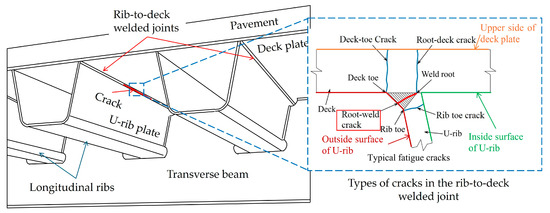
Figure 1.
Typical rib-to-deck welded joint in an OSD and the reported cracks in it.
One of the common methods to improve the fatigue strength of the welded joints in steel bridges is the peening technique. The peening technique is classified as a residual stress modification method, e.g., needle peening, hammer peening, and shot peening [11,12,13,14]. Peening treatment strikes the weld toe by using a metal pin and/or hammer vibrated by compressed air [11]. The pin striking proactively causes severe plastic flow around the peened weld and introduces beneficial compressive residual stresses against fatigue there [12,13,14]. Some researchers have utilized peening treatment for fatigue life extension of the weld root in OSDs [15,16]. Matsumoto et al. [15] conducted hammer peening with the ICR apparatus (HPICR apparatus) on the deck plate from its outside and both outside and inside of the U-rib and demonstrated that the HPICR apparatus from the inside of the U-rib or the upside of the deck plate effectively improved the fatigue strength against the root-deck crack. Tsutsumi et al. [16] experimentally and numerically investigated the effect of the HPICR apparatus on the weld root and revealed that the HPICR apparatus from the inside or both inside and outside of the U-rib can effectively introduce compressive residual stress and considerably improve the fatigue strength of the root-deck crack. Therefore, peening treatment has the potential to enhance the fatigue life of the weld root by introducing compressive residual stress and is effective in preventing root-deck cracks in OSDs.
On the other hand, one might expect a longer fatigue life to be achieved when compressive residual stress is introduced more directly into the weld root of OSDs. Some researchers have attempted to introduce compressive residual stress directly into the weld root of OSDs [17,18]. Shimanuki et al. [17] tried to apply pre-overload using an oil jack from inside the U-rib, causing tensile yielding around the weld root and introducing compressive stress upon release of the pre-overload. They demonstrated through experiments that fatigue life could be several times longer by the application of pre-overload. Tsutsumi et al. [18] clarified the mechanism of fatigue life enhancement of the weld root by the application of a pre-overload by means of FE analysis. Their idea was an approach from the inside of the U-rib, which might be challenging in application to the existing OSDs. Hence, making the approach possible from the outside is a very useful option when considering its application for existing OSDs. Herein, as the U-rib basically consists of comparatively thin steel, around 6 mm, one possibility would be peen forming. Peen forming is a cold working process that forms the metal sheet into a complex shape by using shot media [19], metal balls [20], or lasers [21], and, for example, has already been used to make components like wind skin for airplanes [19]. Therefore, the shape of U-rib plate can be peen-formed so that, as more compressive residual stresses are introduced into the weld root of the OSD using peening treatment, further fatigue life enhancement is possible.
The purpose of this study is to investigate the effect of rib-to-deck welded joints on fatigue life extension in OSDs by extended peening treatment utilization. A small number of test specimens of rib-to-deck welded joints in OSDs were made, and peening treatment was applied around the weld bead of the test specimens. For peening treatment, hammer peening with an impact crack-closure retrofit apparatus was used in this study. Then, deformation in the U-rib plate by the treatment was observed. Fatigue tests of the peened test specimens were performed using an out-of-plate bending fatigue test machine, and the fractured surfaces of the test specimens were observed. Finally, the finite element (FEM) analysis was conducted to reveal the reason for fatigue life enhancement by extended peening treatment utilization. It should be noted that this paper incorporated the authors’ previous study results [22] with the addition of new fatigue test data, FEM results, and findings.
2. Experimental Investigation
2.1. Test Specimen Arrangement
Figure 2 shows the configuration of the test specimen. The test specimen was made with reference to a small part of the rib-to-deck welded joint in OSDs, as in the previous study [23]. For the deck plate and a U-rib plate of the test specimen, 12 mm and 6 mm steel plates were used. The two plates were welded at 102 degrees in the horizontal position. Metal Active Gas (MAG) welding with a 100 percent CO2 shielding gas was used. The gas flow rate was maintained at 20 to 25 L/min throughout the welding operation. The torch work angle was maintained at approximately 45 degrees. A DC current was used. Welding was performed in two passes, and the welding speed was 300 mm/min. Based on an average welding current of 250 A and an arc voltage of 28 V, the calculated heat input was 1.12 kJ/mm. Preheating was not applied before and during the welding process. A solid wire filler material with the Japanese classification NXZ-700 (NIKKO YOZAI MFG., Co., Ltd., Osaka, Japan) and a diameter of 1.2 mm was used. Catalog values of the material property and the chemical composition of NXZ-700 are provided in Table 1. The root gap of the welding was designed around 1.0 mm, as shown in the right-hand side of Figure 2a. In this study, fatigue cracks initiated at the root and propagated through the weld bead (hereafter, root-weld crack) are targeted. Hence, a filet weld with 25% weld penetration against the U-rib plate was designed for provoking the root-weld crack. To prevent crack initiation from the edges of the test specimen, a boxing weld was applied. Table 1 shows the mechanical properties and chemical compositions of the used steels, taken from a mill test certificate.
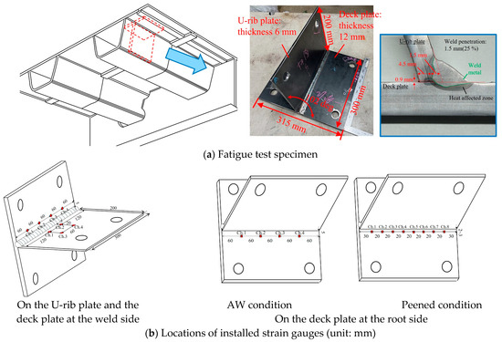
Figure 2.
Configuration of fatigue test specimen.

Table 1.
Mechanical properties and chemical composition.
Figure 2b shows the location of the strain gauges used in the experiments. Uniaxial strain gauges with a length of 1 mm were used. First, the stresses were calculated by multiplying the strain by the Young modulus of steel (200,000 MPa). Then, referring to a previous study, the stress obtained from 5 mm and 25 mm from the weld toe on the U-rib plate (hereafter referred to as the U-rib toe) was used to calculate the stress at the weld root. This is defined as the nominal stress [23]. Concretely, the weld throat bending moment range was obtained from them by linear extrapolation, and the bending stress range generated at the weld root was calculated using Equation (1) [23]:
where l is the distance between the 5 mm location and the weld root, and tr and tthroat are the thickness of the U-rib plate and the throat thickness, respectively. The throat thickness was measured individually on each cross section of the fatigue test specimens. To monitor the compressive residual stress induced by peening treatment around the weld root side, four strain gauges were glued around 10 mm from the weld toe on the deck plate (hereafter, deck-toe), and eight strain gauges were glued around 2 mm from the root edge (U-rib plate and deck plate intersection point) on the deck plate.
Table 2 shows the list of test specimens. In total, eight specimens were prepared. One of eight specimens was in an as-welded (AW) condition to confirm its fatigue strength. Seven specimens were in a peened condition. Specific peening cases are explained later in Section 2.2.2.

Table 2.
List of fatigue test specimens (※ corresponds with Figure 5).
2.2. Peening Treatment
2.2.1. Apparatus Used for Peening Treatment
Figure 3 shows the apparatus used for the peening treatment. A commercial cordless power scraper (hereafter, cordless HPICR apparatus) was adopted [24]. The cordless HPICR apparatus has a rectangular steel chipper whose size is 4 mm × 5 mm with rounded corners of R = 0.5 mm. The total weight, including the steel chipper and battery, is about 3.4 kg. The cordless HPICR apparatus is electrically driven, and its portability is so high that it is easy to use and bring it on-site. The feature of the cordless HPICR apparatus is that the dial can change the treatment frequency into five different levels. The minimum treatment frequency was about 16 Hz (level 1), while the maximum one was about 54 Hz (level 5). The same quality control method as HPICR using an air chipper, with a peening indent depth more than 0.2 mm [24], could be adopted for the cordless HPICR apparatus. To achieve the indent depth, all test specimens were first treated with the second dial (21.7 Hz) and then with a third dial frequency (31.7 Hz) and higher.
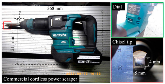
Figure 3.
Peening apparatus for hammer peening using a commercial cordless power scraper. Adapted from Ref. [24].
2.2.2. Peening Treatment Conditions
Figure 4 shows the peening treatment using the cordless HPICR apparatus. Figure 4a shows the situation of the cordless HPICR apparatus. The test specimen was fixed in a jig at 78 degrees using high-strength bolts, referring to the previous study [6]. A skillful operator performed the cordless HPICR apparatus around the weld bead of the test specimen. Note that it is confirmed that the effect of the cordless HPICR apparatus does not depend on the working position [24]. Figure 4b shows the confirmation of the peening indent depth by the cordless HPICR apparatus. A digital caliper was used to measure the peening indent depth at several points along the treated area, to confirm that quality control requirements had been met. Based on these experiments, achieving the target peening indent depth typically required around five peening passes.

Figure 4.
Peening treatment using the cordless HPICR apparatus.
Figure 5 shows the peening cases of the cordless HPICR apparatus. There are two cases, as shown in the figure. One case follows the method conducted in the previous study [15]. It is that the cordless HPICR apparatus is applied to the deck-toe only (Figure 5a). In the other case, it is applied to both the U-rib and the deck-toes (Figure 5b), aiming at inducing peen forming of the U-rib plate. One of seven specimens was peened 20 mm away from the U-rib toe (Figure 5c) to see how the peening location affects peen forming. The cordless HPICR apparatus on the U-rib side (U-rib toe and U-rib surface) was first engaged, and then the deck-toe was peened. When the treatment was performed at 20 mm, a jig was sandwiched between the ground and the U-rib because vibration by the cordless HPICR apparatus made the U-rib vibrate, and workability was excessively worsened. The cordless HPICR apparatus was positioned perpendicularly to either the deck plate or U-rib plate.
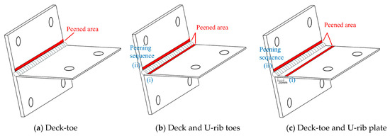
Figure 5.
Peening treatment cases of the cordless HPICR apparatus.
After the cordless HPICR apparatus procedure, to observe whether the U-rib plate was deformed, a mold around the welds was taken, and its angle was measured. In addition, deformation at the edge of the U-rib plate was monitored by using displacement meters, as shown in Figure 4c, to confirm how the U-rib plate is deformed while conducting the cordless HPICR apparatus procedure.
2.3. Results of Peening Treatment
2.3.1. Residual Stress Measurement by Using Strain Gauges
Figure 6 shows the measurement results of induced residual stress monitored at the root side of Nos. 2, 6, and 8. These stress values represent the stress component perpendicular to the weld. Figure 6a shows the results of the deck-toe peened specimen (No. 2). As shown in the figure, the amount of induced compressive residual stress into the weld root gradually increases with an increase in the number of cordless HPICR apparatus passes and finally reaches the range of −30 to −80 MPa. Figure 6b shows the results of the U-rib and deck-toes. The cordless HPICR apparatus at the U-rib toe tends to induce compressive residual stress of around −20 MPa at the edge of the test specimen. After the subsequent cordless HPICR apparatus procedure on the deck-toe, the compressive residual stress ranged from −50 to −100 MPa. Figure 6c shows the results of the U-rib plate, followed by the deck-toe (No. 8). It was found that the cordless HPICR apparatus on the U-rib plate does not introduce any compressive residual stress to the weld root side, as the peening location is 20 mm away from the weld toe. Also, the introduced compressive residual stress has a large scatter and is in the range of −20 to −100 MPa.
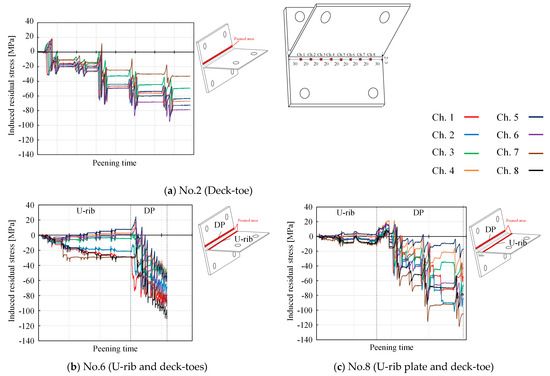
Figure 6.
Measurement results of induced compressive residual stress at the root side (perpendicular to the weld seam).
Therefore, it is found that compressive residual stress is somehow introduced at the root side when the cordless HPICR apparatus procedure is performed at the U-rib toe, and the resultant compressive residual stress field after the treatment at the deck-toe is almost the same range with and without the treatment for the U-rib side.
2.3.2. Deformation Measurement of the U-Rib Plate by Using Silicone and Displacement Meters
Figure 7 shows the deformation measurement results of the U-rib plate using silicone and displacement meters. Figure 7a shows the angle between the deck and the U-rib plates. Silicone was used to take a replica around the weld bead from the middle of the test specimen’s width. The silicone measurements taken from Nos. 2 and 8 show 102 degrees; this angle is the same as the angle at which the test specimen is assembled. Meanwhile, Nos. 5 and 6 slightly changed to a larger angle than 102 degrees. Figure 7b shows the measurement results by the displacement meters on No. 6. The side view of the test specimen before and after the cordless HPICR apparatus procedure is also shown. It is found that the deformation at the U-rib plate edge gradually increased and reached around 11 mm during the cordless HPICR apparatus procedure on the U-rib toe. An additional small displacement of around 2 mm was confirmed when the treatment was performed on the deck-toe. This is because the HPICR apparatus introduced compressive residual stress and its related plastic deformation into a surface layer of the U-rib plate, whose thickness is as thin as 6 mm, and elastic deformation is developed beneath the plastic deformation zone. This causes a negative moment, and the U-rib plate was bent in convex mode, like peen forming, as shown in Figure 8. This might be the reason why compressive residual stresses were introduced at the root side as shown in Figure 6b. It is found that this peen forming of the U-rib occurred by producing upward from the center of the peened area. Hence, this would be the reason why any change in the angle was not observed in the case of No. 8, although the treatment was conducted on the U-rib plate surface. Therefore, it is found that the deformation of the U-rib plate, i.e., peen forming, is caused by the peening treatment by both the U-rib and deck-toes.
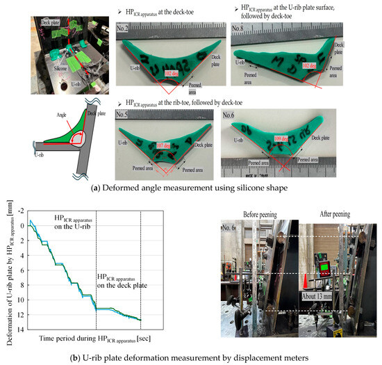
Figure 7.
Measurement results of deformation of the U-rib plate by the cordless HPICR apparatus.
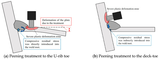
Figure 8.
Peen forming of the U-rib plate.
2.4. Fatigue Test
2.4.1. Fatigue Test Condition
Figure 9 shows the setup of the test specimen for the fatigue test. The jig that was used when the cordless HPICR apparatus method was performed continued to be used. The test specimens were fatigue-tested using a plate-bending fatigue test machine developed by Yamada et al. [25]. The test machine was mounted on the edge of the U-rib plate with the help of an extended steel plate. The test machine’s characteristic is that any range of bending force can be applied to the test specimen. Bending force is generated by the vibration of an eccentric mass inside the test machine. The frequency of the fatigue test can be controlled by a control box. It is noted that resonance always occurs when the test specimen’s natural frequency corresponds to the fatigue test’s frequency. The natural frequency of the test specimen was preliminarily investigated and found to be around 10 Hz, and hence, a frequency for the fatigue test was set as around 9 Hz to avoid resonance.
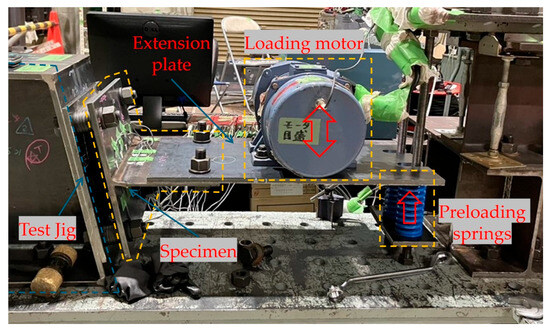
Figure 9.
Fatigue test setup of the specimen.
The fatigue test was performed under a stress ratio of around R = 0.0. The magnitude of the preload was monitored from the 5 mm strain gauges. Stress generated at the weld root due to the preload was calculated using Equation (1) and is summarized in Table 2. The fatigue test continued up to around 10 million cycles. If no fatigue crack initiation and/or propagation occurred, the fatigue test was considered a run-out and continued after an increase in the nominal stress range. After fatigue crack initiation, the beach-mark test was conducted with around half of the fatigue test frequency to confirm how the fatigue crack propagates in the weld bead. The fatigue test ended when the strain monitored on the 2 mm at the root side dropped around 50% from the initial value.
2.4.2. Fatigue Test Results
Figure 10 and Table 2 show fatigue test results. Fatigue design curves made by the Japanese Society of Steel Construction (JSSC) [4] are depicted. For the comparison of fatigue strength in the AW condition, the fatigue test results by Ya et al. [23] are also plotted in the figure. Some fatigue test specimens did not fail and reached the run-out, indicated by black arrows. Red dashed lines mean that the fatigue tests continued with an increase in the nominal stress range after the run-out.
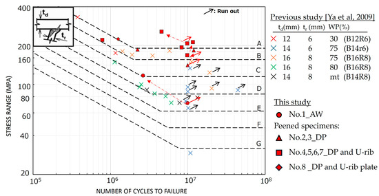
Figure 10.
Fatigue test results. Reprinted from Ref. [23].
From the fatigue test results of the AW condition, the fatigue test was first performed at a nominal stress range of 71 MPa and reached the run-out. Then, the nominal stress range was increased to 117 MPa, and the specimen failed. Its fatigue strength showed the JSSC-C class. Yamada et al. demonstrated that the fatigue strengths of test specimens using the same deck and U-rib plate thickness are JSSC-B or C [23]. Hence, it is found that the fatigue strength of the AW specimen is in good agreement with that of the previous study [23].
The fatigue test results of the cordless HPICR apparatus condition are then discussed. From the results of Nos. 2 and 3, one of the two specimens did not fail at the nominal stress range of 140 MPa, and both specimens failed at the nominal stress range of around 180 MPa. As a result, fatigue strengths show the JSSC-B class. These fatigue strengths are one class higher than those of the AW condition. From the No. 4, 5, 6, and 7 results, two of the four specimens started at the nominal stress range of around 170 to 180 MPa and reached the run-out. Then, the fatigue test continued at the nominal stress range of around 200 MPa. As a result, three specimens failed, and their fatigue strengths showed the JSSC-A class. The last specimen (No. 7) showed the JSSC-B class. This reason has been under investigation. From comparison with the results, it was found that the fatigue strengths of Nos. 4, 5, and 6 are clearly one class higher than that of Nos. 2 and 3. The main difference between them is treatment with or without peen forming. Peen forming can introduce higher compressive residual stress to the weld root than that by peening treatment at the deck-toe due to it is direct introduction of compressive residual stress to the weld root, as shown in Figure 6. Thus, the magnitude of compressive residual stress to the weld root is thought to be much higher than the latter one, and the fatigue strength of test specimens No. 4, 5, and 6 becomes stronger than that of Nos. 2 and 3. Hence, peening treatment on both the U-rib and the deck plate toes resulted in peen forming of the U-rib plate, consequently achieving one JSSC class higher fatigue life than with deck-toe peening only. Therefore, it can be concluded that peen forming, as an extended peening treatment method, is effective for obtaining fatigue life extension of the weld root in OSDs.
Note that it is difficult to discuss quantitatively how much compressive residual stress has been introduced locally at the weld root from the experiment. Hence, a finite element analysis of the peening treatment with the representation of peen forming is carried out and discussed in the next chapter.
2.4.3. Observation of Fractured Surface
Figure 11 shows the fractured surfaces of Nos. 1, 3, 5 and 8. From observation, it was found that the fatigue cracks initiated from the weld root at the base plate side, as the leftover or weld root side could be seen on the fractured surface of the U-rib side. Hattori et al. [26] observed in their experiments that fatigue cracks initiated from the weld root on both the U-rib and the deck plate side, with the former being more probable. However, in this study, fatigue cracks always initiated from the deck plate side. The specific reason for this is unknown, but it should be noted that this does not interfere with the aim of the study. From Figure 11b, multiple fatigue cracks initiated from the weld root. According to SEM observation, the crack initiation site would be the interface that existed in the weld root. After some crack propagation, these fatigue cracks were merged into one large semicircular shape, which then went through the weld bead. In the case of No. 5, multiple weld imperfections whose maximum size was around 4 mm were observed around the crack initiation site. Despite including weld imperfections, the fatigue life of No. 5 was longer than that of No. 3. Therefore, from this point of view, it is inferred that the effect of fatigue life enhancement by peen forming is more significant than peening treatment by deck-toe peening only.
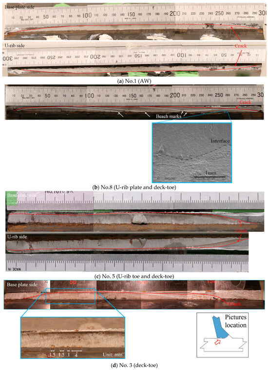
Figure 11.
Fractured surfaces of Nos. 1, 3, 5, and 8.
3. Finite Element Analysis
3.1. Numerical Simulation of Peening Treatment
3.1.1. Simulation Model
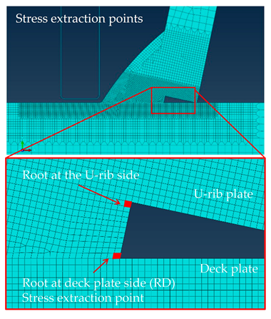
Figure 12 shows the simulation model. The simulation model consists of two parts. One is the test specimen, and the other is the pin used for the cordless HPICR apparatus. Two-dimensional shapes of both parts were modeled according to the dimensions of the cross section of the test specimen and the pin. Detailed information about the test specimen model is first explained. The weld size of the test specimen model is 6 mm × 6 mm, and its weld root is a triangular shape. To consider residual stress around the weld root due to the manufacturing process, i.e., welding, welding simulation would be one option. However, it is difficult to capture stress directly, and validating it is a challenge even if a welding simulation is performed. Therefore, for simplicity, the authors did not consider residual stress due to welding in this simulation.
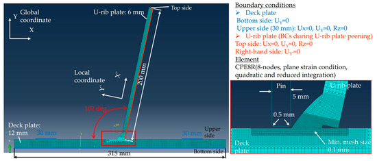
Figure 12.
Simulation model.
The test specimen model was designed with a deformable body. Young’s modulus and Poisson’s ratio were 207,500 MPa and 0.28, respectively. Von Mises’ criteria for material yielding were adopted. A combined hardening model was employed to represent the plastic behavior of the test specimen model after yielding. The combined hardening parameters calibrated from mild steel by Foehrenbach et al. [27] was used due to the similar yield strength of the test specimen (see Table 1). Table 3 shows the combined hardening parameters. Note that strain-dependent hardening was not considered in this study. The minimum element size of 0.1 mm was assigned around the weld bead of the test specimen model, as shown in Figure 12. The element type used was CPE8R, which is an eight-node, quadratic plane strain condition with reduced integration. Detailed information on the pin model is then described. The pin model is a small part with a length of about 18 mm. The bottom of the pin model is a flat surface of 5 mm with a rounded corner of 0.5 mm. The pin is set so that its right side corresponds to the weld toe on the base plate. The contact surfaces of the pin and the test specimen model are defined as the master and slave surfaces, respectively. The friction between the pin and the test specimen models is defined as Coulomb friction, and the friction coefficient µ is set as 0.0 [28].

Table 3.
Combined hardening parameters calibrated by Foehrenbach et al. (Reprinted from Ref. [27]). Upper row: kinetic hardening component; lower row: isotropic hardening component.
Figure 12 also shows the boundary condition of the simulation model. The bottom of the deck plate of the test specimen model is considered to provide vertical support (Uy = 0) and to represent the fatigue test condition; the bolted area, where the length is 30 mm, is fixed and depicted with blue lines. For the top side of the U-rib plate, Ux = 0, Uy = 0, and Rz = 0 is applied. A temporary boundary condition at the right-hand side of the U-rib plate is considered when peening on the U-rib plate to achieve the desired peening depth.
3.1.2. Simulation Cases of Peening Treatment
Figure 13 shows the simulation cases of peen treatment. Peening treatment using the cordless HPICR apparatus was numerically simulated. For the sake of simplicity, the pin strike movement is represented by the enforced displacement given to the pin model. This type of static analysis is called a displacement-controlled simulation, e.g., [29]. The pin strikes the test specimen model once to reach a certain indentation depth, and then it is forcibly pulled out. The depth is 0.3 mm, the same as in the experiments. According to the experiment discussed in Section 2, three peening cases are assumed, as shown in Figure 13a. The peening cases are the deck-toe, the U-rib and the deck-toes, and the U-rib plate at 20 mm from the U-rib toe and the deck-toe. The numbers depicted in Figure 13a indicate the order of the peening treatment.
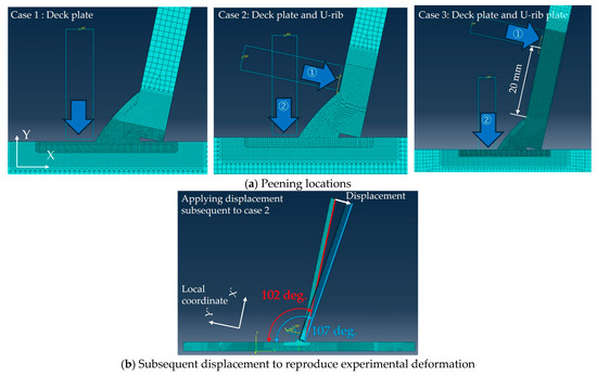
Figure 13.
Simulation cases of peening treatment. The numbers depicted in (a) indicate the order of the peening treatment.
For case 2, the influence of peen forming on residual stress at the weld root is investigated. Figure 13b shows the procedure. After the simulation of the peening treatment is completed, the boundary condition given to the right side of the U-rib plate is released. Then, the angle of the U-rib is forcibly bent from 102 to 107 degrees. To create this degree change, around 14 mm displacement is given to the edge of the U-rib instead of applying a negative moment due to peen forming. This is because the establishment of a simulation model that can represent peen forming requires a lot of effort, e.g., modeling the weld root and the choice of material property around the weld root, the consideration of welding residual stresses, and so on, and even though the establishment is made, direct comparisons of how large compressive residual stresses are introduced into the weld root stress are difficult. Hence, its accuracy cannot be validated. Thus, a straightforward way of applying displacement to the test specimen model after peening treatment is first adopted in this study.
3.1.3. Validity of Numerical Simulation of Peening Treatment
Before the numerical simulation, its validity is confirmed by comparing the experimental and simulation results. Figure 14 shows the simulation results of case 1. The stress component in the X-direction is shown. This figure depicts a numerical simulation result previously conducted by Tsutsumi et al. [16]. Moreover, compressive residual stresses measured near the deck plate beside the weld toe and the root side are also included. Compared to the current simulation results, Tsutsumi [16] showed much higher compressive residual stress at the weld root. The difference is around 40%. This could be due to the difference in the simulation method. They employed thermal expansion strains to reproduce the plastic strain derived from hammer peening. The comparison of the experimental and numerical results shows that the simulation result captures the experimental results well, and the difference between them is less than 10%. Therefore, it can be judged that the numerical simulation model is valid enough to simulate compressive residual stress introduced by the cordless HPICR apparatus.
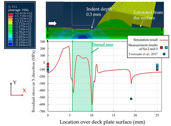
Figure 14.
Comparison of experimental and numerical results for validation. Reprinted from Ref. [16].
3.2. Numerical Simulation Results
Figure 15 shows the numerical simulation results as induced residual stress contours. These stress contours represent minimum principal stresses. From the results of cases 1, 2, and 3, the minimum principal stress can be seen at the weld root of the deck plate side. These values are around −200 MPa. From the result of the application of deformation after the peening treatment in case 2, it can be seen that the blue contour area is significantly expanded. Table 4 shows the minimum principal stress extracted from the crack initiation point at the weld root of the deck plate side. After the application of deformation, the value at the weld root of the deck plate side was around −600 MPa. In this table, the stress at the weld root of the U-rib side, which is a more common crack initiation site, is shown. In addition, stress values with 160 and 200 MPa pre-loading at the 5 mm location are also shown. After applying 160 MPa, it was found that the minimum principal values at the weld root of the deck plate side are either in tension or around zero in cases 1 and 3 but still in compression in case 2. Hence, fatigue failure occurred in the former case and did not occur in the latter case. This captures the trend in the experiment results shown in Table 2 well. Therefore, the higher fatigue strength enhancement observed in the experiment can be attributed to the high compressive residual stress introduced around the weld root by peen forming.
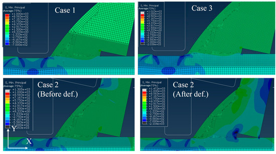
Figure 15.
Numerical simulation results (min. principal stress contours).

Table 4.
Minimum principal stress extracted from the weld root.
4. Conclusions
The results of this study support the following conclusions:
- It was found that peening treatment of both the U-rib and deck plate toes causes a deformation in the U-rib plate, i.e., peen forming.
- The fatigue test under R = 0.0 showed that the fatigue test specimens with peen forming have higher fatigue life (JSSC-A class) compared to those peened at the deck-toe only (JSSC-B class).
- Observation of the fractured surface revealed that fatigue cracks are initiated from the weld root of the deck plate side in both cases, with and without peening treatment.
- Simulation results showed that peen forming, which is reproduced by applying displacement subsequent to peening treatment simulation, can introduce about three times higher compressive residual stress at the weld root of the deck plate side than that by peening treatment to the deck-toe only. Also, the introduced compressive residual stresses around the weld root by peen forming were kept even after applying a pre-load of around 200 MPa at 5 mm away from the U-rib toe.
- Therefore, it can be concluded that peen forming, as an extended peening treatment utilization, is highly effective in enhancing the fatigue life of the weld root in OSDs.
It should be noted that although the fatigue life of the weld root of OSDs can be obtained by peen forming of the U-rib plate, quality control methods, e.g., how much forming is required and how the peen forming shape is controlled, would be necessary to achieve certain fatigue life enhancement. Also, the effect of fatigue life enhancement would be changed by thicker U-rib plates due to the change in stiffness; hence, this would need to be investigated. Furthermore, the used test specimen is a small part of rib-to-deck welded joints in OSDs, and its boundary condition differs widely from the actual structural condition. Therefore, it is highly recommended that the investigation and verification of whether peen forming of the U-rib is possible and how it will be formed under actual conditions be conducted.
Author Contributions
Conceptualization, N.A. and K.K.; Methodology, N.A., Y.B. and K.K.; Validation, N.A. and Y.B.; Formal Analysis, N.A. and Y.B.; Investigation, N.A. and Y.B.; Resources, K.K.; Data Curation, N.A.; Writing—Original Draft Preparation, N.A. and Y.B.; Writing—Review And Editing, Y.B. and K.K.; Visualization, N.A. and Y.B.; Supervision, Y.B. and K.K.; Project Administration, K.K.; Funding Acquisition, K.K. All authors have read and agreed to the published version of the manuscript.
Funding
This research was funded by Central Nippon Highway Engineering Nagoya Co., Ltd., under the joint research project titled “Research and development on fatigue durability of orthotropic steel decks using ICR treatment”.
Data Availability Statement
The raw data supporting the conclusions of this article will be made available by the authors on request.
Acknowledgments
The authors acknowledge Onda Naoaki, Eita Hatanaka, and Toshiyuki Onoyama at Central Nippon Highway Engineering Nagoya Co., Ltd., for their significant support, such as preparing fatigue test specimens and conducting cordless ICR treatment of the specimens.
Conflicts of Interest
The authors declare no conflict of interest.
References
- Ahmadivala, M.; Berthellemy, J.; Orcesi, A.; Mattrand, C.; Gayton, N.; Yalamas, T. A Strategy for Rib-to-Deck Crack Propagation Analysis and Strengthening of Orthotropic Deck Bridges. Eng. Fail. Anal. 2022, 134, 106057. [Google Scholar] [CrossRef]
- Connor, R.; Fisher, J.; Gatti, W.; Gopalaratnam, V.; Kozy, B.; Leshko, B.; McQuaid, D.L.; Medlock, R.; Mertz, D.; Murphy, T.; et al. Manual for Design, Construction, and Maintenance of Orthotropic Steel Deck Bridges; US Department of Transportation Federal Highway Administration: Washington, DC, USA, 2012; p. 291.
- Kolstein, M.H. Fatigue Classification of Welded Joints in Orthotropic Steel Bridge Decks. Ph.D. Thesis, Delft University of Technology, Delft, The Netherlands, 12 June 2007. [Google Scholar]
- Japan Road Association Highway Bridge Specifications. Fatigue Design Guidelines for Steel Bridges; Japan Road Association Highway Bridge Specifications: Tokyo, Japan, 2002. (In Japanese)
- Tsakopoulos, P.A.; Fisher, J.W. Full-Scale Fatigue Tests of Steel Orthotropic Deck Panel for the Bronx-Whitestone Bridge Rehabilitation. Bridg. Struct. 2005, 1, 55–66. [Google Scholar] [CrossRef]
- Ya, S.; Yamada, K.; Ishikawa, T. Fatigue Durability of Trough Rib to Deck Plate Welded Detail of Some Orthotropic Steel Decks. J. Struct. Eng. 2010, 56, 77–90. [Google Scholar]
- Ocel, J.M.; Cross, B.; Wright, W.J.; Yuan, H. Optimization of Rib-to-Deck Welds for Steel Orthotropic Bridge Decks; United States Federal Highway Administration: Washington, DC, USA, 2017; p. 339.
- Da, L.T.; Zhang, Q.H.; Yuan, D.Y.; Ma, Y.; Cui, C.A. New Orthotropic Steel Deck System Incorporating Two Novel Structural Details. J. Constr. Steel Res. 2022, 199, 107633. [Google Scholar] [CrossRef]
- Wang, D.Q.Q.; Yao, D.D.; Gao, Z.B.; Wang, Q.; Zhang, Z.F.; Li, X.W. Fatigue Mechanism of Medium-Carbon Steel Welded Joint: Competitive Impacts of Various Defects. Int. J. Fatigue 2021, 151, 106363. [Google Scholar] [CrossRef]
- Ju, X.; Tateishi, K. Fatigue Crack Behavior at Rib-to-Deck Weld Bead in Orthotropic Steel Deck. Adv. Struct. Eng. 2014, 17, 1459–1468. [Google Scholar] [CrossRef]
- Marquis, G.B.; Barsoum, Z. IIW Recommendations on High Frequency Mechanical Impact (HFMI) Treatment for Improving the Fatigue Strength of Welded Joints; Springer: Singapore, 2016; pp. 1–34. [Google Scholar]
- Tai, M.; Miki, C. Fatigue Strength Improvement by Hammer Peening Treatment—Verification from Plastic Deformation, Residual Stress, and Fatigue Crack Propagation Rate. Weld. World 2014, 58, 307–318. [Google Scholar] [CrossRef]
- Lefebvre, F.; Peyrac, C.; Elbel, G.; Revilla-Gomez, C.; Verdu, C.; Buffière, J.Y. HFMI: Understanding the Mechanisms for Fatigue Life Improvement and Repair of Welded Structures. Weld. World 2017, 61, 789–799. [Google Scholar] [CrossRef]
- Chan, W.L.; Cheng, H.K.F. Hammer Peening Technology—The Past, Present, and Future. Int. J. Adv. Manuf. Technol. 2022, 118, 683–701. [Google Scholar] [CrossRef]
- Matsumoto, R.; Rockenbach, J.; Ishikawa, T.; Hattori, A.; Kouno, H. Fatigue Strength Improvement of Weld Root between Steel Deck Plate and Trough Rib. Struct. Eng. Pap. A 2017, 63, 668–680. (In Japanese) [Google Scholar]
- Tsutsumi, S.; Nagao, R.; Fincato, R.; Ishikawa, T.; Matsumoto, R. Numerical and Experimental Study on Fatigue Life Extension of U-Rib Steel Structure by Hammer Peening. Proc. Proc. Jpn. Weld. Soc. 2017, 35, 169s–172s. [Google Scholar] [CrossRef][Green Version]
- Shimanuki, H.; Yonezawa, T.; Tanaka, R. Investigation on Fatigue Prevention Method for the Weld Root of U-Rib in OSDs Utilizing Compressive Residual Stress. In Proceedings of the 72th Annual Conference of the Japan Society of Civil Engineers, Fukuoka, Japan, 11–13 September 2017. (In Japanese). [Google Scholar]
- Tsutsumi, S.; Shibata, H.; Fincato, R.; Yonezawa, T.; Shimanuki, H. Effect of Pre-Overload on Fatigue Life Extension of u-Rib Steel Floor Slab Root. Yosetsu Gakkai Ronbunshu Q. J. Jpn. Weld. Soc. 2021, 38, 177s–181s. [Google Scholar] [CrossRef]
- Ohta, T.; Sato, Y. Numerical Analysis of Peen Forming for High-Strength Aluminum Alloy Plates. Mater. Trans. 2021, 62, 846–855. [Google Scholar] [CrossRef]
- Faucheux, P.A.; Gosselin, F.P.; Lévesque, M. Simulating Shot Peen Forming with Eigenstrains. J. Mater. Process. Technol. 2018, 254, 135–144. [Google Scholar] [CrossRef]
- Zhou, W.F.; Ren, X.D.; Wang, C.C.; Yang, X.Q.; Larson, E.A. Residual Stress Induced Convex Bending in Laser Peen Formed Aluminum Alloy. J. Laser Appl. 2018, 30, 012001. [Google Scholar] [CrossRef]
- Ahmadzai, N.; Banno, Y.; Onda, N.; Hatanaka, E.; Nakata, E.; Kinoshita, K. Investigation of the Effect of Hammer Peening with ICR Apparatus on Weld Root of U-Rib to Deck Welded Joints in Orthotropic Steel Deck. Proc. Constr. SteelV 2024, 32, 124–132. [Google Scholar]
- Ya, S.; Yamada, K.; Ishikawa, T.; Murai, K. Fatigue Evaluation of Trough Rib to Deck Plate Joint Failed in Weld Throat. Steel Struct. J. 2009, 16, 11–20. [Google Scholar]
- Banno, Y.; Sugawa, K.; Arima, N.; Taga, S.; Kinoshita, K. Fatigue Strength Improvement Effect of Welded Joints Peened by ICR Treatment Using a Chargeable Electric Device. J. Struct. Eng. 2024, 70, 398–414. (In Japanese) [Google Scholar]
- Yamada, K.; Ojio, T.; Torii, A.; Baik, B.; Sasaki, Y.; Yamada, S. Influence of shot blasting on fatigue strength of out-of-plane gusseted specimens under bending. J. Struct. Eng. 2008, 54, 522–529. (In Japanese) [Google Scholar]
- Hattori, M.; Tateishi, K.; Hanji, T.; Shimizu, M. Fatigue Strength Evaluation by measurable Stresses for Root Cracks in U-rib to Deck Welded Joints of Orthotropic Steel Decks. Int. Inst. Weld. 2023, 67, 2273–2282. (In Japanese) [Google Scholar] [CrossRef]
- Foehrenbach, J.; Hardenacke, V.; Farajian, M. High Frequency Mechanical Impact Treatment (HFMI) for the Fatigue Improvement: Numerical and Experimental Investigations to Describe the Condition in the Surface Layer. Weld. World 2016, 60, 749–755. [Google Scholar] [CrossRef]
- Nakanishi, K.; Morikage, K.; Kawabata, A.; Tomo, H. Study on Improvement Method of Fatigue Strength of Welded Joints by Hammer Peening on Base Metal. Jpn. Soc. Civ. Eng. Proc. A1 (Struct. Earthq. Eng.) 2015, 71, 10–19. [Google Scholar]
- Khurshid, M.; Leitner, M.; Barsoum, Z.; Schneider, C. Residual Stress State Induced by High Frequency Mechanical Impact Treatment in Different Steel Grades—Numerical and Experimental Study. Int. J. Mech. Sci. 2017, 123, 34–42. [Google Scholar] [CrossRef]
Disclaimer/Publisher’s Note: The statements, opinions and data contained in all publications are solely those of the individual author(s) and contributor(s) and not of MDPI and/or the editor(s). MDPI and/or the editor(s) disclaim responsibility for any injury to people or property resulting from any ideas, methods, instructions or products referred to in the content. |
© 2025 by the authors. Licensee MDPI, Basel, Switzerland. This article is an open access article distributed under the terms and conditions of the Creative Commons Attribution (CC BY) license (https://creativecommons.org/licenses/by/4.0/).
