Abstract
Welding and cutting behaviour may affect the mechanical properties of titanium alloy welded structures, which may have some impact on the safety assessment of the structure. This study analyses changes in residual stress in Ti80 butt-welded thick plates before and after wire-cut electric discharge machining, using numerical simulations based on thermo-elastoplastic theory and the element birth and death method, validated by X-ray non-destructive testing. The transverse residual tensile stress near the weld exhibits an asymmetric bimodal distribution, while the longitudinal stress is significantly higher than the transverse stress. Wire-cut electric discharge machining had minimal influence on the transverse residual stress distribution but led to partial relief of the longitudinal residual tensile stress. The maximum reductions in transverse and longitudinal welding residual tensile stresses are approximately 60% and 36%, respectively. The findings indicate that wire-cut electric discharge machining can alter surface residual stresses in Ti alloy butt-welded thick plates. This study also establishes a numerical simulation methodology for analysing welding residual stresses and their evolution due to wire-cut electric discharge machining. The results provide a theoretical basis for analysing the structural strength and safety of Ti-alloy-based deep-sea submersibles.
1. Introduction
Titanium alloys have become key structural materials for the lightweight design of deep-sea pressure-resistant structures owing to their low density, high strength, and excellent corrosion resistance in marine and atmospheric environments [1]. Currently utilised in marine applications, such as deep-sea submersibles, most deep-sea equipment is fabricated through welding processes, inevitably resulting in welding residual stresses. For example, deep-sea spherical submersibles form equatorial weld seams (circumferential welds) via butt welding [2,3]. Cutting is also a common fabrication method and may influence the residual stresses in Ti alloy butt-welded thick plates [4]. While there will be a large residual tensile stress, the existence of residual tensile stress will have a negative impact on the structural performance and the fatigue life of the structure. For example, on 12 November 1983, on the U.S. Amtrak No. 21 passenger train line to Woodlawn, Texas, the railroad tracks suddenly broke at waist height along the length of the track, causing the train to derail; it was determined that the fatigue damage caused by welding residual stresses led to the accident [5]. Owing to the potential impact of these stresses on structural performance and safety, and the need for accurate numerical simulations involving these effects, the investigation of simulation methodologies that capture cutting-induced residual stress in Ti alloy butt-welded thick plates is particularly crucial.
Arunkumar et al. [6] predicted the temperature field and weld residual stress field during the weld process of Ti-6Al-4V by ANSYS numerical simulation and experimental verification. Liu et al. [7] studied the residual stress of welding titanium alloy thick plates through the comparison and verification of three-dimensional and two-dimensional finite element models and experimental tests. Kumar et al. [8] verified the effect of laser welding on the residual stress field of Ti-6Al-4V alloy through numerical simulation and experiment. Although there are many studies in the literature on the residual stress of titanium welding plates, these only study the welding and do not study the effect of cutting after welding on the residual stress of welding. Yang et al. [9,10] utilized coupled thermo-mechanical finite element methods to analyse the residual stress field in structural steel thick plates caused by thermal cutting, revealing the release mechanism of the initial residual stress in structural steel during cutting. Wang et al. [11] simulated the cutting process of titanium alloy through Abaqus and found different cutting effects on the residual stress of titanium alloy structure. Yan et al. [12] compared the evolution laws of residual stress before and after cutting in aluminium alloy thick plates with those of the initial residual stress through finite element simulation and experimental verification; the residual stress release mechanism in aluminium alloy plates after cutting was also investigated. Although the numerical simulation method of the effect of cutting on residual stresses of plates in literature 9–12 is similar to this this study, it does not consider the effect of welding. Wang et al. [13] established a simplified distribution model of post-weld flame cutting residual stress for Q460 high-strength steel H-shaped sections through comparative verification using drilling and sectioning methods. Dattoma et al. [14] comparatively analysed the redistribution patterns of residual stress in hot-rolled structural steel-plate butt welds after post-weld cutting through numerical simulations and experiments. Due to an almost complete lack of studies of the effect of cutting on residual stress after welding of titanium alloy, literature 13 and literature 14 related to structural steel are cited, in addition to literature 13 about the steel H-section, and literature 14 about the plate maximum thickness not exceeding 20 mm. In addition, there is all only one straight path for cutting described in in literature 13–14. The novelty of the current paper is the quantitative analysis of the variation of the residual stress of titanium alloy butt-welded thick plates (42 mm thickness) after cutting; moreover our cutting path is ring-shaped, which is different from the one straight path described in literature 9–14. The high cost of Ti alloys results in less Ti-based equipment being constructed, which limits research advancements in this field. With the reduction in Ti alloy costs, the manufacturing of Ti-based deep-sea equipment is gradually increasing in pace.
Therefore, in this paper, in order to ensure accuracy and calculation efficiency, a more efficient numerical calculation method is adopted, based on the thermoelasticity and plasticity theory, the life and death unit and the highest temperature method, to carry out numerical calculations and experimental validation to analyse the effect of the cutting processing on the residual stresses of titanium alloy butt-welded thick plate. A numerical simulation methodology for predicting the welding residual stress fields in post-cutting Ti alloy butt-welded thick plates was established. The highest temperature method is to simulate the temperature of the welding process according to the maximum temperature of the actual welding process. The research findings provide foundational support for future studies on the evolution of mechanical properties in Ti alloy welded structures, while also offering a theoretical basis for the structural strength and safety reliability analysis of deep-sea submersibles constructed using Ti alloys.
2. Theoretical Basis of Related Research
The finite element method is a commonly used and effective approach for studying the temperature and stress fields during the welding process. This study employed the thermo-elastoplastic finite element method and a predefined temperature heat source model [15,16]. The melting temperature of the material is used as the welding temperature, the melting temperature is applied to the unit on the corresponding weld pass and maintained for a certain period of time, and the welding process is simulated by the life-death unit technology to simulate the gradual filling process of titanium alloy metal during the welding process, thus realising the numerical simulation of the welding process. First of all, to inhibit the unit at the weld pass (for which the technical term is ‘kill’, in ANSYS2023 software), it will be welded at the unit mass, stiffness, specific heat, etc., multiplied by a very small factor (default 1.0 × 10⁻⁶) after the results of the approximate 0. The unit killed can be regarded as non-existent. Then, through the continuous sequential ‘activation’ of the unit, the ‘activated’ unit mass, stiffness, etc. is no longer multiplied by a very small factor, to restore the corresponding parameters of its own material to simulate the actual welding process of the weld metal gradual filling. Subsequently, the elements were sequentially activated to restore the material parameters and simulate the actual filling process of the weld metal during welding [17]. The melting temperature of the material is used as the cutting temperature, the melting temperature is applied to the units on the corresponding cutting pass and kept for a period of time, and the process of the gradual disappearance of the titanium alloy metal is simulated by the life and death units technology to achieve the numerical simulation of the cutting process. After applying the temperature to the units on the corresponding cutting pass, the unit which the temperature is applied is ‘killed’ after simulating the cutting process, thus treating the cut part as if it is non-existent, and repeating this process to achieve the simulation of the cutting process [12].
2.1. Basic Theory of Temperature Fields
Differential equations and boundary conditions for the temperature field are shown below.
The temperature field during the welding process [18,19] can be written as:
where is the temperature distribution, [], is the specific heat capacity of the material, [J/kg·], is the density of the material, [kg/], is the thermal conductivity of the material, is the intensity of the heat energy inside, [J], is the time required for heat transfer, [s], and the parameters , , all change with temperature. Arbitrarily choose a direction, such as the direction of temperature decreases until zero, and the equations of Equation (1) can be simplified to describe the heat conduction problem in two dimensions. Teat conduction differential equation is shown below:
2.2. Law of Convective Heat Transfer
2.2.1. The Law of Convective Heat Transfer
During the welding process, an uneven temperature distribution on the surface of the welded structure leads to heat exchange between the component surface and surrounding air. The basic formula for convective heat transfer is
where is the heat flux, [], is the convective heat transfer coefficient (also called the film heat transfer coefficient, interfacial thermal coefficient, or film coefficient), is the temperature of the solid surface, [], and is the temperature of the surrounding fluid.
2.2.2. The Law of Radiative Heat Transfer
The process by which an object in nature absorbs and transfers energy in the form of radiation without relying on a medium is known as radiative heat transfer. In general, objects with higher temperatures radiate more heat per unit time, and this form of heat transfer is prevalent in various welding processes. In engineering practice, radiation often considers two or more objects, and each object radiates to each other and absorbs heat. Thus, the transfer of heat between them can be calculated using the Stefan–Boltzmann equation, which is as follows:
where is the heat flow density, is the blackness coefficient of the object, i.e., the radiance, is the radiation coefficient of an absolute blackbody, i.e., the Stefan–Boltzmann constant, denotes the area of the radiating surface 1, denotes the shape coefficient, denotes the absolute temperature of the radiating surface 1, denotes the absolute temperature of the radiating surface 2.
2.3. Finite Element Simulation of Welding Temperature Field
The nodal temperatures within a single element can be assumed to exhibit a linear distribution in the spatial domain [20,21,22]. If the spatial domain is discretised, the relationship between them is as follows:
where is the shape function and are the nodal temperatures.
Subsequently, the weighted parameter method yields the following equation:
where , , and are global coefficient matrices, all functions of temperature. and are the temperatures of all the nodes and their temporal rate of change, respectively.
2.4. Welding Stress–Strain Relationship Field
Under the influence of high-temperature loading, the material undergoes plastic deformation [23,24]. The stress–strain relationship can be expressed as
where is the incremental stress, is the incremental strain, is the elastic or plastic matrix, and is a temperature-dependent vector, is the temperature increment.
In the elastic zone:
where is the linear expansion coefficient and is the corresponding temperature, is the elasticity matrix of the material, containing information such as Young’s modulus, Poisson’s ratio, etc., is the temperature-dependent vector in the elastic range.
In the plastic zone, the yield criterion for the material is
where is the yield function, and changes when the temperature and plastic deformation change. Following the plastic flow rule, the incremental plastic strain can be expressed as
At this stage:
where is the plasticity multiplier, is the plasticity matrix of the material, is the bias stress tensor. Unloading in the plastic zone can be determined using the value of ; when , the process is identified as unloading.
3. Experimental and Numerical Simulation Studies of Welding Residual Stress in Ti80 Thick-Plate Butt Joints
3.1. Experimental Study
3.1.1. Welding Process
The butt-welded thick plate under investigation was fabricated by joining two Ti80 thick plates (500 mm × 250 mm × 42 mm) using gas-shielded manual arc welding with double-sided alternating welding. The width of the surface weld bead was 25 mm, and it featured a double-V groove configuration with 32 weld passes. The post-weld dimensions measured 500 mm × 500 mm × 42 mm. The distribution of Ti80 butt weld thick plate weld passes is shown in Figure 1. The dimensions of the Ti80 butt-welded thick plate are shown in Figure 2. During welding, the four corners were constrained as shown in Figure 3. The weld filler material was identical to the base metal. Welding shielding gas using 99.99% argon, gas flow rate of 25 L/min, welding speed of 20 mm/min constant, with the welding parameters set at 25 A current and 125 V voltage. The initial welding temperature was maintained at 25 °C. The inter layer temperature of the weld pass is 100 °C or less.

Figure 1.
Ti80 butt welding thick plate weld passes arrangement diagram.
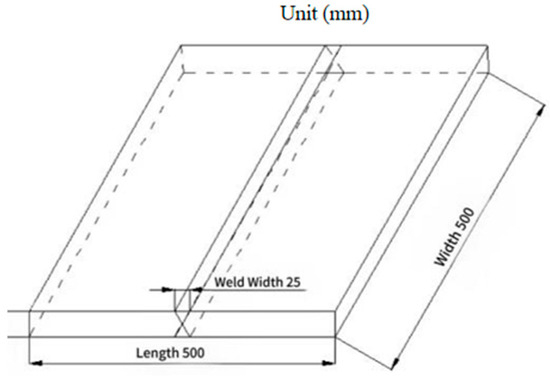
Figure 2.
Ti80 butt-welded thick plate size.
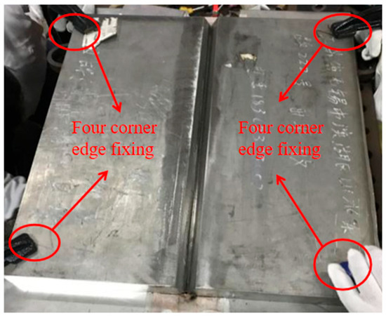
Figure 3.
Ti80 boundary conditions for Ti80 butt-welded thick plates.
3.1.2. Welding Residual Stress Testing
Harmful welding residual stresses inevitably occur during the welding process. These stresses seriously threaten the service life of the structure. Measurement methods for residual stresses can be generally categorised into destructive and non-destructive testing methods [25]. Non-destructive testing methods, including ultrasonic, X-ray and neutron diffraction methods, have the advantage of not damaging or affecting the performance of the tested parts [26], and are therefore widely used. Therefore, in this study, X-ray non-destructive testing was employed to experimentally investigate the welding residual stress in the fabricated Ti80 butt-welded thick plate before wire-cut electric discharge machining (Figure 4). The surface containing the final weld pass of the Ti80 butt-welded thick plate was defined as its upper surface (Figure 5). The residual stress measuring equipment adopts the X-ray non-destructive testing system (Canadian Residual Stress Testing and Analysis System LXRD MG2000, Proto Co., Ltd., Ottawa, ON, Canada). Residual stress measurements are carried out using X-ray related standards and procedures [27]. The geometric centre of the upper surface was designated as origin O, with the X-axis perpendicular to the weld line through origin O and the Y-axis aligned along the centreline of the weld width, as shown in Figure 5.
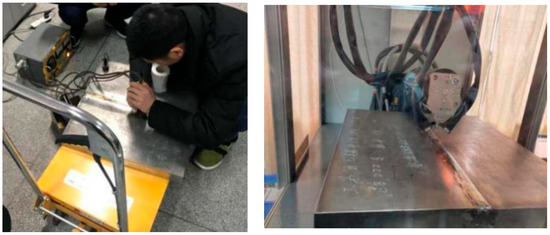
Figure 4.
Ti80 butt-welded thick plate profiling and testing process.
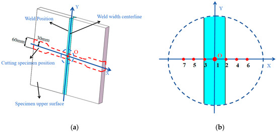
Figure 5.
Layout of measurement points and paths. (a) Coordinate systems and paths (b) Magnified view of the measurement point.
The transverse welding residual stress of the Ti80 butt-welded thick plate was defined along the X-axis, whereas the longitudinal welding residual stress was defined along the Y-axis. The positions and test results of measurement points 1–7 along the X-axis residual stress path on the upper surface are summarised in Table 1 and presented in Figure 5 and Figure 6. From Table 1 and Figure 6, the transverse welding residual stress along the X-axis exhibits an asymmetric double-peak distribution near the weld zone, with a maximum tensile stress of approximately 655 MPa. The simulation results of the longitudinal welding residual stress (Y-axis) before and after cutting are shown in Figure 7.

Table 1.
Measuring point location and residual stress test results before and after wire-cut electric discharge machining.
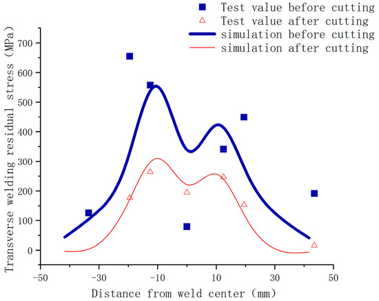
Figure 6.
Test and simulation results of transverse welding residual stress (X-axis) before and after cutting.
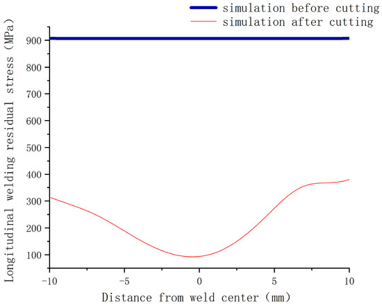
Figure 7.
Simulation results of longitudinal welding residual stress (Y-axis) before and after cutting.
3.2. Numerical Simulation of Welding Residual Stress
A finite element model was established for the Ti80 butt-welded thick plate (Figure 2). The mesh was refined in the weld zone and adjacent regions, and coarser mesh divisions were applied to the areas distant from the weld and cutting paths to ensure computational accuracy [28]. The size of the unit at the weld and the cutting seam is 3 mm, the size of the unit in the transition section near the weld seam is 10 mm, and the size of the unit at the farthest end of the weld seam is 15 mm. The total number of structural units is 27,000. The four corners of the plate were constrained (Figure 3), as shown in Figure 8. Residual stress before welding thick plate cutting is shown in Figure 9
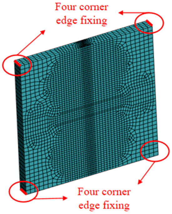
Figure 8.
Finite element model of butt-welded thick plate.
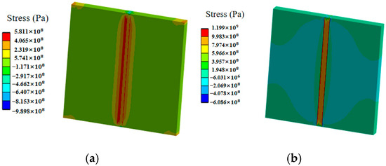
Figure 9.
Welding residual stress before cutting of butt-welded thick plate. (a) Transverse welding residual stress (b) Longitudinal welding residual stress.
The Ti80 butt-welded thick plate material exhibited a yield strength of approximately 800 MPa, tensile strength of 913 MPa, yield-to-tensile ratio of 0.87, and Poisson’s ratio of 0.3 at room temperature. The initial welding temperature was set to 25 °C. The convective heat transfer coefficient was set to 62.5 [29]. The radiant heat dissipation coefficient is 0.4. Temperatures for welding simulations are expressed in degrees Celsius. The physical properties of Ti80 are listed in Table 2. The stress versus strain curves for Ti80 at different temperatures are shown in Figure 10.
Table 2.
Physical properties of Ti80 [29].
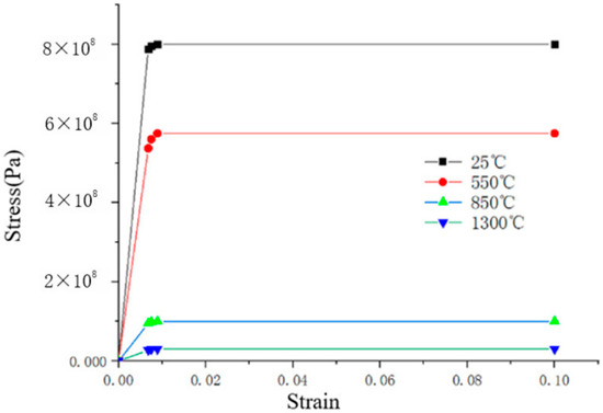
Figure 10.
Stress versus strain plots for Ti80 at different temperatures [30].
A numerical simulation method was employed that combined the element birth and death technique with the prescribed temperature approach. ANSYS2023 Workbench finite element analysis software was used to carry out numerical simulation analysis of residual stresses on this Ti80 butt-welded thick plate (Figure 8) by using thermal sequential coupling, the thermal analysis was carried out using the thermal calculation unit of solid278, and the structural stress analysis model was carried out using the structural stress calculation unit of solid185. The welding residual stress distribution before cutting the Ti80 butt-welded thick plate is shown in Figure 9. The test and simulation results for the welding residual stress before cutting are presented in Figure 6 and Figure 7, respectively. The numerical simulation results were in good agreement with the experimental data, except at the weld centre (Figure 6). This discrepancy occurred because the weld centre is generally uneven, the excess height of the weld centre causes difficulty in focusing the X-ray, and the angle deviation causes stress test distortion [31], so it is difficult to test accurately, due to the relatively short length of the cut specimen along the weld seam. Therefore, in Figure 7, we only use the length of the weld seam on the cut specimen as the transverse coordinates. From Figure 6, Figure 7, Figure 8 and Figure 9, the following can be observed regarding the Ti80 butt-welded thick plate before cutting:
- The weld zone exhibited a significant residual tensile stress concentration, with peak stresses primarily distributed in the regions adjacent to the weld toe. As the distance from the weld toe increased, the residual stress level decreased.
- The transverse residual stress distribution near the weld exhibited an asymmetric bimodal distribution, which was caused by the existence of a welding sequence in the surface weld. The maximum transverse residual tensile stress was approximately 554 MPa, and the longitudinal residual tensile stress was significantly higher than the transverse residual tensile stress.
4. Experimental and Numerical Simulation Studies on the Effect of Wire-Cut Electric Discharge Machining on Welding Residual Stresses
To conduct subsequent mechanical property tests, such as tensile testing, the Ti80 butt-welded thick plate (Figure 8) was cut to form tensile specimens with specific dimensions, as shown in Figure 11. Specific dimensions of cut specimens as shown in Figure 12. The thermal cutting process uses wire-cut electric discharge machining with a cutting speed of 10 mm/min. After cutting, X-ray non-destructive testing was performed on the transverse welding residual stresses at surface measurement points 1–7 (Table 1 and Figure 12). The test results are presented in Table 1 and Figure 6.
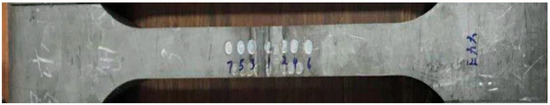
Figure 11.
Cutting specimen model.
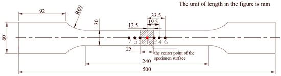
Figure 12.
Specific dimensions of cut specimens (mm).
A numerical simulation of the cutting process was conducted with a relatively efficient simplification based on the thermo-elastoplastic and element birth and death methods. The numerical simulation of the cutting process and the numerical simulation of the welding process are carried out in two stages. After the welding is simulated, the temperature of the Ti80 butt-welded thick plate is cooled to room temperature and then subsequent cutting work is carried out. The simulation interval is 6000 s. The constitutive relationships of Ti alloys undergoing elastic–plastic deformation and material separation criteria during cutting processes are difficult to determine; hence, no cutting tool was introduced in the established finite element model; instead, the cutting process was directly simulated using the element birth and death technology and the specified peak temperature method. The cutting simulation parameters were set to 1300 °C temperature and 10 mm/s cutting speed. The element birth and death technique involves “killing” elements scheduled for removal by multiplying their mass and stiffness matrices by a small number (typically approximately 10−6), while resetting their stress and strain to zero, whereby these elements are excluded from the results to achieve the cutting simulation objectives.
The transverse and longitudinal welding residual stress distributions of the specimens after cutting are shown in Figure 13 and Figure 14, respectively. A certain amount of residual tensile stress remained near the weld on the specimen surface after cutting, whereas the welding residual tensile stress decreased significantly in areas distant from the weld. From Figure 6 and Figure 7, the following can be observed regarding the Ti80 butt-welded thick plate after cutting:
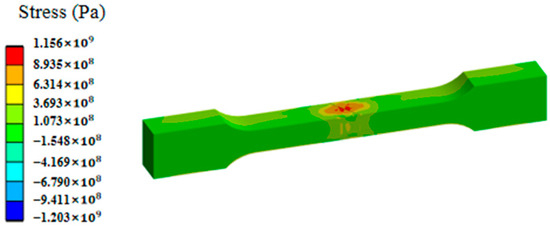
Figure 13.
Transverse residual stress of cut specimen after cutting.
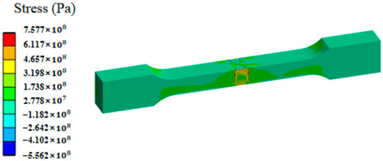
Figure 14.
Longitudinal residual stress of cut specimen after cutting.
- The numerical simulation results for the residual stress are in good agreement with the experimental test results.
- Residual tensile stresses experienced varying degrees of “release”, with the maximum decrease in the transverse welding residual tensile stress reaching approximately 60%. The cutting process had minimal impact on the distribution profile of the transverse residual stresses.
- The maximum reduction in the longitudinal weld residual tensile stress was approximately 36%. As cutting shortened the length direction along the weld from the original 500 mm to 30 mm, the length of the weld was shortened by 94%, and the distribution profile of the longitudinal residual stress changed considerably after cutting.
5. Conclusions
This study employed the thermo-elastoplastic theory and element birth and death method, adopting a combined approach of numerical simulation and experimental testing to calculate and analyse the distribution patterns of residual stresses in Ti80 butt-welded thick plates before and after wire-cut electric discharge machining. The following conclusions were drawn:
- Before wire-cut electric discharge machining, the transverse residual stress distribution near the weld exhibited an asymmetric bimodal profile. Both transverse and longitudinal welding residual stresses were tensile, and the longitudinal residual tensile stress significantly exceeded the transverse residual tensile stress.
- After wire-cut electric discharge machining, varying degrees of “release” occurred in the surface residual tensile stresses. The maximum reduction in the transverse welding residual tensile stress was approximately 60%, whereas the longitudinal welding residual tensile stress exhibited a maximum decrease of approximately 36%.
- The cutting behaviour had minimal effect on the profile of the transverse residual stress distribution perpendicular to the weld direction, whereas it had a greater effect on the longitudinal residual stress along the weld direction.
Wire-cut electric discharge machining processes may modify the residual stresses in Ti alloy butt-welded thick plates, thereby potentially affecting the subsequent evaluation and analysis of the mechanical properties and safety reliability of deep-sea pressure-resistant submersible shells. The results of this study can be applied to the development of large-scale deep-sea pressure-resistant Ti alloy shell structures.
Author Contributions
Conceptualization, Q.W. and L.L.; Data curation, Q.W., C.B. and K.S.; Formal analysis, Q.W.; Funding acquisition, L.L. ; Investigation, L.L.; Methodology, Q.W.; Project administration, L.L.; Validation, Q.W.; Resources, C.B.; Software, Q.W.; Supervision, L.L., C.B. and K.S.; Validation, L.L.; Writing—original draft preparation, Q.W.; Writing—review and editing, Q.W., L.L., C.B. and K.S.; All authors have read and agreed to the published version of the manuscript.
Funding
This work was supported by National Natural Science Foundation of China (52171312).
Data Availability Statement
The original contributions presented in this study are included in the article. Further inquiries can be directed to the corresponding author.
Conflicts of Interest
The authors declare no conflict of interest.
References
- Guo, Y.; Teng, Y.; Liu, G.; Jiao, T. Numerical study on creep-fatigue damage of titanium alloy pressure shell considering the effect of welding residual stresses. Thin-Walled Struct. 2025, 209, 112953. [Google Scholar] [CrossRef]
- Zhang, J.; Liu, H.X.; Chang, M.; Bian, R.G. Numerical simulation and experimental research on the external pressure method for adjusting the welding residual stress of pressure spherical shells. J. Ship Mech. 2018, 22, 1020–1027. [Google Scholar]
- Yu, C.L.; Chen, Z.T.; Chen, C.; Chen, Y.T. Influence of initial imperfections on ultimate strength of spherical shells. Int. J. Nav. Archit. Ocean. Eng. 2017, 9, 473–483. [Google Scholar] [CrossRef]
- Xu, L.; Huang, X.P.; Wang, F. Effect of welding residual stress on the ultimate strength of spherical pressure hull. J. Ship Mech. 2017, 21, 864–872. [Google Scholar]
- Wang, Q.; Fu, X.Y.; Li, Z.L. Generation of residual stresses in rails and their hazards. Heat Treat. Met. 2004, 29, 5. [Google Scholar]
- Arunkumar, M.; Dhinakaran, V.; Sivashanmugam, N.; Petley, V. Effect of Plasma Arc Welding on Residual Stress and Distortion of Thin Titanium Sheet. Mater. Res. 2019, 22, e20190366. [Google Scholar] [CrossRef]
- Liu, C.; Wu, B.; Zhang, J.X. Numerical Investigation of Residual Stress in Thick Titanium Alloy Plate Joined with Electron Beam Welding. Metall. Mater. Trans. B 2010, 41, 1129–1138. [Google Scholar] [CrossRef]
- Kumar, B.; Bag, S.; Amin, M.R. Evaluation of Phase Transformation Strain and Its Influence on Residual Stress Generation in Laser Welded Ti–6Al–4V Alloy. J. Manuf. Sci. Eng. Trans. ASME 2022, 144, 121002. [Google Scholar] [CrossRef]
- Yang, L.; Wang, Y.; Chen, Y. Simulation study on effect of flame cutting speed on temperature field and residual stress distribution. J. Comput. Methods Sci. Eng. 2024, 24, 577–593. [Google Scholar] [CrossRef]
- Dong, P.; Cahill, P.; Yang, Z.; Chen, X.L.; Mattei, N.J. Plate Residual Stress Effects on Dimensional Accuracy in Thermal-Cutting. J. Ship Prod. 2004, 20, 245–255. [Google Scholar] [CrossRef]
- Wang, J.Y.; Kong, B.; Wei, S.L.; Zang, J.; Li, A.H. Simulation Study on Residual Stress Distribution of Machined Surface Layer in Two-Step Cutting of Titanium Alloy. Materials 2024, 17, 4283. [Google Scholar] [CrossRef] [PubMed]
- Yan, P.F.; Wu, Y.X.; Liao, K. Simulation and analysis of effect of cutting machining on residual stress distribution in thick aluminum alloy plate. J. Cent. South Univ. Sci. Technol. 2010, 41, 2213–2217. [Google Scholar]
- Wang, Y.B.; Li, G.Q.; Chen, S.W. Residual stresses in welded flame-cut high strength steel H-sections. J. Constr. Steel Res. 2012, 79, 159–165. [Google Scholar] [CrossRef]
- Dattoma, V.; De Giorgi, M.; Nobile, R. On the evolution of welding residual stress after milling and cutting machining. Comput. Struct. 2006, 84, 1965–1976. [Google Scholar] [CrossRef]
- Liu, C.; Luo, Y.; Yang, M.; Fu, Q. Effects of material hardening model and lumped-pass method on welding residual stress simulation of J-groove weld in nuclear RPV. Eng. Comput. 2016, 33, 1435–1450. [Google Scholar] [CrossRef]
- Liu, C.; Luo, Y.; Yang, M.; Fu, Q. Three-dimensional finite element simulation of welding residual stress in RPV with two J-groove welds. Weld. World Lond. 2017, 61, 151–160. [Google Scholar] [CrossRef]
- Meena, P.; Anant, R. On the interaction to thermal cycle curve and numerous theories of failure criteria for weld-induced residual stresses in AISI304 steel using element birth and death technique. J. Mater. Eng. Perform. 2024, 33, 2279–2297. [Google Scholar] [CrossRef]
- Chen, J.Q.; Shen, W.L.; Yin, Z.X.; Xiao, S.H. Simulation of Welding Temperature Distribution Based on Element Birth and Death. Hot Work. Technol. 2005, 7, 64–65. [Google Scholar]
- Matos, C.G.; Jr, R.H.D. Modeling the effects of residual stresses on defects in welds of steel frame connection. Eng. Struct. 2000, 22, 1103–1120. [Google Scholar] [CrossRef]
- Li, L.B.; Bao, H.N.; Wan, Z.Q.; Li, Y.Q.; Sun, K.X.; Luo, G.E. Influence of residual stress due to the equatorial weld on the ultimate strength of a Ti80 spherical pressure shell. Int. J. Adv. Manuf. Technol. 2021, 116, 1831–1841. [Google Scholar] [CrossRef]
- Wilson, E.L.; Bathe, K.J.; Peterson, F.E. Finite element analysis of linear and non-linear heat transfer. Nucl. Eng. Des. 1974, 29, 110–124. [Google Scholar] [CrossRef]
- Comini, G.; Del Guidice, S.; Lewis, R.W.; Zienkiewicz, O.C. Finite element solution of non-linear heat conduction problems with special reference to phase change. Int. J. Numer. Methods Eng. 1974, 8, 613–624. [Google Scholar] [CrossRef]
- Yuan, F.; Sun, H. Transient temperature fields and residual stress fields of metallic materials under welding. Appl. Math. Mech. 1991, 12, 595–599. [Google Scholar]
- Turner, R.; Ward, R.M.; March, R.; Reed, R.C. The magnitude and origin of residual stress in Ti-6Al-4V linear friction welds: An investigation by validated numerical modeling. Metall. Mater. Trans. B 2012, 43, 186–197. [Google Scholar] [CrossRef]
- Steinzig, M.; Takahashi, T. Residual stress measurement using the hole drilling method and laser speckle interferometrypart Ⅳ: Measurement accuracy. Exp. Tech. 2003, 27, 59–63. [Google Scholar] [CrossRef]
- Li, X.W.; Liu, J.W.; Wu, H.; Miao, K.S.; Wu, H.; Li, R.G.; Liu, C.L. Research progress of residual stress measurement methods. Heliyon. 2024, 10, e28348. [Google Scholar] [CrossRef]
- GB/T 7704-2017; Non-Destructive Testing X-Ray Stress Measurement Method. Standardization Administration of the People’s Republic of China: Beijing, China, 2017.
- Peng, H.E.; Wu, Y.; Zhang, T.; Chen, S.Y.; Zhang, C. Residual stresses in linear friction welding of TC17 titanium alloy considering phase fraction. Trans. Nonferrous Met. Soc. China 2024, 34, 184–193. [Google Scholar]
- Shi, C.; Zhong, Q.; Li, C. China Materials Engineering Canon; Chemical Industry Press: Beijing, China, 2006. [Google Scholar]
- Wang, Y.X.; Guo, J.T.; Zhang, B.W.; Ge, K.K.; Li, L.B.; Lv, F. Effect of Residual Stress on the Ultimate Bearing Capacity of Titanium Alloy Pressure Spherical–Cylindrical-Combined Shells. Metals 2024, 14, 123. [Google Scholar] [CrossRef]
- Withers, P.J.; Bhadeshia, H.K.D.K. Residual stress Part 1-Measurement techniques. Met. Sci. J. 2001, 17, 355–365. [Google Scholar] [CrossRef]
Disclaimer/Publisher’s Note: The statements, opinions and data contained in all publications are solely those of the individual author(s) and contributor(s) and not of MDPI and/or the editor(s). MDPI and/or the editor(s) disclaim responsibility for any injury to people or property resulting from any ideas, methods, instructions or products referred to in the content. |
© 2025 by the authors. Licensee MDPI, Basel, Switzerland. This article is an open access article distributed under the terms and conditions of the Creative Commons Attribution (CC BY) license (https://creativecommons.org/licenses/by/4.0/).