1. Introduction
The primary use of ferrochrome (85%) is in the production of stainless steel [
1]. Stainless steel is used in the manufacture of household goods, kitchen surfaces, and equipment related to food production. According to [
2], the flow patterns and in-use stocks of chromium in China’s stainless steel production chain from 2012 to 2022 show significant trends. During this period, chromium consumption in China increased substantially, with annual growth rates exceeding 10%, and 90.4% of the chromium was imported. It can be assumed that the demand for chromium will continue to grow in the future. As chromium consumption increases, the production of chromium slags is also expected to rise since these are by-products of chromium extraction and refining processes.
Global ferrochrome slag production ranges between 12 and 16 million tons annually [
3].
Depending on the ferrochrome production technology, several types of slag can be generated. Typically, slags are classified into the following categories: high-carbon grades containing 5–8% carbon, medium-carbon grades with 1–4% carbon, and low-carbon (LC) grades containing 0.1–0.5% carbon. The formation of mineral phases in ferrochrome slag systems primarily depends on the slag’s chemical composition, as well as the cooling rate or solidification scheme. Additionally, the slag composition is influenced by factors such as ore type, fluxing methods, partial oxygen pressure, reduction temperature, and the residence time of slag in the high-temperature zone of the furnace [
4].
Chromium ores used for smelting refined ferrochrome should also contain a minimum amount of silica, which will reduce the consumption of lime, decrease the chromium content of the slag (loss), and increase SiO
2 in the slag. The main amount of low-carbon ferrochrome is produced by silicothermic reduction in chromium oxides using ferrosilicochromium in the presence of lime as flux. The reduction in chromium proceeds through Cr
2O
3 → CrO → Cr. During smelting, other oxides (e.g., silicon, calcium, magnesium, phosphorus, and sulfur) may react to form compounds that enter either the metal or the slag phase, depending on thermodynamic conditions. At the same time, the reduction in oxides of Cr, Si, Ca, Mg, P, S, etc., occurs in the furnace, as evidenced by the presence of these elements in the alloy. Smelting is normally a two-step process: first, only one part of the raw materials (chromite ore, lime, FeSiCr) is loaded into the furnace. After melting that first part, the second part of FeSiCr, chromite ore, and lime are added. As soon as the melting process is completed, metal and slag will be released [
5]. The temperature of the slag is 1800 °C, and the temperature of the metal is 1760 °C [
6]. The dominant phase in low-carbon chromium slag is γ-dicalcium silicate (γ-C
2S). The main reason for the self-pulverization of refined slag is the polymorphism of the dicalcium silicate; it attains a dusty state during the cooling process after removal from the furnace. When cooled from high temperatures, α-C
2S converts to β-C
2S at 630 °C degrees, then to γ-C
2S at lower temperatures [
7]. Thus, the crumbling feature is caused by the spatial redistribution of close-packed oxygen ions due to changes in ion polarization under the influence of temperature. (N.B. This is the reason why ordinary Portland cement also crumbles.)
Ferrochrome producers in Finland, Sweden, and Russia efficiently utilize these slags in road construction and the production of building materials. In South Africa, ferrochrome slags are safely disposed of in landfills. Due to their excellent combination of high strength and refractory phases, ferrochrome slags can be processed in various ways, including use in road construction, building materials, refractory products, or simply landfilling [
8] (
Figure 1).
Refined ferrochrome slags are mainly used in the cement industry. However, their application is limited due to the presence of free magnesium oxide and residual chromium oxides, which remain in the mineralogical structure of the slag due to the incomplete reduction in chromium during smelting. These components are strictly regulated by cement industry standards [
9].
The depletion of traditional mineral raw materials, combined with the accumulation of industrial waste in long-established metallurgical regions, is having an increasingly harmful impact on both the natural environment and the economic viability of production processes. As natural resources become more scarce, the extraction of new raw materials becomes more expensive and environmentally damaging. At the same time, the waste generated in these industries—such as slags—continues to accumulate, creating environmental threats, especially when not properly managed.
In response to these challenges, interest is growing in exploring the potential of slags as a secondary mineral resource. Slag, a by-product of metallurgical processes, often contains valuable metals and minerals that can be recycled or reused. By finding sustainable methods for slag processing, industries can reduce their dependence on primary raw materials, lessen environmental pressures, and lower production costs. This approach not only facilitates more efficient waste management but also supports the concept of a circular economy—transforming what was previously considered waste into a valuable resource, thereby contributing to more sustainable industrial practices.
For example, ferrochrome dust was used as a partial replacement for conventional silicate in concrete production. Optimal performance was achieved when 40 wt.% of ferrochrome dust and 7 wt.% of lime replaced 47 wt.% of the standard silicate component. Toxicity testing through the TCLP method indicated that the concrete posed no environmental hazards. Therefore, ferrochrome dust presents a sustainable and eco-friendly option for concrete manufacturing [
10].
In the study [
11], a novel approach was investigated for extracting chromium units from ferrochrome baghouse dust (FeCr BFD) and the ultrafine slag fraction (UFS) using ozonation in an aqueous medium and advanced oxidation processes. The results showed that ozonation in water achieves only limited chromium release from the waste materials. For BFD, the maximum chromium release reached 4.2% of the total content. However, chromium release from BFD was significantly higher compared with the ultrafine slag (UFS), which was attributed to differences in the characteristics of these two materials.
Study [
12] examined magnetic and gravity separation methods for concentrating chromium in chromium-containing slags generated during the production of stainless steel (SS) and ferrochrome (FeCr). The results of this research clearly demonstrate the potential of these beneficiation methods for processing SS and high-carbon (HC) FeCr slags. For SS slag, the Wet High Intensity Magnetic Separation (WHIMS) method enabled an increase in chromium concentration to nearly 9 wt.% Cr. Although this chromium content is still too low for ferrochrome production, it may serve as a preliminary step before hydrometallurgical chromium extraction.
The effective separation of iron-bearing components from steel slag using magnetic separation was investigated in [
13]. It was concluded that achieving a concentrate with optimal total iron content via dry magnetic separation is a complex task. Therefore, steel slag should undergo multi-stage wet low-intensity magnetic separation with an optimal magnetic intensity of 100 mT.
Magnetic separation is ineffective for recovering iron from fine steel slag particles at magnetic field strengths above 1000 G. Effective separation occurs at fields below 1000 G, particularly in the range of 200 to 800 G. Although lower magnetic field strength increases the iron content in the concentrate, maintaining higher magnetic field strength in drum magnetic separators is necessary to ensure sufficient product yield [
14].
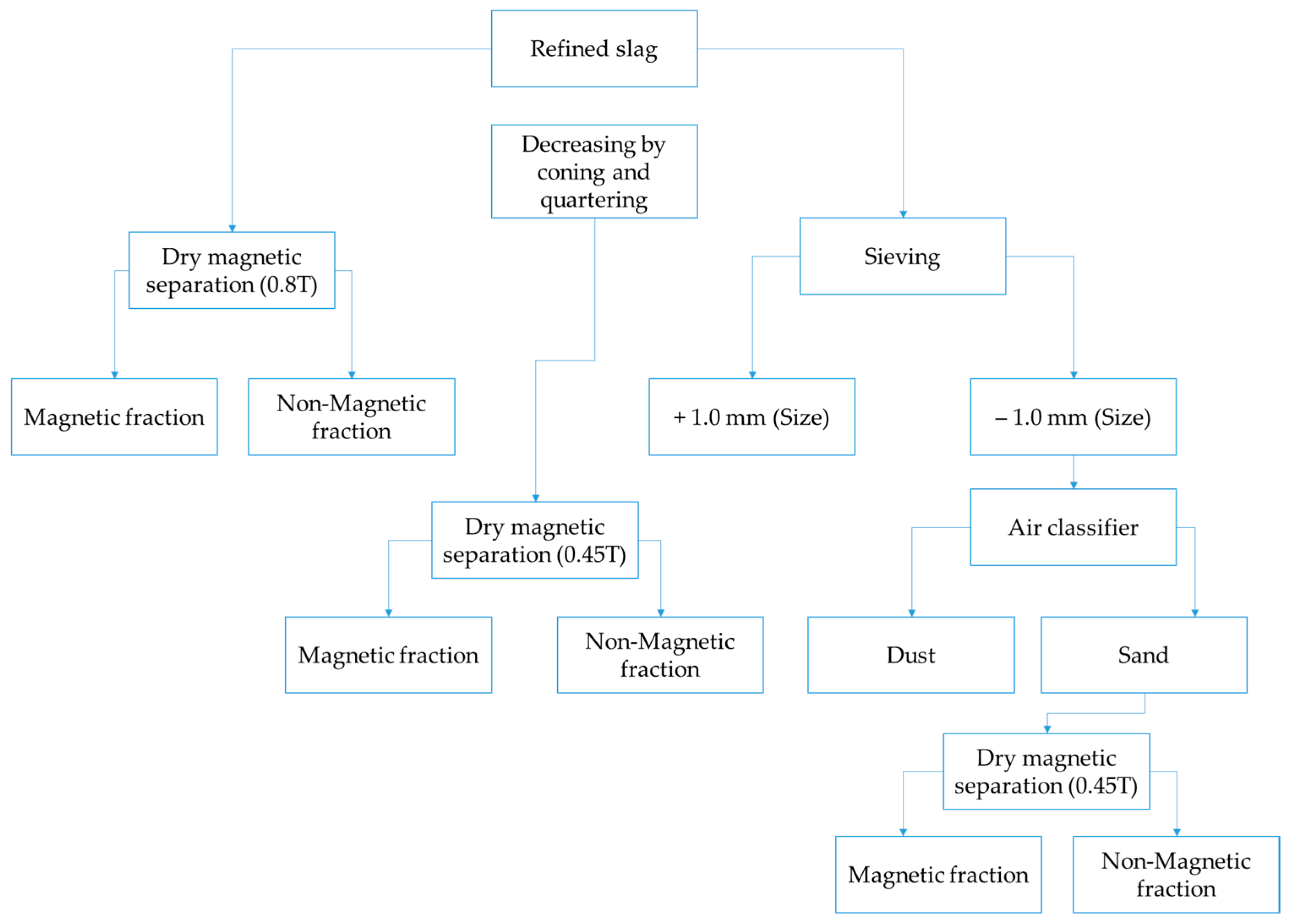
This study focuses on the effectiveness of dry magnetic separation for the recovery of metallic chromium (Crmet) from refined ferrochrome slag, with the aim of quantitatively evaluating the possible recovery rate.
2. Materials and Methods
For this study, we used 48 kg of refined ferrochrome slag. Since the slag sample primarily consists of fine-grained material, no preliminary treatment such as crushing, grinding, milling, or screening was required.
Various methods were employed to characterize and analyze the waste, including particle size distribution, chemical composition, surface chemical composition, and crystalline phase analysis.
Dry sieving was used to determine the particle size distribution of the slag. Microscopic evaluation was performed using a stereomicroscope for detailed microscopic characterization. X-ray powder diffraction analysis (XRD) was applied for phase identification. Additionally, X-ray fluorescence spectrometry (XRF) was used to determine the elemental chemical composition of the sample.
The sample for sieving was homogenized and reduced using the cone and quartering method. The density of the samples was determined according to the LST EN 15103-20107 [
15] method using a glass pycnometer. The measured density was 2778 kg/m
3.
The bulk density of the sample was determined according to the accredited standard method EN 1236-2013 [
16]. The bulk density of the material was as follows:
- -
In a moist state: 1236.1 kg/m3;
- -
In a dry state: 1122.8 kg/m3.
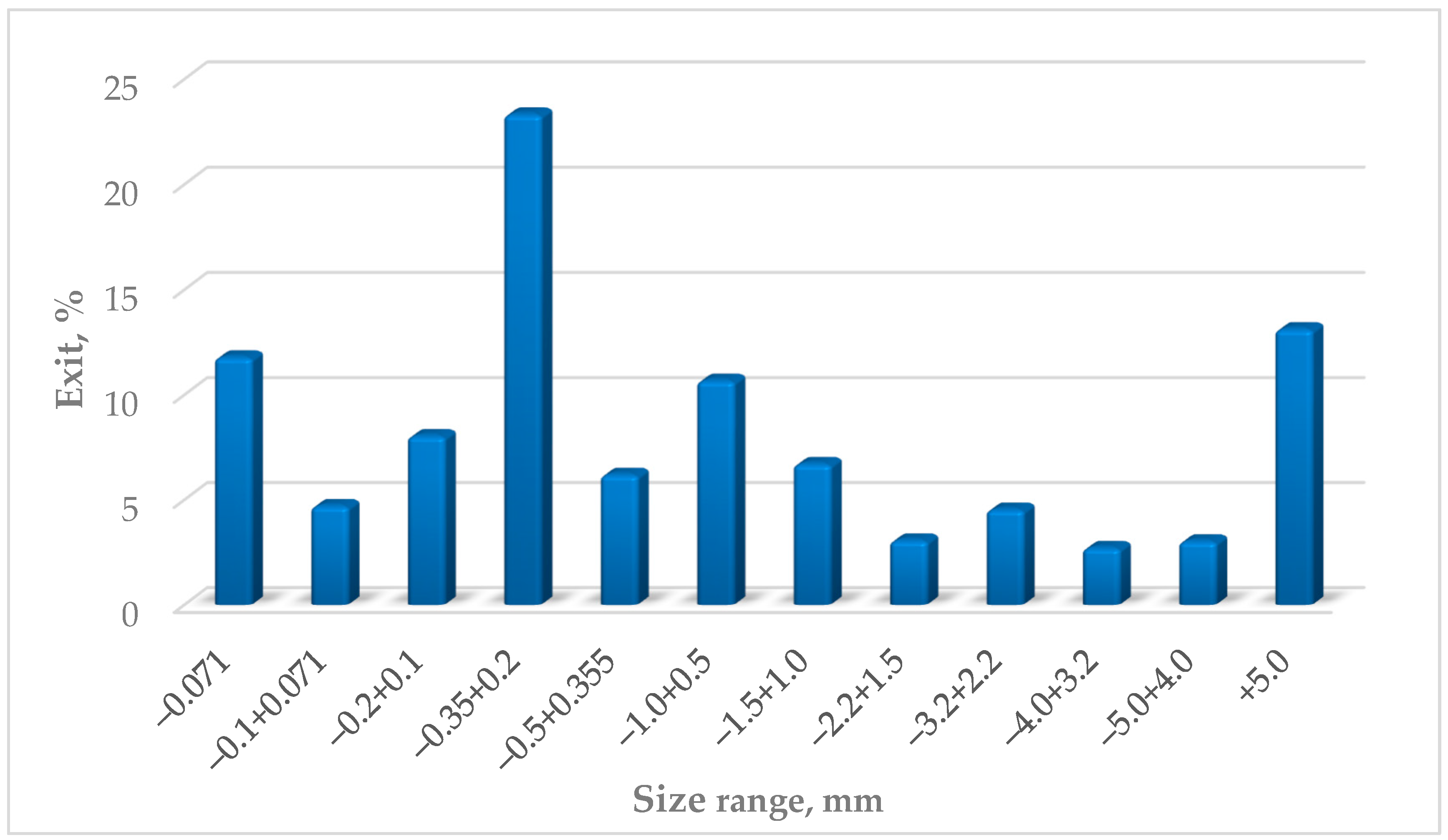
The particle size distribution was determined according to the accredited standard method SRPS ISO 2591-1:1992 [
17], using laboratory test sieves made of woven wire cloth and perforated metal plate (
Figure 2).
Most of the product appears as a light gray powder, predominantly in the form of aggregated lumps. These lumps easily crumble with minimal effort, turning into a loose powder. Larger grains mainly consist of clusters of small particles of different colors bound together by a grayish powder.
According to the X-ray powder diffraction (XRD) analysis (
Figure 3,
Table 1), the dominant crystalline phase in the sample is γ-dicalcium silicate (C
2S), indicating a high content of calcium and silicon in the matrix. In addition to γ-C
2S, periclase (MgO) and monticellite—likely iron-substituted and corresponding to the olivine group mineral Ca(Mg,Fe)SiO
4 with an orthorhombic structure—were also identified.
With regard to chromium- and iron-bearing phases, two were clearly detected the following:
- -
Magnesiochromite ((Mg,Fe2+)(Cr,Al)2O4), a spinel phase, with the majority of its characteristic peaks present in the diffractogram.
- -
Ferrochrome alloy (CrFe), identified by its most intense diffraction peak at d = 2.03 Å, indicating the presence of residual metallic inclusions.
Complementary compositional analysis was performed using wavelength dispersive X-ray fluorescence (WD-XRF). The oxide composition revealed that CaO and SiO2 dominate, together comprising approximately 60–65 wt.% of the sample. MgO (~8 wt.%) and Al2O3 (~3 wt.%) are present as secondary constituents. The total chromium content is approximately 4 wt.%, while iron occurs at lower levels, indicating that chromium is more strongly retained in the residual mineral phases.
Based on XRD and complementary mineralogical analysis (including optical and SEM-EDS), the following phases were identified in the sample:
- -
Portlandite, as a hydration product of lime;
- -
Silicate minerals, including members of the olivine, pyroxene, and amphibole groups;
- -
Spinel-group minerals, including both natural and secondary chromite and magnesiochromite;
- -
During solidification, various microstructural features were observed, including garnet minerals, eutectic structures, and sulfide inclusions (e.g., pyrrhotite);
- -
Limonite, indicative of post-solidification oxidation and weathering;
- -
Discrete metallic particles representing residual ferrochrome.
The metallic phase content in the sample is estimated to be 2–3 wt.%. It occurs partly as free, rounded particles (beads, spheres) and partly as finely disseminated inclusions encapsulated within silicate matrices, which limits liberation during mechanical processing. Spinel-group minerals were identified as complex solid solutions formed during high-temperature processing.
Given the high proportion of calcium silicate phases, as well as the presence of portlandite, the material—after metallic phase recovery—may be considered as a potential secondary raw material for cement production, pending leaching and mechanical stability evaluations. The portion of the metallic phase embedded in the silicate matrix as mineral chromite is not suitable for magnetic separation.
Considering the grain size fraction found and the natural need to increase recovery of valuable components (freeing the metallic phase included in silicate minerals), the expected usability of metal in the magnetic fraction cannot be high. In other words, low recovery is expected, with a significant portion of metal remaining in the non-magnetic fraction, i.e., in the tails.
3. Results and Discussion
The obtained results of magnetic separation are presented in
Table 2.
A comparison of the results obtained for dry magnetic separation at different field strengths shows that separation at 0.45 T is more effective for producing cleaner tailings. Specifically, at 0.45 T, the tailings account for approximately 46% of the feed and contain only 0.87% (1.2%) of metallic chromium, indicating a high level of impurity removal. In contrast, tailings obtained at 0.8 T contain significantly higher levels of metallic and total chromium (6.10% and 3.60%, respectively), which contradicts the theoretical expectation of magnetic separation efficiency. According to magnetic separation theory, increasing the magnetic field strength should enhance the recovery of magnetic particles, resulting in less metal content in the tailings. However, the observed results may be attributed to the heterogeneous nature of metallic inclusions in the slag, where some particles are rich in chromium and others in iron. At higher field strength, Fe-rich particles are more readily captured by the magnet, while Cr-rich particles with lower magnetic susceptibility may remain in the tailings. This explains why increasing field strength does not lead to a proportional increase in chromium recovery. Considering that the primary goal of the preliminary separation stage is to isolate as many final tailings as possible and reduce the load on subsequent processing stages, the use of dry magnetic separation at 0.45 T is considered optimal for this purpose.
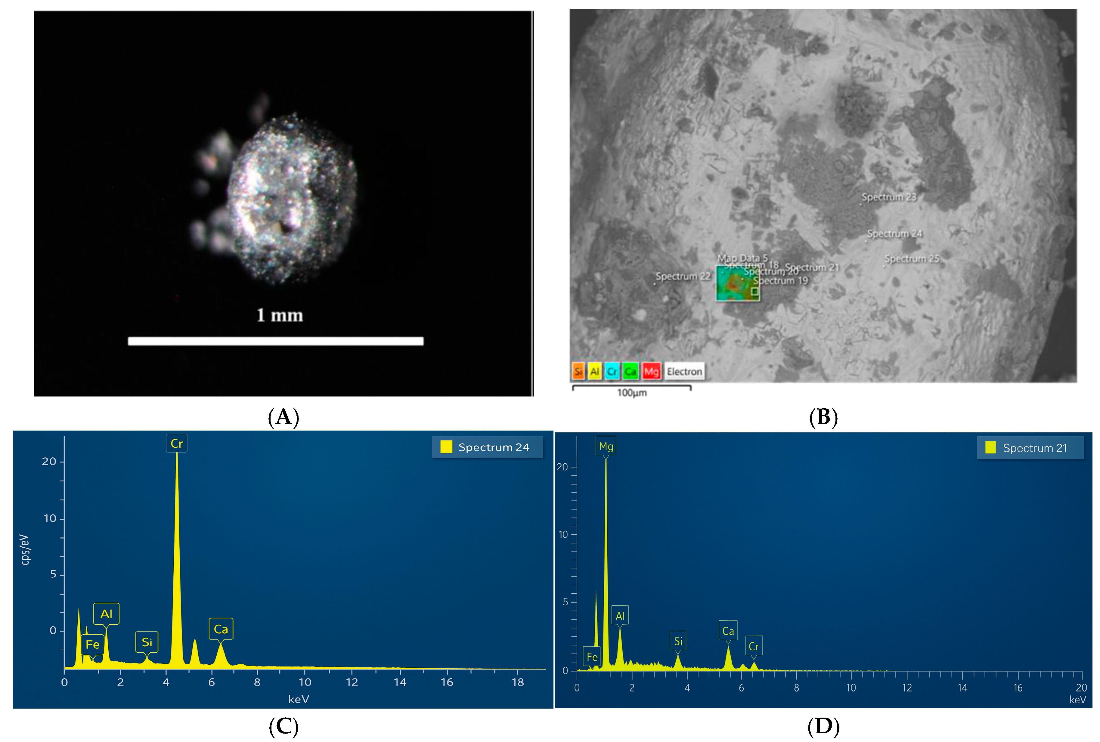
Figure 8 shows a metallic bead grain with a heterogeneous phase composition. The SEM-BSE image (
Figure 8B) reveals that the grain has a chromium-rich matrix, presumably representing a metallic alloy. SEM-EDX analysis identified dark gray areas on the grain surface, morphologically resembling cubic structures composed of magnesium and oxygen (Mg–O). SEM-EDX also revealed lighter gray regions whose chemical composition (Ca–Si–O) indicates the presence of calcium silicate.
In slag, CrFe typically contains about 0.6–2.2% of metallic inclusions and beads [
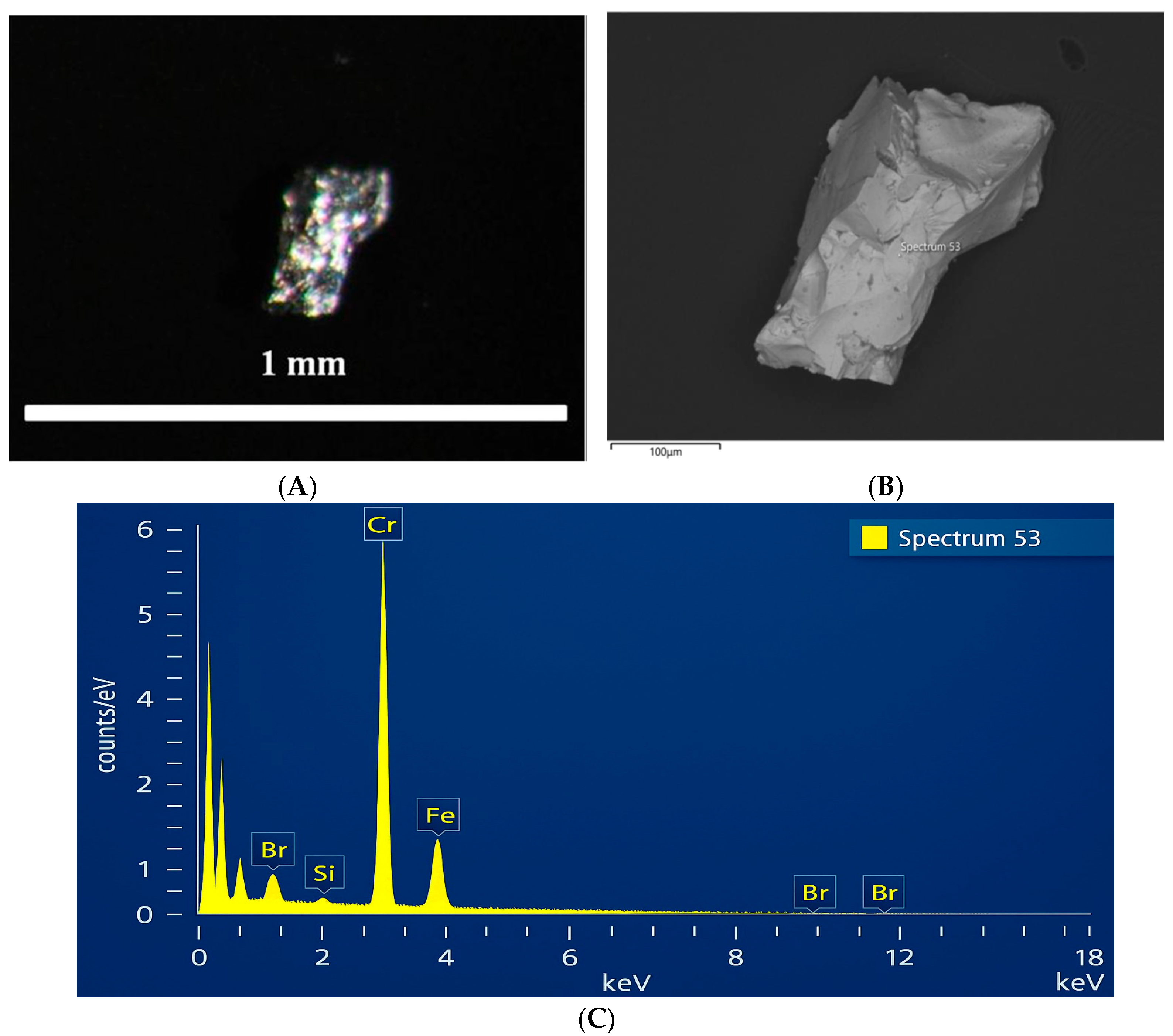
5], presumably representing a reduced CrFe alloy. For a more detailed study of the magnetic grains, manual selection was carried out. A representative example is shown in
Figure 9A, where an alloy grain is presented. The SEM-BSE image (
Figure 9B) displays a homogeneous matrix with a smooth surface, and the SEM-EDX spectrum (
Figure 9C) shows that the composition consists of chromium and iron (Cr–Fe).
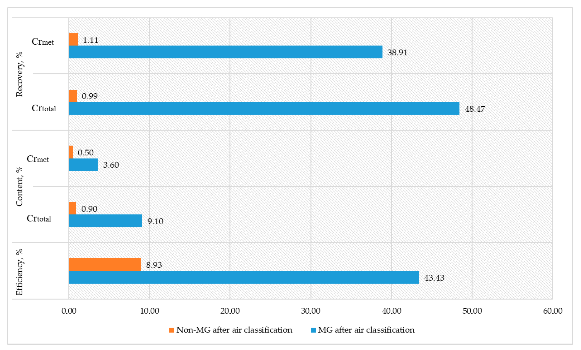
In the second stage of the experiment, the initial material was screened through a sieve with a mesh size of 1 mm prior to air classification. The sand fraction obtained after air classification was subjected to magnetic separation at a magnetic field intensity of 0.55 T. The results of the experiment are presented in
Figure 10.
Application of Magnetic Separation to Sand Fractions
Magnetic separation of the sand fractions allowed for the recovery of a magnetic fraction containing 3.6% metallic chromium (Crmet), accounting for 83% of the original sand mass, and a non-magnetic fraction with 0.5% Crmet, comprising 17%.
The metallic fraction (MF) obtained after air classification demonstrated a separation efficiency of 43.43%, although it had slightly lower values of total chromium (Cr
total—9.10%) and metallic chromium (Cr
met—7.70%) compared with the coarser +1 mm fraction (48.47% Cr
total and 49.45% Cr
met). This indicates that air classification influenced the chromium distribution, likely due to particle size separation, which is supported by data from a scientific study [
18].
The non-metallic fraction (non-MF) obtained after air classification exhibited significantly lower efficiency (8.93%) and Crmet content (0.50%), indicating a predominance of non-metallic or low-chromium materials. Recovery values for this fraction were also minimal (1.11% for Crmet), confirming that the majority of valuable chromium remained in the metallic fractions.
The dust fraction constituted a small portion of the total material (4.27%) with relatively low Crtotal (3.70%) and Crmet (0.70%) contents. Low chromium recovery values (1.94% for Crtotal and 0.74% for Crmet) indicate minimal chromium loss via dust, though this fraction still warrants further investigation. Additional analysis of this fraction could assess the potential for fine material recovery and improve overall chromium utilization.
The study demonstrated that the applied method of dry gravity concentration is effective for enriching the supplied samples of chromium-containing slag.
This segment of the research on slag sample enrichment by pneumatic separation using the “SEPAIR” technology was conducted on size-classified fractions of 0–1 mm, 1–3 mm, 3–6 mm, and a wide size range of 0–20 mm. The Cr content in the initial samples ranged from 1.34% to 1.71%. The qualitative and quantitative parameters of the obtained concentrates, depending on the enrichment depth, are presented in
Table 3.
Based on the comparison of the data in this table, it can be concluded that good results were achieved for all particle size classes, regardless of the separation depth.
Nevertheless, the most efficient enrichment was observed when processing the wide particle size class. This is due to the fact that during separate classification, materials larger than 6 mm were not involved in the enrichment process. Re-cleaning Product No. 1 (dust 0–1.0 mm) and undersize 0–1.6 mm on a separator for fine fractions can increase recovery up to 69% or more.
The high efficiency of enrichment using the wide particle size class without prior size classification is attributed to the significant density difference between the slag particles and the metallic droplets. This is a clear advantage, as industrial-scale enrichment would not require a separate separator for each size class.
The industrial products obtained from enrichment, with chromium content ranging from 1.8% to 5.5%, can be subjected to re-cleaning for additional chromium recovery after further crushing.
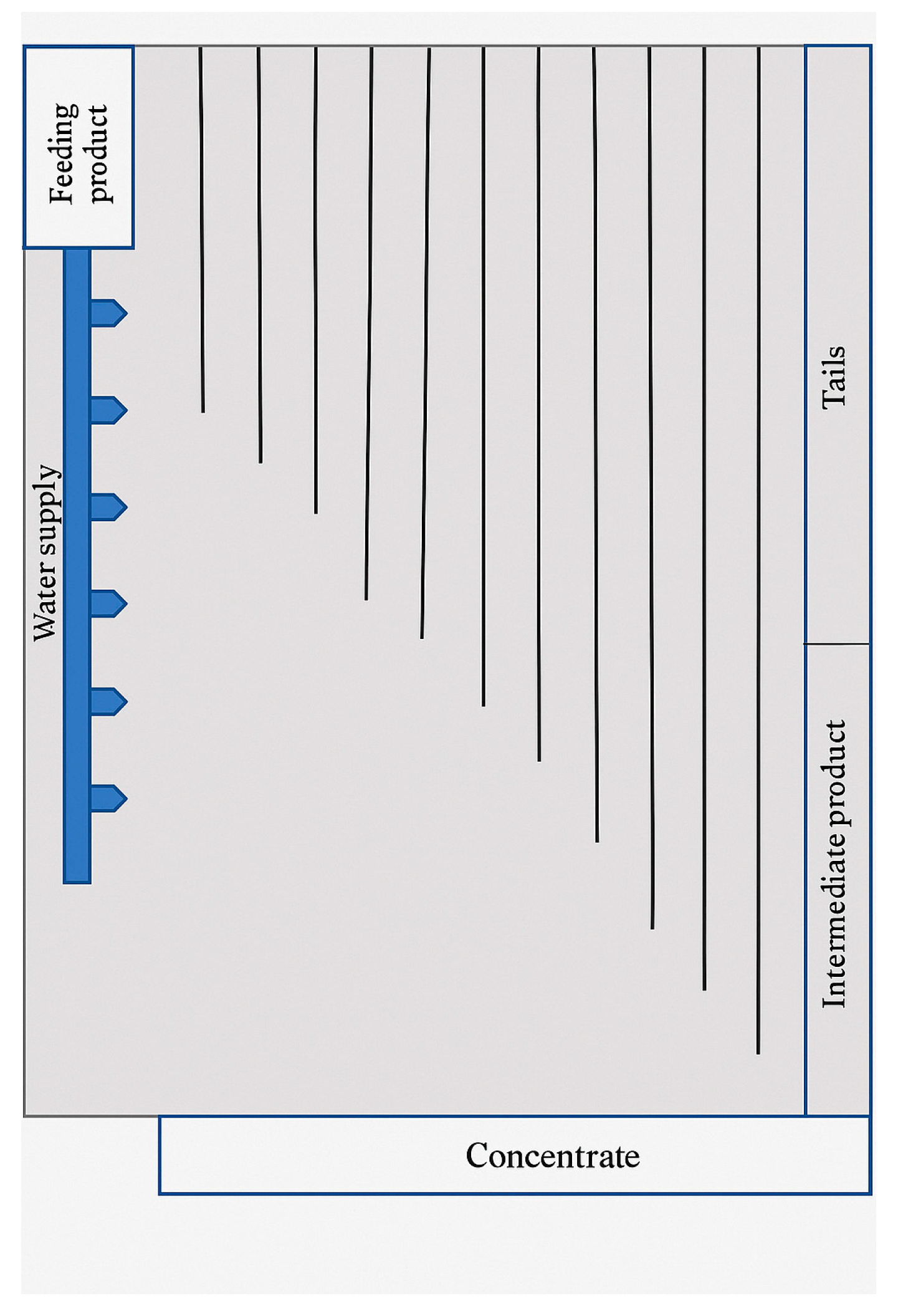
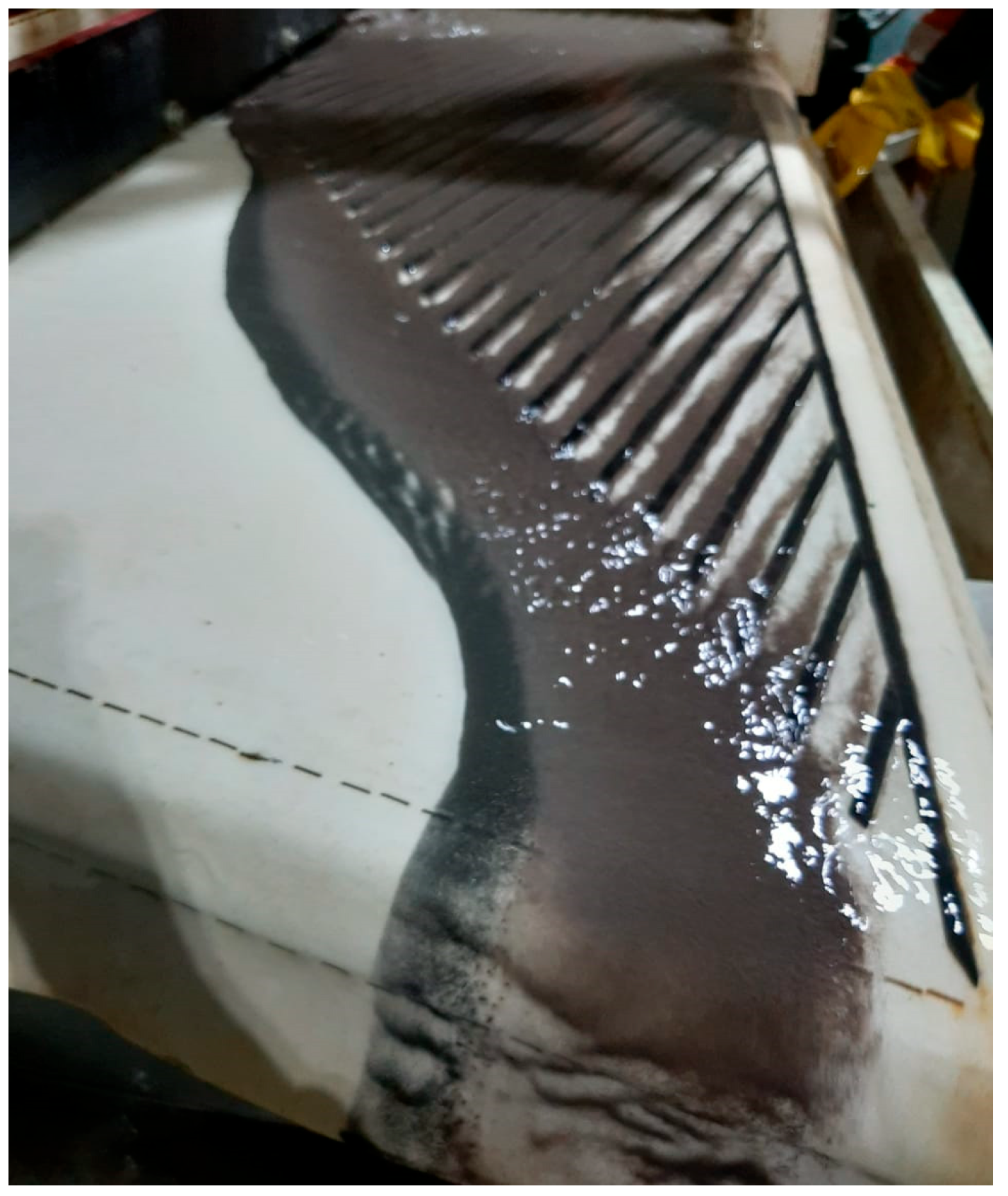
Enrichment of refined ferrochrome slag using a shaking table effectively separated the chromium-containing fraction as a concentrate. Despite the small mass yield of the concentrate (only 3.8% of the total mass), its chromium content was high—29.9%, ensuring a 90.7% total chromium recovery. This indicates the high selectivity of the separation by density and particle size. Such a result is especially valuable in waste processing, where minimizing the loss of valuable components is crucial.
The main portion of the material (93.2%) was discarded as tailings with a very low chromium content—0.2%. Their contribution to total recovery was only 8.1%, confirming the effective concentration of the valuable phase in the heavy fraction. The intermediate product, accounting for 3.1% of the mass, had a chromium content of 0.4% and an insignificant contribution to recovery—1.2% (
Table 4).
Figure 11 visually illustrates the separation of products on the shaking table, confirming the high-quality sorting of the material.
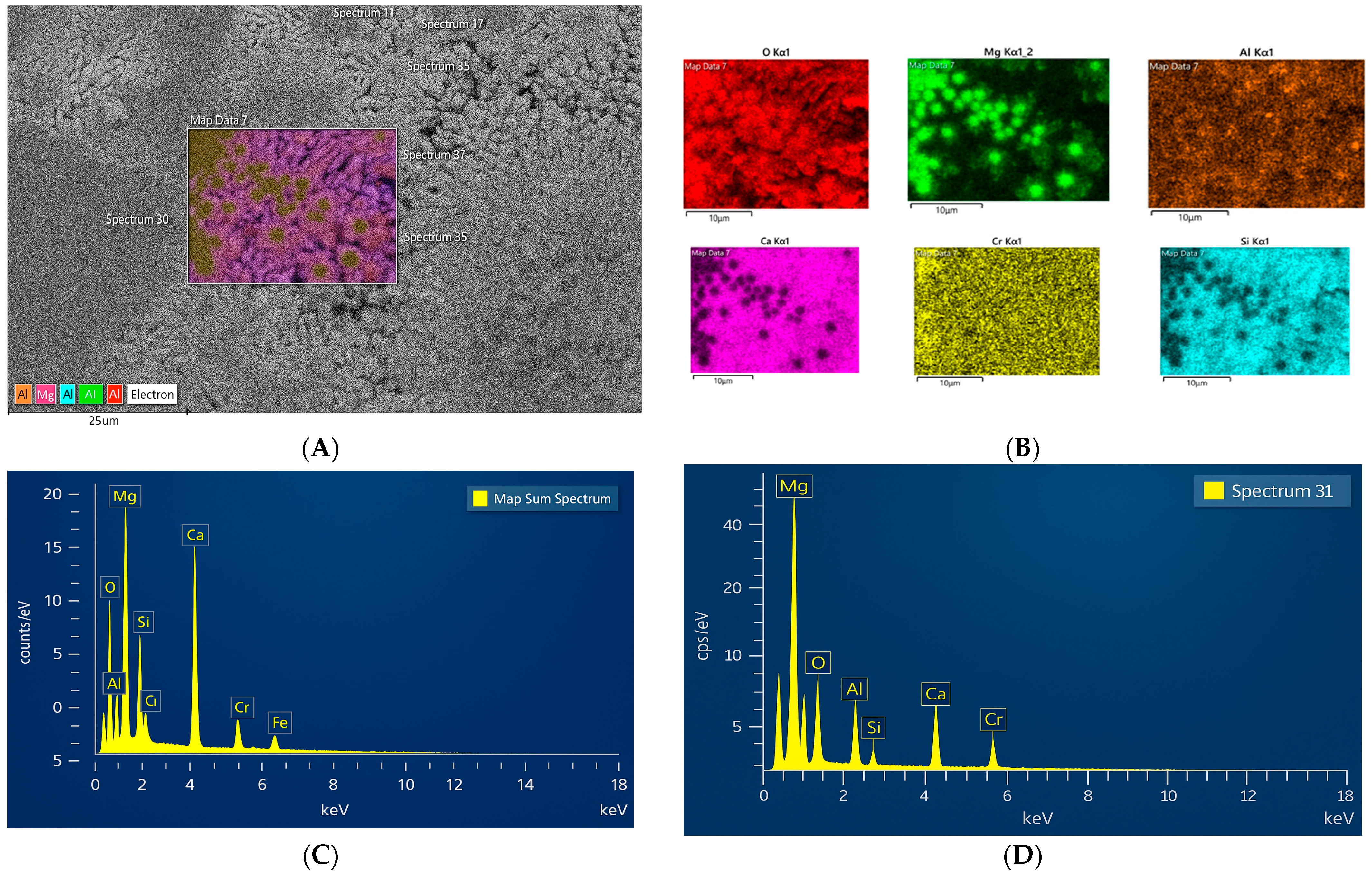
The concentrate obtained on the concentration table contained several green, spherical grains with an uneven surface texture. At high magnification under SEM-BSE, a heterogeneous matrix was revealed, with black spots surrounded by a lighter pattern (
Figure 12). A bright gray pattern of various shapes is observed: some are rounded, while others are elongated. The black cubic-shaped spots are enriched with magnesium (
Figure 12D). This phase may correspond to periclase (MgO), which is supported by XRD analysis results. Elemental mapping analysis (
Figure 12B) shows that the gray areas consist of Ca-Si-O, presumably dicalcium silicate (Ca
2SiO
4), which was identified in the XRD analysis. Between them, a small transition zone of Ca-Mg silicate is assumed.
4. Conclusions
The results of both magnetic separation and pneumatic classification highlight the effectiveness of different separation methods for concentrating chromium (Cr).
Magnetic separation: At a magnetic field intensity of 0.8 T, most of the material (72.40%) passes into the magnetic fraction, but the distribution of metallic chromium (Crmet) between the magnetic and non-magnetic fractions is almost equal, which reduces the efficiency of extracting metallic chromium. At 0.45 T, although less material (54.01%) enters the magnetic fraction, the Crmet content is significantly higher (6.70%), and the extraction of Crmet reaches a much higher level—90.05%.
According to these results, the 0.45 T mode is more effective for selective concentration of metallic chromium, while 0.8 T captures more total material but with lower selectivity.
Combination of pneumatic classification and magnetic separation: This can optimize chromium recovery. Pneumatic classification effectively concentrates chromium in the metallic fraction, while magnetic separation at 0.45 T is especially efficient for the selective extraction of metallic chromium.
Pneumatic separation using the “SEPAIR” technology: This method demonstrated high efficiency in enriching chromium-containing slags, especially when processing a wide size fraction (0–20 mm), which allowed chromium recovery up to 40.32%. This is due to the involvement of larger particles in the process, thanks to the significant difference in densities between slag grains and metallic particles. Also, using a single separator for a wide fraction reduces costs and simplifies the technological process.
Enrichment on a concentration table: The process showed high selectivity, producing a concentrate with a chromium content of 29.9% and a recovery of 90.7%. Despite the low concentrate yield (only 3.8% of the total mass), the process effectively separated the chromium-containing fraction, minimizing losses of valuable components. Such results confirm the high efficiency of both methods for slag processing, contributing to improved final product quality and overall profitability.
Comparison of methods: The highest chromium content concentrate can be obtained via processing on the concentration table, although the yield is low. Dry magnetic separation at 0.45 T provided 72.85% product extraction as magnetic particles with a total chromium content of 11% and an efficiency of 54.01%.
Based on the studies of mechanical, mineralogical, and chemical properties of the raw material—slag—as well as laboratory testing of various enrichment methods, the following conclusions can be made:
- -
Magnetic separation/enrichment methods, due to their low extraction and enrichment degrees, can be applied as primary processing methods.
- -
Pneumatic separation shows satisfactory results, and the concentrates obtained can already be economically justified as feedstock for remelting and production of commercial ferrochrome.
- -
Enrichment on concentration tables allows for maximum extraction of the valuable component as concentrates are suitable for remelting and for direct use after briquetting.
The tails obtained can be used as raw material for producing shaped construction products subjected to autoclave carbonation with carbon dioxide [
19].
Author Contributions
Conceptualization, O.S. and M.D.; methodology, B.K. and A.A.; software, A.A. and B.K.; validation, D.Y., A.D. and A.A.; formal analysis, A.D. and M.D.; investigation, A.D. and D.Y.; resources, A.D.; data curation, A.A.; writing—original draft preparation, O.S. and L.T.; writing—review and editing, O.S., B.K., D.Y. and L.T.; visualization, A.A.; supervision, A.D.; project administration, O.S.; funding acquisition, O.S. All authors have read and agreed to the published version of the manuscript.
Funding
This research is funded by the Science Committee of the Ministry of Science and Higher Education of the Republic of Kazakhstan (Grant No. AR 19577218).
Data Availability Statement
The original contributions presented in this study are included in the article. Further inquiries can be directed to the corresponding authors.
Acknowledgments
The authors declare that no generative AI tools were used for text generation, data analysis, or any part of the study design or manuscript preparation.
Conflicts of Interest
The funders had no role in the design of the study; in the collection, analyses, or interpretation of data; in the writing of the manuscript; or in the decision to publish the results.
References
- Cunat, P. Alloying Elements in Stainless Steel and Other Chromium-Containing Alloys; International Chromium Development Association: Paris, France, 2004; pp. 1–24. Available online: http://scholar.google.com/scholar?hl=en&btnG=Search&q=intitle:Alloying+Elements+in+Stainless+Steel+and+Other+Chromium-Containing+Alloys (accessed on 25 January 2025).
- Yang, L.; Liu, J.; Hua, X.; Wang, H. Mapping Chromium Flows in China’s Stainless-Steel Product Chain: A Product-Level Substance Flow Analysis. Resour. Conserv. Recycl. 2024, 209, 107816. [Google Scholar] [CrossRef]
- Richard, P. Overview of the Global Chrome Market. In Proceedings of the INDINOX Stainless Steel Conference-1, Ahmedabad, India, 25–26 January 2015. [Google Scholar]
- Hayes, P.C. Aspects of SAF Smelting of Ferrochrome. In Proceedings of the Tenth International Ferroalloys Congress, Cape Town, South Africa, 1–4 February 2004; pp. 1–14. [Google Scholar]
- Gasik, M.I. Technology of Chromium and Its Ferroalloys. In Handbook of Ferroalloys, 12th ed.; Elsevier: Amsterdam, The Netherlands, 2013. [Google Scholar] [CrossRef]
- Ryss, I. *Recovery Methods for Metallurgical Slags*; Metallurgy Press: Moscow, Russia, 1985. (In Russian) [Google Scholar]
- Chang, Q.; Smith, J.; Liu, H. Investigation of Chromium Recovery Techniques from Ferrochrome Slag. Metall. Mater. Trans. 2016, 47, 1234–1245. [Google Scholar]
- Sahu, N.; Biswas, A.; Kapure, G.U. A Short Review on Utilization of Ferrochromium Slag. Miner. Process. Extr. Metall. Rev. 2016, 37, 211–219. [Google Scholar] [CrossRef]
- Sariyev, O.R.; Musabekov, Z.B.; Dossekenov, M.S. Disposal of Slag of Refined Ferrochromium by Obtaining a Sintered and Carbonized Construction Products. Kompleks. Ispolz. Miner. Syra = Complex Use Miner. Resour. 2019, 4, 26–34. [Google Scholar] [CrossRef]
- Acharya, P.K.; Patro, S.K. Use of Ferrochrome Ash (FCA) and Lime Dust in Concrete Preparation. J. Clean. Prod. 2016, 131, 237–246. [Google Scholar] [CrossRef]
- Van Staden, Y.; Beukes, J.P.; Van Zyl, P.G.; Du Toit, J.S.; Dawson, N.F. Characterisation and Liberation of Chromium from Fine Ferrochrome Waste Materials. Miner. Eng. 2014, 56, 112–120. [Google Scholar] [CrossRef]
- Kukurugya, F.; Nielsen, P.; Horckmans, L. Up-Concentration of Chromium in Stainless Steel Slag and Ferrochromium Slags by Magnetic and Gravity Separation. Minerals 2020, 10, 906. [Google Scholar] [CrossRef]
- Liu, X.; Wang, D.Z.; Li, Z.W.; Ouyang, W.; Bao, Y.P.; Gu, C. Efficient Separation of Iron Elements from Steel Slag Based on Magnetic Separation Process. J. Mater. Res. Technol. 2023, 23, 2362–2370. [Google Scholar] [CrossRef]
- Ma, N.; Houser, J.B. Recycling of Steelmaking Slag Fines by Weak Magnetic Separation Coupled with Selective Particle Size Screening. J. Clean. Prod. 2014, 82, 221–231. [Google Scholar] [CrossRef]
- LST EN 15103:2017; Furniture—Storage Units—Safety Requirements and Test Methods. Lithuanian Standards Board (LST): Vilnius, Lithuania, 2017.
- EN 1236:2013; Copper and Copper Alloys—Method for Determination of Lead Content—Flame Atomic Absorption Spectrometric Method. European Committee for Standardization (CEN): Brussels, Belgium, 2013.
- SRPS ISO 2591-1:1992; Test Sieving—Part 1: Methods Using Test Sieves. Institute for Standardization of Serbia: Belgrade, Serbia, 1992.
- Alanyali, H.; Çöl, M.; Yilmaz, M.; Karagöz, Ş. Application of Magnetic Separation to Steelmaking Slags for Reclamation. Waste Manag. 2006, 26, 1133–1139. [Google Scholar] [CrossRef] [PubMed]
- Sariyev, O.; Kelamanov, B.; Dossekenov, M.; Davletova, A.; Kuatbay, Y.; Zhuniskaliyev, T.; Abdirashit, A.; Gasik, M. Environmental Characterization of Ferrochromium Production Waste (Refined Slag) and Its Carbonization Product. Heliyon 2024, 10, e30789. [Google Scholar] [CrossRef] [PubMed]
Figure 1.
Use of ferrous metallurgy slags in various industries. euroslag.com.
Figure 2.
Mass distribution of particle size fractions of the sample determined by the sieving method.
Figure 3.
Detailed X-ray powder diffraction analysis of the sample.
Figure 4.
Dings–Davis magnetic analyzer with glass tube setup for separation of magnetic and non-magnetic particles in ferrochrome slag samples.
Figure 5.
Scheme of the separation of the metallic particle fraction.
Figure 6.
SEPAIR-1-0.5 beneficiation plant.
Figure 7.
Schematic design of the shaking table.
Figure 8.
Metallic bead grain with phase composition ((A) Image of the bead obtained using optical microscopy, (B) SEM-BSE image of the metallic bead (alloy), (C) SEM-EDX spectrum (24) of the main matrix composed primarily of chromium (Cr), (D) SEM-EDX spectrum (21) of the dark gray areas consisting of magnesium and oxygen (Mg–O)).
Figure 9.
Image of a metallic alloy grain.
Figure 10.
Results of magnetic separation after air classification of refined slag.
Figure 11.
Distribution of products on the concentration table.
Figure 12.
Microstructure and elemental analysis of the slag grain: (A) Image of the grain at higher magnification using SEM-BSE; (B) Mapping of the selected fine-grained matrix: pink color indicates larnite (pink for Ca, blue for Si, and red for O), and greenish color indicates magnesium oxide (green for Mg and red for O); (C) SEM-EDX analysis of the grain matrix; (D) SEM-EDX analysis of spectrum 31, consisting mainly of Mg-O. Al and Cr are present in minor amounts throughout.
Table 1.
Semi-quantitative X-ray fluorescence analysis of the examined (submitted) sample.
| Component | Weight, % |
|---|
| Major Components | |
| CaO | 44.539 |
| SiO2 | 25.237 |
| MgO | 9.029 |
| Cr2O3 | 7.135 |
| MnO | 6.731 |
| Al2O3 | 4.521 |
| Fe2O3 | 0.862 |
| Minor Components | |
| TiO2 | 0.113 |
| Na2O | 0.071 |
| SO3 | 0.043 |
| K2O | 0.018 |
| NiO | 0.018 |
| SrO | 0.016 |
| ZnO | 0.005 |
| P2O5 | 0.005 |
| Cl | 0.014 |
| Trace Components (n.d.—not detected) | |
| CuO | n.d. |
| Ga2O3 | n.d. |
| As2O3 | n.d. |
| Br | n.d. |
| Rb2O | n.d. |
| PbO | n.d. |
| ZrO2 | n.d. |
| Bi2O3 | n.d. |
Table 2.
Results of dry magnetic separation of refined ferrochrome slag.
| Product Name | Yield, % | Content, % | Recovery, % |
|---|
| Crtotal | Crmet | Crtotal | Crmet |
|---|
| Magnetic grains (0.8 T) | 72.40 | 9.00 | 4.00 | 79.90 | 72.06 |
| Non-magnetic grains (0.8 T) | 27.60 | 5.94 | 4.07 | 20.00 | 27.94 |
| Direct chemical analysis | - | 6.10 | 3.60 | - | - |
| Total | 100.00 | 8.16 | 4.02 | 100.00 | 100.00 |
| Magnetic grains (0.45 T) | 54.01 | 11.00 | 6.70 | 72.85 | 90.05 |
| Non-magnetic grains (0.45 T) | 54.99 | 4.81 | 0.87 | 27.15 | 9.95 |
| Direct chemical analysis | - | 4.70 | 1.20 | - | - |
| Total | 100.00 | 8.16 | 4.02 | 100.00 | 100.00 |
Table 3.
Results of the enrichment study using the SEPAIR unit.
| Concentrates | Total Yield, % | Cr Content, % | Cr Recovery, % |
|---|
Class 1–3 mm
Class 3–6 mm | 1.69 | 24.58 | 31.05 |
| Enrichment by the wide size class 0–20 mm | 3.94 | 29.12 | 40.32 * |
| Size class1–3, 3–6 and 0–1 mm | 2.18 | 23.64 | 30.16 |
Table 4.
Results of slag enrichment on the concentration table.
| Product | Mass, kg | Yield, % | Cr Content, % | Cr Recovery, % |
|---|
| Tails | 15.0 | 93.2 | 0.2 | 8.1 |
| Intermediate product | 0.5 | 3.1 | 0.4 | 1.2 |
| Concentrate | 0.6 | 3.8 | 29.9 | 90.7 |
| Total | 16.1 | 100.0 | 2.2 (Average) | 100.0 |
| Disclaimer/Publisher’s Note: The statements, opinions and data contained in all publications are solely those of the individual author(s) and contributor(s) and not of MDPI and/or the editor(s). MDPI and/or the editor(s) disclaim responsibility for any injury to people or property resulting from any ideas, methods, instructions or products referred to in the content. |
© 2025 by the authors. Licensee MDPI, Basel, Switzerland. This article is an open access article distributed under the terms and conditions of the Creative Commons Attribution (CC BY) license (https://creativecommons.org/licenses/by/4.0/).


 ,
, 


