Article

Microstructure and Mechanical Properties of Ultrafine-Grained Dual-Phase 0.1C3Mn Steel Processed by Warm Deformation

1
Key Laboratory for Light-Weight Materials, Nanjing Tech University, Nanjing 211816, China
2
Materials Academy, Jiangsu Industrial Technology Research Institute, Suzhou 215131, China
*
Authors to whom correspondence should be addressed.
Metals 2025, 15(7), 699; https://doi.org/10.3390/met15070699
Submission received: 28 May 2025 / Revised: 18 June 2025 / Accepted: 22 June 2025 / Published: 24 June 2025

Abstract

In this study, we have explored the thermomechanical processing on 0.1C3Mn steel to produce an ultrafine-grained (UFG) dual-phase (DP) microstructure. The composition was designed to allow a decrease in temperature for the warm deformation of austenite. It was found that the warm deformation of austenite induced a dramatic ferrite transformation, in contrast to the absence of the formation of ferrite in the well-annealed state. Compression by 60% at 650 °C resulted in the generation of a UFG-DP microstructure with a ferrite grain size of 1.4 μm and a ferrite volume fraction of 62%. The UFG-DP 0.1C3Mn steel presents a good combination of strength, ductility and fracture resistance, and the fracture strain of the UFG-DP is higher than the as-quenched low-carbon martensite. The high fracture strain of the UFG-DP could be attributed to delayed void nucleation and constrained void growth, as revealed by the quantitative X-ray tomography.

1. Introduction

The increasing demand for weight reduction and passenger safety in the automotive industry constitutes the main driving force for the development of advanced high-strength steels (AHSSs) [1,2,3]. Ferrite/martensite dual-phase (DP) steels are classified as the first generation of AHSSs and have been widely used in car body manufacturing since the 1990s [4]. The wide application of DP steels is mainly due to their good combination of strength and ductility, as well as their low manufacturing cost [5]. But since the strength level of DP steels keeps increasing, it is becoming a significant engineering challenge to improve their resistance to strain localization and to fracture [6,7,8].
DP steels are composed of a soft ferrite matrix embedded with a martensite reinforcement. The soft ferrite determines the onset of yielding and is responsible for ductility, while the reinforcing martensite supports the strength of the material. During the plastic deformation of this composite-type microstructure, the deformation incompatibility between ferrite and martensite is developed, associated with stress/strain partitioning [9]. The generation of geometrically necessary dislocations in the ferrite is enhanced to accommodate the deformation incompatibility, leading to an increased strain hardening rate [10,11]. Upon a larger deformation, the higher stress in the martensite can induce void nucleation by the martensite cracking or by ferrite/martensite interface decohesion, and the growth and coalescence of the voids lead to the ductile fracture of DP steels [12,13].
Basing on the understanding of their deformation and fracture mechanisms, numerous efforts have been made to improve the mechanical properties of DP steels. It has been shown that a fibrous morphology is efficient in strengthening DP steels and also in improving damage resistance but at the expense of reducing the uniform elongation [6,14,15]. A reduced martensite hardness as the result of a low carbon content [16] or by a tempering treatment [17,18] is shown to increase both the uniform elongation and the damage resistance, but the strength level is limited. Microstructure refinement for the generation of ultrafine-grained (UFG) DP steels has shown the potential to achieve optimized overall mechanical properties [19,20,21,22,23,24]. Besides the higher strength level, the microstructure refinement of DP steels induces more plastic deformation in martensite through enhanced constraints by increased ferrite/martensite interfaces, leading to increased ductility [20]. In addition, it has been reported that the reduced strength contrast between ferrite and martensite due to ferrite grain refinement could significantly delay the formation of voids and thus improve damage resistance [22,25].
The robust processing of the UFG-DP microstructure remains an issue to be addressed. UFG-DP is mainly produced by a combination of severe plastic deformation and intercritical annealing [26,27,28]. The severe plastic deformation is to produce the UFG’s initial microstructure, while the subsequent intercritical annealing is controlled to form the dual-phase microstructure without coarsening the structural scale; this method thus involves challenges in achieving ultrafast heating and short soaking in industrial implementation. An alternative method to produce UFG-DP is to apply the concept of deformation-induced ferrite transformation (DIFT). Thermomechanical processing on austenite generates the dislocation substructures, which accelerate the formation of ferrite, and the concurrence of ferrite transformation and dynamic recrystallization could result in the formation of a UFG microstructure [29,30]. Early studies of this method involved a high deformation temperature and mainly generated the UFG microstructure at limited volumes [31]. Recent progress shows that, by reducing the deformation temperature or by incorporating microalloying elements, UFG-DP steels can be produced on a large scale, allowing a more comprehensive investigation of the generation of the microstructure and mechanical properties [32,33,34,35,36].
In this study, a model steel with a simple composition of 0.1wt%C–3wt%Mn (0.1C3Mn) was investigated. The thermomechanical processing of the warm deformation of austenite on this steel grade was explored for the generation of UFG-DP steels. The increased Mn content, as compared to the conventional low-alloy steels, increased the hardenability, which facilitated a significant reduction in the deformation temperature of the austenite. Well-controlled processing was performed using the thermomechanical simulator. The microstructure evolution during the warm deformation of austenite was studied. And the mechanical properties of the UFG-DP steels were assessed by uniaxial tensile tests. For an in-depth analysis of fracture mechanisms, high-resolution X-Ray Computer Tomography (μXCT) has been used to characterize and quantify the evolution of damage. The experimental methods are explained in Section 2. The results are presented in Section 3, which is followed by the discussion in Section 4 and the conclusions in Section 5.

2. Materials and Methods

The steel under investigation was produced by vacuum-induction melting, homogenization and forging. Cylindrical specimens with a diameter of 8 mm and a length of 12 mm were machined for the thermomechanical processing with the Thermecmastor simulator. Firstly, a heating-and-quenching cycle was performed to determine the austenitization temperatures (A1 and A3) and the martensite start temperature (Ms). Secondly, isothermal holding after the austenitization was performed at temperatures of 600 °C, 650 °C and 700 °C, respectively, to probe the kinetics of isothermal ferrite transformation. The dilatation data were calculated from the evolution of the diameter of the cylindrical specimens, which was obtained by the LED optical measuring instrument in the Thermecmastor simulator. Thirdly, a temperature was chosen for the warm deformation of the austenite. The specimens were heated and held at 850 °C for 20 min and then quenched to the chosen temperature, and thereafter compression was carried out, with a reduction of 30% and 60%, respectively, at a strain rate of 1/sec, followed by quenching to room temperature.
Microstructure characterizations were made at the central region of the compressed specimens. The prior austenite grain boundaries (PAGBs) were revealed by etching with Picric acid, while the martensitic microstructure was revealed by 2% Nital etching. The microstructures were observed using an optical microscope (OM) and scanning electron microscope (SEM). The volume fraction and grain size of the ferrite were measured with SEM micrographs, according to the method used in Ref. [9]. For the EBSD characterization, the samples were polished with colloidal silica. A step size of 70 nm was used in the EBSD scanning, and the data were analyzed with AZtecCrystal software (Version 3.1). Thin-film specimens for the transmission electron microscope (TEM) observations were ground to a thickness of 50 μm and electrolytically polished with 8% ethanol perchlorate solution at −20 °C.
Sub-sized dog-bone tensile specimens with a gauge length of 4.2 mm, a thickness of 0.8 mm and a width of 1 mm were cut from the compressed specimens, with the tensile direction perpendicular to the compression direction. Uniaxial tensile tests were conducted at a strain rate of 1 × 10⁻³/s, and the strain in the gauge section was measured by an optical extensometer. Three tests were repeated for each microstructural condition. The fracture strain of the tensile specimens was calculated according to the following equation [37]
ε f = ln A 0 A c ,
where Ac is the area of the fracture surface, and A0 is the initial section area.
X-ray computer microtomography (μXCT) using the Zeiss 620 (Zeiss, Jena, Germany) was employed for the three-dimensional analysis of the evolution of damage in the broken tensile specimens. The X-ray scanning was operated at a voltage of 140 kV, the current intensity was 140 μA, and the exposure time was set as 2 s. The scanner was rotated by 180° to collect 2000 projection images, with a scanning resolution of 1.2 μm. The reconstruction was performed by Reconstructor Scout-and-Scan software, and Avizo software was used for the three-dimensional visualization of the objectives. The pixel size was set as 1.2 μm × 1.2 μm × 1.2 μm, and objects smaller than 27 pixels were removed. To evaluate the evolution of damage with strain, the local strain (εloc) in the broken tensile specimen was calculated by Equation (1), with the local area of each slice provided by the three-dimensional reconstruction of the necking zone.

3. Results

By using the thermomechanical simulator, the specimens were heated at 850 °C beyond the A3 temperature for the austenitization and then quenched to a temperature below the A1 temperature (Figure 1a). Firstly, the isothermal ferrite transformation was examined, and the dilatational measurements in Figure 1b show that the ferrite transformation was absent during the holding at temperatures from 600 °C to 700 °C, i.e., the 0.1C3Mn composition sufficiently delays the ferrite transformation in the well-annealed austenite. A temperature of 650 °C was then chosen for the operation of warm deformation, and only a limited temperature variation during the compression was involved (Figure 1c). The sample exhibited a significant strain hardening at 650 °C (Figure 1d), and the flow stress was saturated to 300 MPa at a strain of 0.6.
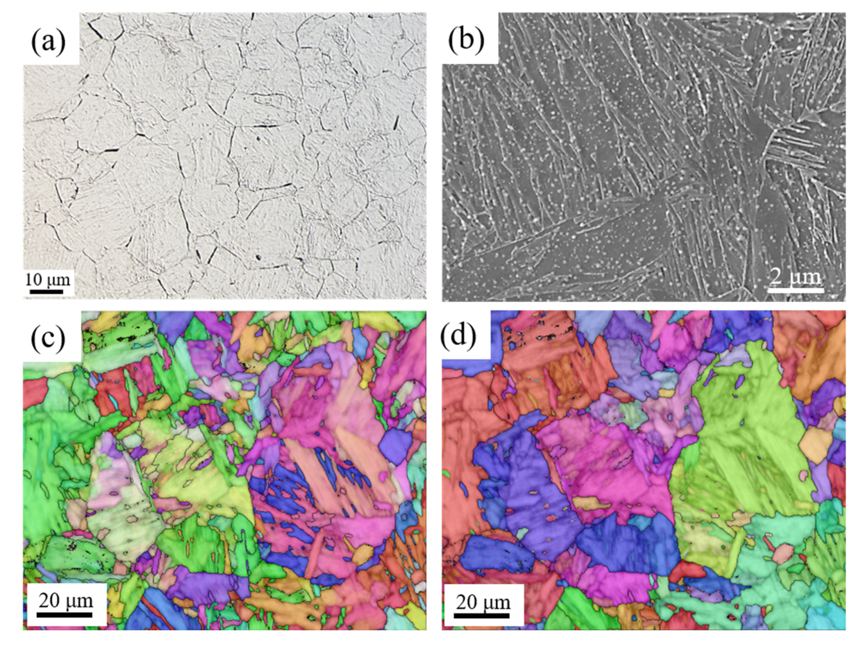
Figure 2 shows the microstructure of the as-quenched 0.1C3Mn steel without warm deformation. It involves an equiaxed and coarse-grained prior austenite structure (Figure 2a), with an average PAGS of 31 ± 11 μm. The martensitic microstructure presents a lath morphology as revealed by the Nital etching (Figure 2b), which is typical for low-carbon steels. A distribution of small carbide particles in the martensite lath was formed, which could be attributed to the auto-tempering effect with a high Ms temperature (417 °C). According to the EBSD results, the martensite laths could also be characterized by the inverse pole figure (IPF) in Figure 2c. Such an orientation mapping can reveal that the prior austenite grain is divided by the groups of martensite variants with the lath morphology. Assuming the Kurdjumov–Sachs (K-S) orientation relationship between martensite and austenite, the prior austenite grains are reconstructed (Figure 2d), showing a similar grain size and features to that revealed by the optical metallography (Figure 2a).
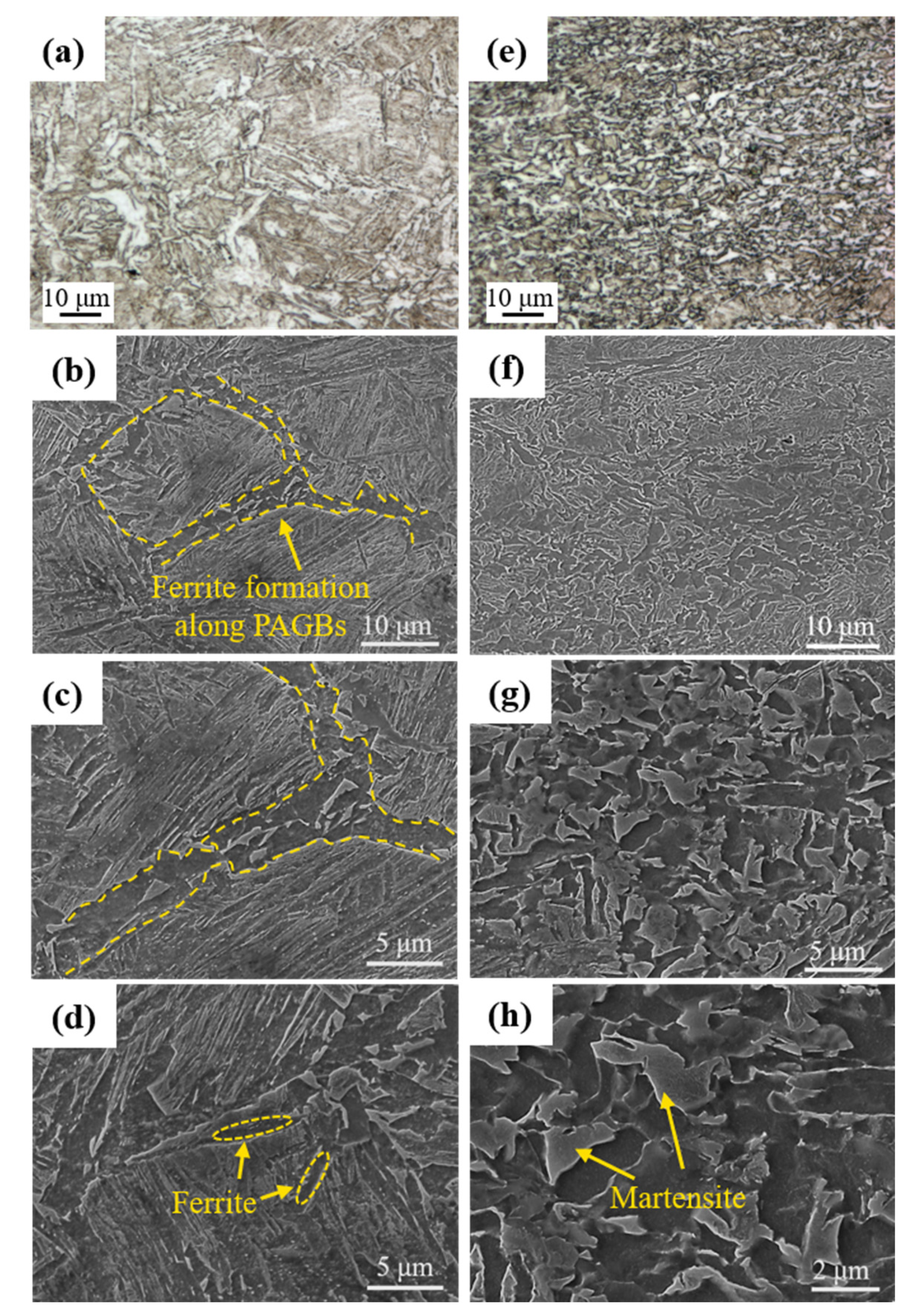
Figure 3 shows the microstructures processed by the warm deformation of austenite. For the sample processed with a 30% compression (650 °C-30%), the optical micrograph (Figure 3a) clearly shows the formation of ferrite, either along the prior austenite grain boundaries or within the austenite grains. The SEM micrographs show that the ferrite along the prior austenite grain boundaries (PAGBs) constitute a network, which is also associated with the distribution of the martensite islands, while the ferrite formed within the austenite grains is mainly of a lenticular shape. However, the sample processed with a 60% compression (650 °C-60%) exhibits different microstructural features. More ferrite phase is formed by the larger warm deformation. The volume fraction of ferrite in 650 °C-60% and 650 °C-30% is 62 ± 4 vol.% and 41 ± 3 vol.%, respectively. In addition, an ultrafine-grained (UFG) ferrite/martensite dual-phase (DP) microstructure has been generated in the 650 °C-60% sample, with an average ferrite grain size of 1.4 ± 0.3 μm. The ferrite grains are uniformly mixed with the martensite islands.
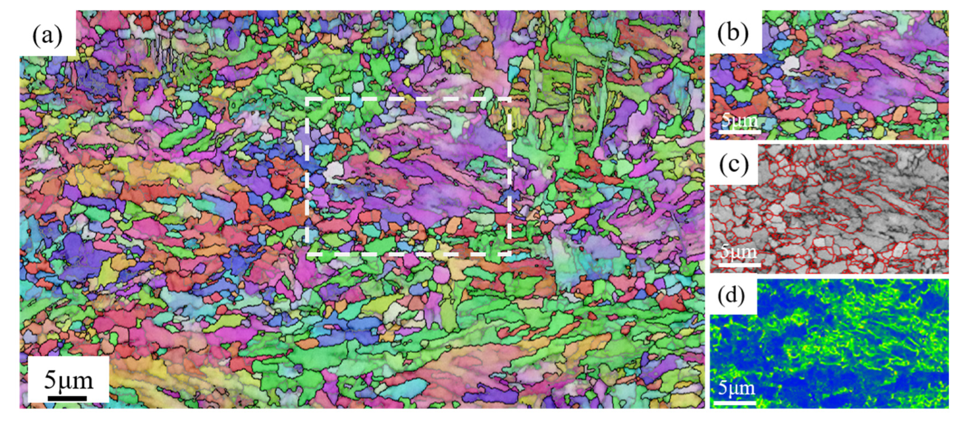
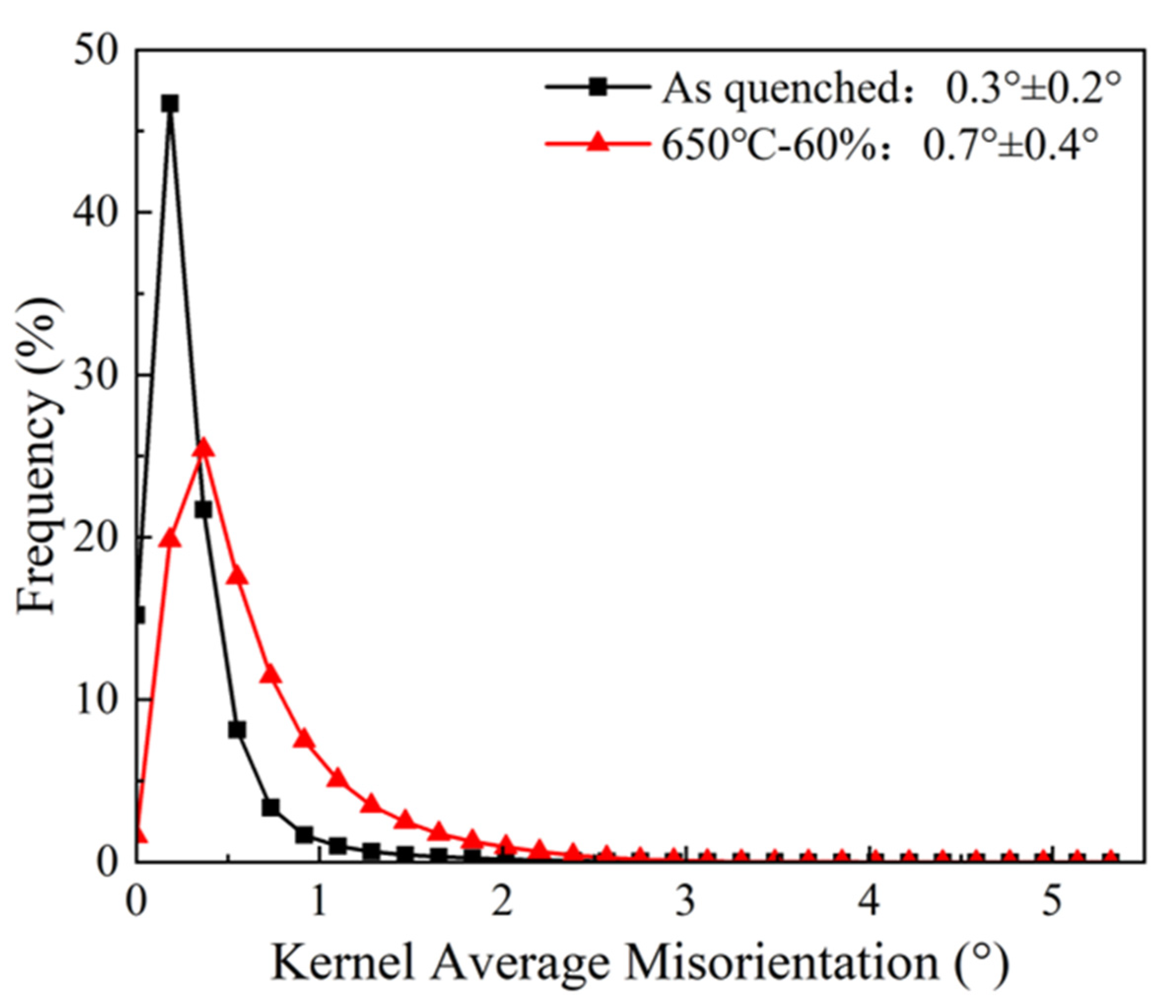
The UFG-DP microstructure of the 650 °C-60% sample is characterized with EBSD. As shown in Figure 4, the microstructure presents a complex morphology, consisting of regions with equiaxed ultrafine ferrite grains and regions of martensite with larger grains. The heterogeneity could also be shown by the spatial distribution of the Kernel Average Misorientation (KAM). As shown in the selected area in Figure 4b,d, the KAM value in the martensitic region is higher than that in ferrite, also indicating a higher dislocation density. In addition, the statistical distribution of KAM values in Figure 5 suggests a higher dislocation density in the 650 °C-60% sample than in the as-quenched martensite, which is presumably the consequence of the dislocations generated by the warm deformation of austenite.
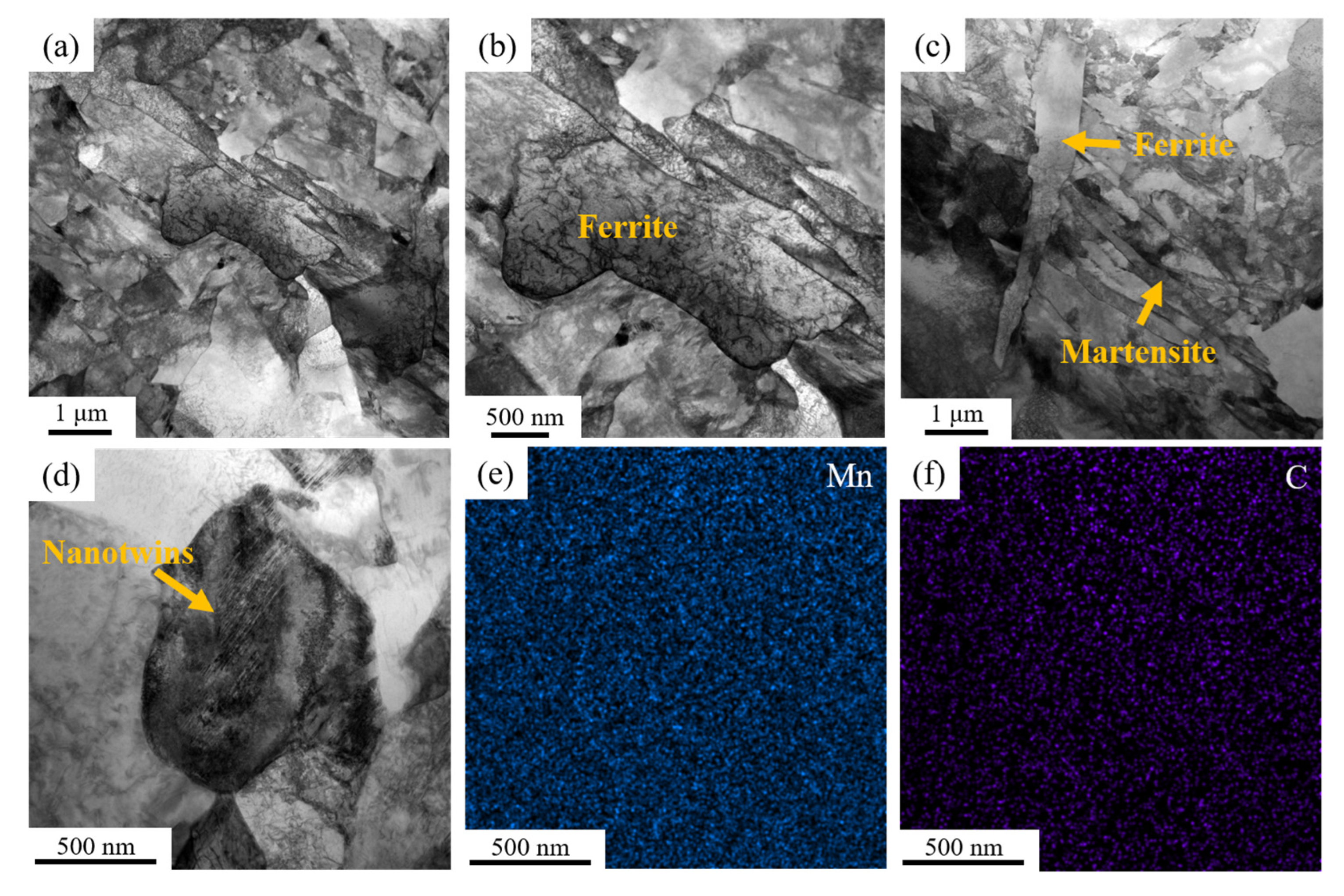
Figure 6 is the detailed TEM observations of the 650 °C-60% sample. Being consistent with the SEM and EBSD micrographs, the sample involves an UFG microstructure with a complex morphology. Note that the ferrite grain highlighted in Figure 6b also contains a high dislocation density, the distribution of which is uniform. The lenticular ferrite is captured in Figure 6c, which subdivides the region dominated by martensite laths. A martensite island, including the formation of nanotwins, is shown in Figure 6d. However, a re-distribution of Mn and C was not observed in the area corresponding to Figure 6d.
Sub-sized uniaxial tensile specimens were machined from the small compression samples as explained in Section 2. The results of the tensile testing are shown in Figure 7, and the tensile properties are summarized in Table 1. According to the tensile curves, the yield strength is reduced when the warm deformation is increased, which can be explained by the reduced amount of martensite with an increasing reduction in compression. However, the dual-phase microstructure facilitates an improved strain hardening capability, resulting in a larger uniform elongation and a comparable true tensile strength. In addition, the UFG-DP microstructure of the 650 °C-60% sample exhibits a higher fracture strain than the as-quenched martensite. All the specimens involve a large post-necking deformation, and the fracture surfaces are covered by small dimples.
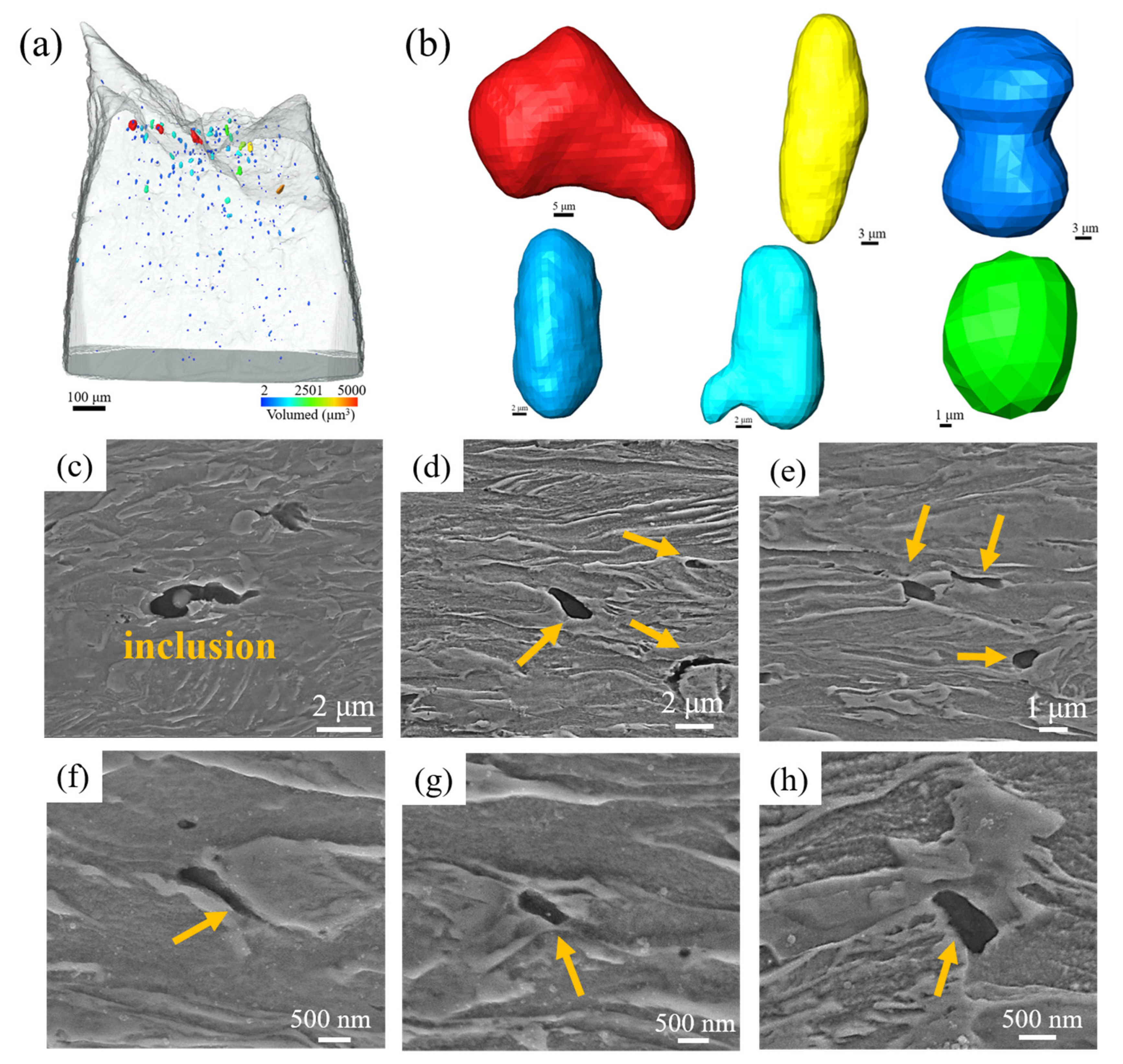
The higher fracture strain of UFG-DP than the low-carbon martensite is different from the results reported in the literature [38]. Therefore, μXCT was used to characterize the evolution of damage in the broken tensile specimens, in order to better understand the fracture behavior. The damage evolution in the as-quenched sample is shown in Figure 8, with voids of different sizes shown in varying colors. The voids are mainly formed after the onset of necking, and the number density of voids increases with increasing strain, associating with an apparent void growth. The voids are not equiaxed but grow into the elongated shape, with the long axis parallel to the tensile direction. Coalescence could occur in neighboring voids to form larger ones. Metallographic observations in the region adjacent to the fracture surface were made to understand the microstructural aspect of void formation. Larger voids were observed to form at the inclusions. Smaller voids are formed at the locations of packet boundaries or lath boundaries, which are presumably the consequences of the localized deformation in the martensitic matrix.
According to Figure 9, the UFG-DP presents a similar trend of damage evolution to the as-quenched low-carbon martensite, in that the voids are mainly formed and grown in the necking zone, especially close to the fracture surface. In addition, the voids evolve into the elongated shape, with the long axis also parallel to the tensile direction. The lengthening of the voids could be a result of the voids’ coalescence. According to the metallographic observations, the voids could either nucleate by martensite cracking or by ferrite/martensite interface decohesion.
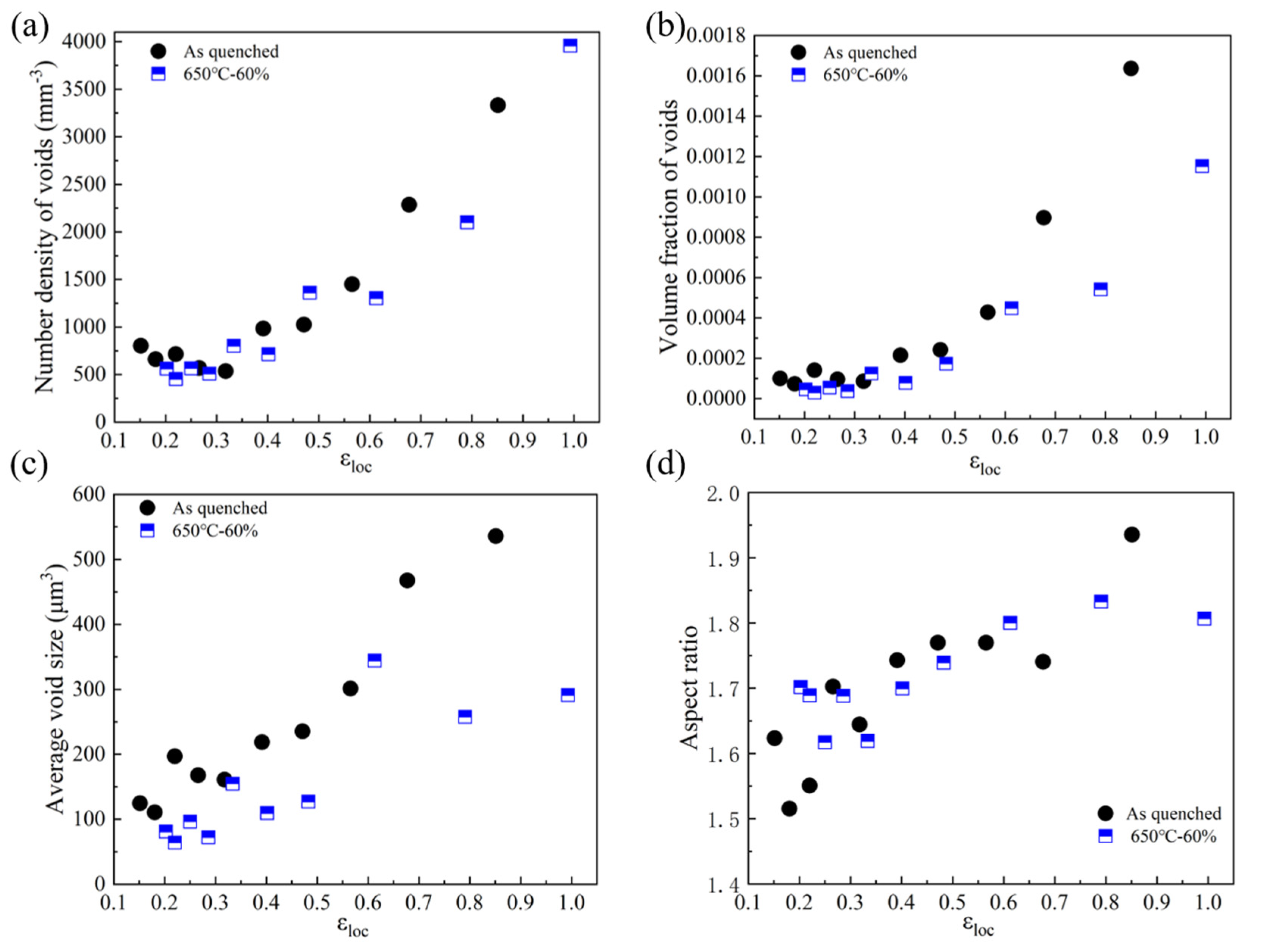
The results of the μXCT are further quantified to compare the damage evolution between the as-quenched and the UFG-DP samples. As shown in Figure 10a, the void density begins to increase after the local strain of 0.35, which could be defined as the void nucleation strain [39]. The number density of voids is similar at a low strain, but the as-quenched martensite involves a larger number of voids at a local strain above 0.6. The volume fraction of voids evolves in a similar trend, and the difference becomes significant at a local strain larger than 0.6 (Figure 10b). In addition, as shown in Figure 10c, the voids grow more significantly in the as-quenched martensite than in the UFG-DP. The increasing aspect ratio with strain in Figure 10d also suggests that the formation of elongated voids is a consequence of plastic deformation. Therefore, the UFG-DP involves a more reduced void nucleation than the as-quenched martensite, and the void growth is more constrained, which could explain the higher fracture strain than the as-quenched sample.

4. Discussion

The advantages of UFG-DP steels have attracted numerous efforts in the development of processing techniques. Previous studies were mainly focused on flash intercritical annealing on the initial microstructure, with an ultrafine or nano-sized structural scale prepared by severe plastic deformation [26,27,28]. By comparison, thermomechanical processing starting from austenite, an extension of the hot-rolled DP scheme, could be more ready to be adopted by facilities in the steel industry. The deformation of austenite generates a set of dislocation substructures, which could significantly accelerate the ferrite transformation, i.e., deformation-induced ferrite transformation. And it is the concurrence of DIFT and ferrite recrystallization that leads to the generation of UFG-DP [34]. In this study, the austenite of the 0.1C3Mn steel is at the undercooled state at 650 °C. However, for the well-annealed austenite, the ferrite transformation is delayed or practically suppressed during the isothermal holding (Figure 1b). Although with the existence of grain boundaries, the well-annealed austenite is still lacking potent nucleation sites for ferrite formation. Upon the deformation of austenite, dislocation cells are formed, and the cell boundaries are more sharply associated, with a larger misorientation when the strain is increased [40]. It was suggested that a critical subgrain misorientation is required to activate the potential nucleation sites, and the critical subgrain misorientation is more likely to be attained first in the vicinity of austenite grain boundaries [41]. This is consistent with the observations in Figure 3, in that the ferrite transformation prefers to occur along the PAGBs.
The temperature was reduced to the warm deformation regime, in order to enhance the generation of UFG-DP. In the conventional works on DIFT, a high deformation temperature was usually involved, and the achievement of a UFG microstructure was limited to the near-surface region of the hot-rolled sheet product [31,42,43]. By conducting the warm deformation of austenite, firstly, the chemical driving force is enhanced and combined with the stored energy due to the dislocation substructures [44], which could enhance the nucleation of ferrite. Secondly, dislocation recovery and grain growth are less significant at a reduced temperature. As shown in Figure 4, the ferrite phase involves an equiaxed grain shape, which is presumably a consequence of the recrystallization. However, the ferrite grain size is sufficiently refined due to the suppression of grain growth. In addition, the dislocations are stored in the ferrite grains as shown by the TEM observations in Figure 6. These observations indicate a lack of annealing processes in the ferrite phase during the thermomechanical treatment, which is essential for achieving the ultrafine structural scale. In addition, as the level of warm deformation of austenite is increased, the continuous generation of dislocation substructures in austenite provides more nucleation sites for ferrite formation, resulting in an increased volume fraction of ferrite.
The UFG-DP microstructure generated in this study presents an improved combination of strength, ductility and fracture strain. The UFG ferrite is known to exhibit a high yield strength (500 MPa) but a negligible strain hardening capability [31], which is attributed to the insufficient strengthening by dislocation storage. The UFG-DP microstructure with a similar ferrite grain size shows a higher yield strength (635 MPa), and, more importantly, a well-rounded stress/strain response and an associated high initial strain hardening rate. The higher yield strength of the 0.1C3Mn UFG-DP could be due to the solid-solution strengthening by the 3wt% Mn and also to the dislocations inherited from the thermomechanical processing as revealed in Figure 6. The enhanced strain hardening capability in UFG-DP, when comparing with the single-phase UFG ferrite, indicates an efficient composite strengthening [25]. Notice that the carbon content in the martensite is moderate (estimated as 0.26wt%) in this case, but the strength of the martensite (estimated as 1700 MPa according to Ref. [25]) remains sufficient to establish a strength contrast and to support the composite strengthening effect.
Another interesting finding is the higher fracture strain of the UFG-DP than the low-carbon martensite. Recent literature [38] has reported that press-hardened steels with a low-carbon martensitic microstructure, although of a higher strength level, could present a higher fracture strain than the commercial DP steels. The lower fracture strain of the DP steels could be mainly attributed to the plastic incompatibility between ferrite and martensite, which leads to the occurrence of ferrite/martensite interface decohesion and/or martensite cracking [45]. A lower martensite hardness has been shown to delay the formation of damage by reducing the strength contrast, but the strength of the DP steels is sacrificed [16,17]. Another direction to address this issue is reducing the ferrite/martensite strength contrast by strengthening the ferrite, which could be accomplished by refining the ferrite grain size. Park et. al. [20] has shown that the microstructure refinement of DP steels reduces the strain partitioning between ferrite and martensite, and the greater plastic deformation in martensite is due to enhanced deformation constraints via the increase in ferrite/martensite interfaces. Another in-depth investigation also evidenced that the strain gradient at the ferrite/martensite interface is reduced by microstructure refinement, and the void growth in the UFG-DP is constrained when compared with coarse-grained counterparts [21], which is consistent with the results in Figure 10c. Besides the increased ferrite strength in the UFG-DP, the moderate carbon content in martensite in this study also contributes to the reduced strength contrast, which also facilitates the delayed damage nucleation as revealed in Figure 10. Therefore, the mechanical properties of the DP steels, i.e., the combination of strength, ductility, and fracture resistance, could be optimized by simultaneously refining the structural scale and designing a moderate carbon content in the martensite.

5. Conclusions

In this study, the warm deformation of austenite in 0.1C3Mn steel has been explored, examining the impacts on its microstructure evolution and mechanical properties. In contrast to the absence of isothermal ferrite transformation in the well-annealed state at 650 °C, the warm deformation of austenite induced the dramatic formation of ferrite. For warm compression by 30%, the ferrite phase was preferably formed along the prior austenite grain boundaries. Compression by 60% at 650 °C resulted in the formation of an ultrafine-grained dual-phase microstructure with a ferrite grain size of 1.4 μm and a ferrite volume fraction of 62%. UFG-DP 0.1C3Mn steel presents a good combination of strength, ductility and fracture resistance. The ferrite grain refinement and the moderate carbon content in martensite reduced the strength contrast between ferrite and martensite, which contributed to the reduced accumulation of damage and thus to a high fracture strain.

Author Contributions

Conceptualization, C.L. and Q.L.; Methodology, Y.W. and C.L.; Validation, Y.W.; Formal analysis, Y.W.; Writing—original draft, Y.W. and Q.L.; Writing—review and editing, Q.L.; Funding acquisition, Q.L. All authors have read and agreed to the published version of the manuscript.

Funding

This study is supported by the National Key Research and Development Program of China [grant number 2023YFB3712703] and Basic Research Program of Jiangsu (BK20232025, BK20232011).

Data Availability Statement

The original contributions presented in this study are included in the article. Further inquiries can be directed to the corresponding authors.

Conflicts of Interest

The authors declare no conflicts of interest.

References

  1. Sun, B.; Kwiatkowski da Silva, A.; Wu, Y.; Ma, Y.; Chen, H.; Scott, C.; Ponge, D.; Raabe, D. Physical metallurgy of medium-Mn advanced high-strength steels. Int. Mater. Rev. 2023, 68, 786–824. [Google Scholar] [CrossRef]
  2. Kazakova, A.A.; Churyumov, A.Y. Microstructure and Mechanical Properties of Fe-30Mn-10Al-3.3Si-1C Light-Weight Steel. Materials 2025, 18, 1258. [Google Scholar] [CrossRef] [PubMed]
  3. Lv, X.; Wang, X.; Lan, A.; Qiao, J. Synergistic Effect of Al and Ni on Microstructure Evolutions and Mechanical Properties of Fe-Mn-Al-C Low-Density Steels. Metals 2024, 14, 495. [Google Scholar] [CrossRef]
  4. Fonstain, N. Advanced High Strength Steels: Physical Metallurgy, Design, Processing, and Properties; Springer International Publishing: Cham, Switzerland, 2015. [Google Scholar]
  5. Allain, S.Y.P.; Pushkareva, I.; Teixeira, J.; Gouné, M.; Scott, C. Dual-Phase Steels: The First Family of Advanced High Strength Steels. In Encyclopedia of Materials: Metals and Alloys; Caballero, F.G., Ed.; Elsevier: Oxford, UK, 2022; pp. 37–62. [Google Scholar]
  6. Ismail, K.; Perlade, A.; Jacques, P.J.; Pardoen, T. Outstanding cracking resistance of fibrous dual phase steels. Acta Mater. 2021, 207, 116700. [Google Scholar] [CrossRef]
  7. Frómeta, D.; Parareda, S.; Lara, A.; Molas, S.; Casellas, D.; Jonsén, P.; Calvo, J. Identification of fracture toughness parameters to understand the fracture resistance of advanced high strength sheet steels. Eng. Fract. Mech. 2020, 229, 106949. [Google Scholar] [CrossRef]
  8. Frómeta, D.; Lara, A.; Grifé, L.; Dieudonné, T.; Dietsch, P.; Rehrl, J.; Suppan, C.; Casellas, D.; Calvo, J. Fracture Resistance of Advanced High-Strength Steel Sheets for Automotive Applications. Metall. Mater. Trans. A 2021, 52, 840–856. [Google Scholar] [CrossRef]
  9. Lai, Q.; Brassart, L.; Bouaziz, O.; Gouné, M.; Verdier, M.; Parry, G.; Perlade, A.; Bréchet, Y.; Pardoen, T. Influence of martensite volume fraction and hardness on the plastic behavior of dual-phase steels: Experiments and micromechanical modeling. Int. J. Plast. 2016, 80, 187–203. [Google Scholar] [CrossRef]
  10. Kadkhodapour, J.; Schmauder, S.; Raabe, D.; Ziaei-Rad, S.; Weber, U.; Calcagnotto, M. Experimental and numerical study on geometrically necessary dislocations and non-homogeneous mechanical properties of the ferrite phase in dual phase steels. Acta Mater. 2011, 59, 4387–4394. [Google Scholar] [CrossRef]
  11. Gao, B.; Liu, Y.; Chen, X.; Sui, Y.; Sun, W.; Xiao, L.; Zhou, H. Heterogeneous plastic deformation and HDI strengthening of the heterostructured dual-phase steels investigated by in-situ SEM-DIC. Mater. Sci. Eng. A 2024, 893, 146149. [Google Scholar] [CrossRef]
  12. Lai, Q.; Bouaziz, O.; Goune, M.; Brassart, L.; Verdier, M.; Parry, G.; Perlade, A.; Brechet, Y.; Pardoen, T. Damage and fracture of dual-phase steels: Influence of martensite volume fraction. Mater. Sci. Eng. A 2015, 646, 322–331. [Google Scholar] [CrossRef]
  13. Landron, C.; Bouaziz, O.; Maire, E.; Adrien, J. Experimental investigation of void coalescence in a dual phase steel using X-ray tomography. Acta Mater. 2013, 61, 6821–6829. [Google Scholar] [CrossRef]
  14. Shi, P.; Ren, Y.; Zhang, X.; Wang, H.; Chen, J.; Pei, Y.; Yan, J.; Zheng, H.; Zhang, J. Role of martensite morphology on mechanical response of dual-phase steel produced by partial reversion from martensite. Mater. Sci. Eng. A 2024, 893, 146116. [Google Scholar] [CrossRef]
  15. Xu, H.; Jia, Z.; Lai, Q. Impacts of Morphology on the Fracture Resistance of the High-Strength Dual-Phase Steels. Materials 2025, 18, 2253. [Google Scholar] [CrossRef] [PubMed]
  16. Mazinani, M.; Poole, W.J. Effect of Martensite Plasticity on the Deformation Behavior of a Low-Carbon Dual-Phase Steel. Metall. Mater. Trans. A 2007, 38, 328–339. [Google Scholar] [CrossRef]
  17. Park, M.h.; Fujimura, Y.; Shibata, A.; Tsuji, N. Effect of martensite hardness on mechanical properties and stress/strain-partitioning behavior in ferrite plus martensite dual-phase steels. Mater. Sci. Eng. A 2024, 916, 147301. [Google Scholar] [CrossRef]
  18. Azuma, M.; Goutianos, S.; Hansen, N.; Winther, G.; Huang, X. Effect of hardness of martensite and ferrite on void formation in dual phase steel. Mater. Sci. Technol. 2012, 28, 1092–1100. [Google Scholar] [CrossRef]
  19. Ogatsu, K.; Ogawa, T.; Chen, T.T.; Sun, F.; Adachi, Y. Dramatic improvement in strength–ductility balance of dual-phase steels by optimizing features of ferrite phase. J. Mater. Res. Technol. 2025, 35, 289–297. [Google Scholar] [CrossRef]
  20. Park, M.h.; Shibata, A.; Harjo, S.; Tsuji, N. Grain refinement of dual phase steel maximizes deformation ability of martensite, leading to simultaneous enhancement of strength and ductility. Acta Mater. 2025, 292, 121061. [Google Scholar] [CrossRef]
  21. Pelligra, C.; Samei, J.; Kang, J.; Wilkinson, D.S. The effect of vanadium on microstrain partitioning and localized damage during deformation of unnotched and notched DP1300 steels. Int. J. Plast. 2022, 158, 103425. [Google Scholar] [CrossRef]
  22. Samei, J.; Zhou, L.; Kang, J.; Wilkinson, D.S. Microstructural analysis of ductility and fracture in fine-grained and ultrafine-grained vanadium-added DP1300 steels. Int. J. Plast. 2019, 117, 58–70. [Google Scholar] [CrossRef]
  23. Xu, X.N.; Li, X.L.; Gou, X.Q.; Li, Y.; Ye, Q.B.; Tian, Y. Synergistic enhancement of strength, ductility, and toughness in a low carbon micro-alloy steel with an ultrafine-grained heterogeneous lamellar structure. Mater. Sci. Eng. A 2023, 878, 145205. [Google Scholar] [CrossRef]
  24. Sun, J.; Xu, B.; Wang, H.; Guo, S.; Yan, Z.; Zhang, J.; Liu, Y. Effect of prior-austenite grain size on the microstructure and mechanical properties of ultrafine-grained dual-phase layer-structured steel produced by hot rolling of intercritical annealed bainite. J. Mater. Res. Technol. 2023, 23, 2440–2453. [Google Scholar] [CrossRef]
  25. Scott, C.P.; Shalchi Amirkhiz, B.; Pushkareva, I.; Fazeli, F.; Allain, S.Y.P.; Azizi, H. New insights into martensite strength and the damage behaviour of dual phase steels. Acta Mater. 2018, 159, 112–122. [Google Scholar] [CrossRef]
  26. Azizi-Alizamini, H.; Militzer, M.; Poole, W.J. Formation of Ultrafine Grained Dual Phase Steels through Rapid Heating. ISIJ Int. 2011, 51, 958–964. [Google Scholar] [CrossRef]
  27. Calcagnotto, M.; Adachi, Y.; Ponge, D.; Raabe, D. Deformation and fracture mechanisms in fine- and ultrafine-grained ferrite/martensite dual-phase steels and the effect of aging. Acta Mater. 2011, 59, 658–670. [Google Scholar] [CrossRef]
  28. Son, Y.I.; Lee, Y.K.; Park, K.T.; Lee, C.S.; Shin, D.H. Ultrafine grained ferrite-marten site dual phase steels fabricated via equal channel angular pressing: Microstructure and tensile properties. Acta Mater. 2005, 53, 3125–3134. [Google Scholar] [CrossRef]
  29. Dong, H.; Sun, X. Deformation induced ferrite transformation in low carbon steels. Curr. Opin. Solid State Mater. Sci. 2005, 9, 269–276. [Google Scholar] [CrossRef]
  30. Beladi, H.; Kelly, G.L.; Hodgson, P.D. Ultrafine grained structure formation in steels using dynamic strain induced transformation processing. Int. Mater. Rev. 2007, 52, 14–28. [Google Scholar] [CrossRef]
  31. Hodgson, P.D.; Hickson, M.R.; Gibbs, R.K. Ultrafine ferrite in low carbon steel. Scr. Mater. 1999, 40, 1179–1184. [Google Scholar] [CrossRef]
  32. Hou, F.; Yu, B.; Akinobu, S.; Tsuji, N. Microstructure evolution during thermomechanical processing in 3Mn-0.1C medium-Mn steel. Mater. Sci. Technol. 2019, 35, 2101–2108. [Google Scholar] [CrossRef]
  33. Rodriguez-Galeano, K.F.; Nutter, J.; Azakli, Y.; Slater, C.; Rainforth, W.M. The effect of the increased strain per pass during the hot-rolling and its effect on the tensile properties of V-Mo and Cr-V-Mo microalloyed dual-phase steels. J. Mater. Sci. 2024, 59, 22228–22249. [Google Scholar] [CrossRef]
  34. Zhao, L.; Park, N.; Tian, Y.; Shibata, A.; Tsuji, N. Dynamic Transformation Mechanism for Producing Ultrafine Grained Steels. Adv. Eng. Mater. 2018, 20, 1701016. [Google Scholar] [CrossRef]
  35. Zhao, J.; Wang, H.; Koenigsmann, K.; Ran, X.; Zhang, P.; Zhang, S.; Li, Y.; Liu, H.; Liu, H.; Ren, L.; et al. Warm Deformation at the (α plus γ) Dual-Phase Region to Fabricate 2 GPa Ultrafine-Grained TRIP Steels. Metals 2023, 13, 1997. [Google Scholar] [CrossRef]
  36. Shu, W.; Fan, Y.; Li, R.; Liu, Q.; Lai, Q. Formation of Ultrafine-Grained Dual-Phase Microstructure by Warm Deformation of Austenite in High-Strength Steel. Materials 2025, 18, 1341. [Google Scholar] [CrossRef] [PubMed]
  37. Xiong, Z.; Jacques, P.J.; Perlade, A.; Pardoen, T. Characterization and Control of the Compromise Between Tensile Properties and Fracture Toughness in a Quenched and Partitioned Steel. Metall. Mater. Trans. A 2019, 50, 3502–3513. [Google Scholar] [CrossRef]
  38. Lai, Q.; Chen, Z.; Wei, Y.; Lu, Q.; Ma, Y.; Wang, J.; Fan, G. Towards the understanding of fracture resistance of an ultrahigh-strength martensitic press-hardened steel. J. Mater. Res. Technol. 2023, 27, 1996–2006. [Google Scholar] [CrossRef]
  39. Maloney, J.L.; Garrison, W.M. The effect of sulfide type on the fracture behavior of HY180 steel. Acta Mater. 2005, 53, 533–551. [Google Scholar] [CrossRef]
  40. Liu, Q.; Hansen, N. Geometrically necessary boundaries and incidental dislocation boundaries formed during cold deformation. Scr. Metall. Mater. 1995, 32, 1289–1295. [Google Scholar] [CrossRef]
  41. Lacroix, S.; Bréchet, Y.; Véron, M.; Quidort, D.; Kandel, M.; Iung, T. Influence of Deformation on Austenite to Ferrite Transformation in Low Carbon Steels: Experimental Approach and Modelling. In Proceedings of the Materials Science and Technology Conference 2003, Chicago, IL, USA, 9–12 November 2003; pp. 367–379. [Google Scholar]
  42. Hurley, P.J.; Hodgson, P.D. Formation of ultra-fine ferrite in hot rolled strip: Potential mechanisms for grain refinement. Mater. Sci. Eng. A 2001, 302, 206–214. [Google Scholar] [CrossRef]
  43. Hickson, M.R.; Russell, R.K.; Hodgson, P.D. The effect of chemistry on the formation of ultrafine ferrite in steel. ISIJ Int. 1999, 39, 1176–1180. [Google Scholar] [CrossRef]
  44. DeBoer, A.; Benrabah, I.E.; Rampelberg, C.; Geandier, G.; Zurob, H. In-situ investigations on the dynamic transformation in steel near the Ae3 temperature. Scr. Mater. 2025, 265, 116737. [Google Scholar] [CrossRef]
  45. Tang, A.; Liu, H.; Chen, R.; Liu, G.; Lai, Q.; Zhong, Y.; Wang, L.; Wang, J.; Lu, Q.; Shen, Y. Mesoscopic origin of damage nucleation in dual-phase steels. Int. J. Plast. 2021, 137, 102920. [Google Scholar] [CrossRef]
Figure 1. Thermomechanical processing of the 0.1C3Mn steel. (a) Schematic illustration of the processing route. (b) Dilatational measurement during the isothermal holding at 600 °C, 650 °C and 700 °C. (c) Temperature variation during the warm deformation. (d) Stress/strain response during the warm deformation.
Metals 15 00699 g001
Figure 2. Microstructure of the as-quenched sample. (a) Optical micrograph of surface etched by Picric acid; (b) SEM micrograph of surface etched by Nital; (c) IPF obtained by EBSD; (d) reconstruction of the prior austenite grains.
Metals 15 00699 g002
Figure 3. Microstructure of the samples after warm deformation. (a) The optical micrograph of the 650 °C-30% sample. (bd) The SEM micrographs of the 650 °C-30% sample. (e) The optical micrograph of the 650 °C-60% sample. (fh) The SEM micrographs of the 650 °C-60% sample.
Metals 15 00699 g003
Figure 4. EBSD characterization of the 650 °C-60% sample. (a) The IPF result. (b) The IPF of the selected area. (c) The distribution of high-angle grain boundaries in the selected area. (d) The distribution of KAM in the selected area.
Metals 15 00699 g004
Figure 5. The distribution of KAM values in the as-quenched martensite and the 650 °C-60% sample.
Metals 15 00699 g005
Figure 6. TEM observations of the 650 °C-60% sample. (ad) The bright-field images. (e,f) The mapping of Mn and C distribution corresponding to the area of (d).
Metals 15 00699 g006
Figure 7. Results of the tensile testing. (a) The engineering and true stress/strain curves. (b,c) The fracture surface observations on the as-quenched sample. (d,e) The fracture surface observations on the 650 °C-60% sample.
Metals 15 00699 g007
Figure 8. Characterization of the damage in the as-quenched martensite. (a) The overall distribution of voids in the necking zone as revealed by μXCT. (b) The typical voids of different sizes. (ch) The SEM observations of the local damage events, which are indicated by the arrows.
Metals 15 00699 g008
Figure 9. Characterization of the damage in the UFG-DP. (a) The overall distribution of voids in the necking zone as revealed by μXCT. (b) Typical voids of different sizes. (ch) The SEM observations of the local damage events, which are indicated by the arrows.
Metals 15 00699 g009
Figure 10. Quantification of the μXCT characterization of damage evolution in the as-quenched and 650 °C-60% samples. (a) The number density of voids. (b) The volume fraction of voids. (c) The average void size. (d) The aspect ratio of the voids.
Metals 15 00699 g010
Table 1. Summary of tensile properties.
SampleYS (MPa)UETS (MPa)εf
EngTrueEngTrue
As-quenched867 ± 250.034 ± 0.0040.033 ± 0.0041090 ± 211128 ± 340.82 ± 0.06
650 °C-30%780 ± 100.048 ± 0.0040.047 ± 0.0031037 ± 161104 ± 250.79 ± 0.08
650 °C-60%635 ± 480.068 ± 0.0030.066 ± 0.003938 ± 331033 ± 110.96 ± 0.08
Disclaimer/Publisher’s Note: The statements, opinions and data contained in all publications are solely those of the individual author(s) and contributor(s) and not of MDPI and/or the editor(s). MDPI and/or the editor(s) disclaim responsibility for any injury to people or property resulting from any ideas, methods, instructions or products referred to in the content.