Article

Current-Carrying Wear Behavior of Cu–TiC Coatings Obtained Through High-Speed Laser Cladding on Conductive Slip Rings of 7075 Aluminum Alloy

School of Mechanical Engineering, Jiangsu University of Science and Technology, Changhui Road, Dantu District, Zhenjiang 212003, China
*
Author to whom correspondence should be addressed.
Metals 2025, 15(7), 688; https://doi.org/10.3390/met15070688
Submission received: 30 April 2025 / Revised: 10 June 2025 / Accepted: 16 June 2025 / Published: 20 June 2025

Abstract

Cu-5wt%TiC coatings were fabricated by high-speed laser cladding on the 7075 aluminum alloy substrate using various scanning speeds to improve its current-carrying wear resistance. The effects of scanning speed on the microstructure, phase, hardness, and current-carrying tribological properties of the coating were investigated using a scanning electron microscope, an X-ray diffractometer, a hardness tester, and a wear tester, respectively. The results show that the increase in scanning speed accelerates the coating’s solidification rate. Among the samples, the coating comprised of equiaxed crystals prepared at 149.7 mm/s presents the best quality, but solidification speeds that are too rapid lead to elemental segregation. The hardness of the coating also decreases with the increase in scanning speed. The coating prepared at 149.7 mm/s exhibits the best wear resistance and electrical conductivity. The wear rate of the coating prepared at 149.7 mm/s at 25 A was 4 × 10⁻³ mg·m−1, respectively. During the current-carrying friction process, the presence of thermal effects and arc erosion cause the worn track to be prone to oxidation, adhesion, and plastic deformation, so the current-carrying wear mechanisms of coatings at 25 A include adhesive wear, oxidation wear, and electrical damage.

1. Introduction

Podded thrusters, characterized by 360° full rotation and vectorial propulsion capabilities, have garnered significant attention in the field of large ships. The conductive slip rings of podded thrusters employ aluminum alloys with light weight, high strength, excellent corrosion resistance, superior conductivity, and outstanding fatigue resistance [1,2]. As the development of the electrification trend in large vessels intensifies, so does the power of podded thrusters, with slip ring power exceeding 10 megawatts, thus escalating the electric current load on individual slip rings. During operation, the conductive slip rings experience a dramatic temperature rise, leading to severe wear and arcing erosion issues [3,4]. Consequently, it is of great significance to prepare electrical contact material coatings to improve the service life of conductive slip rings. Therefore, it is important to study the tribological behavior and failure mechanisms of electrical contact material coatings on conductive slip rings of 7075 aluminum alloy.
Copper (Cu) matrix composites have been widely applied in fields such as electrical contact materials and heat sink components due to their excellent wear resistance, electrical conductivity, thermal conductivity, and self-lubricating properties [5,6]. The conventional preparation methods mainly include sintering, melting, and casting [7,8,9]. Pang et al. [10] added graphene to W–Cu composites by sintering and found that the average breakdown strength of the W–Cu composites decreased after adding graphene. The addition of graphene dispersed the arc and improved the arc erosion resistance of W–Cu. Cui et al. [11] studied the effect of Mg on the CuNiFeP alloy, preparing Cu-0.3Ni-0.3Fe-0.16P-0.1Mg alloy through a process combining vacuum melting and aging treatment. It was found that Mg enhanced the hardness, strength, and electrical conductivity of the CuNiFeP alloy by precipitation strengthening and dislocation strengthening. However, these technologies are energy-intensive and costly to produce, and the processing defects generated during thermal machining will have an adverse effect on the fatigue behavior of the processed material [12]. Surface coating technologies, including laser cladding (LC), electroplating, thermal spraying, and cold spraying [13,14,15,16], can rapidly prepare Cu-based composite coatings on the substrates, effectively improving the substrate properties and saving time costs. Compared with other surface coating technologies, LC has attracted extensive attention due to its distinct advantages including operational simplicity, broad material compatibility, and strong coating–substrate adhesion strength [17,18]. These superior characteristics have established laser cladding (LC) as a preferred technique for the restoration and remanufacturing of critical engineering components [19,20,21].
Yuan et al. [22] obtained NiCr/TiC–10%Cu–10%WS2 coating on 30CrMnSi steel via LC and found that the Cu–WS2, with superior self-lubricating properties, improved the hardness of the coating, resulting in a wear rate of only 62.6% of the NiCr/TiC coating. TiC, characterized by good electrical conductivity, a high melting point, high hardness, a high Young’s modulus, low density, a low thermal expansion coefficient, and excellent chemical stability, is often used to enhance the wear resistance of metal matrix coatings [23,24]. In this case, the Cu coating obtained by the addition of TiC particles displays both high electrical conductivity and high wear resistance.
It is worth noting that the conventional LC technology exhibits insufficient laser power utilization and low scanning speed (0.2–2 m/min), resulting in low coating preparation efficiency, high surface roughness, and large body deformation defects, making it difficult for this method to meet the demands of large-scale industrial production [25]. High-speed laser cladding (HLC) is a later development of conventional LC technology, displaying the advantages of high deposition efficiency and good coating molding quality, enabling the realization of the surface strengthening of non-ferrous metal materials such as Cu, Al, and Ti [26,27,28]. Among these characteristics, many scholars have investigated the effect of scanning speed on the microstructure and tribological properties of high-speed laser cladding coatings. Jian et al. [29] explored the effect of different scanning speeds on the microstructure and hardness of Fe-based coatings by HLC. It was found that the microstructure of the coating was refined with the increase in scanning speed, but the hardness of the coating was decreased. Wang et al. [30] prepared the Fe–Mo–Cr–Y–C–B amorphous coating on 45 steel via HLC and found that the cracking tendency of the coating decreased and the glass phase content increased with the increase in scanning rate, leading to the enhancement of the wear resistance of the coating. In summary, there are few reports on the effect of scanning speed on the wear behavior and failure mechanism of Cu–TiC coatings by HLC.
In this paper, the Cu–TiC coating was fabricated on the conductive slip ring surface of podded thrusters made of 7075 alloy via HLC, and the effect of scanning speed on the microstructure, phase, and hardness of the Cu–TiC coating was investigated. The tribological properties of Cu–TiC coatings under different current-carrying conditions were systematically discussed, and their wear mechanism was also analyzed in detail.

2. Experimental Procedures

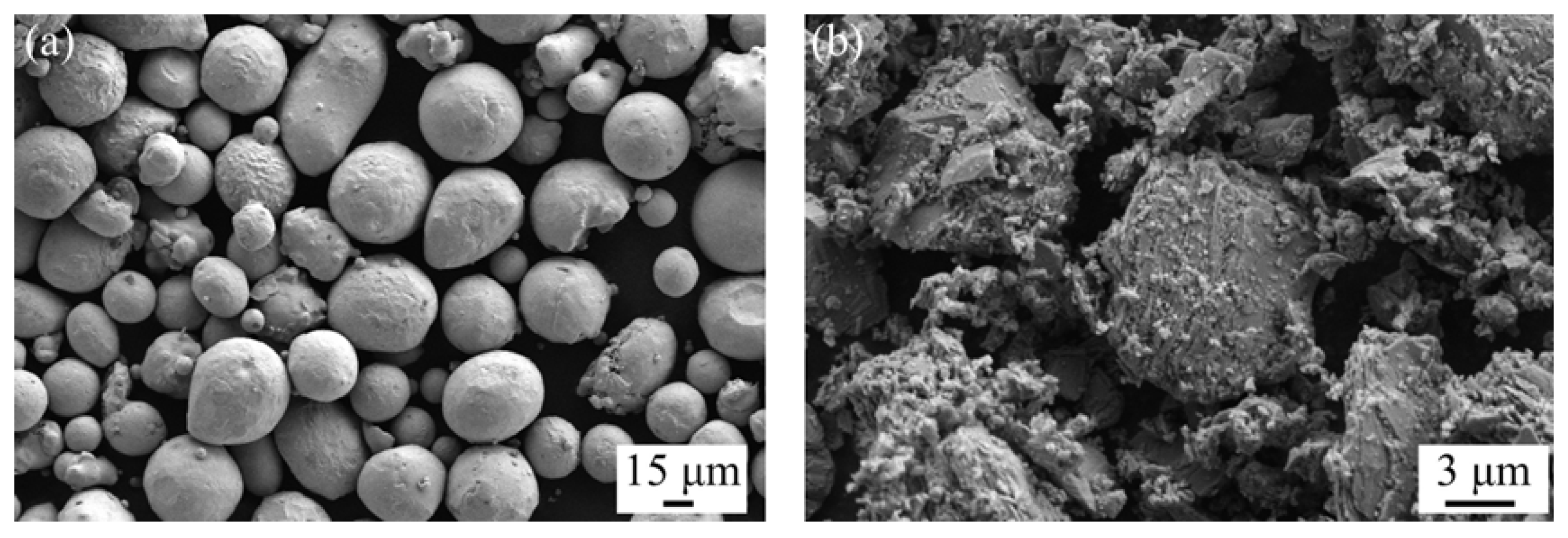
2.1. Materials and Cladding Coatings Preparations

We selected 7075 alloy substrate pipe with dimensions of 1000 × 140 × 10 mm3 (length × diameter × thickness), and the relevant elemental composition is listed in Table 1. The substrate was ground to remove the surface oxide and oil staining before the HLC experiment. The 5 wt% flaked and blocky TiC (purity > 99.9%, Shanghai Maoguo Nano Technology Co., Ltd., Shanghai, China), with particle size distribution of approximately 10 μm, was added to Cu powder (purity > 99.9%, Chengdu Ketailong Alloy Co., Ltd., Chengdu, China), with particle size distribution of approximately 25 μm, using an electronic balance. Figure 1 shows the Cu and TiC powder. The spherical shape of the Cu particle ensured the powder’s fluidity during the HLC powder feeding process. The composite powder was mixed evenly and put into a drying oven, then dried at a temperature of 120 °C for 2 h. Considering the strengthening effect of TiC on Cu coating, a small amount of TiC was selected for the preliminary process exploration to reduce the experimental variables.
The HLC experiment was carried out on an RFL-C2000X type laser device (Wuhan Raycus Fiber Laser Technologies Co., Ltd., Wuhan, China) with a laser wavelength of 1080 nm and a spot diameter of 3 mm, as shown in Reference [31], and the HLC process parameters are as follow: laser powder is 1600W, scanning speed is 86.4, 115.1, 149.7 mm/s, respectively. Angular velocity is 15, 20, 26 r/min, respectively. The powder feeding was performed in a coaxial system with Ar as the shielding gas, preventing the coating from oxidizing during the HLC process.

2.2. Characterization Methods

After the HLC experiment, the coating was cut to a size of 10 × 15 × 10 mm3 using a wire-cut electric discharge machine, ground with #240-2000 SiC sandpaper, and then polished with 1.5 μm diamond grinding paste. The polished coating was etched with a 4% concentration of HNO3 solution for microstructure characterization. The phase of the coating was determined using a Bruker D8 ADVANCE type X-ray diffraction (XRD) device (Billerica, MA, USA), and the parameters were as follows: Al target—Kα radiation; operating voltage of 40 kV; operating current of 40 mA; scanning angle of 10 to 90°, with a scanning rate of 5 °/min at an interval of 0.05°. The LEICA DMI 5000 M type optical microscope (OM) (Leica Microsystems, Wetzlar, Germany), the Gemini Sigma 300 type scanning electron microscope (SEM) (Carl Zeiss AG, Oberkochen, Germany), and its equipped energy dispersive spectrometer (EDS) were used to analyze the microstructure and elemental distribution of the coating. The coating surface was measured using an HVS-1000A-type hardness tester (Laizhou Huayin Test Instrument Co., Ltd., Yantai, China) with a normal load of 300 g and a holding time of 15 s. The twelve measurements were conducted on each coating to ensure the accuracy of the hardness results.

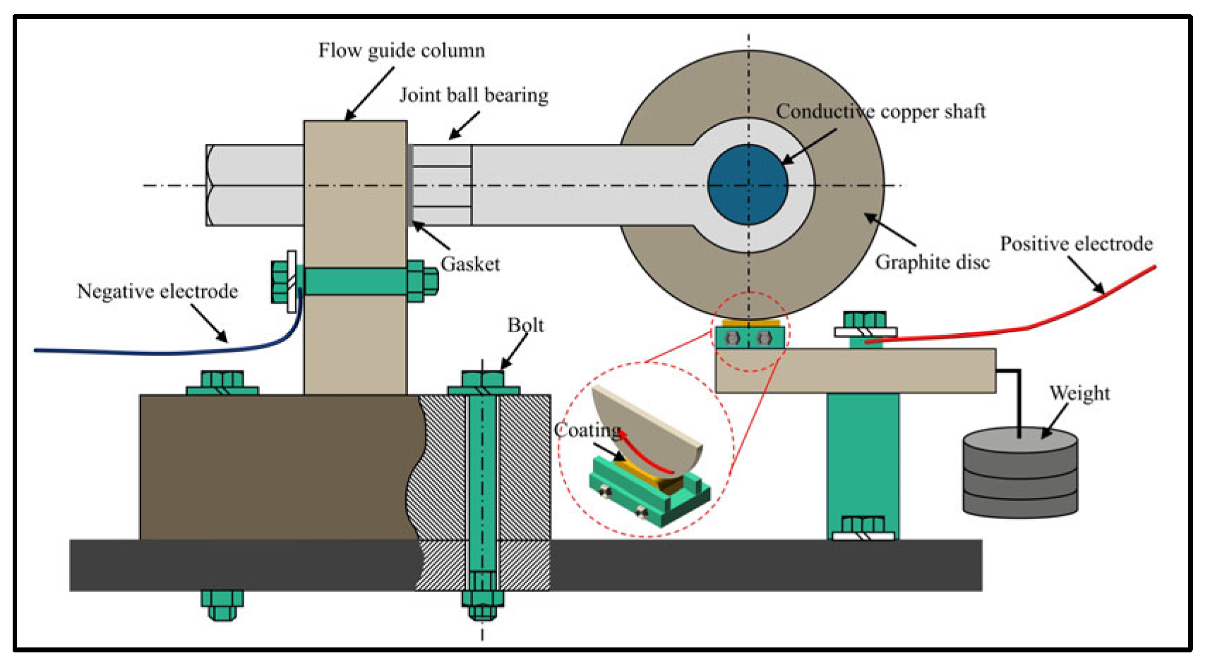
2.3. Current-Carrying Friction-Wear Test

The current-carrying friction-wear tests were carried out on the coatings using a self-designed current-carrying wear tester, where the E-22 graphite disc with the dimension of Ø150 × 10 mm was used as the friction pair to simulate the carbon brush in the conductive slip ring, as shown in Figure 2. The entire current-carrying friction system was powered by 220 V alternating current (AC), and the tests were conducted in a room temperature environment (25 ± 5 °C). The parameters of the friction-wear test are as follows: rotation speed of 250 r/min; normal load of 5 N; test time of 30 min; and working electric currents of 25 A. The working principle of the tester was as follows: the positive electrode wire was connected to the lever, and the negative electrode was connected to the guide column, which was fixed by bolts. The normal loads were applied by hanging weights at the right end of the lever. The electric current passed through the contact area between the coating and graphite disc to produce current-carrying friction. The copper conductive shaft, mounted on the front surface of the graphite disk, efficiently conducted the electrical current to the flow guide column, which directed the current into the negative terminal. This optimized configuration enhanced the thermal dissipation capacity by expanding the effective heat transfer area, thereby effectively mitigating the adverse effects of Joule heating generated by current-carrying friction wear on the operational stability of the testing apparatus. The calculation formula of wear rate (W) is [32]
W = ∆w/L
L = 2 π · R · n · T
where Δw is the wear loss/mg; L is the total wear distance/m; R is the diameter of friction-pair/m; n is the rotation speed/r·min−1; T is the test time/min. After the friction-wear analysis, the worn track and elemental distribution of the coating were further analyzed using SEM and EDS devices.

3. Results and Discussion

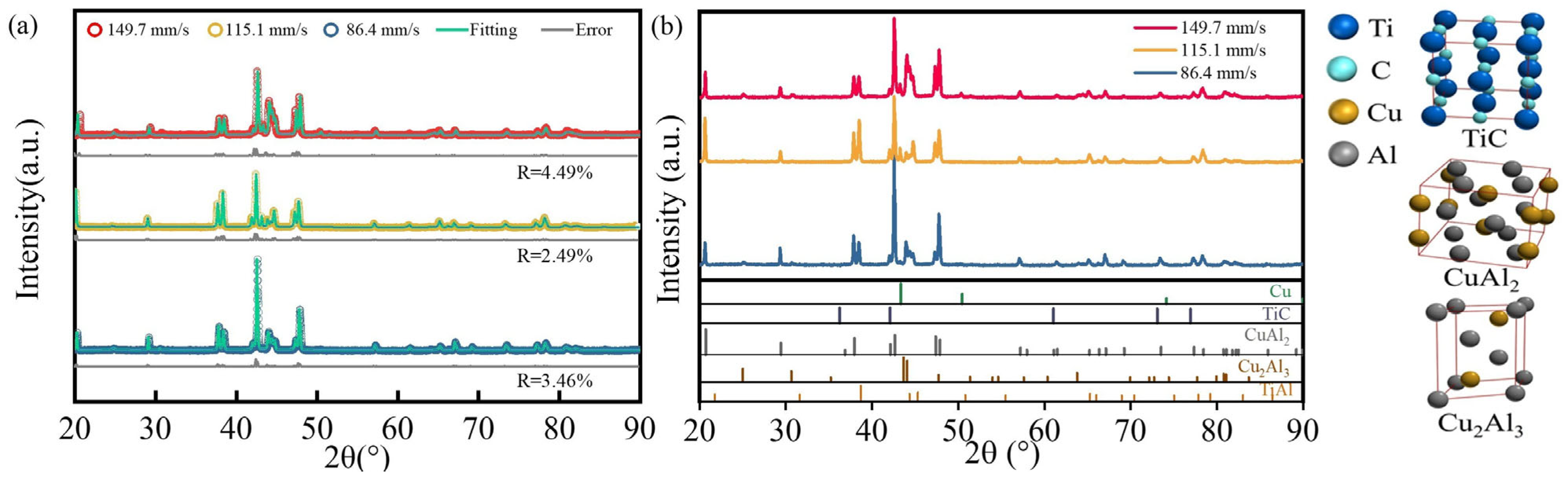
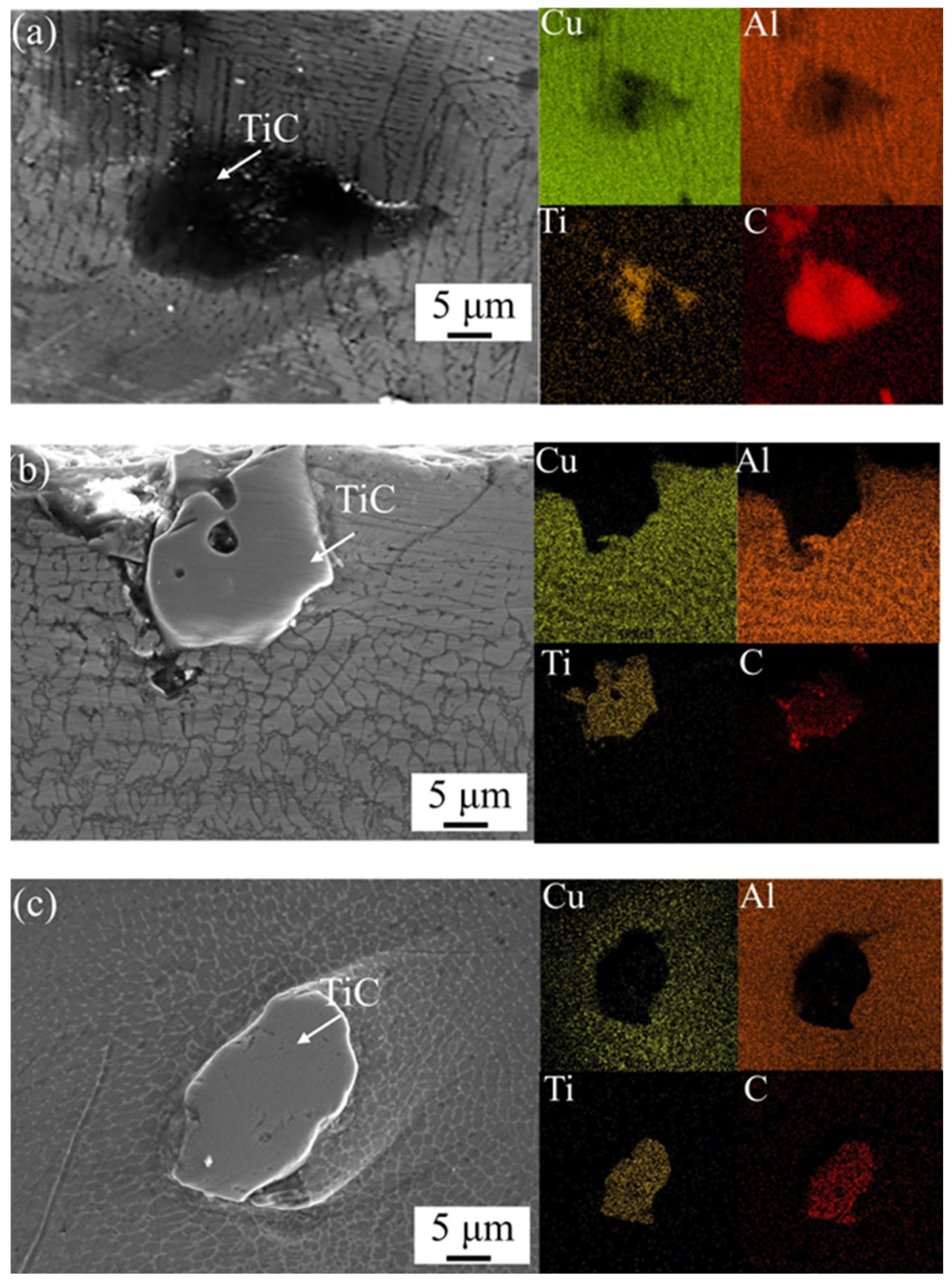
3.1. Microstructure of Coating

The XRD patterns of the Cu–TiC coating through high-speed laser cladding with the scanning speeds of 86.4, 115.1, and 149.7 mm/s are shown in Figure 3. Before phase analysis, the Cu–TiC coatings at different scanning speeds underwent refinement fitting, and their fitting error results were all below 10%, ensuring the accuracy of phase identification. Cu (PDF#04-004-8452), TiC (PDF#04-002-0155), CuAl2 (PDF#04-003-3349), and Cu2Al3 (PDF#04-001-0923) were detected on the coatings, and the corresponding space groups were Fm-3m (225), Fm-3m (225), I4/mcm (140), and P-3m1 (164), respectively. The peak intensity of CuAl2 decreased at 38.6, 42.6, and 47.7°, while the peak intensity of Cu2Al3 increased at 44.0 and 44.5° as the scanning speed increased from 86.4 to 149.7 mm/s, demonstrating that the increase in scanning speed inhibited the formation of the CuAl2 phase and promoted the formation of Cu2Al3.
Figure 4 displays the morphologies and mapping analysis of the Cu–TiC coating prepared through high-speed laser cladding. The microstructure evolution of coatings at the scanning speeds of 86.4, 115.1, and 149.7 mm/s consisted of cellular crystals + columnar crystals, columnar crystals + equiaxed crystals, and equiaxed crystals, respectively. The microstructure of the material was closely related to the temperature gradient (G) and solidification rate (R) during the HLC process. The increase in the scanning speed of coatings reduced the molten pool existence time at high temperatures, which accelerated the R and the undercooling degree of the coating and increased the nucleation rate, eventually leading to the coating microstructure change. The results of mapping analysis also illustrated that the excessive cooling rate of the coating caused the elemental segregation of equiaxed crystals as the scanning speed reached 149.7 mm/s. Figure 5 shows the morphology and element distribution of the TiC particles in the Cu–TiC coatings created at different scanning speeds. It could be found that the TiC was distributed within the coating as blocky particles. At 86.4 mm/s, the high laser energy density caused partial melting of the TiC edges and element interdiffusion between the TiC particles and the coating. When the scanning speed increased to 115.1 mm/s, pores and gaps appeared near the TiC particles, indicating poor adhesion between them and the coating. As the scanning speed increased, the TiC particles were exposed on the coating surface without notable defects, showing strong bonding between the TiC particles and the coating.
Figure 6 shows the cross-sectional morphologies and mapping analysis of the Cu–TiC coatings through high-speed laser cladding. The mapping analysis results show that the mutual diffusion of the Cu and Al elements indicate that a good metallurgical bond was formed between the coating and the substrate during the HLC process. The increase in scanning speed resulted in a shorter reaction time between the laser and the material, reducing the produced specific energy density (E) and the lower powder melting rate. The TiC in the form of the E of coating was calculated as follows [29]:
E = P D · V
where P is the laser power/W; D is the spot diameter/mm; V is the scanning speed/mm·s−1. When the scanning speeds of the coatings were 86.4, 115.1, and 149.7 mm/s, the E calculated by Equation (3) were 6.17, 4.63, and 3.56 J/mm2, respectively, and the corresponding average coating thicknesses in Figure 6a–c were 545, 478, and 324 mm, respectively. The decrease in E and the increase in the solidification and cooling rate, as a result of the enhanced scanning speed, effectively reduced the porosity and cracking defects on the coating. It was noted that no obvious cracks appeared on the bond region between the coating and the substrate at the heat-affected zone (HAZ), ensuring the reliability of the metallurgical bond formation. Given the high sensitivity of 7075 alloy to thermal softening and thermal cracking, the Marangoni convection phenomena became evident during the coating process at scanning speeds of 86.4 mm/s and 115.1 mm/s, and the Marangoni coefficient (Ma) acted as an indicator for measuring the Marangoni convection intensity [33,34]:
M a = γ T T L μ α
where γ/Τ represents the surface temperature tension coefficient related to G; ΔT is the temperature difference between the center and the edge of the molten pool surface, L denotes the radius of the molten pool surface; μ designates the melt viscosity; and α is the thermal diffusion coefficient. The increase in scanning speed led to a reduction in the coating’s E and the melting rate of the powder, shortening the residence time of the laser in the molten pool. Consequently, the fluidity of the molten pool decreased (μ increased), and the temperature gradient within the molten pool diminished (both γ/Τ and ΔT decreased). In this case, the convection in the molten pool area weakened when the scanning speed of the coating reached 149.7 mm/s. The suppressed Marangoni convection reduced the cracking tendency produced by the thermal expansion coefficient mismatch between the substrate and the coating, causing the coating to present the best quality at a scanning speed of 149.7 mm/s.

3.2. Hardness Analysis

The average surface hardness of the Cu–TiC coating through high-speed laser cladding is shown in Figure 7. The coating hardness of 86.4, 115.1 and 149.7 mm/s were in the range of 340–493, 464–222, and 231–118 HV0.3, respectively, and the corresponding average hardness were 402 ± 45, 323 ± 63, and 166 ± 30 HV0.3, respectively. It could be found that the hardness of the Cu–TiC coating decreased as the scanning speed increased, which was attributed to the content change of the intermetallic compounds CuAl2 and Cu2Al3 (Figure 3). Under rapid scanning-induced non-equilibrium solidification conditions, the elevated cooling rate prevented the formation of the thermodynamically stable CuAl2 phase, preferentially facilitating the precipitation of the metastable Cu2Al3 phase [35]. This phase transformation mechanism, characterized by the suppressed development of the high-hardness CuAl2 intermetallic compound, resulted in a consequent reduction in the coating’s overall hardness.

3.3. Current-Carrying Wear Behavior

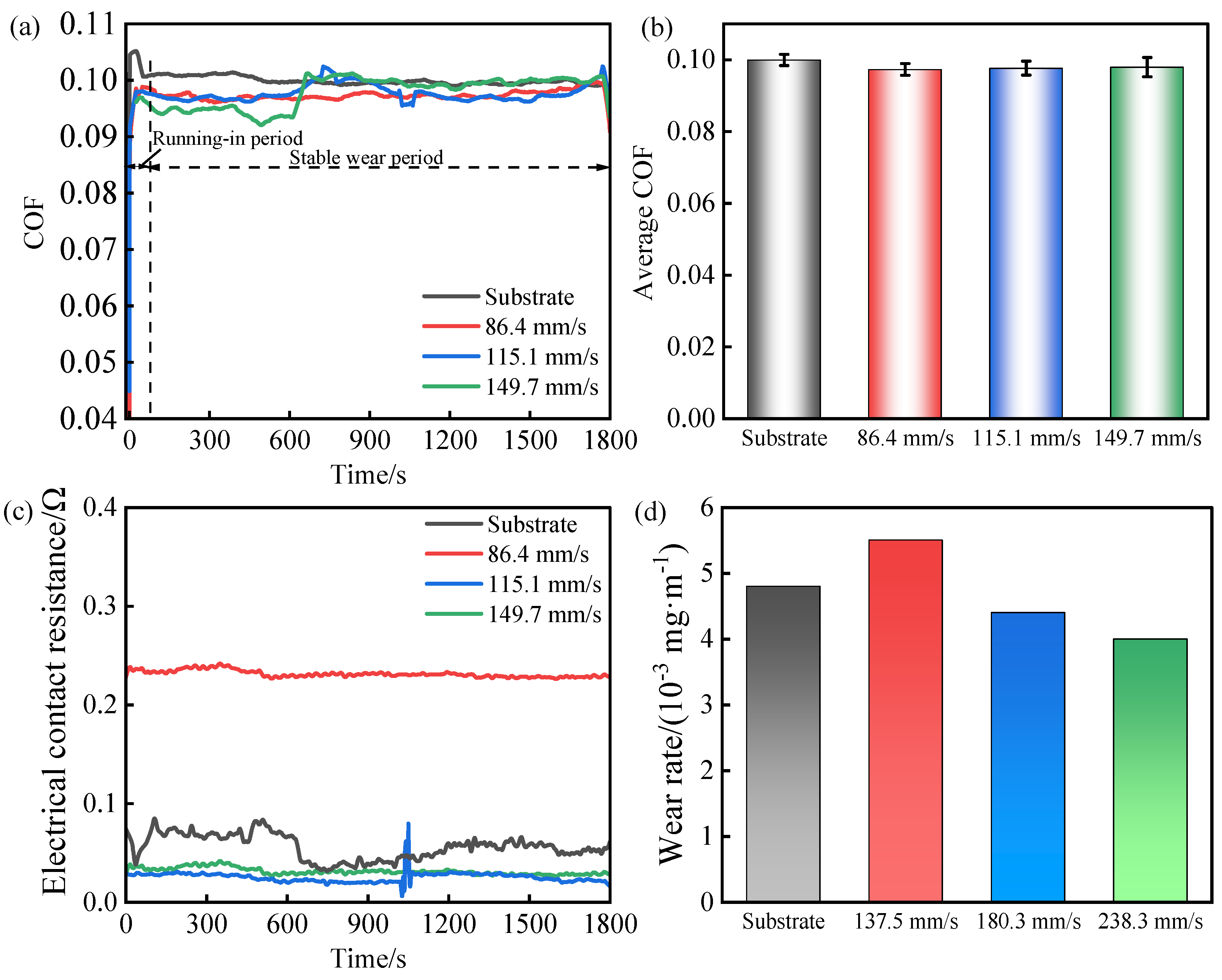
3.3.1. Coefficient of Friction (COF) and Wear Rate

Figure 8a shows the COF vs. the sliding time of the Cu–TiC coatings prepared through high-speed laser cladding under the 25 A electric currents, and the average COF is shown in Figure 8b. The friction between the coating and the friction pair was due to the contact between their respective micro-convex bodies. The contact area of the micro-convex bodies was small during the running-in period, thus resulting in the COF curves of the substrate and the coating showing an upward trend. The contact area of the micro-convex bodies increased as the friction time continued, and the COF curves reached the stable wear period, where they fluctuated around a fixed value. The average COF of the coatings at 25 A was 0.100, 0.097, and 0.098, respectively. During the current-carrying friction, the electric current generated adhesion forces, inducing the adhesion of coating and friction pair, resulting in the COF fluctuations [36].
Figure 8c displays the contact resistance vs. sliding time on worn tracks of the Cu–TiC coatings fabricated through high-speed laser cladding at 25 A. The average contact resistance of the coating at scanning speeds of 86.4, 115.1, and 149.7 mm/s was 0.056 ± 0.012, 0.231 ± 0.003, and 0.025 ± 0.005 Ω, respectively. The standard deviation of the contact resistance indicated that the contact state of the coatings was more stable than that of the substrate during the current-carrying friction process. In general, the average value of contact resistance served as a critical indicator to characterize the conductivity of the material at the current-carrying friction interface [37]. Therefore, the Cu–TiC coatings exhibited better current transfer capability at scanning speeds of 115.1 and 149.7 mm/s. When the friction time reached 1000 s, the contact resistance of the Cu–TiC coating at a scanning speed of 115.1 mm/s showed an obvious upward trend, followed by a rapid decrease, finally settling into a steady state, which was related to the formation and destruction of oxide films. The heat generated by friction, as well as the Joule and arc heat caused by the current, led to an increase in the temperature at the contact points between the coating and the friction-pair [38]. The current appeared attributing to the micro-convex bodies between coating and friction-pair. However, the oxide films formed on the micro-convex bodies hindered the current conduction and increased the contact resistance. When the micro-convex bodies of the coating were sheared by shear stress and could not withstand the contact load, the previously formed oxide films were destroyed, and the contact resistance subsequently decreased.
Figure 8d illustrates the wear rate of the Cu–TiC coatings fabricated through high-speed laser cladding under 25 A. The Cu–TiC coating at a scanning speed of 86.4 mm/s displayed the highest hardness, but its wear resistance was the lowest. This inverse hardness–wear relationship originated from pre-existing cracks on the coating propagating under cyclic stresses, accelerating the material removal. In addition, the 86.4 mm/s of the Cu–TiC coating exhibited the largest contact resistance value, showing the worst electrical conductivity, thereby suffering the most severe arc erosion. In contrast, when the scanning speed of the coating increased to 149.7 mm/s, the wear rates of the Cu–TiC coating was 4 × 10⁻³ mg·m−1, which was 16.7% lower than that of the substrate.

3.3.2. Current-Carrying Tribological Properties

Figure 9 shows the mapping analysis of Cu–TiC coatings prepared through high-speed laser cladding under 25 A. Marked areas A and B represented the morphological characteristics of the 86.4 mm/s coating on the worn track, which will be analyzed in Figure 10. Marked areas C and D corresponded to the worn track morphologies of the 115.1 mm/s coating, which will be discussed in Figure 10. Marked areas E and F depicted the morphological details of the 149.7 mm/s coating on the worn track, and also required analysis in Figure 10. Finally, marked areas G and H illustrated the worn track morphologies of the substrate, and would be analyzed in Figure 10.
The current transmission through the coating and the friction-pair interface generated three primary heat sources: (1) Joule heat caused by the current passage, (2) arc heat triggered by the electrical discharge during the friction process, and (3) frictional heat generated by mechanical friction [39,40]. Arc discharge was a common physical phenomenon during the current-carrying friction process [41]. The synergistic thermal effects (arc heat, Joule heat, and frictional heat) induced coating softening through hardness reduction, resulting in the worn track being susceptible to adhesive transfer and oxidative reactions. As a result, adhesive wear and oxidative wear became the main wear forms of the coating, facilitating the TiC shedding from the wear track. The worn track area of the coating decreased with the increase in scanning speed, and the contents of O and C on the worn track also decreased, demonstrating that the oxidative and adhesive wear of the coating were alleviated due to the increase in hardness.
Figure 10a indicates that the substrate surface underwent severe thermal ablation. During the current-carrying friction process, a large amount of debris was generated, and oxidation occurred. This debris adhered to and piled up on the wear surface, resulting in severe adhesive and oxidative wear.
Figure 10b showcases the worn track morphologies of worn tracks on the Cu–TiC coating prepared at a scanning speed of 86.4 mm/s, revealing that the wear characteristics included ablation pits, plastic deformation, and adhesive tearing. Pre-existing cracks from coating fabrication extended under the combined arc erosion and current-carrying friction stresses. Current transmission through the worn track and friction-pair interface established arc-induced discharge zones in which the cracks formed under the combined effects of shear stress, thermal stress, and compressive stress. These cracks progressively extended during the friction process, ultimately causing bulk material detachment from the worn track via spallation mechanisms. As a result, the ablation pits formed on the worn track as the coating material was removed. The coating at a scanning speed of 86.4 mm/s exhibited the highest contact resistance value (Figure 8c), leading to the generation of more Joule heat that caused the coating micro-convex body region to soft or melt. This thermal softening promoted the plastic flow of worn tracks, significantly enhancing the adhesive interactions during the friction process. In this case, the friction-induced degradation of the coating surface quality made it more susceptible to arcing, exacerbating the wear loss [41].
Figure 10c,d show the worn track morphologies of the Cu–TiC coatings at scanning speeds of 115.1 and 149.7 mm/s, respectively. The number and area of the ablation pits on the worn track decreased significantly compared those observed in Figure 10a, which can be attributed to the coating’s (115.1 and 149.7 mm/s) low contact resistance and high conductivity. The higher conductivity materials reduced the arc discharge probability [42], thereby decreasing the coating wear from electrical erosion. Around the ablation pits, the coating material preferentially underwent shearing, deformation, and tearing under the stress, expanding the pit dimensions and forming spalling pits. Oxidized wear debris from the frictional heating adhered to the spalling pits, forming protective deposits that arrested ablation pit growth. Additionally, the degree of plastic deformation on different regions of the worn tracks was also different, leading to the delamination of the coating, which will be discussed further in the next section.

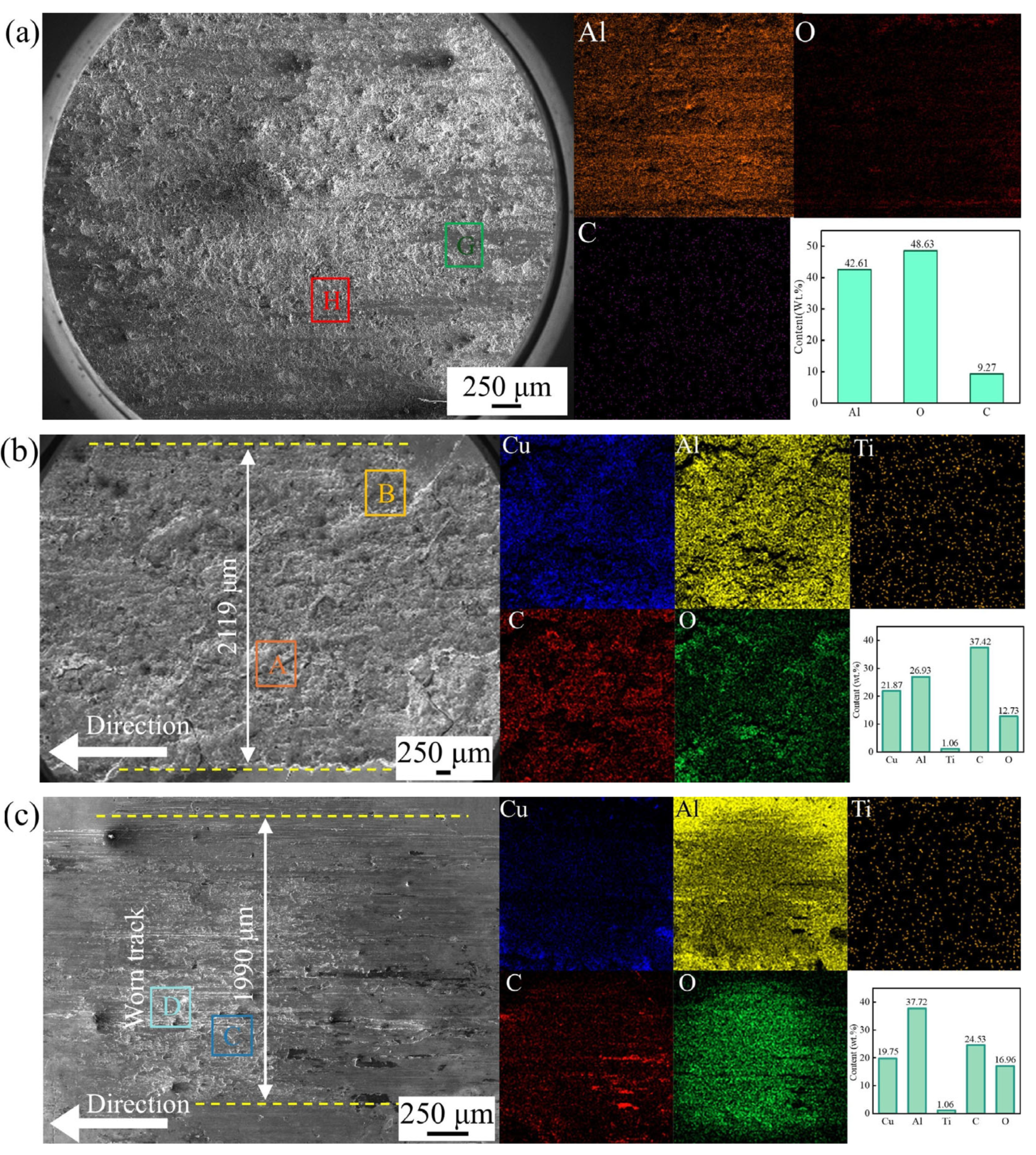
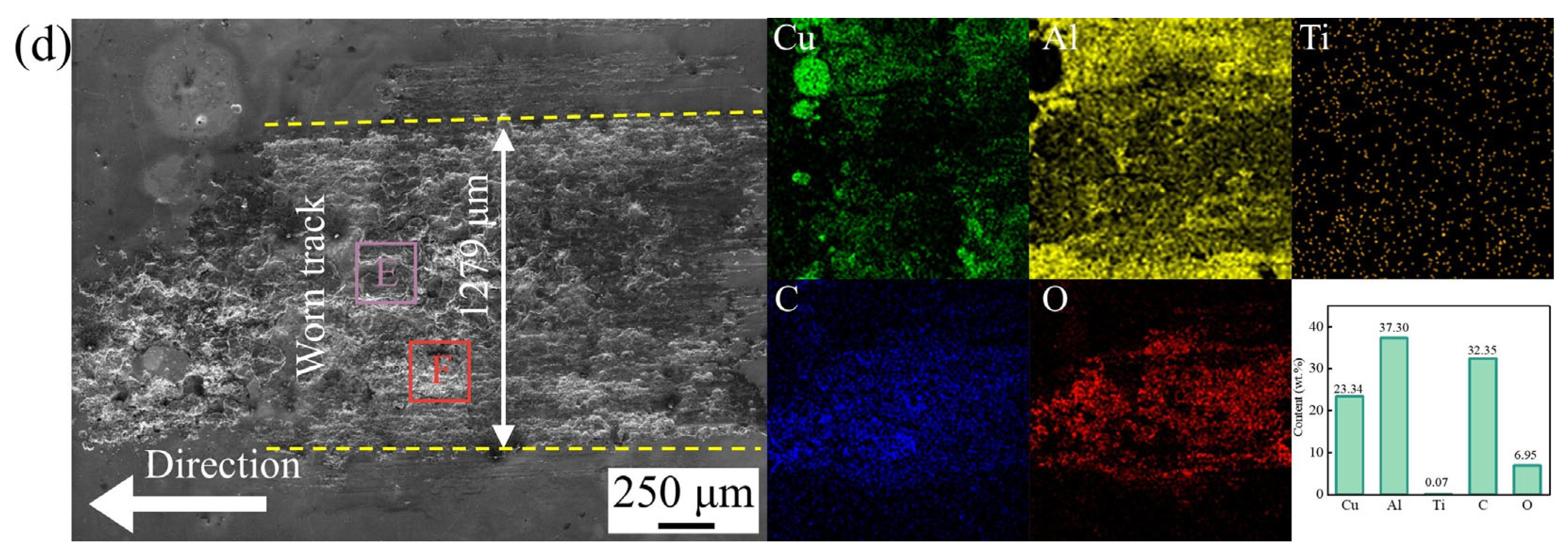
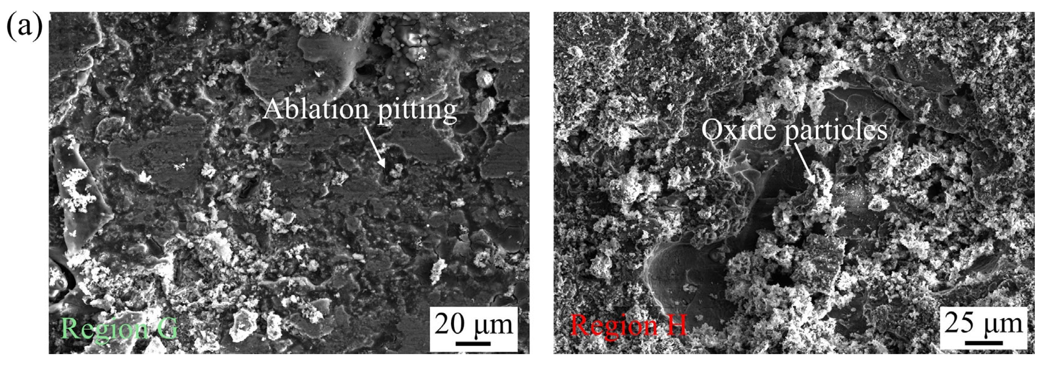
3.4. Failure Mechanism Analysis

The wear failure mechanism model of the Cu–TiC coatings under 25 A current conditions is as follow. The current-carrying friction system exhibited coupling of the current-carrying and frictional performance, characterized by arc-induced electrical damage and mechanical friction on the contact interface [31,38]. Meanwhile, the oxide particles and ablation pits generated by the current-carrying friction accumulated at the worn track of the coating, deteriorating its integrity and initiating arc discharges. Synergistic thermal effects from Joule heating, arc heating, and frictional heating promoted oxidative wear on the worn track. These thermal interactions further enhanced the adhesion tendencies, thereby elevating the surface roughness. Furthermore, the current intensity of the contact interface varied with the gap distance, the stability of the contact resistance film, and the compressive shear stresses when the rough worn track underwent the friction-pair motion [43]. The stochastic arc behavior and inconsistent plastic deformation resulted in adhesive wear-induced delamination on the worn tracks (Figure 10b,c). In addition, the thermal accumulation on the worn surface led to the softening of the coating, thereby reducing the coating hardness and increasing the degree of plastic deformation. Consequently, the average COF values of the coatings with different scanning speeds were similar due to the softening effect noted in the COF results (Figure 8a), making it difficult to improve the wear resistance of the coating through simply increasing the hardness. Given the inverse relationship between the contact resistance of the coating and the scanning speed (Figure 8c), the coating fabricated at a scanning speed of 147.1 mm/s exhibited the best conductivity and lowest current erosion-induced wear loss, thus demonstrating superior current-carrying wear performance (Figure 8d). Thus, the wear failure mechanism of the Cu–TiC coatings prepared at scanning speeds of 86.4, 115.1, and 149.7 mm/s primarily involved adhesive wear, oxidative wear, and arc erosion.

4. Conclusions

This study investigates the current-carrying tribological performance of lip ring surfaces enhanced by high-speed laser cladding (HLC). Cu–TiC coatings with scanning speeds of 86.4, 115.1, and 149.7 mm/s were fabricated on 7075 alloy substrates using HLC, demonstrating that the appropriate process parameters could effectively extend the service life of the substrate. The changes in scanning speed influenced the coating microstructure evolution, phase composition, microhardness, and current-carrying tribological properties. The key conclusions are as follows:
1.
Elevated scanning speeds effectively inhibit the formation of the CuAl2 phase on the Cu–TiC coating, while the content of the Cu2Al3 phase exhibits a corresponding increase, and the microstructure of the coating undergoes a progressive evolution from cellular and columnar crystals → columnar and equiaxed crystals → ultimately, fully equiaxed crystals with scanning speeds increasing from 86.4 mm/s to 149.7 mm/s. The highest coating quality is achieved at a scanning speed of 149.7 mm/s, but the rapid solidification due to the high scanning speed led to elemental segregation of the coating.
2.
The Cu–TiC coating presents the best antifriction property and electrical conductivity when the scanning speed reaches 149.7 mm/s, showing the best wear resistance of all the tested coatings. The wear rates of the Cu–TiC coating at 149.7 mm/s are 4 × 10⁻³ mg·m−1, which are reduced by 16.7% compared to those of the substrate.
3.
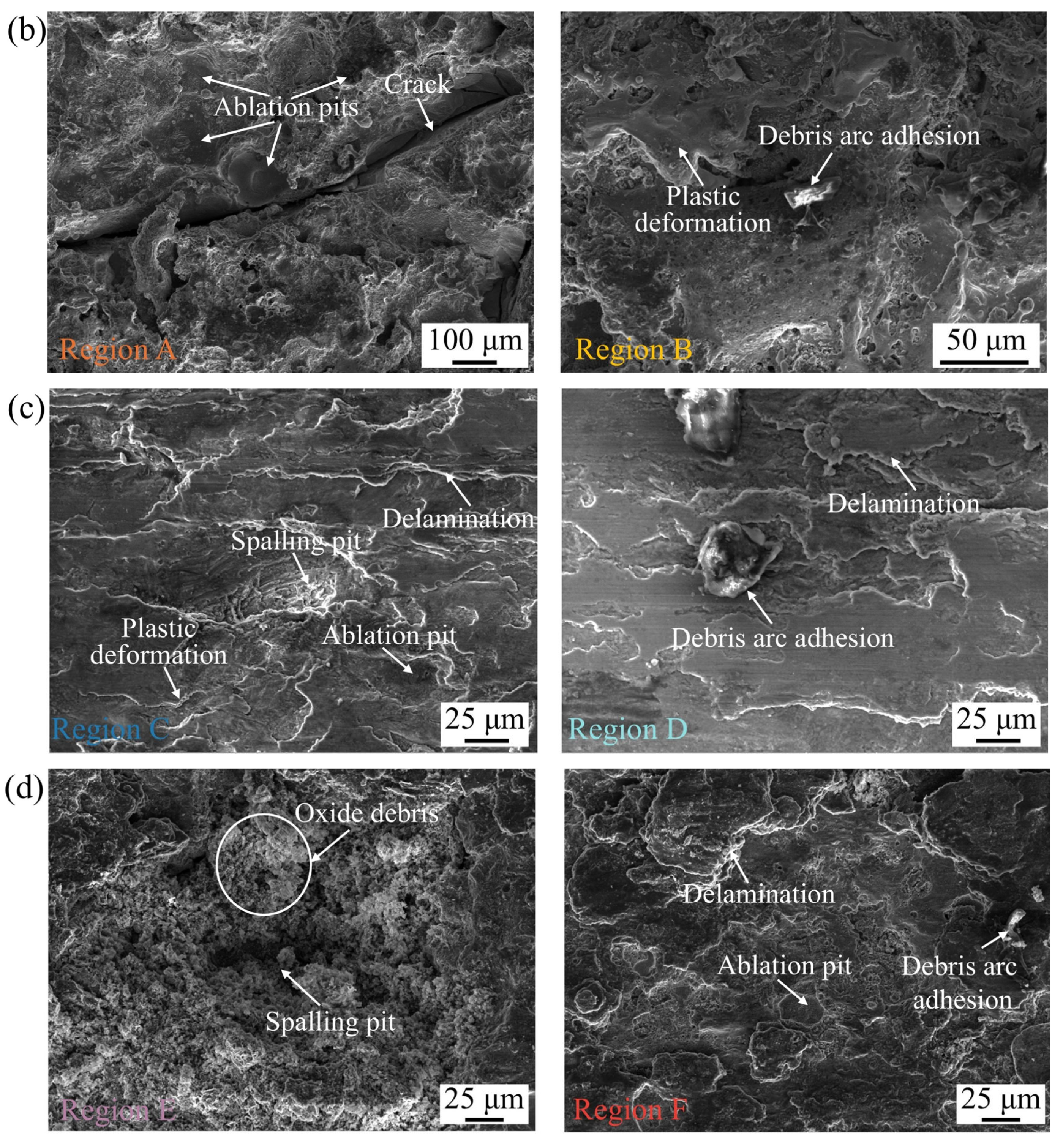
The plastic deformation of the Cu–TiC coatings is intensified by the randomly emerging arc erosion produced by the current, causing the wear mechanism of the coatings at different scanning speeds to comprise adhesive wear, oxidative wear, and electrical damage.

Author Contributions

S.C.: writing—original draft, methodology, investigation, and formal analysis. Y.Z.: methodology and data curation. X.Z.: validation and writing—review and editing. All authors have read and agreed to the published version of the manuscript.

Funding

This research was funded by the National Natural Science Foundation of China, grant number 52005226.

Data Availability Statement

The original contributions presented in this study are included in the article. Further inquiries can be directed to the corresponding author.

Conflicts of Interest

The authors declare no conflicts of interest.

References

  1. Zhang, P.; Yue, X.; Sun, Y.; Zhou, H.; Zhang, J.; Wang, Y. Research on the mechanism of microbial corrosion in the subsurface layer of 7075 aluminum alloy under different corrosion environments with ultra low temperature double increase effect. Vacuum 2024, 227, 113348. [Google Scholar] [CrossRef]
  2. Zhao, Q.; Guo, C.; Niu, K.; Zhao, J.; Huang, Y.; Li, X. Long–term corrosion behavior of the 7A85 aluminum alloy in an industrial-marine atmospheric environment. J. Mater. Res. Technol. 2021, 12, 1350–1359. [Google Scholar] [CrossRef]
  3. Wang, Z.-Z.; Min, S.-S.; Peng, F.; Shen, X.-R. Comparison of self–propulsion performance between vessels with single-screw propulsion and hybrid contra–rotating podded propulsion. Ocean Eng. 2021, 232, 109095. [Google Scholar] [CrossRef]
  4. Zuo, X.; Xie, W.; Zhou, Y. Influence of Electric Current on the Wear Topography of Electrical Contact Surfaces. J. Tribol. 2022, 144, 071702. [Google Scholar] [CrossRef]
  5. Zhao, H.; Feng, Y.; Zhou, Z.; Qian, G.; Zhang, J.; Huang, X.; Zhang, X. Effect of electrical current density, apparent contact pressure, and sliding velocity on the electrical sliding wear behavior of Cu–Ti3AlC2 composites. Wear 2020, 444–445, 203156. [Google Scholar] [CrossRef]
  6. Qian, G.; Feng, Y.; Chen, Y.-M.; Mo, F.; Wang, Y.-Q.; Liu, W.-H. Effect of WS2 addition on electrical sliding wear behaviors of Cu–graphite–WS2 composites. Trans. Nonferrous Met. Soc. China 2015, 25, 1986–1994. [Google Scholar] [CrossRef]
  7. Zhou, T.; Wang, X.; Qin, L.-X.; Qiu, W.-T.; Li, S.-F.; Jiang, Y.-B.; Jia, Y.-L.; Li, Z. Electrical sliding friction wear behaviors and mechanisms of Cu–Sn matrix composites containing MoS2/graphite. Wear 2024, 548–549, 205388. [Google Scholar] [CrossRef]
  8. Feng, J.; Liang, S.; Song, K.; Guo, X.; Zhou, Y. Micro–Nano Dual–Scale Particle–Reinforced TiB2/Cu–0.5Cr Composites Prepared by Vacuum Arc Melting. J. Mater. Eng. Perform. 2020, 29, 3353–3360. [Google Scholar] [CrossRef]
  9. Sankar, B.; Vinay, C.; Vishnu, J.; Shankar, K.V.; Gokul, G.P.K.; Govind, V.; Jayakrishna, A.J. Focused Review on Cu–Ni–Sn Spinodal Alloys: From Casting to Additive Manufacturing. Met. Mater. Int. 2023, 29, 1203–1228. [Google Scholar] [CrossRef]
  10. Pang, Y.; Miao, X.; Zhang, Q.; Chen, Z.; Hao, L.; Zhong, J.; Liang, S. Effect of graphene on the high–energy arc erosion performance of the W–Cu composite. Vacuum 2023, 210, 111827. [Google Scholar] [CrossRef]
  11. Cui, J.; Zhou, R.; Yang, W.; Zhang, C.; Gao, W.; He, J. Effect of Mg on microstructure and properties of Cu–Ni–Fe–P alloy with high strength and high conductivity. Mater. Today Commun. 2024, 41, 110513. [Google Scholar] [CrossRef]
  12. Gryguc, A.; Behravesh, S.B.; Jahed, H.; Wells, M.; Williams, B.; Gruber, R.; Duquett, A.; Sparrow, T.; Lambrou, M.; Su, X. Effect of Thermomechanical Processing Defects on Fatigue and Fracture Behaviour of Forged Magnesium. Frat. Integrità Strutturale 2020, 15, 213–227. [Google Scholar] [CrossRef]
  13. Zhu, Z.; Ren, X.; Jin, K.; Tan, H.; Zhu, S.; Cheng, J.; Guo, J.; Yang, J. Current–carrying tribological properties and wear mechanisms of Mo–containing Cu alloy coatings produced by laser cladding. Tribol. Int. 2024, 200, 110107. [Google Scholar] [CrossRef]
  14. Cao, Z.; Li, R.; Shou, M.; Luo, R.; Wei, B.; Wang, T. Mechanical properties and tribological behaviors of Ag/graphene composite coating under sliding friction and current–carrying fretting. Tribol. Int. 2024, 197, 109811. [Google Scholar] [CrossRef]
  15. Li, J.; Guo, Q.; Tang, Q.; Zhao, G.; Li, H.; Ma, L. Effect of electron beam remelting on microstructure and wear properties of HVOF Ni/WC coatings. Wear 2024, 558–559, 205560. [Google Scholar] [CrossRef]
  16. Chafjiri, Z.S.; Amir, A.-Z.; Seraj, R.-A.; Azarniya, A. Effect of cold spray processing parameters on the microstructure, wear, and corrosion behavior of Cu and Cu–Al2O3 coatings deposited on AZ31 alloy substrate. Results Eng. 2023, 20, 101594. [Google Scholar] [CrossRef]
  17. Liu, Y.; Li, Y.; Tan, N.; Ma, G.; Li, G.; Cai, Y.; Wang, H. Electrical and current-carrying tribological properties of CoCrFeNi–(Mo, Ti, W) high-entropy alloy coatings on copper alloys by infrared-blue composite laser cladding. Surf. Coat. Technol. 2024, 494, 131357. [Google Scholar] [CrossRef]
  18. Grechanyuk, N.I.; Konoval, V.P.; Grechanyuk, V.G.; Bagliuk, G.A.; Myroniuk, D.V. Properties of Cu–Mo Materials Produced by Physical Vapor Deposition for Electrical Contacts. Powder Metall. Met. Ceram. 2021, 60, 183–190. [Google Scholar] [CrossRef]
  19. Zhao, Y.; Liu, Y.; Wu, Y.; Zhang, Z.; Liu, J.; Xie, S.; Deng, L.; Ge, C.; Chen, C.; Chen, H. Steel-based brake disc laser cladding coating preparation method and brake performance study. Eng. Failure Anal. 2025, 167, 108962. [Google Scholar] [CrossRef]
  20. Xiao, D.; Jiang, F.; Song, T.; Wei, C.; Zhang, Y.; Liang, P.; Yang, F. Impact of dilution on the microstructural evolution and corrosion Behavior in High-Entropy alloy coatings applied via laser cladding on marine engineering equipment. Eng. Failure Anal. 2025, 171, 109337. [Google Scholar] [CrossRef]
  21. Jiang, T.-H.; Zhou, S.; Pan, A.-X.; Che, Y.-H.; Li, G.-Q.; Xu, H.-J.; Gong, Y.; Yang, Z.-G. Failure analysis of the abnormal wear of rolling bearing in the centrifugal fan for nuclear power plant. Eng. Failure Anal. 2025, 171, 109353. [Google Scholar] [CrossRef]
  22. Yuan, J.; Yao, Y.; Zhuang, M.; Du, Y.; Wang, L.; Yu, Z. Effects of Cu and WS2 addition on microstructural evolution and tribological properties of self–lubricating anti–wear coatings prepared by laser cladding. Tribol. Int. 2021, 157, 106872. [Google Scholar] [CrossRef]
  23. Liang, Q.; Xu, Y.; Xu, B.; Du, Y. Parameter optimization for in-situ synthesized TiB2/TiC particle composite coatings by laser cladding based on OOA–RFR and U–NSGA–III. Opt. Laser Technol. 2025, 181, 111755. [Google Scholar] [CrossRef]
  24. Chen, G.-D.; Liu, X.-B.; Yang, C.-M.; Zhang, F.-Z.; Li, X.-G.; Zheng, J.; Liu, J. Strengthening mechanisms of laser cladding TiC/FeCoCrNiCu high–entropy composite coatings: Microstructure evolution and wear behaviors. Tribol. Int. 2024, 199, 109979. [Google Scholar] [CrossRef]
  25. Li, Y.; Yuan, X.; Chen, Y.; Yang, G.; Ou, W.; Li, T. Improved microstructure and wear resistance of (CoCrNi)82Al9Ti9 cladding layers via extreme high-speed laser cladding. Surf. Coat. Technol. 2024, 49, 131298. [Google Scholar] [CrossRef]
  26. Liang, Y.; Liao, Z.Y.; Zhang, L.L.; Cai, M.W.; Wei, X.S.; Shen, J. A review on coatings deposited by extreme high–speed laser cladding: Processes, materials, and properties. Opt. Laser Technol. 2023, 164, 109472. [Google Scholar] [CrossRef]
  27. Yuan, W.; Zhu, L.; Luo, C.; Liu, H.; Chen, Z.; He, Y.; Han, E. Enhanced CO2 separation properties by incorporating acid-functionalized graphene oxide into polyimide membrane. High Perform. Polym. 2021, 33, 405–416. [Google Scholar] [CrossRef]
  28. Fu, J.; Gui, W.; Qin, J.; Lin, J.; Ren, X.; Luan, B. High–speed laser–clad 3533-00 Fe–based cemented carbide coatings on nuclear power valve sealing surface to enhanced wear and corrosion resistance. Surf. Coat. Technol. 2024, 480, 130594. [Google Scholar] [CrossRef]
  29. Jian, Y.; Liu, Y.; Qi, H.; He, P.; Huang, G.; Huang, Z. Effects of scanning speed on the microstructure, hardness and corrosion properties of high–speed laser cladding Fe–based stainless coatings. J. Mater. Res. Technol. 2024, 29, 3380–3392. [Google Scholar] [CrossRef]
  30. Wang, K.; Zhang, C.; Qu, F.; Liu, L.; Liu, X. Fe–based metallic glass coatings with suppressed cracks and enhanced wear resistance prepared by extreme high–speed laser cladding. Intermetallics 2024, 175, 108517. [Google Scholar] [CrossRef]
  31. Cheng, S.; Zhou, Y.; Zuo, X. Effect of scanning speed on wear and corrosion behaviors of high-speed laser-cladded Cu-TiC coating. Metals. 2025, 15, 641. [Google Scholar] [CrossRef]
  32. Wang, X.; Song, K.; Duan, J.; Feng, J.; Huang, T.; Xing, J. Current-carrying tribological behavior and wear mechanism of CuW composites with different W content. Tribol. Int. 2024, 200, 110125. [Google Scholar] [CrossRef]
  33. Cui, C.; Wu, M.P.; Miao, X.J.; Gong, Y.L.; Zhao, Z.S. The effect of laser energy density on the geometric characteristics, microstructure and corrosion resistance of Co–based coatings by laser cladding. J. Mater. Res. Technol. 2021, 15, 2405–2418. [Google Scholar] [CrossRef]
  34. Limmaneevichitr, C.; Kou, S. Experiments to simulate effect of Marangoni convection on weld pool shape. Weld. J. 2000, 79, 8. [Google Scholar]
  35. Cui, N.; Zhao, T.; Wang, Z.; Zhao, Y.; Chao, Y.; Lin, H.; Li, D. Strengthening Effect on Microstructures and Properties with CuAl2 and Mg2Si in Forged 2A50 Alloy Under Different T6 Heat Treatment. J. Alloys Compd. 2025, 1010, 178310. [Google Scholar] [CrossRef]
  36. Johnson, K.L. Contact Mechanics; Cambridge University Press: Cambridge, UK, 1987. [Google Scholar]
  37. Da, H.H.; Manory, R.; Sinkis, H. A sliding wear tester for overhead wires and current collectors in light rail systems. Wear 2000, 239, 10–20. [Google Scholar] [CrossRef]
  38. Wang, Y.; Li, J.; Yan, Y.; Qiao, L. Effect of electrical current on tribological behavior of copper-impregnated metallized carbon against a Cu–Cr–Zr alloy. Tribol. Int. 2012, 50, 26–34. [Google Scholar] [CrossRef]
  39. Fu, Y.; Qin, H.; Xu, X.; Zhang, X.; Guo, Z. What are the Progresses and Challenges, from the Electrical Properties of Current-Carrying Friction System to Tribological Performance, for a Stable Current-Carrying Interface. J. Bio- Tribo-Corros. 2022, 8, 4. [Google Scholar] [CrossRef]
  40. Nagasawa, H.; Kato, K. Wear mechanism of copper alloy wire sliding against iron-base strip under electric current. Wear 1998, 216, 179–183. [Google Scholar] [CrossRef]
  41. Guo, F.; Wang, Z.; Zheng, Z.; Zhang, J.; Wang, H. Electromagnetic noise of pantograph arc under low current conditions. Int. J. Appl. Electrom. 2016, 53, 397–408. [Google Scholar] [CrossRef]
  42. Dow, T.A.; Kannel, J.W. Thermomechanical effects in high current density electrical slip rings. Wear 1982, 79, 93–105. [Google Scholar] [CrossRef]
  43. Zhang, Y.; Yang, Z.; Song, K.; Pang, X. Shangguan, Triboelectric behaviors of materials under high speeds and large currents. Friction 2013, 1, 259–270. [Google Scholar] [CrossRef]
Figure 1. HLC powders: (a) Cu power; (b) TiC power.
Metals 15 00688 g001
Figure 2. Schematic diagram of the current-carrying friction.
Metals 15 00688 g002
Figure 3. XRD patterns of Cu–TiC coatings through high-speed laser cladding. (a) refinement peak, and (b) phase identification.
Metals 15 00688 g003
Figure 4. Morphologies and mapping analysis of Cu–TiC coating surfaces through high-speed laser cladding: (a) 86.4 mm/s; (b) 115.1 mm/s; (c) 149.7 mm/s.
Metals 15 00688 g004
Figure 5. Morphologies and mapping analysis of TiC coatings through high-speed laser cladding: (a) 86.4 mm/s; (b) 115.1 mm/s; (c) 149.7 mm/s.
Metals 15 00688 g005
Figure 6. Microstructure of Cu–TiC coating cross-sections through high-speed laser cladding: (a) 86.4 mm/s; (b) 115.1 mm/s; (c) 149.7 mm/s.
Metals 15 00688 g006
Figure 7. Average hardness of Cu–TiC coating surfaces through high-speed laser cladding: (a) 86.4 mm/s; (b) 115.1 mm/s; (c) 149.7 mm/s.
Metals 15 00688 g007
Figure 8. Tribological properties of Cu–TiC coatings fabricated through high-speed laser cladding under 25 A: (a) COF vs. sliding time; (b) average COF; (c) contact resistance vs. sliding time; (d) wear rate.
Metals 15 00688 g008
Figure 9. Mapping analysis of worn tracks on the Cu–TiC coating through high-speed laser cladding under 25 A: (a) substrate; (b) 86.4 mm/s; (c) 115.1 mm/s; (d) 149.7 mm/s.
Metals 15 00688 g009aMetals 15 00688 g009b
Figure 10. Worn track morphologies of Cu–TiC coating prepared through high-speed laser cladding under 25 A: (a) substrate; (b) 86.4 mm/s; (c) 115.1 mm/s; (d) 149.7 mm/s.
Metals 15 00688 g010aMetals 15 00688 g010b
Table 1. The elemental composition of 7075 alloy substrate (wt%).
ElementAlZnCrMgMnCuFeSi
ContentBal.5.10–6.100.18–0.282.10–2.900.301.20–2.000.500.40
Disclaimer/Publisher’s Note: The statements, opinions and data contained in all publications are solely those of the individual author(s) and contributor(s) and not of MDPI and/or the editor(s). MDPI and/or the editor(s) disclaim responsibility for any injury to people or property resulting from any ideas, methods, instructions or products referred to in the content.

