Article

Impact of High Contact Stress on the Wear Behavior of U75VH Heat-Treated Rail Steels Applied for Turnouts

College of Materials, Wuhan University of Science and Technology, Wuhan 430081, China
*
Authors to whom correspondence should be addressed.
Metals 2025, 15(6), 676; https://doi.org/10.3390/met15060676
Submission received: 13 May 2025 / Revised: 12 June 2025 / Accepted: 16 June 2025 / Published: 18 June 2025
(This article belongs to the Special Issue Metallic Materials Behaviour Under Applied Load)

Abstract

Considering the greater contact stress of turnout rails during wear and the development of heavy-haul railways, twin-disc sliding–rolling wear tests were performed on U75VH heat-treated rail steels applied for turnouts under high contact stress ranging from 1980 MPa to 2270 MPa. The microstructure of the worn surfaces was analyzed using optical microscope (OM), scanning electron microscope (SEM), 3D microscope, electron backscatter diffraction (EBSD), and hardness tests. The results indicated that after 10 h of wear, the weight loss was 63 mg at a contact stress of 1980 MPa, while it reached 95 mg at a contact stress of 2270 MPa. At a given contact stress, the wear rate increased with increasing wear time, while a nearly linear increase in wear rate was observed with increasing contact stress. As wear time and contact stress increased, the worn surface showed more pronounced wear morphology, leading to greater surface roughness. Crack length significantly increased with wear time, and higher contact stress facilitated crack propagation, resulting in longer, deeper cracks. After 10 h of wear under a contact stress of 2270 MPa, large-scale cracks with a maximum length of 128.29 μm and a maximum depth of 31.10 μm were formed, indicating severe fatigue wear. Additionally, the thickness of the plastic deformation layer increased with the wear time and contact stress. The surface hardness was dependent on the thickness of this layer. After 10 h of wear under the minimum and maximum contact stresses, hardening rates of 0.39 and 0.48 were achieved, respectively.

1. Introduction

Railway transportation is widely regarded as one of the most ideal modes of transportation, thanks to its numerous advantages such as high efficiency, energy savings, low cost, and safety [1,2,3]. Common rails can be categorized into bainitic rails, austenitic rails, and pearlitic rails. Among these types, the austenite constituent in bainitic rails and austenitic rails can significantly enhance the material’s strength through the TRIP effect [4,5,6,7,8], thus improving the wear resistance. However, due to the high production difficulty and cost, their widespread application is challenging. In contrast, pearlitic rails, which consist of alternating layers of ferrite and cementite, offer high strength and ductility while maintaining relatively low production difficulty and cost [9,10,11]. As a result, pearlitic rail steels are extensively used in railway applications.
The turnout rail is a key component of railways. In contrast to straight rails, the dynamic interaction between the wheel and rail is more complex at turnouts and the contact stress is greater [12,13]. This heightened complexity and stress contribute to more pronounced wear of turnout rails compared to straight rails. Rail wear usually leads to a series of defects in the rail, such as head cracks, bottom bulging, and spalling, which pose safety hazards to train operations [14,15]. Therefore, it is of great significance to study the wear behavior of turnout rails under conditions with large contact stress. However, most of the existing studies have focused on the influence of lower-level contact stress on the wear behavior of pearlitic rails. For example, Seo et al. [16] pointed that the wear rate of KS 60 pearlitic rails increases linearly with the increase in contact stress (ranging from 900 to 1500 MPa). Similar conclusions were also reported in Ref. [17], of which the studied contact stress was between 900 and 1500 MPa. Additionally, Ramalho et al. [1] reported different relationships between contact stress (300–1000 MPa) and wear for EN 260 pearlitic rails and R7 pearlitic wheel steel. The results showed that the wear of the rail decreased slightly with increasing contact stress when the contact stress was below 500 MPa, while the wear increased when the contact stress exceeded 500 MPa. This phenomenon was attributed to the superposition of oxidative wear and work-hardening effects. At lower contact stresses, an increase in contact stress led to greater work hardening, thereby reducing wear. At higher contact stresses, oxidative wear dominated the wear of the rail. Furthermore, the fatigue cracks are also affected by different contact stress. Hu et al. [18] suggested that the fatigue crack size of PG5 pearlitic rail steel, especially crack length, generally shows an upward trend with increasing contact stress ranging from 800 MPa to 1500 MPa. Additionally, Zhang et al. [19] studied the wear behavior of U75V pearlitic rail steel with the contact stress between 1100 MPa and 1800 MPa, and stated that a larger contact stress led to a larger damage degree of rolling contact fatigue cracks. Wang et al. [20] investigated the effect of contact stress ranging from 625 MPa to 1060 MPa on the wear behavior of U75V rail steel. Based on the competition between wear and rolling contact fatigue, their study demonstrated that as the contact stress increases, the crack depth grows steadily, while the wear depth initially increases gradually and then accelerates due to the emergence of large-scale severe spalling pits.
As a heat-treated high-strength rail steel, U75VH is extensively employed at railway turnouts in the field, where wear usually occurs under high contact stress conditions. However, most of the current studies only focused on relatively low contact stress. Railway rail manufacturers have limited literature references for assessing the wear behavior of U75VH rail steel. However, given that railway transportation is developing towards heavier load conditions, rail service is usually carried out under greater contact stress conditions. Therefore, it is necessary to clarify the influence of high-level contact stress on rail wear behavior. In the present study, contact stress ranging from 1980 MPa to 2270 MPa was employed to investigate the influence of high contact stress on the wear behavior of U75VH pearlitic rail steel, aiming to provide a theoretical reference for assessing the wear behavior of U75VH pearlitic rail steel.

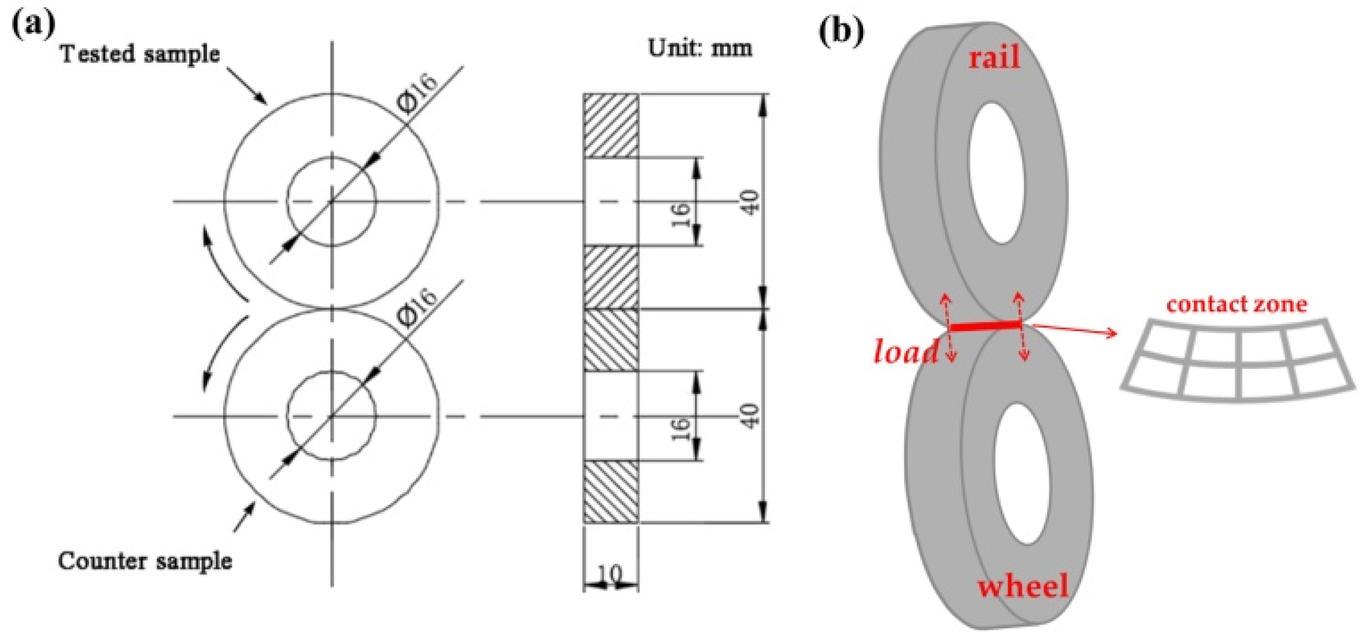
2. Materials and Methods

The experimental steels adopted in the present study were U75VH pearlitic heat-treated rails and a wheel steel, with the alloying compositions detailed in Table 1. The alloying composition was provided by Baowu Steel Group Corporation Limited (Wuhan, China). In these experimental steels, the addition of C contributes to solid solution strengthening [21]. Mn, Ni, and Cr refine the pearlite lamellar spacing [22,23]. Si prevents the formation of continuous network cementite at grain boundary [23]. V and Ti could form (V,Ti)C precipitates with C, thereby enhancing strength [24,25]. The rail hot-rolling process began at a temperature of 1180 °C and finished at 880 °C, after which the rails were air-cooled to room temperature. Subsequently, the rails underwent heat treatment involving heating to 900 °C for normalizing, followed by air-cooling to room temperature.
The rail head and wheel steel were machined into ring samples with an outer diameter of 40 mm, an inner diameter of 16 mm, and a height of 10 mm. Twin-disc sliding–rolling wear tests were performed on rail and wheel samples using an M-2000 rolling wear tester (Jinan Fangyuan Testing Machine Corporation, Jinan, China), as illustrated in Figure 1. The rotation speeds of rail and wheel samples were 180 r/min and 200 r/min, respectively. The corresponding sliding–rolling ratio was calculated to be 10%. This study focuses on simulating the wear behavior of U75VH turnout rail under axle loads of 17 t, 23 t, and 25 t. Specifically, the 17 t axle load corresponds to the maximum allowable axle load for passenger trains operating at speeds of 200 km/h, the 23 t axle load is associated with mixed passenger and freight lines, and the 25 t axle load is related to the open wagons used in coal mines. Given the complex wheel–rail contact relationships in turnout regions, many studies [26,27,28] employed the finite element method to estimate the contact stress at turnouts. Gao [26] estimated that the maximum contact stress at the turnout tip is approximately 52% higher than that on straight tracks. Therefore, based on Hertz contact criterion [29] and Gao’s report, it can be roughly estimated that the contact stress at the corresponding turnout is about 1980 MPa, 2180 MPa, and 2270 MPa, respectively. Since the contact stress at turnouts always varies within a certain range, it is challenging to directly compare it with the rough estimates. However, the contact stress used in this study was sufficiently high to reflect the wear behavior of U75VH rails at turnouts to a certain extent. According to Hertz contact criterion, the corresponding vertical loads were 180 N, 240 N, and 270 N, respectively. A schematic diagram of the twin-disc setup with load direction and contact zone highlighted is shown in Figure 1b. When the two disc samples just come into contact, the contact type is line contact. After loading, because the rail sample is harder (Hrail/Hwheel = 1.6), elastic deformation occurs on the wheel sample surface, leading to a curved contact surface. Each rail sample was subjected to wear for durations ranging from 2.5 h to 10 h. After sliding–rolling wear tests, the rail samples were cleaned with ethanol and weighed. Each group of samples underwent three repeated wear tests. The worn surfaces were observed using a VHX-5000 ultra-depth of field 3D microscope (Keyence Corporation of America, Itasca, IL, USA) and a Nova 400 Nano scanning electron microscope (SEM, Thermo Fisher Scientific Inc., Waltham, MA, USA). To analyze the microstructure of the worn samples, cross-sections were etched with a 4% nital solution and observed using an optical microscope (OM, Carl Zeiss AG, Oberkochen, Germany) to analyze the plastic deformation layer and crack morphology. The cross-sections were then mechanically polished, followed by vibratory polishing with a silica suspension before analyses by electron backscatter diffraction (EBSD) on a Quanta FEG 450 SEM (Thermo Fisher Scientific Inc., Waltham, MA, USA) to further examine the plastic deformation layer. The work-hardening behavior of the rail samples was assessed by measuring the hardness of the worn surface with a test force of 1000 g. The average hardness value was determined by measuring five points on each sample.

3. Results and Discussion

3.1. Wear Weight Loss

Figure 2a illustrates the cumulative weight loss curves of rail samples subjected to three contact stresses. The cumulative weight loss of the rail samples generally exhibits a nearly linear increase with increasing contact stress. Moreover, it is evident that the contact stress had a significant impact on the wear weight loss of the rail steel. Specifically, when the contact stress was 1980 MPa, 2180 MPa, and 2270 MPa, the cumulative wear mass within 10 h was approximately 63 mg, 84 mg, and 95 mg, respectively. Figure 2b shows the variation of the wear rate of rail steel with wear time. As wear time increased, the wear rate increased under the condition with three contact stresses and gradually tended to stabilize. The wear resistance curves in Figure 2c indicate that after reaching the steady wear stage (after 7.5 h), the wear resistance of rail samples tended to remain constant. Moreover, the wear resistance of rail samples under different contact stress conditions was significantly different. Figure 2d shows that the wear rate of rail steel increased almost linearly with the increase in contact stress. Based on Archard’s wear Equation (1) [30,31]
V = K N d H
V represents the volume of worn material, K represents wear coefficient, N , d and H represent the normal load, sliding distance, and hardness of rail steel, respectively. Therefore, the wear coefficient K can be calculated to be 3.780 × 10⁻⁴, 3.68 × 10⁻⁴, and 3.771 × 10⁻⁴ for the sample tested at 1980 MPa, 2180 MPa, and 2270 MPa, respectively. As the contact stress increased, both the wear volume and the vertical force grew simultaneously. Consequently, the wear coefficient of the rail sample exhibited only slight variations with changes in contact stress [16]. The equation can be written as Equation (2):
w ˙ = K ρ ω H p
where w ˙ and p represent wear rate and contact stress, respectively. ρ and ω represent the density of rail steel and rotation speed of rail sample. The similar wear coefficient at different contact stress indicates that the wear rate increases near-linearly with the increase in contact stress. The linear relationship is illustrated in Figure 2d.
Figure 2. Wear weight loss analyses: (a) cumulative weight loss curves; (b) wear rate curves; (c) wear resistance curves; (d) wear rate–contact stress curve. Error bars in (a) indicate mean difference.
Metals 15 00676 g002

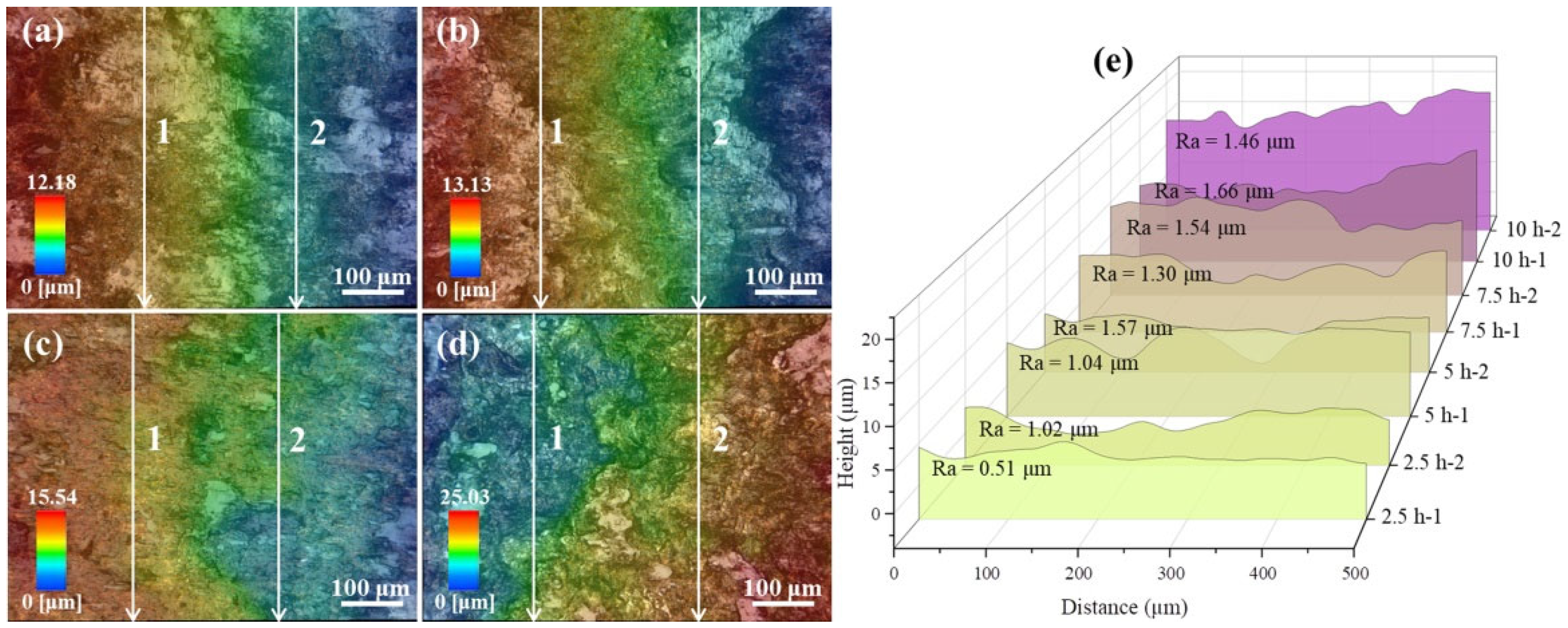
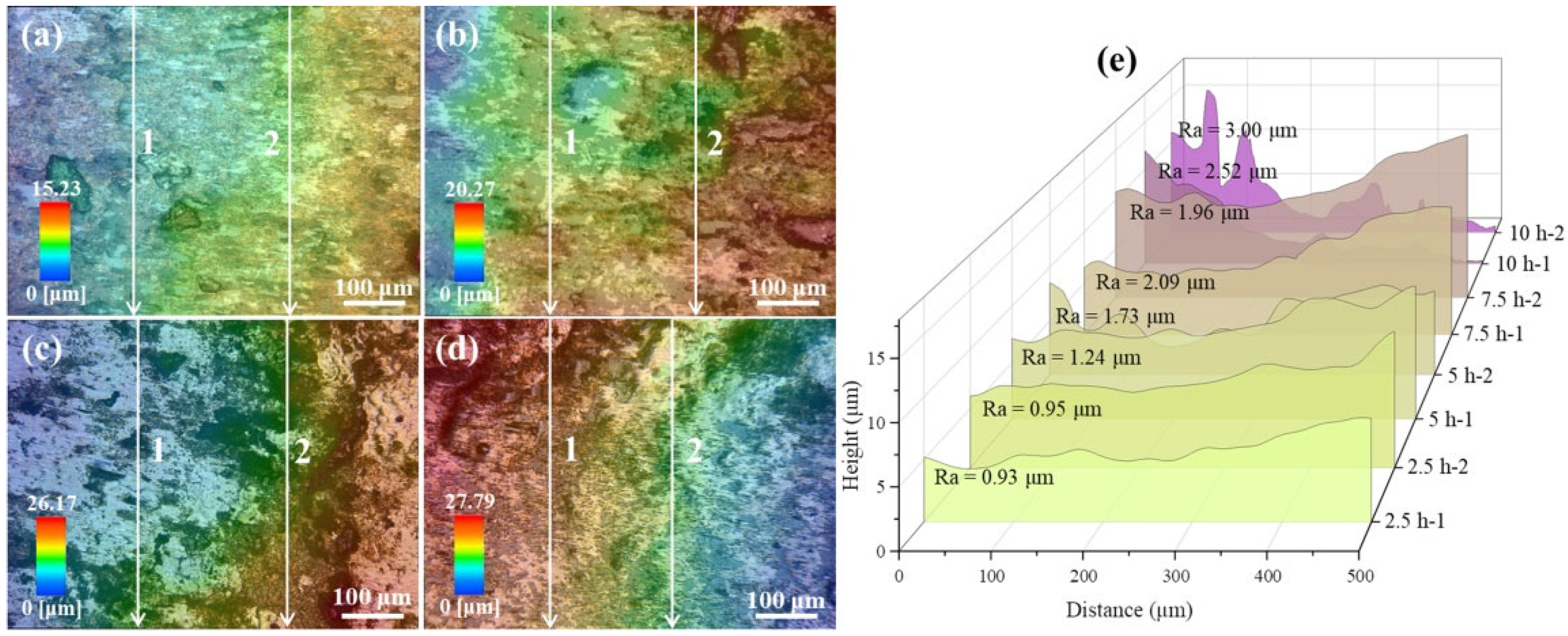
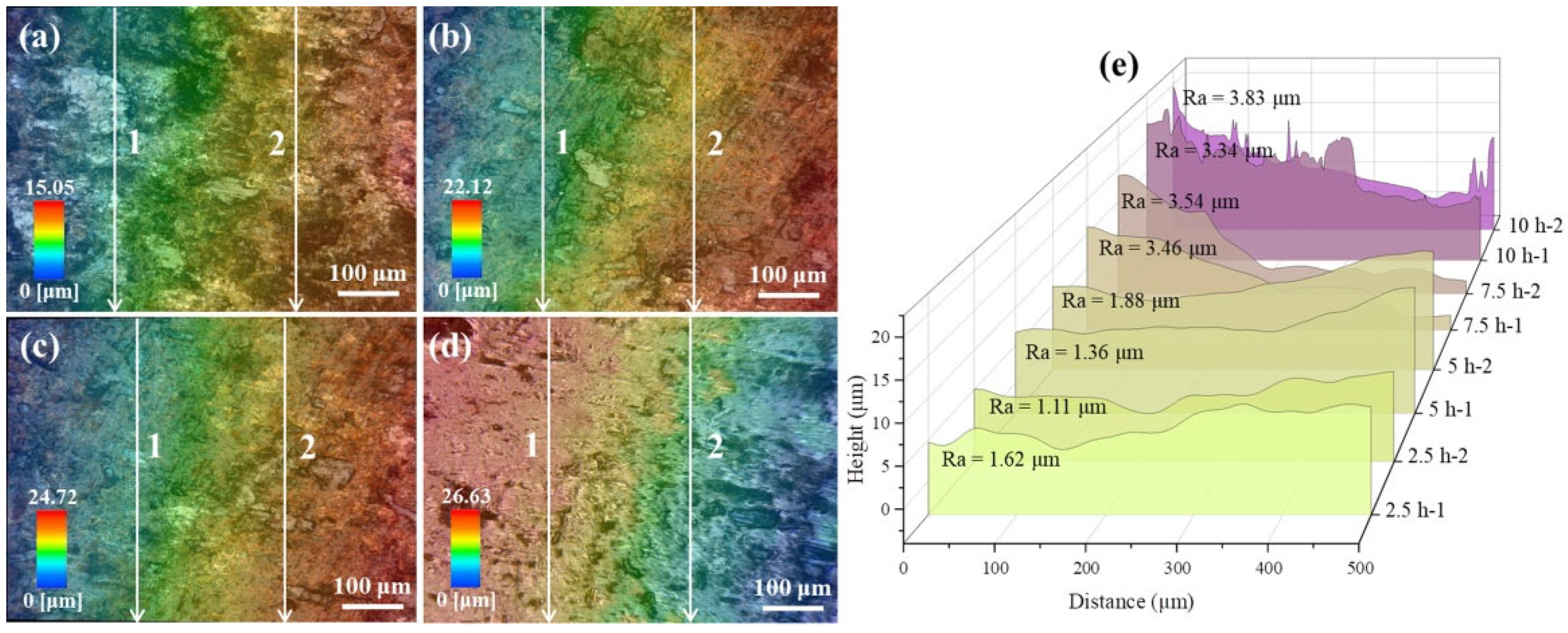
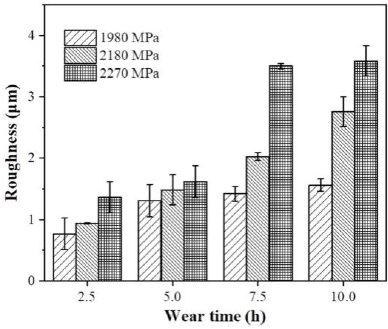
3.2. Worn Surface Morphology
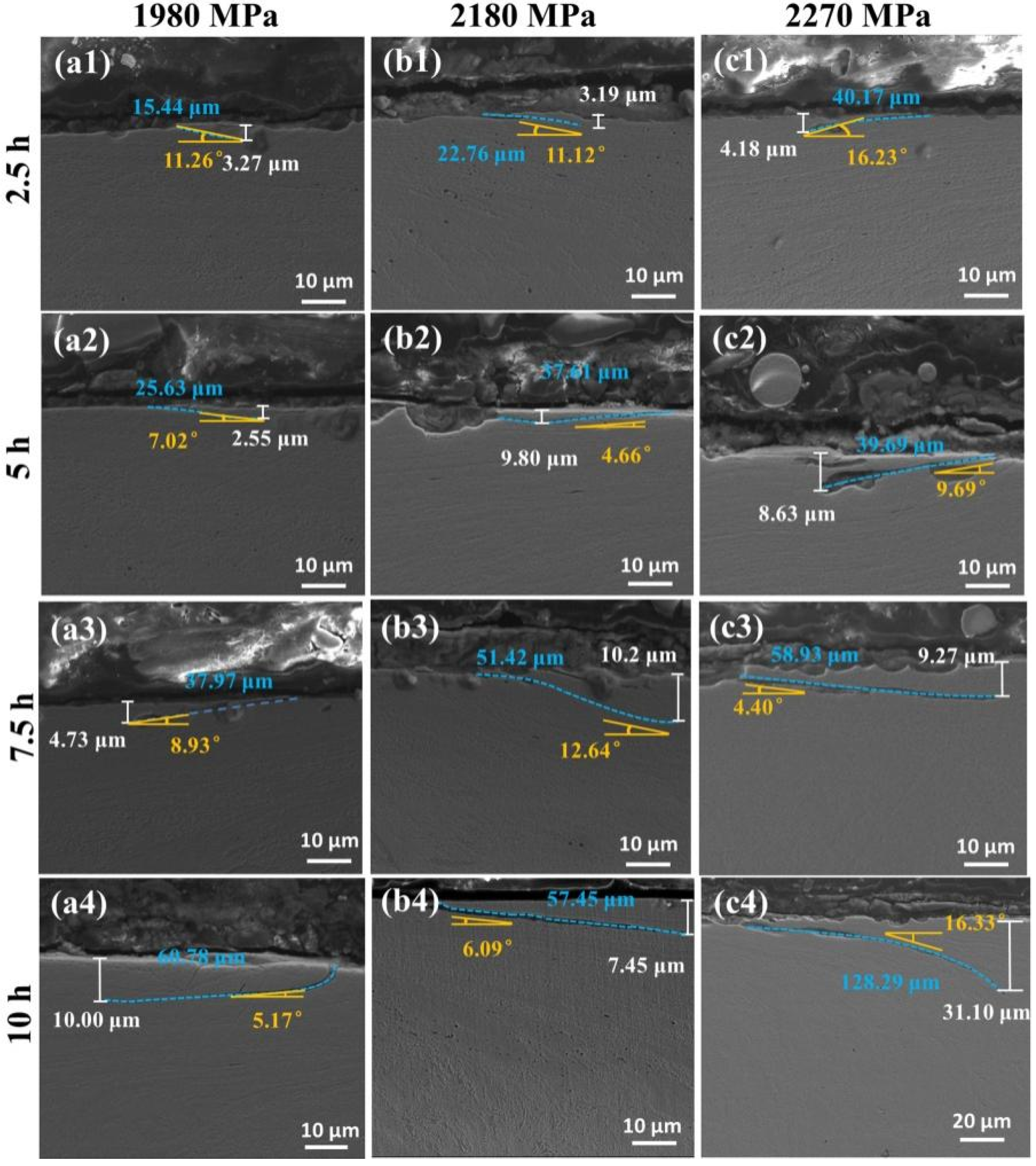
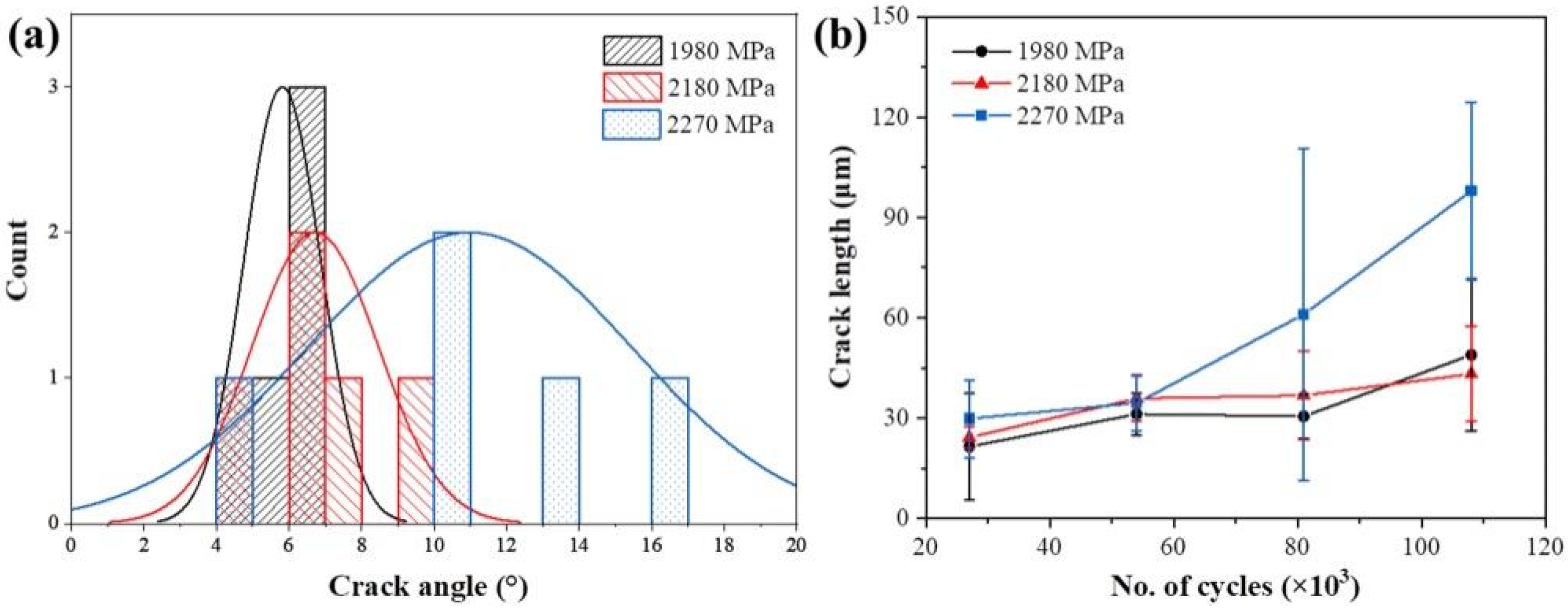
After twin-disc sliding–rolling wear tests, the worn surface morphology of rail samples was observed by SEM and is separately presented in Figure 3. When the contact stress was 1980 MPa, initial wear led to slight peeling on the surface of the rail samples (Figure 3a1), followed by slight spalling in the peeling regions after wear testing for 5 h (Figure 3a2). A great amount of spalling pits became visible in Figure 3a3. After 10 h of wear, the samples exhibited severe spalling, leaving extensive spalling pits on the surface, as observed in Figure 3a4. Additionally, Figure 3b1,c1 illustrate that when the contact stress was 2180 MPa and 2270 MPa, respectively, the surface microstructure began to show slight spalling after only 2.5 h of wear. As the wear process continued, more pronounced spalling occurred, accompanied by more significant spalling pits. The large spalled material adhered to the surface (Figure 3c2), inducing adhesive wear [32]. As presented in Figure 3c4, particles resembling abrasive debris are adhered to the sample surface, which will exacerbate abrasive wear [33]. Generally, as both wear time and contact stress increased, the surfaces tended to develop more pronounced wear features. The adhesive and abrasive wear became more severe.
For the rail samples subjected to wear under varying contact stress conditions, every 2.5 h, a 3D microscope was employed to observe the worn surface and analyze the height profile, as illustrated in Figure 4, Figure 5 and Figure 6. As shown in Figure 4, when the rail samples were subjected to wear under a contact stress of 1980 MPa, the surface profile of the rail sample was relatively smooth in the initial stage of wear. However, as the wear time increased, the height profile gradually became rougher. Figure 5 and Figure 6 further illustrate that this change became more pronounced with the increase in contact stress. Based on the height profile of the worn rail surface, the arithmetic mean of height deviations was calculated to determine the surface roughness Ra. Figure 7 illustrates the variation of surface roughness with wear time under different contact stress conditions. When the contact stress was 1980 MPa, as wear time increased from 2.5 h to 10 h, the roughness increased from 0.77 μm to 1.56 μm. When the contact stress was 2180 MPa, as wear time increased, the roughness increased from 0.94 μm to 2.76 μm. As the contact stress increased to 2270 MPa, the roughness reached 3.59 μm after a wear test for 10 h. Generally, the surface roughness of rail samples tended to increase with both the wear time and the contact stress.

3.3. Fatigue Crack

During the twin-disc sliding–rolling wear tests conducted under varying contact stresses, fatigue cracks were observed to form near the surface of the rail samples, as depicted in Figure 8. It is evident that the length, depth, and angle of these fatigue cracks changed with the contact stress and wear time. To better understand the development of fatigue cracks, their characteristics were statistically analyzed using five SEM micrographs, with the results presented in Table 2.
Comparing the samples worn for 2.5 h and those worn for 10 h across all three contact stresses reveals that as wear time increased, fatigue cracks tended to become longer and deeper. This observation aligns well with the findings of Li et al. [34]. Additionally, after wear tests for 10 h, contact stress significantly influenced fatigue crack characteristics, particularly crack length. For samples worn under a contact stress of 1980 MPa, fatigue crack lengths were primarily in the range of 22.69–63.09 μm. When contact stress rose to 2180 MPa, crack lengths concentrated in the range of 28.97–57.45 μm. At a contact stress of 2270 MPa, fatigue crack lengths extended to the range of 79.41–128.29 μm. Notably, as presented in Figure 8c4, a large crack with a length of 128.29 μm, a depth of 31.10 μm, and an angle of 16.33° is observed on the sample surface, highlighting a significant stress concentration near the contact surface. Figure 9 presents a histogram for the crack angle after 10 h of wear testing under different contact stress, indicating that a larger contact stress is likely to result in a larger crack angle.
The crack propagation can be described using the well-known Paris law [35], as shown in Equation (3):
d a d n = c · K b
where a and n represent the crack length and number of cycles, and c and b are material constant. K is the range of the stress intensity factor during a load cycle, which depends on the load and crack length. When discussing crack propagation, it is necessary to take into account the effects of wear, as crack propagation and wear occur simultaneously. Therefore, Equation (4) [36] can be obtained:
d a d n = c · K b 1 s i n θ d z d n
where θ and z represent the crack angle and the thickness of removed material. Figure 9b plots the relationship between crack length and the number of cycles. It can be observed that when the contact stress is relatively low (1980 MPa and 2180 MPa), the crack length increases slightly with the increasing cycles. However, when the contact stress reaches maximum (2270 MPa), the crack propagation rate significantly increases. This indicates that when the contact stress is relatively lower, the degree of fatigue fracture is comparable to wear. In contrast, when the contact stress is higher, the extent of fatigue damage exceeds wear.
Generally, higher contact stress tended to increase the length, depth, and propagation angle of cracks, thereby exacerbating fatigue wear. Since cracks tended to propagate towards relatively lower energy levels to achieve minimal crack propagation resistance [37], lower contact stress provided less energy for crack propagation. Consequently, fatigue cracks that initiated from the surface and subsurface of rail samples under lower contact stress typically extended in the direction of shear flow or parallel to the surface at a small angle [38]. In contrast, under higher contact stress, more energy was available for crack propagation, making it easier for cracks to develop into the material at larger angles, resulting in long and deep large-sized cracks.

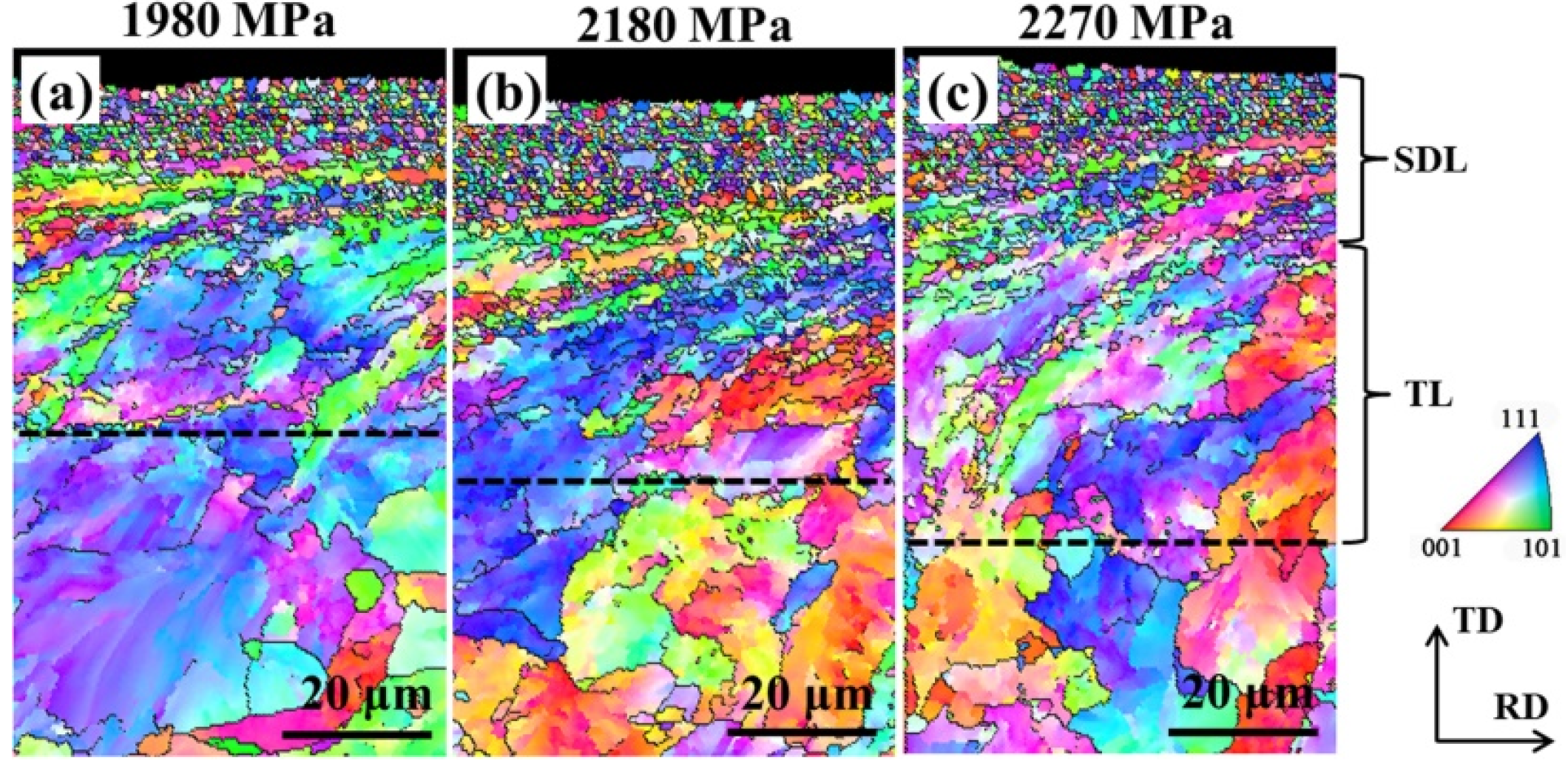
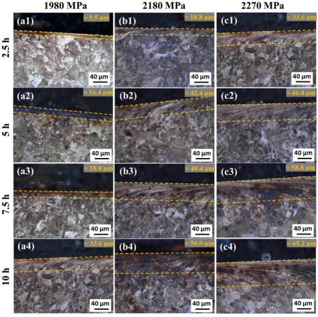
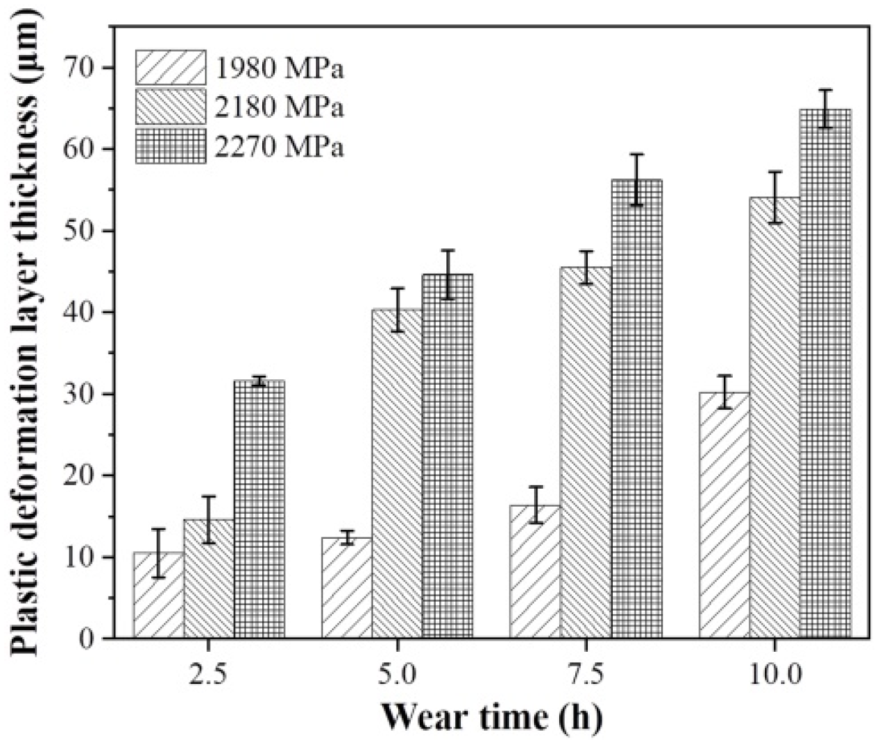
3.4. Plastic Deformation Layer

After wear tests, a plastic deformation layer usually forms near the worn surface. This phenomenon is normally unavoidable in contact pairs subjected to high contact stress wear [39]. The formation of plastic deformation layer has a significant impact on the wear rate and leads to a marked shift in the damage mechanism in the case of severe plastic deformation [40,41]. The EBSD method was adopted to analyze the grain characteristics within the plastic deformation layer of samples worn for 10 h, with the inverse pole figure (IPF) maps shown in Figure 10. The plastic deformation layer consists of a severely deformed layer (SDL) and a transition layer (TL) [34,42]. The EBSD-IPF maps indicate that the SDL mainly consisted of fragmented fine grains, while plastic flow microstructure presents in TL. Moreover, the rail samples subjected to greater contact stress exhibited a substantially thicker plastic deformation layer.
To explore the influences of contact stress and wear time on the thickness of the plastic deformation layer, the cross-sectional microstructure was observed using OM, as presented in Figure 11. Figure 12 presents the statistical variation in plastic deformation layer thickness with wear time and contact stress, based on five OM micrographs. Overall, the thickness of the plastic deformation layer increased with both wear time and contact stress. At a contact stress of 1980 MPa, a plastic deformation layer approximately 9.5 μm thick formed after 2.5 h of wear. However, after 10 h of wear, this layer thickened significantly to about 33.6 μm. Similar trends were observed at higher contact stresses of 2180 MPa and 2270 MPa, where the thickness of the plastic deformation layer also increased with wear time. Moreover, for a given wear time, the thickness of the plastic deformation layer increased with contact stress. Notably, at the highest contact stress of 2270 MPa, the plastic deformation layer reached a great thickness of 65.2 μm after 10 h of wear.
The variation of surface hardness with contact stress and wear time is shown in Figure 13a. It can be clearly observed that the surface hardness increased with both contact stress and wear time. Specifically, for a given contact stress, the longer the wear time, the higher the surface hardness; when the wear time was the same, the higher the contact stress, the higher the surface hardness. This increase in hardness near the worn surface was attributed to plastic deformation induced by the wear process. When contact stress was constant, extended wear times caused more plastic deformation, which in turn led to a greater accumulation of dislocations and consequently higher hardness [43,44]. Similarly, when wear time was constant, higher contact stresses enhanced work hardening on the surface of the rail samples, thereby increasing the hardness.
The hardening rate for each sample was determined using Equation (5):
k = (Hmeasured − Hinitial)/Hinitial
where k represents hardening rate, and Hmeasured and Hinitial represent the hardness after wear tests and initial hardness of rail samples, respectively. The variation of hardening rate with contact stress and wear time is illustrated in Figure 13b. It is evident that under all three contact stress conditions, the hardening rates of the rail samples increased as wear time increased. Furthermore, for a given wear time, a higher contact stress resulted in a higher hardening rate. Overall, both surface hardness and hardening rate exhibited a strong correlation with the thickness of the plastic deformation layer.
With the increasing load capacity of trains, rail manufacturers are continuously developing rail products with greater hardness. Therefore, in the future, it will be necessary to conduct wear performance tests on rails with higher hardness under greater contact stress conditions. This will provide rail manufacturers with assessments of harder rail wear performance. Additionally, rail wear is usually more severe in humid areas such as coastal regions and tunnels due to corrosive wear. Thus, studies on rail wear behavior in artificially simulated corrosive environments will also be a key focus of future studies.

4. Conclusions

In the present study, twin-disc sliding–rolling wear tests were conducted on U75VH pearlite heat-treated rail steel using high contact stress within the range from 1980 MPa to 2270 MPa for 10 h, followed by microstructure analyses using OM, SEM, 3D microscopy, EBSD, and hardness tests. The following conclusions can be drawn:
(1)
With increasing wear time, the crack length and depth increased significantly. Additionally, as contact stress increased, the energy available for crack propagation increased, making it easier for cracks to develop into the material at larger angles. This resulted in longer, deeper cracks with larger propagation angles and more severe fatigue wear, highlighting a significant stress concentration near the contact surface.
(2)
The wear weight loss increased with both wear time and contact stress. At a given contact stress, the wear rate increased with increasing wear time. The wear resistance increased with time and eventually tended to stabilize. Additionally, the wear rate of the rail samples showed a nearly linear increase as the contact stress increased.
(3)
As wear time and contact stress increased, the worn surface exhibited more pronounced spalling and extensive spalling pits. The wear degree of the rail sample surface increased significantly, leading to higher roughness. Moreover, the severity of adhesive and abrasive wear increased.
(4)
The thickness of the plastic deformation layer increased with increasing wear time. Moreover, at the same wear time, the thickness of the plastic deformation layer gradually increased with increasing contact stress. The surface hardness was dependent on the thickness of the plastic deformation layer.

Author Contributions

Conceptualization, G.C. and G.X.; methodology, G.C.; software, R.W.; validation, R.W. and G.C.; formal analysis, G.X.; investigation, R.W., N.X., L.S. and J.W.; resources, G.X.; data curation, R.W.; writing—original draft preparation, R.W.; writing—review and editing, G.C. and G.X.; visualization, R.W.; supervision, G.C. and G.X.; project administration, G.C. and G.X.; funding acquisition, G.C. All authors have read and agreed to the published version of the manuscript.

Funding

This research was funded by China Postdoctoral Science Foundation (No. 2022M722486) and Hubei Provincial Natural Science Foundation of China (No. 2024AFB264).

Data Availability Statement

The original contributions presented in this study are included in the article. Further inquiries can be directed to the corresponding authors.

Acknowledgments

The authors would like to thank Zhen Wang at the Analytical & Testing Center of Wuhan University of Science and Technology for the help on EBSD analyses.

Conflicts of Interest

The authors declare no conflict of interest.

Abbreviations

The following abbreviations are used in this manuscript:
OMOptical microscopy
SEMScanning electron microscope
EBSDElectron backscatter diffraction
TRIPTransformation induced plasticity
SDLSeverely deformed layer
TLTransition layer
IPFInverse pole figure

References

  1. Ramalho, A. Wear Modelling in Rail–Wheel Contact. Wear 2015, 330–331, 524–532. [Google Scholar] [CrossRef]
  2. Soleimani, H.; Moavenian, M. Tribological Aspects of Wheel–Rail Contact: A Review of Wear Mechanisms and Effective Factors on Rolling Contact Fatigue. Urban Rail Transit 2017, 3, 227–237. [Google Scholar] [CrossRef]
  3. Solano-Alvarez, W.; Bhadeshia, H.K.D.H. Steels for Rails. Prog. Mater. Sci. 2024, 146, 101313. [Google Scholar] [CrossRef]
  4. Chen, G.; Rahimi, R.; Xu, G.; Biermann, H.; Mola, J. Impact of Al Addition on Deformation Behavior of Fe–Cr–Ni–Mn–C Austenitic Stainless Steel. Mater. Sci. Eng. A 2020, 797, 140084. [Google Scholar] [CrossRef]
  5. Chen, G.; Xu, G.; Biermann, H.; Mola, J. Microstructure and Mechanical Properties of Co-Added and Al-Added Austenitic Stainless Steels. Mater. Sci. Eng. A 2022, 854, 143832. [Google Scholar] [CrossRef]
  6. Chen, G.; Hu, H.; Xu, G.; Tian, J.; Wan, X.; Wang, X. Optimizing Microstructure and Property by Ausforming in a Medium-Carbon Bainitic Steel. ISIJ Int. 2020, 60, 2007–2014. [Google Scholar] [CrossRef]
  7. Tian, J.; Wang, W.; Xu, G.; Wang, X.; Zhou, M.; Zurob, H. Microstructure and Properties of a Low Carbon Bainitic Steel Produced by Conventional and Inverted Two-Step Austempering Processes. Met. Mater. Int. 2023, 29, 1298–1310. [Google Scholar] [CrossRef]
  8. Adamczyk-Cieślak, B.; Koralnik, M.; Kuziak, R.; Majchrowicz, K.; Mizera, J. Studies of Bainitic Steel for Rail Applications Based on Carbide-Free, Low-Alloy Steel. Metall. Mater. Trans. A 2021, 52, 5429–5442. [Google Scholar] [CrossRef]
  9. Masoumi, M.; Tressia, G.; Centeno, D.M.A. Hélio Goldenstein Improving the Mechanical Properties and Wear Resistance of a Commercial Pearlitic Rail Steel Using a Two-Step Heat Treatment. Metall. Mater. Trans. A 2021, 52, 4888–4906. [Google Scholar] [CrossRef]
  10. Su, X.; Xu, G.; Zhu, M.; Zhang, Q.; Cai, F.; Liu, M. Investigation on the Interaction between Corrosion and Wear of U68CuCr Rail Steel with Different Corrosion Periods. Wear 2023, 516–517, 204598. [Google Scholar] [CrossRef]
  11. Fei, J.; Zhou, G.; Zhou, J.; Zhou, X.; Li, Z.; Zuo, D.; Wu, R. Research on the Effect of Pearlite Lamellar Spacing on Rolling Contact Wear Behavior of U75V Rail Steel. Metals 2023, 13, 237. [Google Scholar] [CrossRef]
  12. Xu, J.; Wang, P.; Wang, L.; Chen, R. Effects of Profile Wear on Wheel–Rail Contact Conditions and Dynamic Interaction of Vehicle and Turnout. Adv. Mech. Eng. 2016, 8, 1–14. [Google Scholar] [CrossRef]
  13. Wang, P.; Xu, J.; Xie, K.; Chen, R. Numerical Simulation of Rail Profiles Evolution in the Switch Panel of a Railway Turnout. Wear 2016, 366–367, 105–115. [Google Scholar] [CrossRef]
  14. Aquib Anis, M.; Srivastava, J.P.; Duhan, N.R.; Sarkar, P.K. Rolling Contact Fatigue and Wear in Rail Steels: An Overview. In Proceedings of the IOP Conference Series: Materials Science and Engineering, Melbourne, Australia, 15–16 September 2018; Volume 377, p. 012098. [Google Scholar]
  15. Wang, R.; Chen, G.; Xu, N.; Chen, Z.; Zhu, M.; Xu, G. Synergistic Behavior of Salt Spray Corrosion and Fatigue Wear of U75VH Pearlite Heat-Treated Rail. Mater. Today Commun. 2025, 47, 113059. [Google Scholar] [CrossRef]
  16. Seo, J.-W.; Jun, H.-K.; Kwon, S.-J.; Lee, D.-H. Rolling Contact Fatigue and Wear of Two Different Rail Steels under Rolling–Sliding Contact. Int. J. Fatigue 2016, 83, 184–194. [Google Scholar] [CrossRef]
  17. Fletcher, D.I.; Beynon, J.H. The Effect of Contact Load Reduction on the Fatigue Life of Pearlitic Rail Steel in Lubricated Rolling–Sliding Contact. Fatigue Fract. Eng. Mater. Struct. 2000, 23, 639–650. [Google Scholar] [CrossRef]
  18. Hu, Y.; Guo, L.C.; Maiorino, M.; Liu, J.P.; Ding, H.H.; Lewis, R.; Meli, E.; Rindi, A.; Liu, Q.Y.; Wang, W.J. Comparison of Wear and Rolling Contact Fatigue Behaviours of Bainitic and Pearlitic Rails under Various Rolling-Sliding Conditions. Wear 2020, 460–461, 203455. [Google Scholar] [CrossRef]
  19. Zhang, S.; Spiryagin, M.; Lin, Q.; Ding, H.; Wu, Q.; Guo, J.; Liu, Q.; Wang, W. Study on Wear and Rolling Contact Fatigue Behaviours of Defective Rail under Different Slip Ratio and Contact Stress Conditions. Tribol. Int. 2022, 169, 107491. [Google Scholar] [CrossRef]
  20. Wang, H.; Ding, H.; Zhang, S.; Shi, Z.; Meli, E.; Wang, W.; Lewis, R.; Liu, Q.; Zhou, Z. Quantitative Characterization of the Relationship between Wear and Rolling Contact Fatigue of Rail Material. Wear 2025, 578–579, 206169. [Google Scholar] [CrossRef]
  21. Taleff, E.M.; Syn, C.K.; Lesuer, D.R.; Sherby, O.D. Pearlite in Ultrahigh Carbon Steels: Heat Treatments and Mechanical Properties. Metall. Mater. Trans. A 1996, 27, 111–118. [Google Scholar] [CrossRef]
  22. Zhang, G.-H.; Chae, J.-Y.; Kim, K.-H.; Suh, D.W. Effects of Mn, Si and Cr Addition on the Dissolution and Coarsening of Pearlitic Cementite during Intercritical Austenitization in Fe-1mass%C Alloy. Mater. Charact. 2013, 81, 56–67. [Google Scholar] [CrossRef]
  23. Min, N.; Zhu, Y.; Fan, S.; Xiao, Y.; Zhou, L.; Li, W.; Zhao, S. Synergistic Effect of Alloying on the Strength and Ductility of High Carbon Pearlitic Steel. Metals 2023, 13, 1535. [Google Scholar] [CrossRef]
  24. Liu, J.; Guo, K.; Ma, H.; He, J.; Wang, J.; Zhang, C.; Wang, T.; Wang, Q. Microstructural Evolution and Tensile Properties of Nb-V-Ti-N Microalloyed Steel with Varying Nitrogen Contents. Metals 2025, 15, 266. [Google Scholar] [CrossRef]
  25. Wen, H.; Wang, Q.; Dou, Y.; Wang, Q.; Xu, X.; Wang, Q. Comparison of Strengthening Mechanism of the Nb, V, and Nb-V Micro-Alloyed High-Strength Bolt Steels Investigated by Microstructural Evolution and Strength Modeling. Metals 2024, 14, 1309. [Google Scholar] [CrossRef]
  26. Gao, Y. Research on Transient Wheel-Rail Friction Contact Behavior and Non-Uniform Wear in Turnout Switch Panel. Ph.D. Thesis, Southwest Jiaotong University, Chengdu, China, 2021. (In Chinese). [Google Scholar]
  27. Wu, Y.; Zhao, J.; Miao, H.; Zhang, X.; Wen, Z.; Xu, J.; Wang, P.; Kan, Q. 3D Rolling Contact Finite Element Analysis of High-Speed Railway Turnout Considering Ratchetting Effect. Eng. Fail. Anal. 2024, 160, 108171. [Google Scholar] [CrossRef]
  28. Burgelman, N.; Li, Z.; Dollevoet, R. A New Rolling Contact Method Applied to Conformal Contact and the Train–Turnout Interaction. Wear 2014, 321, 94–105. [Google Scholar] [CrossRef]
  29. Wang, W.J.; Wang, H.; Wang, H.Y.; Guo, J.; Liu, Q.Y.; Zhu, M.H.; Jin, X.S. Sub-Scale Simulation and Measurement of Railroad Wheel/Rail Adhesion under Dry and Wet Conditions. Wear 2013, 302, 1461–1467. [Google Scholar] [CrossRef]
  30. Archard, J.F. Contact and Rubbing of Flat Surfaces. J. Appl. Phys. 1953, 24, 981–988. [Google Scholar] [CrossRef]
  31. Andersson, J.; Almqvist, A.; Larsson, R. Numerical Simulation of a Wear Experiment. Wear 2011, 271, 2947–2952. [Google Scholar] [CrossRef]
  32. Hu, Y.; Wang, W.J.; Watson, M.; Six, K.; Al-Maliki, H.; Meierhofer, A.; Lewis, R. Wear of Driving versus Driven Discs in a Twin Disc Rolling-Sliding Test. Wear 2023, 512–513, 204528. [Google Scholar] [CrossRef]
  33. Liu, J. Experimental Research on Rolling Wear and Contact Fatigue Damage Behaviors of Wheel/Rail Materials. Ph.D. Thesis, Southwest Jiaotong University, Chengdu, China, 2016. (In Chinese). [Google Scholar]
  34. Li, J.; Zhou, Y.; Cheng, Z.; Wang, C.; Weng, Z.-Y. Evolution of Microscopic Characteristics of Rolling Contact Fatigue Coexisting with Wear of U75V Rail. Tribol. Int. 2023, 190, 109041. [Google Scholar] [CrossRef]
  35. Paris, P.C. A Rational Analytic Theory of Fatigue. Trends Eng. 1961, 13, 9–14. [Google Scholar]
  36. Mazzù, A.; Petrogalli, C.; Lancini, M.; Ghidini, A.; Faccoli, M. Effect of Wear on Surface Crack Propagation in Rail–Wheel Wet Contact. J. Mater. Eng. Perform. 2018, 27, 630–639. [Google Scholar] [CrossRef]
  37. Kráčalík, M.; Trummer, G.; Daves, W. Application of 2D Finite Element Analysis to Compare Cracking Behaviour in Twin-Disc Tests and Full Scale Wheel/Rail Experiments. Wear 2016, 346–347, 140–147. [Google Scholar] [CrossRef]
  38. Tosangthum, N.; Krataitong, R.; Wila, P.; Koiprasert, H.; Buncham, K.; Kansuwan, P.; Manonukul, A.; Sheppard, P. Dry Rolling-Sliding Wear Behavior of ER9 Wheel and R260 Rail Couple under Different Operating Conditions. Wear 2023, 518–519, 204636. [Google Scholar] [CrossRef]
  39. Liang, X.; Wei, X.; Li, Y.; Wang, M.; Liu, F. Effects of Lubricating Conditions on Wear Performance of U77MnCrH Rail. Metals 2024, 14, 414. [Google Scholar] [CrossRef]
  40. Ding, H.H.; Fu, Z.K.; Wang, W.J.; Guo, J.; Liu, Q.Y.; Zhu, M.H. Investigation on the Effect of Rotational Speed on Rolling Wear and Damage Behaviors of Wheel/Rail Materials. Wear 2015, 330–331, 563–570. [Google Scholar] [CrossRef]
  41. Gren, D.; Ahlström, J. Fatigue Crack Propagation on Uniaxial Loading of Biaxially Predeformed Pearlitic Rail Steel. Metals 2023, 13, 1726. [Google Scholar] [CrossRef]
  42. Zhou, T.; Xu, H.; Ma, X.; Xu, Z.; Zhao, H.; He, Y. A Novel Carbide-Free Bainitic Heavy-Haul Wheel Steel with an Excellent Wear-Resistance under Rolling-Sliding Condition. Metals 2023, 13, 202. [Google Scholar] [CrossRef]
  43. Molyneux-Berry, P.; Davis, C.; Bevan, A. The Influence of Wheel/Rail Contact Conditions on the Microstructure and Hardness of Railway Wheels. Sci. World J. 2014, 2014, 209752. [Google Scholar] [CrossRef]
  44. Sun, P.; Yang, J.; Zhu, A.; Hu, Z.; Wang, J.; Liu, F.; Wang, X. Experimental Study on the Effect of Solid Lubricants on Wheel Rail Contact Wear and Surface Hardness Evolution. Ind. Lubr. Tribol. 2023, 75, 904–910. [Google Scholar] [CrossRef]
Figure 1. Illustration for twin-disc sliding–rolling wear tests: (a) sample size; (b) schematic diagram of the twin-disc setup with load direction and contact zone highlighted.
Metals 15 00676 g001
Figure 3. Worn surface morphology of rail samples under the conditions with different contact stress and wear time: (a1a4) 1980 MPa; (b1b4) 2180 MPa; (c1c4) 2270 MPa; (a1c1) 2.5 h; (a2c2) 5 h; (a3c3) 7.5 h; (a4c4) 10 h.
Metals 15 00676 g003
Figure 4. Analyses for the worn surface morphology of the rail samples subjected to wear under a contact stress of 1980 MPa: (a) 2.5 h; (b) 5 h; (c) 7.5 h; (d) 10 h; (e) height profile corresponding to the regions marked with lines. The numbers marked for lines in (ad) correspond to the numbers of curves in (e).
Metals 15 00676 g004
Figure 5. Analyses for the worn surface morphology of the rail samples subjected to wear under a contact stress of 2180 MPa: (a) 2.5 h; (b) 5 h; (c) 7.5 h; (d) 10 h; (e) height profile corresponding to the regions marked with lines. The numbers marked for lines in (ad) correspond to the numbers of curves in (e).
Metals 15 00676 g005
Figure 6. Analyses for the worn surface morphology of the rail samples subjected to wear under a contact stress of 2270 MPa: (a) 2.5 h; (b) 5 h; (c) 7.5 h; (d) 10 h; (e) height profile corresponding to the regions marked with lines. The numbers marked for lines in (ad) correspond to the numbers of curves in (e).
Metals 15 00676 g006
Figure 7. Surface roughness of rail samples changing with contact stress and wear time. Error bars indicate mean difference.
Metals 15 00676 g007
Figure 8. Fatigue cracks near the surface of rail samples after wear tests with different conditions: (a1a4) 1980 MPa; (b1b4) 2180 MPa; (c1c4) 2270 MPa; (a1c1) 2.5 h; (a2c2) 5 h; (a3c3) 7.5 h; (a4c4) 10 h.
Metals 15 00676 g008
Figure 9. Analysis for cracks: (a) angles after 10 h of wear test under different contact stress; (b) relationship between crack length and number of cycles. Error bars in (b) indicate mean difference.
Metals 15 00676 g009
Figure 10. EBSD normal direction IPF maps of the plastic deformation layer after 10 h of wear under different contact stress: (a) 1980 MPa; (b) 2180 MPa; (c) 2270 MPa.
Metals 15 00676 g010
Figure 11. OM micrographs of plastic deformation layer: (a1a4) 1980 MPa; (b1b4) 2180 MPa; (c1c4) 2270 MPa; (a1c1) 2.5 h; (a2c2) 5 h; (a3c3) 7.5 h; (a4c4) 10 h.
Metals 15 00676 g011
Figure 12. Thickness of plastic deformation layer changing with contact stress and wear time. Error bars indicate mean difference.
Metals 15 00676 g012
Figure 13. Analyses on surface hardness: (a) hardness changing with contact stress and wear time; (b) hardening rate curves. Error bars in (a) indicate mean difference.
Metals 15 00676 g013
Table 1. Alloying composition of the experimental steels (wt.%).
SteelsCMnSiCrNiVTiFe
U75VH0.760.920.700.12/0.05/Bal.
Wheel steel0.540.790.340.190.0840.0070.003Bal.
Table 2. Statistical results of the fatigue cracks in rail samples. The errors represent mean difference.
Contact Stress (MPa)Wear
Time
(h)
Ave.
Length
(μm)
Max. Length (μm)Ave. Depth (μm)Max. Depth (μm)Ave.
Angle
(°)
Max.
Angle
(°)
19802.521.47 ± 16.0839.692.76 ± 0.503.2710.17 ± 4.5814.11
531.20 ± 6.2537.954.73 ± 2.387.2711.87 ± 5.0217.06
7.530.52 ± 6.7137.973.56 ± 1.174.737.47 ± 2.048.93
1048.85 ± 22.6963.097.13 ± 2.4910.006.02 ± 0.796.74
21802.524.20 ± 3.2727.854.24 ± 0.554.7210.28 ± 2.6013.17
535.87 ± 6.8141.657.90 ± 1.789.8013.44 ± 9.3423.26
7.536.77 ± 13.2451.426.28 ± 3.8310.2011.09 ± 2.4512.64
1043.18 ± 14.2457.455.23 ± 2.027.456.55 ± 2.299.04
22702.529.85 ± 11.5940.174.09 ± 0.965.0111.15 ± 5.3216.23
534.51 ± 8.2739.695.48 ± 2.748.6310.35 ± 4.4915.13
7.560.96 ± 49.68111.628.89 ± 5.7614.458.19 ± 4.3412.93
1097.92 ± 26.51128.2921.58 ± 9.2931.1011.20 ± 6.2816.33
Disclaimer/Publisher’s Note: The statements, opinions and data contained in all publications are solely those of the individual author(s) and contributor(s) and not of MDPI and/or the editor(s). MDPI and/or the editor(s) disclaim responsibility for any injury to people or property resulting from any ideas, methods, instructions or products referred to in the content.

