Abstract
This paper presents a systematic analysis of the solid products formed during the cathodic decomposition of chalcopyrite using the acetic acid system. The reduction of chalcopyrite was assessed using different electrochemical and surface characterization techniques. The effect of multiple cathodic polarizations of chalcopyrite immersed in acetic acid was evaluated on the formation of less refractory copper species through the interaction of chalcopyrite with monoatomic hydrogen. The reduction products obtained were characterized by the FESEM/EDS techniques. The results revealed that the iron content in the chalcopyrite lattice was continuously decreased and released into the acetic acid solution when the polarization cycles were increased from 1 to 11 starting from OCP to −2.2 V vs. SHE. The chemical analyses revealed that iron released into the solution corresponds to 0.085 and 1.95 mg/L for 1 and 11 cycles, respectively. The open circuit potential (OCP) measurements of the solid products were shifted to more cathodic potentials than that of chalcopyrite, confirming the possibility to form less refractory species in this weak organic acid. Finally, the FESEM-EDS and XRD analyses showed that chalcopyrite refractoriness decreased, producing Cu, Cu2S, CuS, CuO, and C4H6CuO4H2O species depending on the applied energetic condition.
1. Introduction
Ninety percent of global copper resources are sulfide ores, which are mainly composed of covellite (CuS), chalcocite (Cu2S), chalcopyrite (CuFeS2), and bornite (Cu5FeS4) [1]. Chalcopyrite is considered the most important source of copper. This mineral is highly refractory to conventional hydrometallurgical systems; therefore, in recent decades scientists and engineers have studied the feasibility of implementing different hydrometallurgical routes for copper recovery as an alternative to the pyrometallurgical systems [2].
Hydrometallurgical systems are mainly divided into oxidative and reductive processes. In the case of the oxidative processes, chalcopyrite dissolution is hindered due to a passivation phenomenon [3,4,5,6,7,8,9,10,11,12,13,14,15,16]. The nature of the passivating film formed during chalcopyrite oxidation has been continuously discussed by several researchers; e.g., in 1969, Burkin [3] suggested that the passivating film is composed of bimetallic sulfides that have different structure and chemical properties, but with the same semiconducting properties. On the other hand, Ammou-Chokroum et al. [4] suggest that passivation is caused by the formation of a low-solubility polysulfide. Muñoz et al. [5] established that the dissolution of chalcopyrite is limited due to the formation of an elemental sulfur layer.
Several researchers have studied alternative hydrometallurgical processes for copper recovery to avoid or decrease the passivation of chalcopyrite [17,18,19]. In this sense, conventional direct electrolytic methods have been described by Dahen and Allanore [20]. Dreisinger and Abed [21] also studied the cathodic decomposition of chalcopyrite using metallic iron as a reducing agent, the authors concluding that it is possible to transform chalcopyrite to less refractory phases (chalcocite) due to a proton transport-based mechanism.
On the other hand, researchers have also assessed the chalcopyrite electro-reduction in perchloric acid solutions at pH~0, and applying more cathodic potentials than −0.3 V vs. SHE, the results revealed that chalcopyrite can be electro-reduced to bornite, chalcocite, and elemental copper [22] according to Equations (1)–(3):
5CuFeS2 + 12H+ + e− → Cu5FeS4 + 4Fe2+ + 6H2S
2CuFeS2 + 6H+ + 2e− → Cu2S + 3H2S + 2Fe2+
Cu2S + 2H+ + 2e− → 2Cu0 + H2S
The hydrogen evolution reaction (HER) also takes place during the chalcopyrite electro-reduction processes. This classical electrochemical reaction has been studied by different researchers [23,24,25,26]. The evolution of molecular hydrogen is dependent on the type of molecules present in solution [27]. Some researchers reported the evolution of molecular hydrogen from free hydrogen ions or water molecules. However, other water-soluble molecules can be a source of hydrogen atoms, e.g., weak organic acids, where the proton is not dissociated. Martínez-Gómez et al. [28] proposed another reaction mechanism for the electrolytic reduction of chalcopyrite in sulfuric acid. The authors proposed that the reduction of chalcopyrite is carried out by the formation of monoatomic hydrogen (Equation (4)), and this is responsible for the reduction process of chalcopyrite to chalcocite according to Equation (5):
H+ + e− → H·
CuFeS2 + 2H+ + H· → ½ Cu2S + 3/2H2S + 2Fe2+
Subsequently, chalcocite can be electro-reduced to metallic copper, according to reaction shown in Equation (3) [29].
On the other hand, Martínez-Gómez et al. [28] reported that the electro-assisted reduction kinetics of chalcopyrite is significantly hindered in sulfuric acid solutions. When the pulp density is increased above 10 g/L, such a decrease in chalcopyrite reduction kinetics was attributed to the formation of an elemental sulfur layer that passivates the reduction process. This reveals that hydrometallurgical reductive processes of chalcopyrite are also susceptible to passivation. Martínez-Gómez et al. [28] proposed a mechanistic approach for chalcopyrite passivation during the electro-assisted reductive leaching in sulfuric acid; i.e., when the sulfur contained in the hydrogen sulfide molecules generated during the reduction of chalcopyrite interacts with the sulfuric acid producing elemental sulfur. This result reveals the importance of evaluating from an electrochemical viewpoint a novel reductive leaching system that does not contain oxidizing ions such as sulfate inhibiting the in situ oxidation of hydrogen sulfide to elemental sulfur.
In previous work, Jasso-Recio et al. [30] proposed to use a less aggressive acid, i.e., acetic acid, to develop an alternative eco-friendly hydrometallurgical process that allows the reduction of chalcopyrite using electricity. The authors found that the rate determining step of the chalcopyrite reduction in 3 M acetic acid corresponds to the formation of monoatomic hydrogen from the direct electro-reduction of acetic acid molecules with an apparent reaction order of 1. It was also found that chalcopyrite can be transformed to less refractory copper sulfides, tenorite and cuprite species using 11 cycles of polarization. As can be seen, it can be interesting to improve the understanding of the reaction mechanism in this recently proposed system using different polarization cycles. Therefore, this paper presents a systematic study regarding the microstructural characterization of the solid products that can be produced in different energetic conditions (polarization cycles, from 1 to 11) using the acetic acid-water novel system. This information can be employed in the future to develop an electrolytic system able to recover copper from chalcopyrite in a sustainable manner.
2. Materials and Methods
2.1. Materials
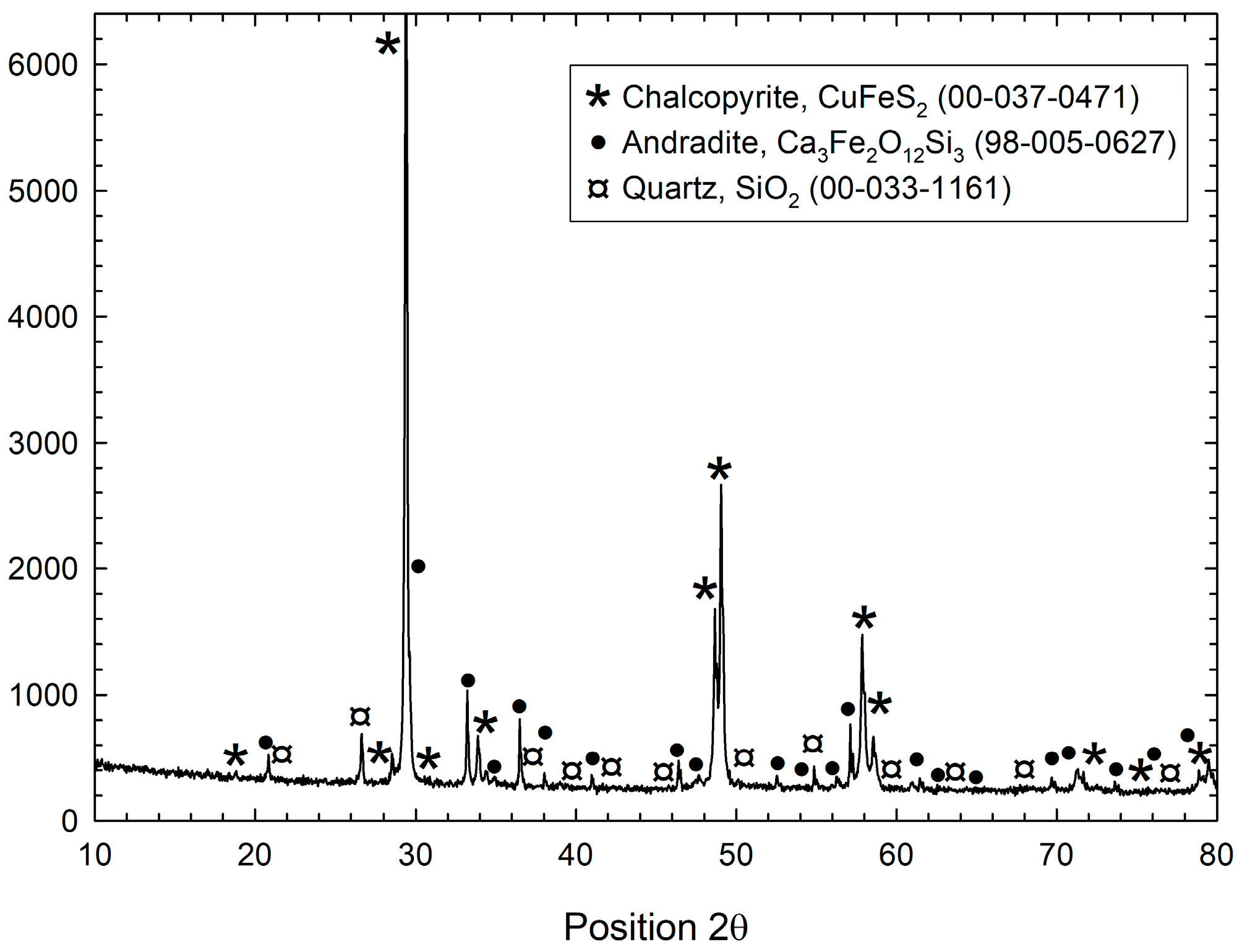
The chalcopyrite mineral used in this research was obtained at Concepcion del Oro, Zacatecas, Mexico and was cut and mounted in Teflon tubes to construct working electrodes with an active surface area of 35 mm2. Figure 1 shows the X-ray diffraction pattern of the chalcopyrite sample, which reveals that the mineral was mainly composed of chalcopyrite with some traces of quartz (SiO2) and andradite (Ca3Fe2O12Si3).
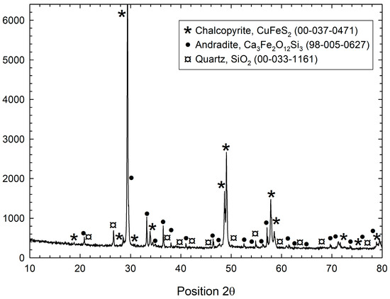
Figure 1.
X-ray diffraction pattern of the chalcopyrite electrode used in this research.
2.2. Electrochemical Tests
All electrochemical tests were carried out in a conventional 3-electrode electrochemical cell, which consisted of a working electrode (CuFeS2), a reference electrode (Ag/AgCl) immersed in a KCl solution contained in the Luggin capillary, and a graphite rod (Alfa Aesar, 99.999%, (USA) used as a counter electrode. The electrodes were connected to a potentiostat/galvanostat (Versastat 4–400, PAR, Shoreview, MN, USA).
The surface of the working electrode was metallographically prepared and renewed for each experiment. Coarse and fine grit (180–2400) silicon carbide sandpaper was used for the preparation, and the chalcopyrite surface was subsequently polished using 3 and 1 μm diamond paste until a mirror-like finish was obtained. Finally, the electrode was placed in an ultrasonic bath using ethanol for 10 min to remove the diamond paste and/or residual silicon carbide particles.
The effect of multiple cathodic polarizations of chalcopyrite was evaluated in 3 M acetic acid from open circuit potential (OCP) towards the cathodic direction (−2.2 V vs. SHE) at a scan rate of 0.02 V/s and 25 °C without stirring. The chalcopyrite electrode was polarized from 1 to 33 cycles. In order to evaluate the efficiency of the cathodic reduction of chalcopyrite, dissolved iron was quantified at different polarization cycles, using the atomic absorption spectroscopy technique (Thermo Fisher Scientific, ICE 3300, Waltham, MA, USA). It is also important to mention that OCP was recorded at the beginning of each polarization cycle.
2.3. Characterization of the Solid Products Formed
The morphology and chemical composition of some solid products formed on the chalcopyrite electrode in acetic acid were characterized by the FESEM and EDS techniques (Jeol, JSM-7800-F Prime, Tokyo, Japan) and the X-ray diffraction technique (Brunker, D8 Advance, Karlsruhe, Germany).
3. Results and Discussion
3.1. Effect of Multiple Cathodic Polarizations on Chalcopyrite Reduction
It has recently been reported that chalcopyrite can be electroreduced using acetic acid as a leaching medium. When chalcopyrite was polarized from OCP to −2.2 V vs. SHE, a solid product with the characteristic colors of bornite was observed. It was also reported that chalcopyrite reduction involves the release of iron from the chalcopyrite lattice into the acetic acid solution [30].
In order to improve our understanding of the reduction mechanism of chalcopyrite to different copper sulfide species and metallic copper, it was decided to perform multiple cathodic polarizations (1–11 cycles) using the chalcopyrite electrode; i.e., linear voltammetries were recorded from OCP to −2.2 V vs. SHE using 3 M acetic acid. It is worth mentioning that a previous work revealed the possibility of obtaining the highest cathodic current density with 3M acetic acid [30].
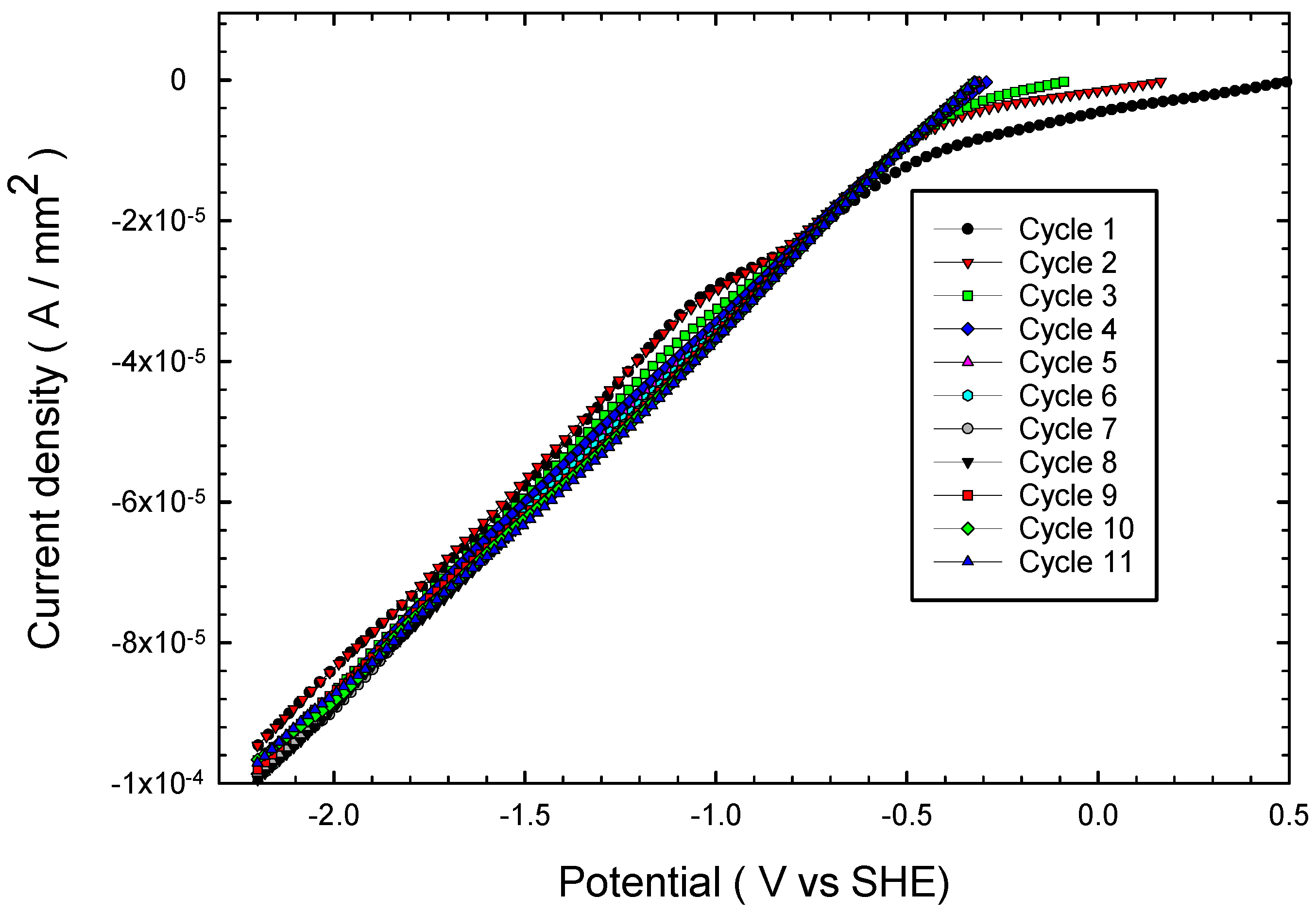
Figure 2 shows the cathodic polarizations carried out successively (1–11 cycles) from OCP up to a cathodic potential of −2.2 V vs. SHE without stirring. As can be observed, when the chalcopyrite electrode was polarized from OCP to −2.2 V vs. SHE, the cathodic current was increased. Such increase in the cathodic current is related to an enhancement in chalcopyrite reduction, according to Jasso-Recio et al. [30]. It is interesting to observe that cathodic current density was continuously decreased from OCP to −0.5 V vs. SHE (see cycles 1, 2 and 3 in Figure 2). However, when chalcopyrite was polarized from −0.5 V vs. SHE to −2.2 V vs. SHE, the cathodic current density was practically the same in all polarization cycles (see cycles 1 to 11).

Figure 2.
Multiple cathodic linear voltammetries for chalcopyrite from OCP up to −2.2 V vs. SHE in 3 M acetic acid at 20 mV/s and 25 °C without stirring.
On the other hand, when a chalcopyrite electrode was continuously polarized during the different cycles (Figure 2 and Figure 3), the OCP was modified towards more cathodic potentials than that for the OCP measured at the first polarization cycle. Figure 3 illustrates the OCP recorded in polarization tests of Figure 2; i.e., the OCP corresponded to ~0.5 and ~−0.3 V vs. SHE for cycle 1 and 11, respectively. This phenomenon can be related to the formation of a more reduced species on the chalcopyrite surface when the chalcopyrite electrode is continuously polarized from cycle 1 to 11. However, when chalcopyrite was polarized from cycle 4 to 11, it was possible to observe that OCP attained a pseudo-stationary value (−0.3 V vs. SHE). This reveals that chalcopyrite can be reduced to a species with an OCP of −0.3 V vs. SHE, approximately (Figure 3).
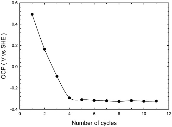
Figure 3.
OCP evolution with respect to the number of cathodic polarization cycles shown in Figure 2.
Although OCP was not further modified at the third and fourth cycle, it is interesting to observe in Figure 2 that an electrochemical reaction was still activated, in this case related to the formation of monoatomic hydrogen (reducing agent) from undissociated acetic acid and the chalcopyrite reduction, which is consistent with Jasso-Recio et al. [30]; i.e., this result reveals that chalcopyrite passivation in this system was inhibited. In order to verify this, the liquor solutions obtained at the different cycles (1–11 cycles) were analyzed using the atomic absorption spectroscopy technique. The results are shown in Table 1, where it is possible to observe that the iron content released into the solution increased as the number of cycles increased from 1 to 11 (the iron content shown in Table 1 corresponds to an area of ≈35 mm2 of chalcopyrite); i.e., the iron released into the solution corresponded to 0.085 and 1.95 mg/L for cycle 1 and 11, respectively. The increase in iron concentration in solution reveals the occurrence of chalcopyrite reduction to less refractory copper phases.

Table 1.
Dissolution of iron at different polarization cycles shown in Figure 1.
In order to assess the evolution of the solid products formed and their chemical composition, six chalcopyrite electrodes were used, which were labeled as M1, M2, M3, M4, M5, and M6 for the tests carried out at 1, 3, 5, 7, 9, and 11 polarization cycles, respectively.
Figure 4 shows the evolution of the product formed on the surface of chalcopyrite polarized at different cycles (M1–M6). As can be seen, when the number of cycles increased, the surface turned dark; i.e., the chalcopyrite electrode presented the characteristic colors of bornite at cycle 1 (see Figure 4a), while the surface of the chalcopyrite electrode turned dark at cycle 11 (see Figure 4f), which indicates that the product formed no longer corresponded to bornite. In order to elucidate the identity of the different solid products formed, it was decided to employ the FESEM/EDS techniques, as shown in the next section.
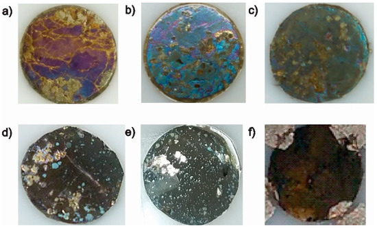
Figure 4.
Comparison of the layer formed on a chalcopyrite electrode subjected to different multiple cathodic polarizations starting from the OCP up to −2.2 V vs. SHE with 3 M acetic acid: (a) cycle 1, (b) cycle 3, (c) cycle 5, (d) cycle 7, (e) cycle 9, and (f) cycle 11.
3.2. Characterization of the Solid Products Formed During Different Polarization Cycles Using Field Emission Scanning Electron Microscopy
3.2.1. Solid Products Formed During 1, 3, and 5 Polarization Cycles
The characterization of the solid product obtained at cycle 1 (M1), which corresponds to 1 cathodic polarization of chalcopyrite from OCP to −2.2 V vs. SHE in 3 M acetic acid, was reported in previous studies [30]. Based on the content of Cu, Fe, S, and the colors of the formed layer (purple, pink, and blue), it was inferred that bornite is produced during the first polarization cycle.
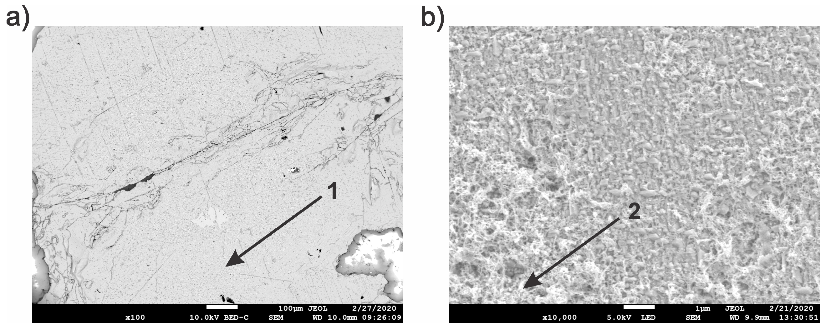
The layer formed on the chalcopyrite electrode after three cathodic polarizations (M2) is shown in Figure 4b. As can be seen, the purple shades decreased while the blue layer predominated with some small black areas. Figure 5a illustrates the micrograph of this layer at 100×, where it seems that the layer is homogeneous (zone 1). However, when this sample was inspected at higher magnifications, i.e., 7500×, it was possible to observe a second phase on the chalcopyrite surface (spongy zone), which is shown in Figure 5b (zone 2). This second phase was only present in small proportions in some zones.
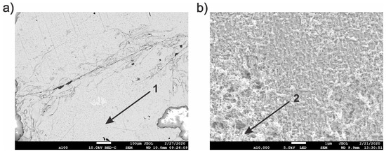
Figure 5.
FESEM characterization of the bluish layer formed on the chalcopyrite electrode (M2) at different magnifications: (a) 100× and (b) 10,000×.
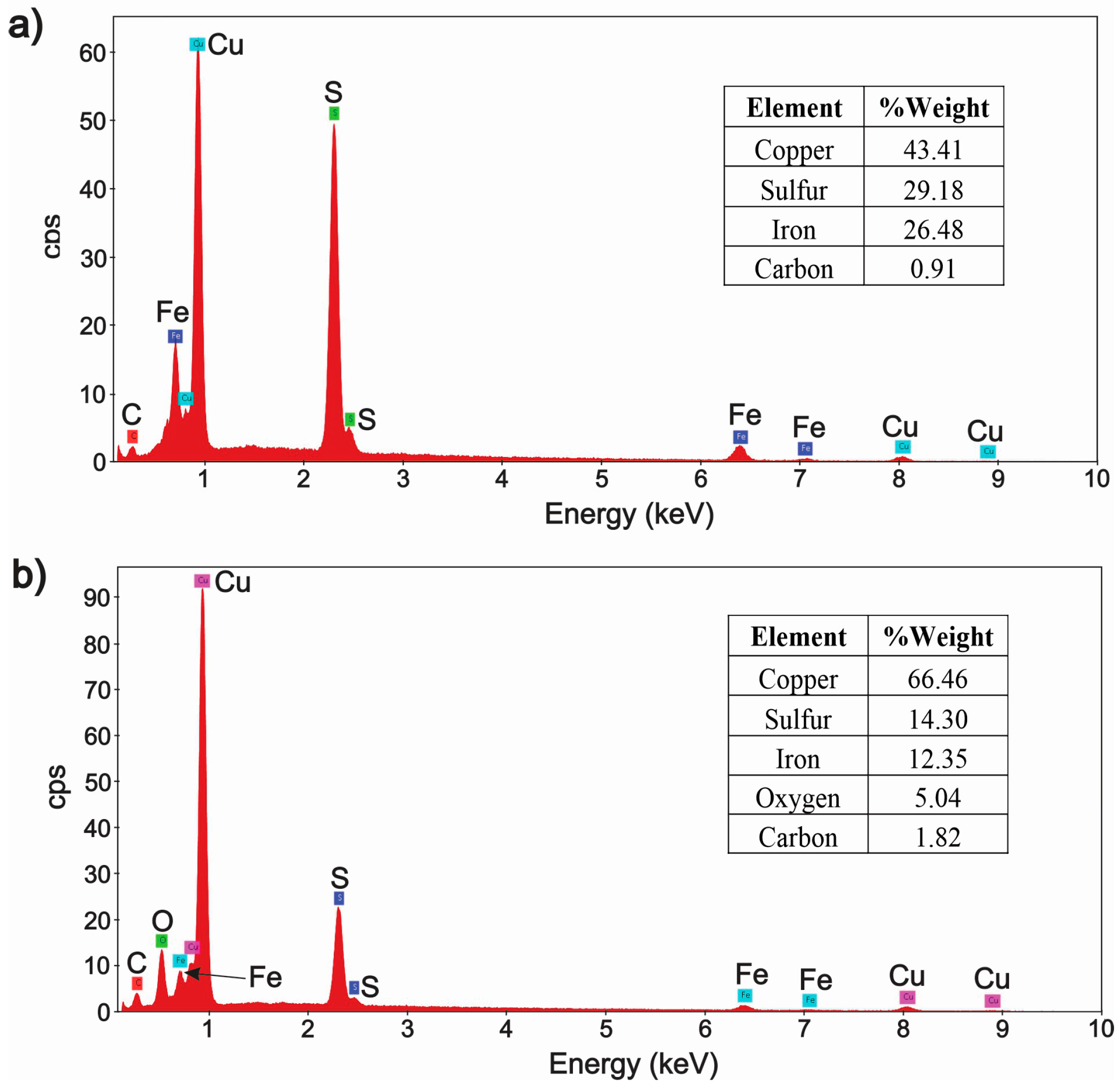
As can be noted in the EDS analysis of Figure 6, the solid product observed at zone 1 of Figure 5 corresponded to bornite. As regards zone 2 of Figure 5, the EDS analysis of Figure 6 revealed that the solid product was mainly composed of copper and sulfur, which could correspond to a copper sulfide species (chalcocite). However, the EDS analysis of Figure 6b also shows the presence of oxygen and copper, which reveals the possibility of producing a mixture of chalcocite and copper oxides; this can be related to the fact that in Figure 6b there is a lower amount of iron and sulfur in the polarized chalcopyrite than in the fresh chalcopyrite (characterization shown by Jasso-Recio et al. [30]).
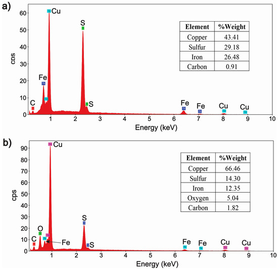
Based on these results, the formation of bornite and chalcocite can occur from the interaction of chalcopyrite with monoatomic hydrogen (produced from undissociated acetic acid), according to the following proposed reactions:
CH3COOH + e− → H. + CH3COO−
5CuFeS2 + 4H + 8H+ → Cu5FeS4 + 4Fe2+ + 6H2S
2Cu5FeS4 + 2H + 4H+ → 5Cu2S + 2Fe2+ + 3H2S
Based on results shown in Figure 5 and Figure 6, it is possible to observe that the main difference between the two zones of Figure 5 (1 and 2) is related to the content of iron and sulfur, which is higher in product of zone 1 than in the spongy zone 2. As regards the solid product formed on the chalcopyrite electrode subjected to 5 cathodic polarizations (M3), it is possible to observe in Figure 4c that the layer formed presented a predominating black zone with some small blue zones, which could be related to a mixture of chalcocite and bornite, respectively. This was verified in the analysis carried out with the FESEM/EDS techniques shown in Figure 7.
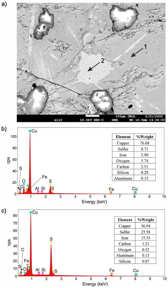
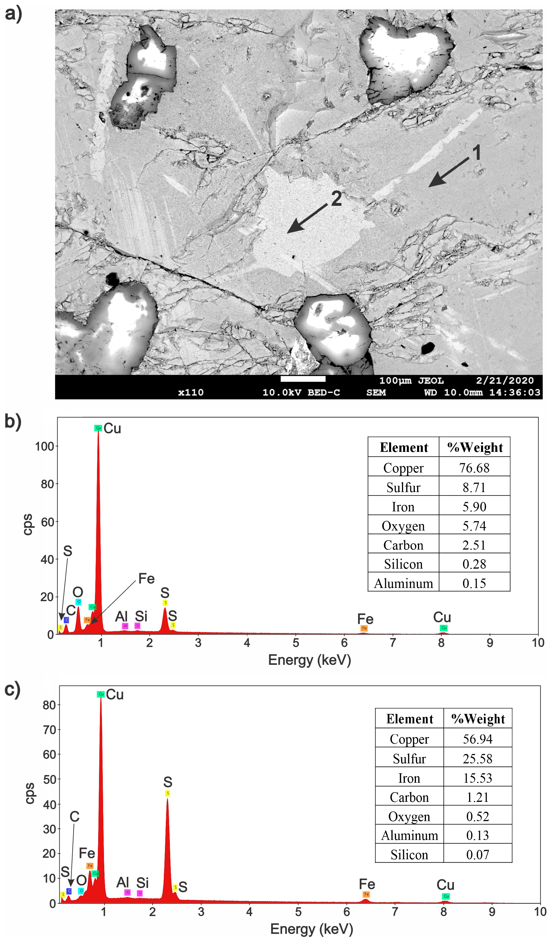
Figure 7.
(a) Micrograph obtained with the FESEM for the layer formed on the chalcopyrite electrode (M3) at 110×. (b) Qualitative and semi-quantitative analysis corresponding to zone 1 performed in a micro-area at 5000×. (c) Qualitative and semi-quantitative analysis corresponding to zone 2.
Figure 7a shows the micrograph corresponding to M3, where two different colors can be seen. These are related to a different chemical composition; i.e., zone 1 and zone 2 correspond to the black product and blue product shown in Figure 4c, respectively. The EDS analysis shown in Figure 7b,c revealed that the solid product of zone 1 was predominantly composed of a mixture of chalcocite and copper oxide species, while zone 2 showed the presence of Cu, Fe, and S, which could be related to bornite (this is consistent with the blue color shown in Figure 4c). Furthermore, it is interesting to emphasize that the amount of iron and sulfur present in zone 2 was much lower than that observed by Jasso-Recio et al. [30] for the fresh chalcopyrite substrate.
It is important to mention that the phases shown in zone 1 and 2 of sample M3 are the same as those found in M2. However, the amount of these mineral phases is different in both samples; i.e., in M2 (which corresponded to chalcopyrite polarized during three cycles) the matrix was composed of bornite and only at high magnifications were some small zones of copper sulfide and/or copper oxide found, while in M3 (which corresponded to chalcopyrite polarized during five cycles) the matrix was mainly composed of copper sulfide and/or copper oxide species with some discrete zones related to the presence of bornite.
As mentioned before, the spongy morphology was observed when the product layer contained copper sulfide and copper oxides, as shown in Figure 5b. In order to confirm this observation, Figure 8a,b show a comparison between two micrographs obtained at the same magnification (7500×) for samples M2 (chalcopyrite subjected to three polarization cycles) and M3 (chalcopyrite polarized during five cycles), respectively. As can be seen, the spongy zone covers almost the entire surface of M3, while in the case of M2 only a small area was observed at this magnification (see arrow in Figure 8a). This result confirms that the extent of chalcopyrite cathodic decomposition to copper sulfide species was higher in the system polarized during five cycles than that with three polarization cycles.
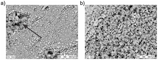
Figure 8.
Micrographs obtained in FESEM at 7500× for the layers formed in (a) M2 (three polarization cycles) and (b) M3 (five polarization cycles).
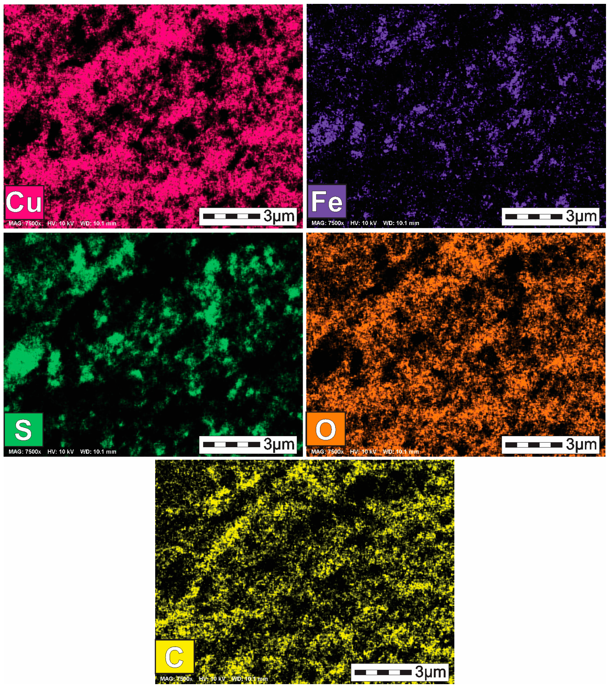
In order to complement the characterization of solid phases formed at the spongy zone of sample M3 (Figure 8b), an elemental mapping was carried out for this sample. Figure 9 illustrates the elemental mapping carried out for M3 at 7500×; the zone corresponding to bornite in the upper left corner is associated with copper, iron, sulfur, and a small amount of oxygen, while the predominant spongy zone is mainly composed of copper, oxygen, and dispersed sulfur, which confirms the presence of a mixture of copper sulfide and copper oxide species. It is worth mentioning that the presence of copper oxides was also observed by Martínez-Gómez et al. [28,31] when chalcopyrite was electro-reduced in sulfuric and hydrochloric acid. The authors demonstrated in the case of these systems that metallic copper was produced in the electrolytic cell, and this could be oxidized to copper oxides when it was contact with air. This mechanism could also occur in the acetic acid system; i.e., metallic copper can be formed in the electrolytic cell through the interaction of chalcocite with monatomic hydrogen (Equation (9)), followed by the oxidation of metallic copper with oxygen when it is withdrawn from the electrolytic cell.
Cu2S + 2H → 2Cu0 + H2S

Figure 9.
Elemental mapping for M3 at 7500×.
3.2.2. Solid Products Formed During Seven Polarization Cycles
As observed in previous sections, chalcopyrite can be decomposed to less refractory species (copper sulfides and copper oxides). The formation of these species is favored when the chalcopyrite electrode is polarized during five cycles. It can be interesting to determine the solid products that can be produced when chalcopyrite electrode is polarized during seven cycles. Figure 4d shows that chalcopyrite subjected to seven polarization cycles (M4) presented a black color layer with very few blue zones. It was suggested that the solid product corresponded to a mixture of chalcocite (the dark layer), and bornite (small blue zones). However, this must be verified using the FESEM-EDS characterization.
Figure 10a shows the micrograph obtained for M4, where two zones with different colors can be seen, which reveals the formation of two different phases; i.e., zone 1 corresponds to the black layer of Figure 4d and zone 2 to the small blue zones of Figure 4d. The EDS analysis of zone 1 and 2 is presented in Figure 10b,c. As can be observed, zone 1 can be associated with a mixture of chalcocite and copper oxides species, while zone 2 is predominantly composed of Cu, Fe, and S, which are characteristic of bornite. A comparison of solid products formed in M4 and M3 reveals that the same copper species were produced at seven and five polarization cycles, respectively. However, the extent of chalcopyrite reduction was higher in the system operated at seven polarization cycles than that observed with five polarization cycles. This is consistent with the chalcopyritic iron released into the solution. Table 1 shows that the iron released corresponded to 0.82 and 1.4 ppm for the systems operated at five and seven polarization cycles (samples M3 and M4, respectively). As mentioned before, an increase in the released iron is related to an enhancement of the chalcopyrite reduction extent.
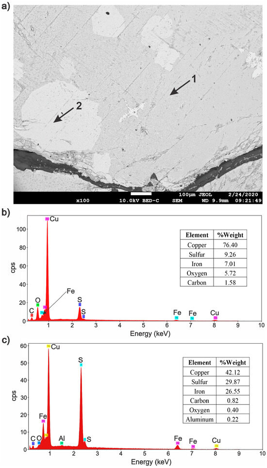
Figure 10.
(a) Micrograph obtained with FESEM for the layer formed on the chalcopyrite electrode (M4) at 100×. (b) Qualitative and semi-quantitative analysis corresponding to zone 1 performed in a micro-area at 5000× and (c) qualitative and semi-quantitative analysis corresponding to zone 2.
The main difference between sample M4 (which corresponded to seven polarization cycles) and sample M3 (which corresponded to five polarization cycles) was the amount of bornite; i.e., bornite was considerably lower in M4 than that found for sample M3.
In a similar way to the previous sample M3, sample M4 was carefully inspected using the FESEM technique at 7500×, where it was possible to find two zones (see micrograph of Figure 11); i.e., a predominant spongy zone and the small bornite zone (blue zone observed in the left side of micrograph of Figure 11). As mentioned in the characterization of M3, the spongy morphology can be related to the presence of copper sulfides and copper oxides species. In order to confirm this hypothesis, an elemental mapping of this micrograph was carried out in Figure 11.
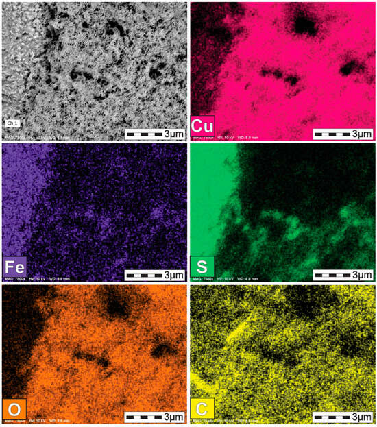
Figure 11.
Map of elements for M4 (chalcopyrite electrode polarized during seven cycles) at 7500×.
The elemental mapping of Figure 11 revealed the presence of copper, iron, and sulfur in both phases; however, it was possible to distinguish that the blue zone (left side of micrograph of Figure 11) had a higher amount of sulfur and iron, as well as a lower amount of copper than that of the spongy zone, while the spongy zone was enriched in copper and was mainly associated with oxygen and sulfur.
Although the spongy zone still had sulfur and iron, the amount of these elements was lower than that of the blue zone. This can be clearly observed in the EDS shown in Figure 10b,c. As regards the carbon element, it appeared all over the surface, but with a low amount, as shown in EDS analyses of Figure 10b,c; i.e., the presence of carbon was not related to the solid products formed (copper sulfides, copper oxides, and bornite).
3.2.3. Solid Products Formed During Nine Polarization Cycles
As shown in Figure 4e, when chalcopyrite was polarized during nine cycles (M5), the solid product was totally black, which can be related to chalcocite species. Furthermore, Table 1 showed that iron released into the bulk solution corresponded to 1.7 ppm, which was higher than that measured for sample M4 at seven polarization cycles, revealing that chalcopyrite reduction conversion was increased when the polarization cycles increased from seven to nine. The identity of the solid product formed in sample M5 had to be elucidated using the FESEM-EDS techniques.
Figure 12 illustrates the micrograph corresponding to M5, where two different colors can be seen (zones 1 and 2). It is also possible to observe small acicular zones which are finely distributed in some areas of the surface, revealing the formation of a third phase (zone 3).
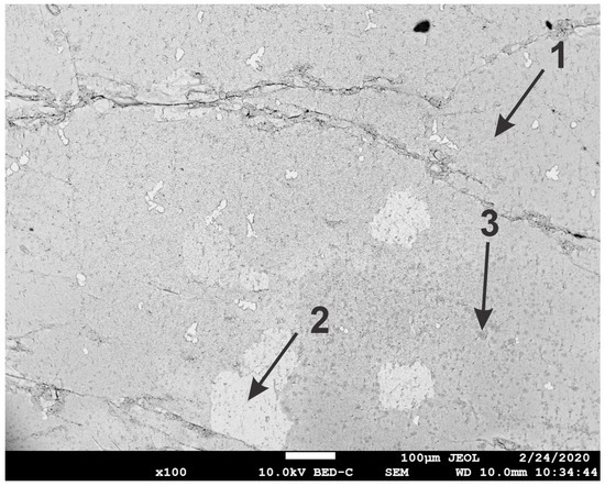
Figure 12.
Micrograph obtained with the FESEM for the layer formed on the chalcopyrite electrode polarized during nine cycles (M5) at 100×.
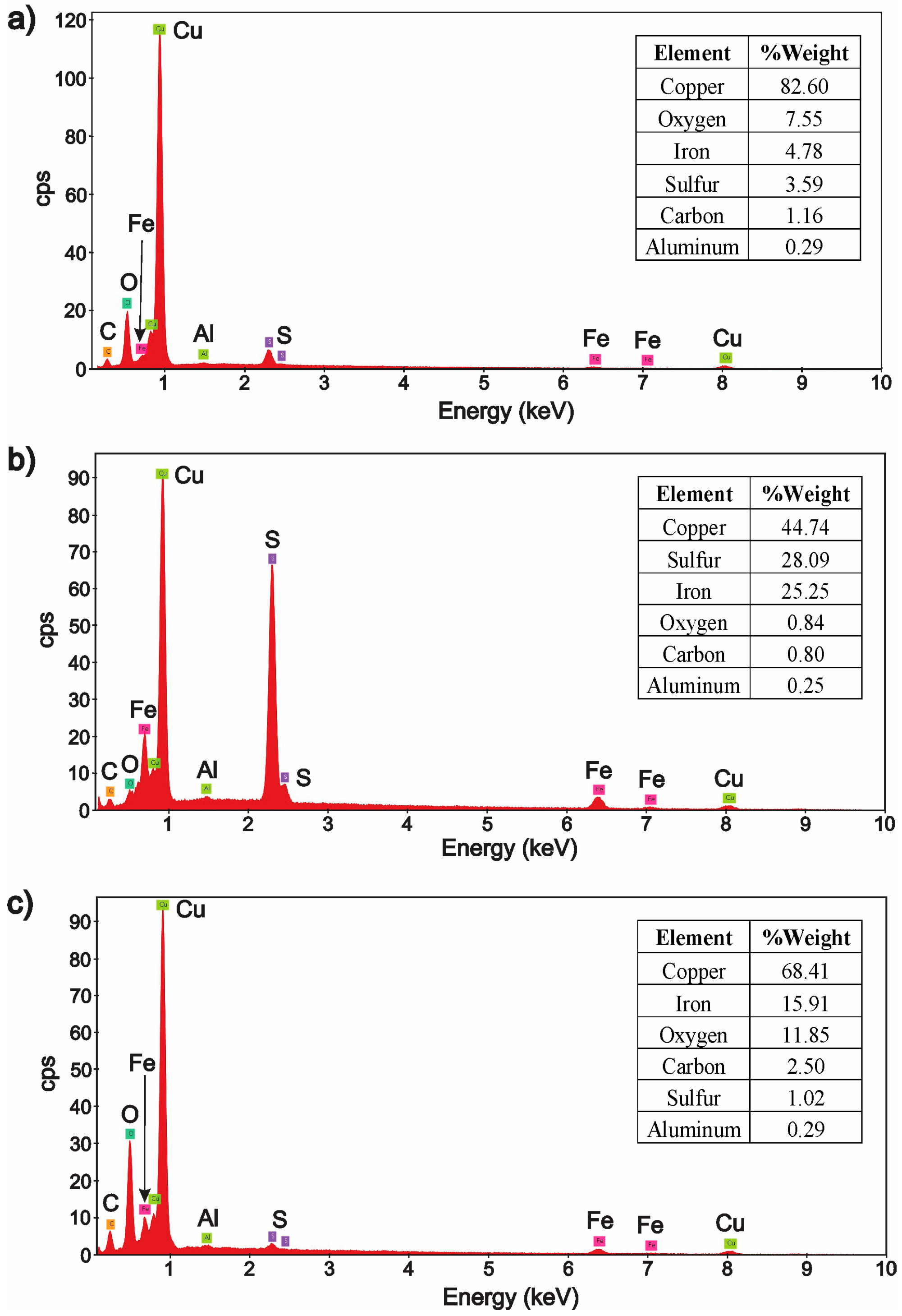
The local chemical composition of the different products formed in zones 1, 2, and 3 are displayed in Figure 13. As can be noted in Figure 13a, zone 1 mainly corresponded to copper oxides species with a small amount of chalcocite (this is consistent with the fact that the amount of sulfur was considerably decreased). In the case of zone 2, Figure 13b reveals that the reduction product was mainly composed of Cu, Fe, and S, which could correspond to the remaining bornite, while zone 3 (Figure 13c) was predominantly composed of copper, iron, oxygen, and carbon, which could correspond to a mixture of copper acetate with iron acetate species.
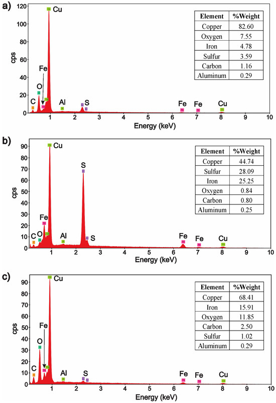
Figure 13.
Qualitative and semi-quantitative analysis obtained by FESEM/EDS for (a) zone 1 performed in a micro-area at 5000×, (b) zone 2 performed in a micro-area at 5000× and (c) zone 3.
3.2.4. Solid Products Formed During 11 and 33 Polarization Cycles
When chalcopyrite was consecutively subjected to 11 cathodic polarizations (M6), Figure 4f shows that the solid product presented black, brown, and blue areas. These colors can probably be related to the formation of chalcocite, copper oxides, and bornite species. It is worth mentioning that Jasso-Recio et al. [30] presented the X-ray characterization of predominating products obtained when chalcopyrite was polarized during 11 cycles. The authors reported the formation of CuO, CuS, Cu2S, and Cu.
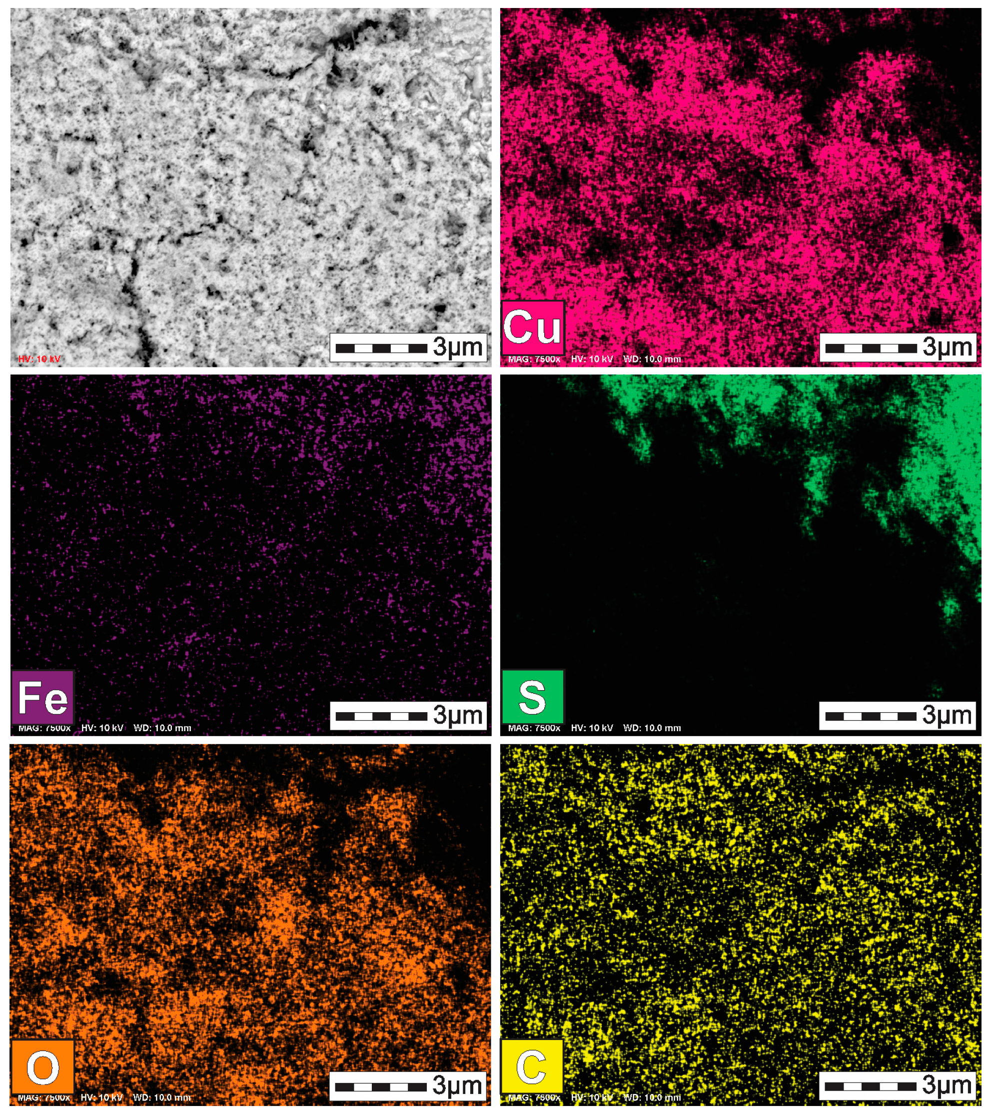
Figure 14 shows the micrograph and elemental mappings of sample M6 at 7500×. As can be seen, iron and sulfur elements were considerably decreased, consistent with results seen in Table 1, where the iron concentration in solution was the highest. This result reveals that chalcopyrite reduction is favored at this condition. It is also possible to observe the predominant presence of copper and oxygen elements, which can be related to the formation of copper oxides and metallic copper species. A small area containing sulfur and copper elements can be associated with the formation of copper sulfide species. This result is consistent with the X-ray characterization presented by Jasso-Recio et al. [30].
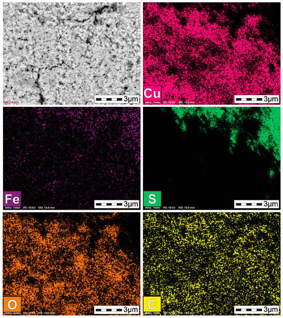
Figure 14.
Elemental mapping of M6 at 7500×.
It is important to note that all samples subjected to different cathodic polarization cycles, including M6, were rinsed with deionized water to remove the residual acetic acid from the surface of chalcopyrite; however, it is important to consider that acetate could probably be electro-adsorbed on the surface of chalcopyrite when it was cathodically polarized. Therefore, from a mechanistic viewpoint, it is possible to consider the occurrence of a similar mechanism reported by Martínez-Gómez et al. [31] for the formation of copper oxides; i.e., chalcopyrite can be electro-reduced under this condition to metallic copper. Once metallic copper is produced, the polarized chalcopyrite electrode is withdrawn from the reactor, and metallic copper is easily oxidized with oxygen from the air to produce copper oxides species. The presence of electro-adsorbed acetate can promote the formation of copper acetate. It is important to consider that acetate ion can be generated from the electro-reduction of the acetic acid molecules, according to Equation (6). As can be seen in Figure 14, carbon and oxygen elements are present and can be related to the formation of small amounts of copper acetate species.
According to results shown in previous figures, it is possible to propose the next reaction mechanism for the production of copper acetate: (a) metallic copper is produced during the cathodic polarization of chalcopyrite (Equation (9)), (b) metallic copper can react with oxygen, electro-adsorbed acetate, and monoatomic hydrogen when the polarized chalcopyrite electrode is withdrawn from the electrochemical cell, according to Equation (10).
Cu0 + 2H+ + 2CH3COO− + O2 → Cu(CH3COO)2 + 2OH−
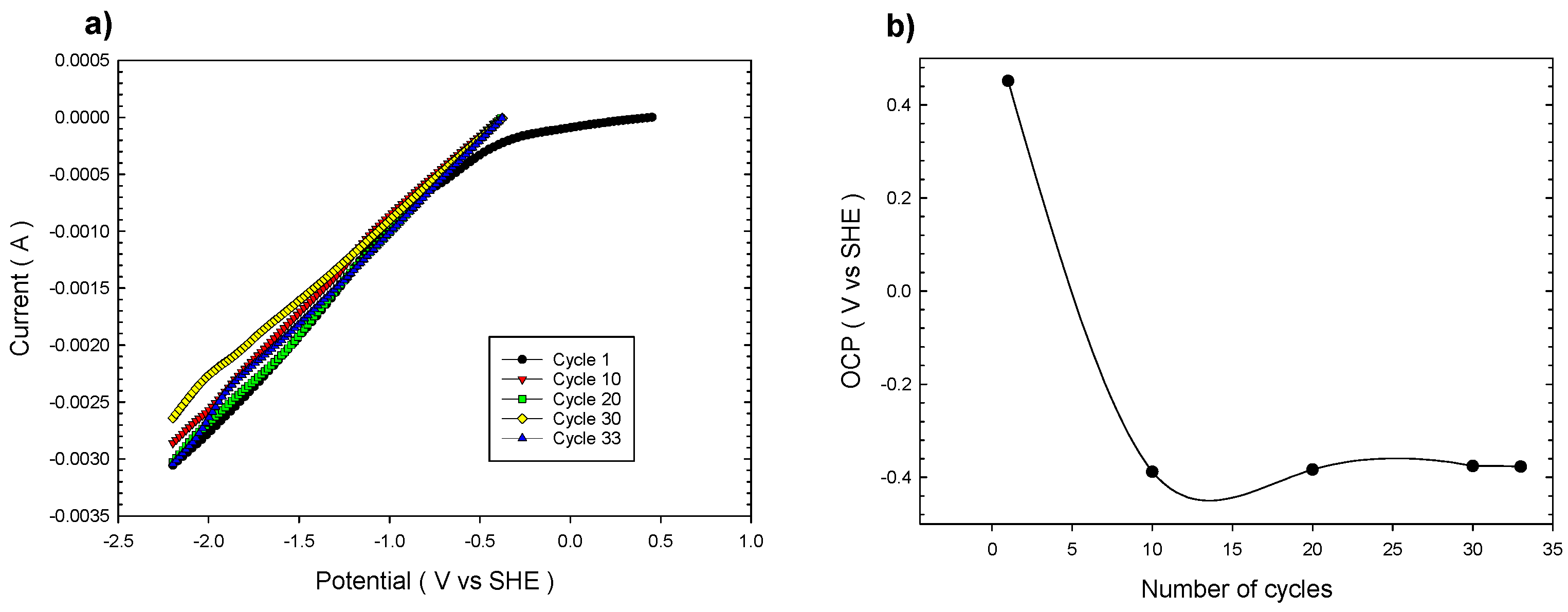
In order to confirm this possibility, it was decided to successively polarize the chalcopyrite electrode during 33 cycles (Figure 15). The solid product formed on the chalcopyrite surface was characterized by the X-ray diffraction technique.
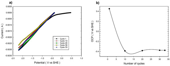
Figure 15.
(a) Multiple cathodic linear voltammetries for chalcopyrite from OCP up to −2.2 V vs. SHE in 3 M acetic acid at 20 mV/s and 25 °C without stirring. (b) OCP evolution with respect to the number of cathodic polarization cycles.
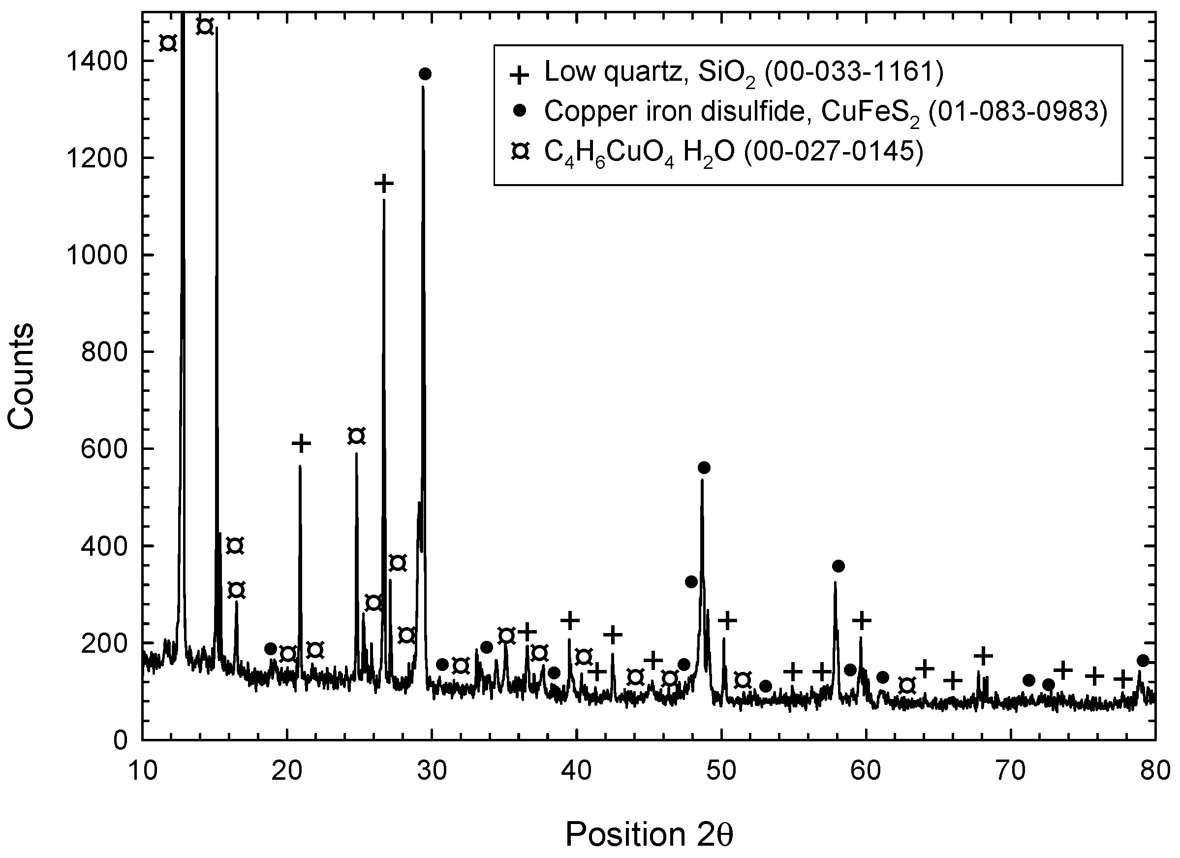
Figure 16 displays the X-ray diffraction pattern of the solid product obtained during the multiple cathodic polarization of chalcopyrite (33 cycles) in 3 M acetic acid. The main product corresponded to a copper acetate species (C4H6CuO4H2O). This result confirms that copper acetate type species can be produced when chalcopyrite electrode is continuously polarized during 33 cycles. It is also possible to validate that the formation of a passivating sulfur layer is inhibited in this novel system.

Figure 16.
X-ray diffraction pattern of chalcopyrite electrode polarized during 33 cycles from the OCP to −2.2 V vs. SHE at 0.02 V/s using 3 M acetic acid without stirring.
4. Conclusions
- Chalcopyrite can be transformed to less refractory copper phases (copper sulfide, copper oxides, metallic copper) using acetic acid as a leaching medium during electro-assisted reduction.
- When chalcopyrite is subjected to multiple cathodic polarization cycles in 3 M acetic acid, the conventional passivation phenomenon caused by the formation of sulfur layers does not occur; the current density is maintained during 11 polarization cycles.
- Chalcopyritic iron is continuously released when chalcopyrite polarization is increased from 1 to 11 cycles.
- OCP continuously decreased from 0.5 to −0.3 V vs. SHE at 1 and 11 polarization cycles, respectively, revealing the formation of less refractory copper phases.
- Characterization of solid products by FESEM-EDS techniques revealed that bornite is mainly formed at 1 cathodic polarization cycle, while copper sulfides and copper can be formed when the polarization is increased up to 7, 9, and 11 cycles.
- Metallic copper can be oxidized when it is withdrawn from the electrochemical cell producing copper oxides species.
- Cathodic polarization of chalcopyrite performed during 33 cycles from OCP to −2.2 V vs. SHE, showed the possibility of increasing the chalcopyrite transformation to less refractory phases, i.e., metallic copper. The latter can react with oxygen and electro-adsorbed acetate, producing copper acetate-type species (C4H6CuO4H2O).
Author Contributions
Conceptualization, L.D.J.-R., R.P.-G. and J.C.F.-A.; methodology, L.D.J.-R., A.V.E.-F., A.F.-V., J.T.-T., J.C.F.-A. and R.P.-G.; investigation, L.D.J.-R. and A.V.E.-F.; writing—original draft preparation, L.D.J.-R., J.C.F.-A., R.P.-G., A.F.-V., A.V.E.-F. and J.T.-T.; supervision, J.C.F.-A.; project administration, J.C.F.-A.; funding acquisition, J.C.F.-A., R.P.-G., A.F.-V. and J.T.-T. All authors have read and agreed to the published version of the manuscript.
Funding
The APC was funded by CINVESTAV.
Data Availability Statement
The original contributions presented in the study are included in the article, further inquiries can be directed to the corresponding author.
Acknowledgments
Laura Denisse Jasso Recio and Aldo Valentín Enríquez Farias are grateful to CONAHCyT (México) for the postgraduate scholarship received. Likewise, the collaboration of Martha Rivas (Microstructural characterization), Socorro García and Ana Muñiz (Chemical Analysis), Sergio Rodríguez and Félix Ortega (X-ray diffraction characterization) in this investigation is duly recognized.
Conflicts of Interest
The authors declare no conflicts of interest.
References
- Daehn, K.; Allanore, A. Electrolytic production of copper from chalcopyrite. Curr. Opin. Electrochem. 2020, 22, 110–119. [Google Scholar]
- Martínez-Gómez, V.J.; Fuentes-Aceituno, J.C.; Garibay, R.P.; Ordaz-Hernández, K.; Siller, D.M.P. Effect of galena during the electro-assisted reductive leaching of a chalcopyrite concentrate in HCl solutions. Miner. Eng. 2023, 203, 108355. [Google Scholar] [CrossRef]
- Burkin, A.R. Solid-State Transformations during Leaching. Min. Sci. Eng. 1969, 1, 4–14. [Google Scholar]
- Ammou-Chokroum, M.; Cambazoglu, M.; Steinmetz, D. Oxydation ménagée de la chalcopyrite en solution acide: Analyse cinétique des réactions. I. Modèles chimiques. Bull. Société Française Minéralogie Cristallogr. 1977, 100, 149–161. [Google Scholar]
- Munoz, P.B.; Miller, J.D.; Wadsworth, M.E. Reaction mechanism for the acid ferric sulfate leaching of chalcopyrite. Metall. Trans. B 1979, 10, 149–158. [Google Scholar] [CrossRef]
- Córdoba, E.M.; Muñoz, J.A.; Blázquez, M.L.; González, F.; Ballester, A. Leaching of chalcopyrite with ferric ion. Part I: General aspects. Hydrometallurgy 2008, 93, 81–87. [Google Scholar]
- Yang, Y.; Harmer-Bassell, S.; Chen, M. Synchrotron-based XPS and NEXAFS study of surface chemical species during electrochemical oxidation of chalcopyrite. Hydrometallurgy 2015, 156, 89–98. [Google Scholar]
- Castillo-Magallanes, N.; Cruz, R.; Lázaro, I. Effect of organic agentes on the oxidation process of chalcopyrite in a sulfuric acid solution. Electrochim. Acta 2020, 355, 136789. [Google Scholar]
- Crundwell, F.K.; Van Aswegen, A.; Bryson, L.J.; Biley, C.; Craig, D.; Marsicano, V.D.; Keartland, J.M. The effect of visible light on the dissolution of natural chalcopyrite (CuFeS2) in sulphuric acid solutions. Hydrometallurgy 2015, 158, 119–131. [Google Scholar]
- Khoshkhoo, M.; Dopson, M.; Shchukarev, A.; Sandström, Å. Chalcopyrite leaching and bioleaching: An X-ray photoelectron spectroscopic (XPS) investigation on the nature of hindered dissolution. Hydrometallurgy 2014, 149, 220–227. [Google Scholar]
- Yoo, K.; Kim, S.K.; Lee, J.C.; Ito, M.; Tsunekawa, M.; Hiroyoshi, N. Effect of chloride ions and leaching rate of chalcopyrite. Miner. Eng. 2010, 23, 471–477. [Google Scholar] [CrossRef]
- Allanore, A.; Lavelaine, H.; Birat, J.P.; Valentin, G.; Lapicque, F. Experimental investigation of cell design for the electrolysis of iron oxide suspensions in alkaline electrolyte. J. Appl. Electrochem. 2010, 40, 1957–1966. [Google Scholar] [CrossRef]
- Tian, Z.; Li, H.; Wei, Q.; Qin, W.; Yang, C. Effects of redox potential on chalcopyrite leaching: An overview. Miner. Eng. 2021, 172, 107135. [Google Scholar] [CrossRef]
- Nicol, M.; Miki, H.; Zhang, S. The anodic behaviour of chalcopyrite in chloride solutions: Voltammetry. Hydrometallurgy 2017, 171, 198–205. [Google Scholar] [CrossRef]
- O’Connor, G.M.; Eksteen, J.J. A critical review of the passivation and semiconductor mechanisms of chalcopyrite leaching. Miner. Eng. 2020, 154, 106401. [Google Scholar] [CrossRef]
- Liu, X.J.; Liao, Y.; Ma, H.; Liu, Q. Electrochemical characterizations and galvanic effect of chalcopyrite leaching and passivation-A review. Miner. Eng. 2024, 210, 108673. [Google Scholar] [CrossRef]
- Baba, A.A.; Ayinla, K.I.; Adekola, F.A.; Ghosh, M.K.; Ayanda, O.S.; Bale, R.B.; Sheik, A.R.; Pradhan, S.R. A Review on Novel Techniques for Chalcopyrite Ore Processing. Int. J. Min. Eng. Miner. Process. 2012, 1, 1–16. [Google Scholar]
- Prasad, S.; Pandey, B.D. Alternative processes for treatment of chalcopyrite—A review. Miner. Eng. 1998, 11, 763–781. [Google Scholar] [CrossRef]
- Liu, X.; Du, Z.; Sun, C.; Zhang, N. A review on the electrochemical analysis of sulfide minerals—Pyrite, chalcopyrite, and galena. Green Smart Min. Eng. 2025, 2, 18–31. [Google Scholar] [CrossRef]
- Allanore, A. Electrochemical Engineering for Commodity Metals Extraction. Electrochem. Soc. Interface 2017, 26, 63. [Google Scholar] [CrossRef]
- Dreisinger, D.; Abed, N. A fundamental study of the reductive leaching of chalcopyrite using metallic iron part I: Kinetic analysis. Hydrometallurgy 2002, 66, 37–57. [Google Scholar] [CrossRef]
- Biegler, T.; Swift, D.A. The Electrolytic Reduction of Chalcopyrite in Acid Solution. J. Appl. Electrochem. 1976, 6, 229–235. [Google Scholar]
- Blech, I.A.; Kruger, J. Further Evidence for Monoatomic Hydrogen as a Darkening Agent in Chemography. J. Electrochem. Soc. 1984, 131, 2455. [Google Scholar]
- Ye, J.; Zang, Y.; Wang, Q.; Zhang, Y.; Sun, D.; Zhang, L.; Wang, G.; Zheng, X.; Zhu, J. Nitrogen doped FeS2 nanoparticles for efficient and stable hydrogen evolution reaction. J. Energy Chem. 2021, 56, 283–289. [Google Scholar] [CrossRef]
- Li, Z.; Jalil, S.A.; Singh, S.C.; Li, W.; Wei, X.; Guo, C. Significantly enhanced electrocatalytic activity of copper for hydrogen evolution reaction through femtosecond laser blackening. Int. J. Hydrogen Energy 2021, 46, 10783–10788. [Google Scholar]
- Fujimura, T.; Kunimoto, M.; Fukunaka, Y.; Homma, T. Analysis of the hydrogen Evolution reaction at Ni micro-patterned electrodes. Electrochim. Acta 2021, 368, 137678. [Google Scholar]
- Marinović, V.; Despić, A.R. Cathodic Hydrogen Evolution from Aqueous Solutions of Acetic Acid. Russ. J. Electrochem. 2004, 40, 995–999. [Google Scholar] [CrossRef]
- Martínez-Gómez, V.J.; Fuentes-Aceituno, J.C.; Pérez-Garibay, R.; Lee, J.-C. A phenomenological study of the electro-assisted reductive leaching of chalcopyrite. Hydrometallurgy 2016, 164, 54–63. [Google Scholar]
- Biegler, T.; Constable, D.C. Continuous electrolytic reduction of a chalcopyrite slurry. J. Appl. Electrochem. 1977, 7, 175–179. [Google Scholar]
- Jasso-Recio, L.D.; Fuentes-Aceituno, J.C.; Pérez-Garibay, R. Electro-assisted reduction of chalcopyrite using acetic acid. The feasibility to use weak and less aggressive acids. Miner. Eng. 2024, 205, 108482. [Google Scholar]
- Martínez-Gómez, V.J.; Fuentes-Aceituno, J.C.; Pérez-Garibay, R.; Lee, J.-C. A study of the electro-assisted reductive leaching of a chalcopyrite concentrate in HCl solutions. Part I: Kinetic behavior and nature of the chalcopyrite reduction. Hydrometallurgy 2018, 181, 195–205. [Google Scholar] [CrossRef]


Disclaimer/Publisher’s Note: The statements, opinions and data contained in all publications are solely those of the individual author(s) and contributor(s) and not of MDPI and/or the editor(s). MDPI and/or the editor(s) disclaim responsibility for any injury to people or property resulting from any ideas, methods, instructions or products referred to in the content. |
© 2025 by the authors. Licensee MDPI, Basel, Switzerland. This article is an open access article distributed under the terms and conditions of the Creative Commons Attribution (CC BY) license (https://creativecommons.org/licenses/by/4.0/).