Article

Phosphorus Removal in Metallurgical-Grade Silicon via a Combined Approach of Si-Fe Solvent Refining and SiO2-TiO2-CaO-CaF2 Slag Refining

by
Yi Zhong
1,
Qing Zhao
2 and
Juncheng Li
3,*
1
School of Material Science and Engineering, Jiangsu University, Zhenjiang 212013, China
2
Key Laboratory for Ecological Metallurgy of Multimetallic Mineral (Ministry of Education), Northeastern University, Shenyang 110819, China
3
College of Energy and Environment Science, Yunnan Normal University, Kunming 650500, China
*
Author to whom correspondence should be addressed.
Metals 2025, 15(6), 668; https://doi.org/10.3390/met15060668
Submission received: 19 May 2025 / Revised: 11 June 2025 / Accepted: 14 June 2025 / Published: 16 June 2025

Abstract

:
As a critical impurity in the production of solar-grade silicon, the concentration of phosphorus (P) significantly affects photoelectric conversion efficiency. To address the challenge of P removal in solar-grade silicon production, this study proposes a combined process of Si-Fe solvent refining and SiO2-TiO2-CaO-CaF2 slag treatment. Under conditions utilizing collaborative refining with an alloy composition of Si-10 wt. %Fe and a slag composition of 32 wt. %SiO2-48 wt. %CaO-10 wt. %TiO2-10 wt. %CaF2, the removal rate of P in silicon can reach up to 96.8%. This paper investigates the effectiveness of combining solvent refining with slag making under fixed conditions of a Si-10 wt. %Fe alloy paired with various slag systems (no slag addition, binary slag SiO2-TiO2, ternary slag SiO2-CaO-TiO2, and quaternary slag SiO2-TiO2-CaO-CaF2). Based on the experimental results, the optimal TiO2 content in the slag system for maximizing P removal was analyzed and determined. Finally, leveraging both theoretical analysis and experimental findings, the mechanism of P removal was elucidated as a dual process: P is oxidized into Ca3(PO4)2 within the slag phase, and residual P is captured by the Fe-Si-Ti ternary phase.

1. Introduction

The rapid growth of the photovoltaic industry has escalated the demand for solar-grade silicon (SoG-Si), which requires ultra-high purity (≤0.1 ppm phosphorus (P), ≤0.1 ppm boron (B)) to minimize carrier recombination and maximize solar cell efficiency [1,2]. While the Siemens process dominates industrial production, its high energy consumption (>120 kWh/kg Si) and cost (>USD 20/kg Si) have spurred interest in metallurgical purification routes, offering potential cost reductions of 30–50% [3]. The purification of metallurgical silicon to solar-grade silicon via metallurgical methods encompasses various process routes, including directional solidification [4,5], acid leaching [6,7], blowing techniques [8], solvent refining [9,10,11], and slag refining [12,13,14]. While these methods are effective in removing metallic impurities (e.g., Fe, Al), they struggle to remove critical nonmetallic impurities, such as P and B, due to their high coefficients of segregation (kP = 0.35, kB = 0.8) and low vapor pressures.
Among these techniques, solvent refining primarily utilizes the segregation effect of impurities to remove them from silicon. This is achieved by leveraging the differences in the solubility of impurities between the silicon matrix and alloy phases. Iron (Fe) is widely adopted as a solvent due to its low solubility in Si (0.5 at% at 1300 °C), cost-effectiveness, and strong affinity for P [15,16,17]. More studies will also use aluminum (Al) [18,19], calcium (Ca) [20,21], and copper (Cu) [22,23]. However, standalone Si-Fe refining achieves limited P removal (≤57.4%) due to insufficient partitioning of P into FeSi2 phases [24,25,26,27,28]. Recent advancements have focused on ternary alloy systems (e.g., Si-Fe-Ti) and hybrid processes combining alloying with slag refining. Deng et al. [29] demonstrated that introducing Ti into Si-Fe alloys forms Fe-Si-Ti ternary phases, enhancing P removal to 71.2% through P entrapment in Ti-rich intermetallics [30,31]. Similarly, slag refining employs reactive oxide systems (e.g., CaO-SiO2-Al2O3) to oxidize P into stable phosphates (e.g., Ca3(PO4)2) via redox reactions at the slag–silicon interface. Hosseinpour et al. [32] achieved 86% P removal by coupling Si-20%Fe solvent refining with Al2O3-CaO-SiO2-MgO slag; however, this efficiency remains insufficient to meet SoG-Si standards. A critical bottleneck stems from the single-mechanism limitation of existing methods: solvent refining primarily traps P in intermetallic phases, while slag refining relies on oxidation. Neither approach fully exploits synergistic effects between alloy-mediated segregation and slag-driven oxidation. Based on the characteristic that Si-Fe-Ti ternary systems exhibit a strong affinity for P, which facilitates its removal [33], and considering the findings by Gu et al. [34], who successfully synthesized Si-Ti alloys via TiO2-containing slag, this study proposes a synergistic refining method utilizing TiO2-containing slag and Si-Fe alloy. The aim is to remove phosphorus through a dual-mechanism approach, thereby enhancing the overall efficiency of P removal.
To summarize, in order to further enhance the removal efficiency of P impurities in silicon via Si-Fe solvent refining, this study proposes a dual-mechanism purification strategy that integrates Si-Fe solvent refining with SiO2-TiO2-CaO-CaF2 slag treatment. First, thermodynamic calculations via FactSage 8.1 were employed to predict phase equilibria and P partitioning behaviors, guiding the design of slag compositions and refining parameters. And, the roles of TiO2 and CaF2 were systematically elucidated. Furthermore, the mechanism of enhanced P removal via the synergistic effects between alloy-mediated segregation and slag-driven oxidation was also discussed. This work advances metallurgical silicon purification by demonstrating a scalable, energy-efficient route to SoG-Si, with implications for reducing photovoltaic manufacturing costs and carbon footprints.

2. Materials and Methods

2.1. Materials and Reagents

This study is dedicated to enhancing the impurity removal efficiency in the Si-Fe alloy system. The experimental investigation focuses on the removal of P using various slag agents under an alloy composition of Si-10 wt. %Fe, aiming to achieve a high P removal rate while maintaining a relatively high yield of primary silicon. Furthermore, to facilitate a more detailed analysis of P distribution, this study amplifies the P content in silicon by introducing P into the pre-prepared Si-P master alloy phase silicon. Consequently, the initial composition of the alloy is set as Si-10 wt. %Fe-1 wt. %P. The compositions of the slag-making agents for each experimental group are summarized in Table 1. Among the groups, S1 underwent refining using only the alloy without adding any slag; this group was compared with the experimental groups where slag was added to demonstrate the effectiveness of the selected slag system in removing P from silicon.
For the solvent refining experiments, the raw materials utilized were SoG-Si with a purity of 6N (99.9999%), iron (Fe) with a purity of 3N (99.9%), and a pre-synthesized Si-P master alloy. The slag used in the slag refining process consisted of silicon dioxide (SiO2, analytical reagent grade, AR), titanium dioxide (TiO2, AR), calcium oxide (CaO, AR), and calcium fluoride (CaF2, AR). The reagents used in this study were provided by Sinopharm Chemical Reagent Co., Ltd. (Shanghai, China).

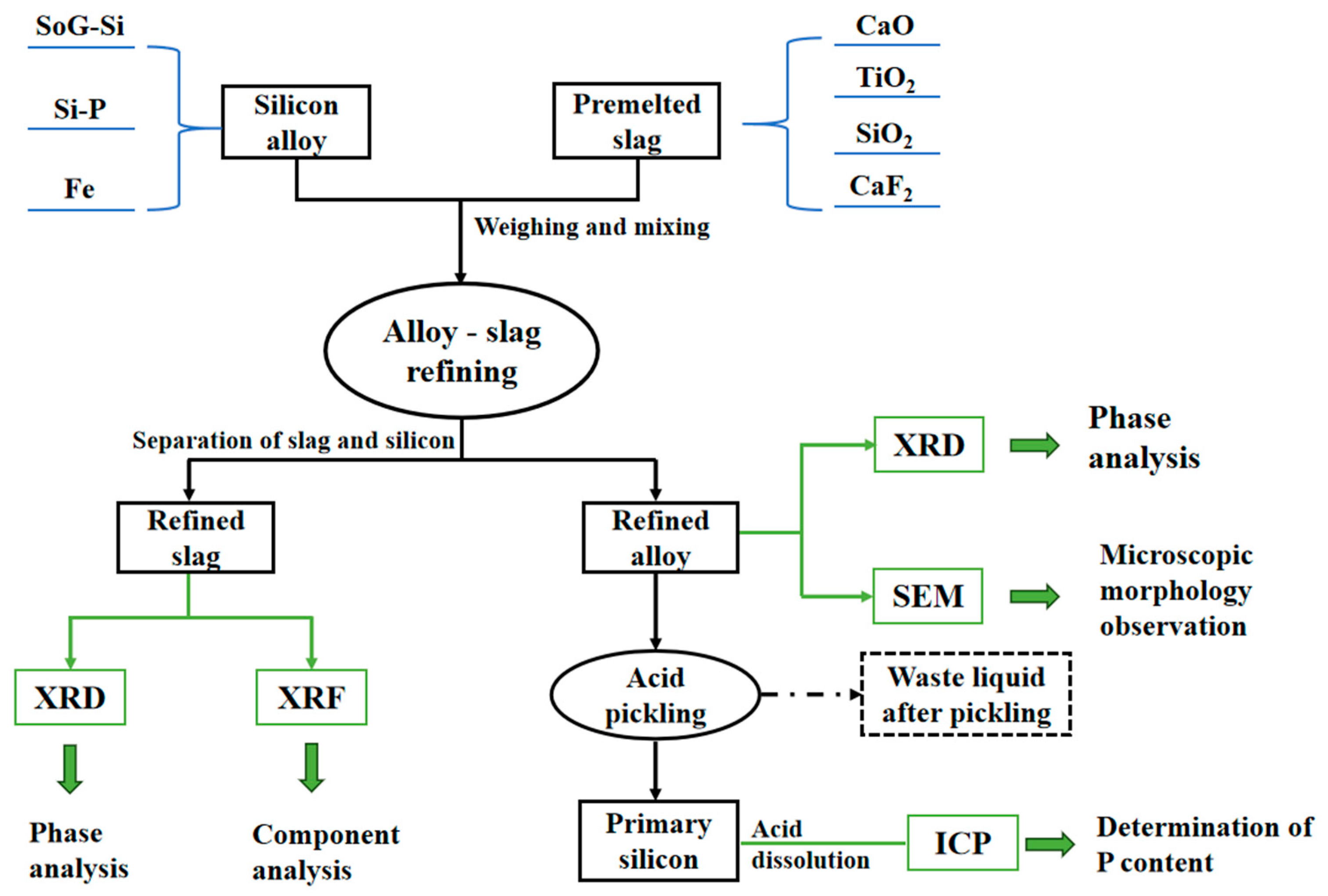
2.2. Experimental Procedure

To ensure compositional uniformity of the slag components, the slags listed in Table 1 were pre-melted at 1650 °C for 1 h before the experiment. As illustrated in Table 1, various compositions of slag-making agents were incorporated into the Si-10 wt. %Fe alloy. Subsequently, the experimental raw materials for each group were transferred into a high-purity graphite crucible. The crucible was sealed with a graphite lid and nested within a larger graphite crucible before being placed in a tube furnace. Under an argon atmosphere, the sample was heated to a temperature range of 1550–1650 °C, maintained at this temperature for 1 h, and subsequently cooled at a rate of 5 °C/min. The obtained experimental samples were divided into three portions for different analytical purposes. One was designated for microscopic characterization. Scanning Electron Microscopy (SEM; FEI Quanta250, Hillsboro, OR, USA) in conjunction with Energy-Dispersive X-ray Spectroscopy (EDS; FEI Quanta250, Hillsboro, OR, USA) was utilized to systematically examine and analyze the microstructure as well as the distribution of impurities within the samples. One was meticulously ground into a fine powder, which was subsequently subjected to X-ray Diffraction (XRD; T’TRⅢ, Tokyo, Japan) and X-ray Fluorescence Spectroscopy (XRF; ARL Advant’X IntelliPower-4200, Massachusetts, MA, USA) analyses for the determination of phase compositions. The other was used for pickling.
The pickling procedure was described as follows. The refined alloy obtained from the experiment was ground into fine powder (particle size < 20 μm). Subsequently, the powder was subjected to leaching with aqua regia (HCl:HNO3 = 3:1 by volume) at an elevated temperature for 2 h. Following the leaching process, the powdered silicon was thoroughly washed with deionized water until the solution reached neutrality. It was then dried in a vacuum drying oven. Finally, the powders were dissolved in hydrofluoric acid (HF), and the impurity concentration was analyzed using ICP-AES (ICP-AES; VISTA-MPX, Santa Clara, CA, USA).
The overall experimental workflow is illustrated in Figure 1.

3. Results and Discussion

3.1. Thermodynamic Analysis of P Removal in Alloy-Slagging Refining

Before experimental validation, the thermodynamic software FactSage 8.1 was conducted to evaluate the feasibility of P removal in the Si-Fe alloy/SiO2-TiO2-CaO(-CaF2) slag system. Specifically, the Reaction and Equilib modules were employed to calculate the thermodynamic properties of chemical reactions and predict species distribution and concentrations at equilibrium. The changes in the composition of the thermodynamic equilibrium phase and liquid phase during the smelting process were simulated, thereby preliminarily confirming the feasibility of the proposed approach.
Figure 2 illustrates the simulation results for the equilibrium phase of the slag system composed of 36 wt. %SiO2-54 wt. %CaO-10 wt. %TiO2, coupled with the alloy containing Si-10 wt. %Fe-1 wt. %P. As depicted in the figure, the precipitation sequence of phases within the alloy follows the order of primary silicon, TiSi2, FeSi2, and P compounds. The initial precipitation temperature of silicon was approximately 1375 °C. Subsequently, at around 1250 °C, the TiSi2 phase begins to precipitate, coinciding with a deceleration in the precipitation rate of primary silicon. At approximately 1150 °C, the precipitation of FeSi2 occurred, leading to a temporary decrease in the amount of primary silicon before it rebounded and stabilized. Finally, as the temperature decreased below 1000 °C, the impurity phase containing P started to precipitate, predominantly in the form of FeP compounds. Following this stage, the liquid phase of the alloy completely disappeared, and the precipitation amounts of all phases stabilized. Notably, TiO2 in the slag was nearly entirely reduced and incorporated into the alloy as TiSi2, leaving residual slag composed of CaSiO3 and Ca3Si2O7 phases. These results confirmed the selective migration of Ti into the alloy, a critical factor for P entrapment.
Figure 3 shows the simulation results for the equilibrium phase during the refining of the Si-Fe alloy in conjunction with the SiO2-TiO2-CaO-CaF2 quaternary slag system. As illustrated in Figure 3, primary crystalline silicon precipitates initially, followed by TiSi2 and FeSi2 phases, with the P-containing compound precipitating last. When compared to the equilibrium phase simulation without CaF2 addition, while the phase precipitation sequence (primary Si → TiSi2 → FeSi2 → FeP) remained consistent, the addition of CaF2 reduced the liquidus temperature of the slag by approximately 100 °C, promoting the formation of Ca4Si2F2O7. This is a well-established phenomenon supported by extensive previous studies. The corresponding results show that the F⁻ ions liberated from CaF2 disrupt the silicate network structure of slag, significantly lowering viscosity, and then the reduced viscosity accelerates mass transfer at the slag–metal interface, thereby improving kinetic conditions for impurity removal [35,36]. The precipitation temperature of FeSi2 dropped below 1000 °C, widening the temperature gap between TiSi2 and FeSi2 formation. Importantly, the addition of CaF2 did not modify the phase composition of the alloy but significantly enhanced the kinetics of the slag system, thereby promoting efficient mass transfer between the alloy and the slag. It is important to highlight that the content of the P-rich phase in TiSi2 plays a critical role in determining the efficiency of phosphorus removal. However, an increase in TiSi2 content leads to substantial consumption of Si, thereby reducing the amount of primary silicon precipitation. The quantity of primary silicon precipitation is directly correlated with the yield of the target product.
Figure 4 shows the relationships between the TiSi2 precipitation amount in the P-rich phase and the yield of initial crystalline silicon as a functions of TiO2 content. As illustrated in Figure 4, increasing the TiO2 dosage linearly elevated the TiSi2 content in the alloy (R2 = 0.98), driven by enhanced Ti migration from the slag. However, with the increasing addition of TiO2, the formation of TiSi2 consumes a significant amount of silicon, leading to a downward trend in both the theoretical precipitation amount and yield of primary crystalline silicon, decreasing from 82% to 64%. While the introduction of TiO2 during the refining process promotes the formation of the P-rich phase, it simultaneously limits the recovery of silicon. The optimization of TiO2 content at 10 wt. % was determined through a systematic evaluation of two competing factors: (1) Regarding phosphorus removal efficiency, thermodynamic simulations and the experimental results consistently demonstrate that increasing TiO2 content enhances TiSi2 phase formation, which effectively concentrates phosphorus impurity; (2) Regarding silicon yield preservation, however, excessive TiO2 (>10 wt. %) triggers significant silicon consumption through Ti-Si alloy formation, reducing primary silicon yield.

3.2. Microstructural Morphological Analysis

3.2.1. The Effect of Slag Component Variation on Phosphorus Removal Efficiency

To systematically evaluate the impact of slag composition on P removal efficiency, Figure 5 and Table 2 present the SEM-EDS results obtained from the samples derived from the aforementioned experimental groups.
For the slag-free condition (S1), the refined alloy comprised primarily FeSi2 and primary silicon phases. The microstructure of the Si-10 wt. %Fe alloy after high-temperature treatment is presented in Figure 5a. In the figure, the grayish-white region corresponded to the ferrosilicon alloy phase, while the dark gray area represented the silicon substrate. Iron, as the predominant impurity in metallurgical silicon, exhibited a strong affinity for P, readily forming iron–P compounds [37]. However, the SEM-EDS results from the Si-Fe alloy samples indicated no significant P enrichment in most Si-Fe phases. Existing studies [27] indicate that although iron serves as an effective getter for impurities, P cannot be efficiently separated from silicon via the Si-Fe alloy system, highlighting certain limitations in P removal using this refining method.
As for S2, the SEM-EDS analysis results of the alloy samples refined with binary slag SiO2-TiO2 are presented in Figure 5b and Table 2. The introduction of binary slag SiO2-TiO2 facilitated partial Ti migration into the alloy, as evidenced by trace Ti signals in EDS spectra However, the quantity of Ti incorporated into the alloy remained relatively low, and the primary constituents of the impurity segregation phase continued to be Fe and Si.
With the introduction of CaO to binary slag SiO2-TiO2 (S3), the Si-Fe alloy and the ternary slag agent effectively facilitated the separation of the refined slag and silicon. The SEM-EDS results for the refined alloy samples are illustrated in Figure 5c and summarized in Table 2. As clearly evident from the figure, the alloy comprised two impurity phases: one being the Si-Fe-Ti phase and the other being the Si-Fe phase. Under the experimental conditions, Si acted as a reducing agent to reduce TiO2 in the slag, causing Ti in the slag to migrate to the alloy, and then the above-mentioned Ti phase formed [33]. Based on the EDS compositional analysis, P predominantly accumulates within the Si-Fe-Ti ternary segregation phase. The incorporation of CaO into the ternary slag SiO2-TiO2-CaO (S3) significantly enhanced both impurity oxidation and alloy-mediated entrapment. The increased slag alkalinity promoted redox reactions at the slag–silicon interface, enabling partial P oxidation to Ca3(PO4)2 (detected via XRD in slag residues). Concurrently, the reduction in Ti from TiO2 facilitated the formation of Fe-Si-Ti ternary phases in the alloy, which exhibited strong P affinity (2.17 wt. % P in Fe-Si-Ti vs. 1.41 wt. % in FeSi2). This dual mechanism elevated the P removal efficiency to 93.4%, representing a substantial improvement over binary slag refining processes.
In an effort to further enhance the removal of P impurities based on existing research and optimize the experimental results, a slag system incorporating added flux CaF2 was selected. Figure 5d and Table 2 present the SEM and EDS test results of alloy samples refined from the Si-Fe alloy and SiO2-TiO2-CaO-CaF2 slag. The bright regions in the figure corresponded to impurity segregation phases. It is evident that three distinct impurity phases have precipitated, namely, points 4, 5, and 6 (The impurity phase regions where points 4, 5 and 6 were located were marked in Figure 5d). According to the corresponding EDS analysis, point 4 represented the TiSi2 phase, while points 5 and 6 corresponded to the Si-Fe-Ti ternary phase. Their chemical compositions were speculated to be Si64.3Fe28.3Ti7.4 and FeSi2Ti, respectively. The dark region denoted the silicon substrate. CaF2 enhanced interfacial reaction kinetics and promoted Ti migration into the alloy and the migration of P into the slag. SEM-EDS analysis revealed three distinct impurity phases: TiSi2, a Fe-Si-Ti ternary phase, and residual FeSi2. Map scanning (Figure 6) confirmed P enrichment in Ti-rich regions, with P content reaching 3.03 wt. % in Fe-Si-Ti phases. CaF2 also stabilized the formation of Ca4Si2F2O7 in the slag, which acted as a secondary P reservoir by incorporating oxidized P species. A similar study conducted by Shahbazian et al. [38,39] indicated that while CaF2 does not directly react with P, its addition reduces the viscosity of the slag, improves its fluidity, and significantly lowers the melting point, thereby enhancing the efficiency of P removal.

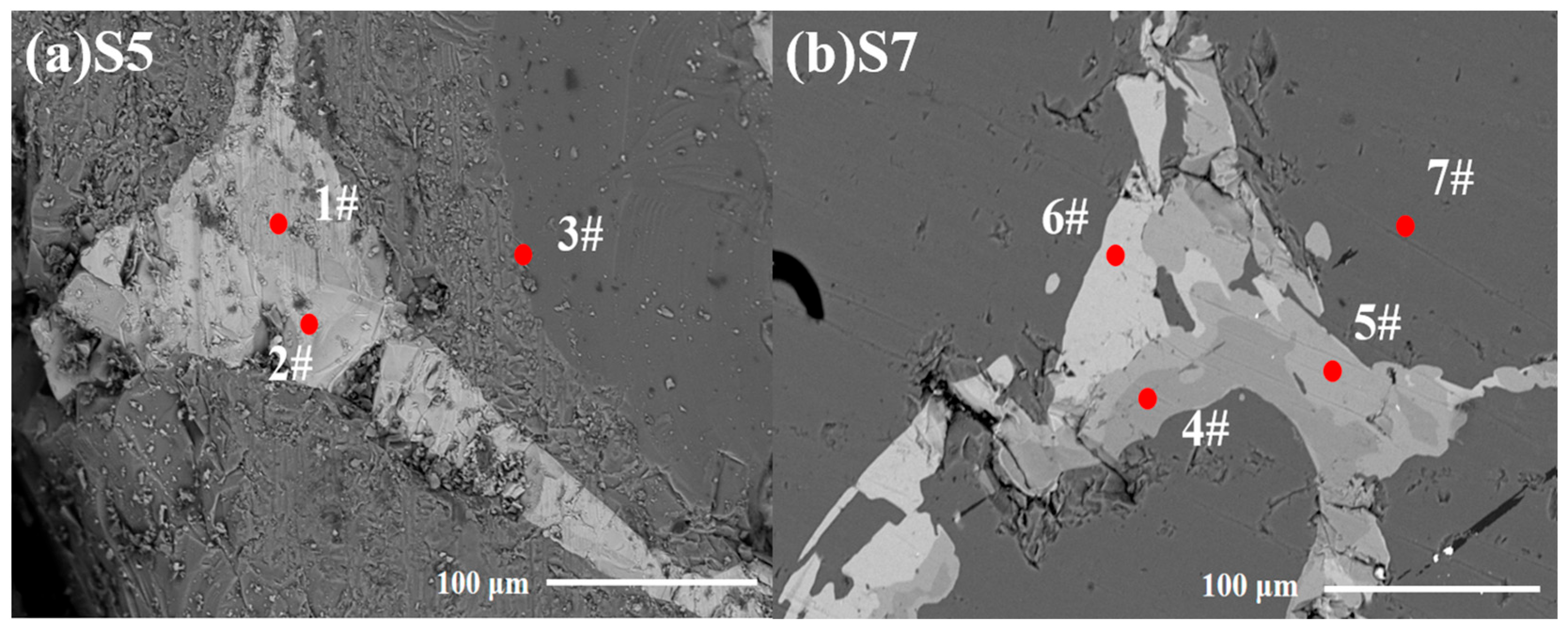
3.2.2. The Effect of TiO2 Content Variation on Phosphorus Removal Efficiency

The impact of varying TiO2 content in the slag from 5 to 20 wt. % on P removal efficiency was investigated under conditions of a CaO/SiO2 mass ratio of 1.5 and an initial CaF2 content of 10 wt. %. As shown in Figure 7 and Table 3, for 5 wt. % TiO2 (Figure 7a), the impurity phases primarily consisted of Fe-Si binary phases (FeSi2) and Fe-Si-Ti ternary phases (FeSi2Ti). EDS analysis (Table 3, points 1 & 3) showed P concentrations of 2.25 wt. % in FeSi2Ti and 1.00 wt. % in FeSi2, indicating limited P entrapment driven by TiO2 at this concentration. When TiO2 content increased to 20 wt. % (Figure 7b), the impurity phase complexity escalated, dominated by Ti-Si binary phases (TiSi2) and Fe-Ti-Si ternary phases (e.g., Si64.3Fe7.4Ti28.3). These phases exhibited enhanced P enrichment, with FeSi2Ti phases containing 3.03 wt. % P (Table 3, point 6). This finding underscores the critical role of TiO2 in promoting the formation of P-rich phases.

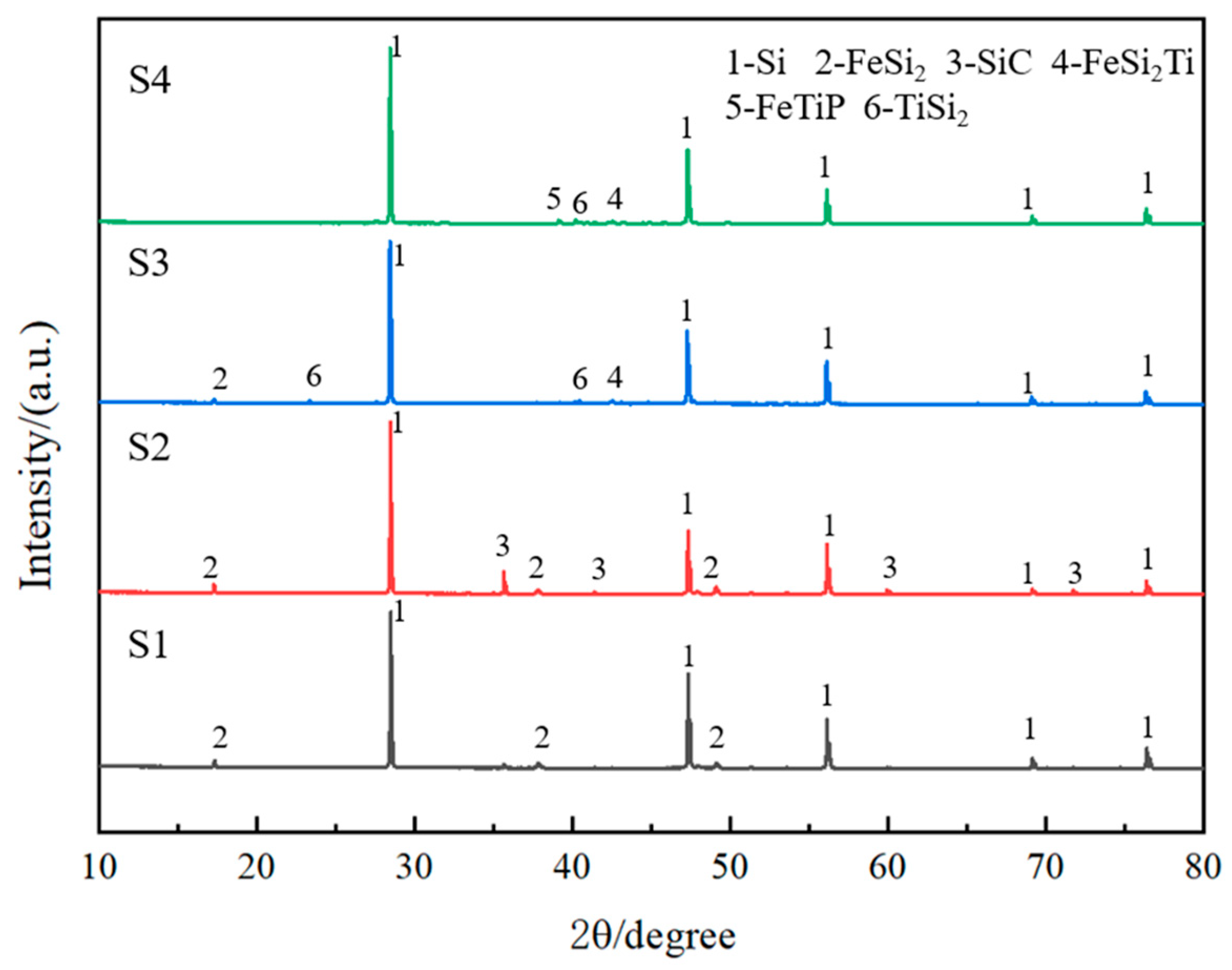
3.3. Compositional Analysis

To further investigate the phase compositions in the refined alloy and slag phases, XRD and XRF analyses were performed. Figure 8 and Figure 9, respectively, present the XRD results for the alloys and slag samples from each group. As shown in Figure 8, for samples S1 and S2, the major phases in the refined alloy were the primary silicon phase and the FeSi2 phase. In samples S3 and S4, a minor presence of P-containing compounds, as well as FeSi2Ti and TiSi2 phases, was observed. Both FeSi2Ti and TiSi2 phases demonstrated excellent P enrichment capabilities. Similar results discovered by Sakiani et al. [33] also indicated the generation of a small amount of the FeSi2Ti phase during the refining process of Si-Fe-Ti ternary alloys and confirmed that the Fe-Si-Ti phase was P rich phase, and the enrichment of P in the Si-Fe-Ti phase was not affected by the composition of this phase.
Figure 9 presents the XRD patterns of the slag phases corresponding to samples S2 through S4. As illustrated in Figure 9, the slag phase of sample S2 predominantly comprised SiO2, with TiO2 being nearly undetectable. This observation indicated that TiO2 was almost entirely consumed during the reaction process. Additionally, no newly formed elements were detected in the slag, suggesting that TiO2 was likely reduced by Si from the alloy and subsequently incorporated into the alloy phase. In the XRD analysis of samples S3 and S4, a minor amount of a containing compound, Ca3(PO4)2, was identified in the slag phases. This finding implied that upon the introduction of CaO-based slag, a portion of P underwent oxidation and was subsequently removed into the slag phase. When the concentration of SiO2 in the slag reached the critical value, P was mainly removed in the form of phosphate. In contrast, in a slag with a certain alkalinity, when P was removed in the form of PO43−, a higher LP (distribution ratio of P) can be obtained than when it was removed in the form of P3− [40]. In sample S4, the newly added CaF2 reacted with CaO and SiO2, primarily forming Ca4Si2O7F2. These experimental results aligned well with the equilibrium phase calculation outcomes in Figure 2 and Figure 3.
The XRF analysis results of the refining slags are presented in Table 4. As shown in the table, a significant amount of P migrated into the slag during the slag-making refining process. Furthermore, with variations in slag composition, the P content in the slag exhibited an increasing trend. Additionally, the residual Ti content in the slag remained relatively low, not exceeding 0.84 wt. %, which suggested that the majority of Ti elements had entered the alloy via reactions during the refining process. The XRF detection results of the slag phase also confirmed that after slag refining, the Ti element in the slag was almost entirely concentrated in the alloy phase, while a portion of the P in the alloy phase migrated into the slag phase. Moreover, the XRF results in Table 4 indicated that following the introduction of CaF2 as a slag agent, the P content in the slag was relatively elevated.

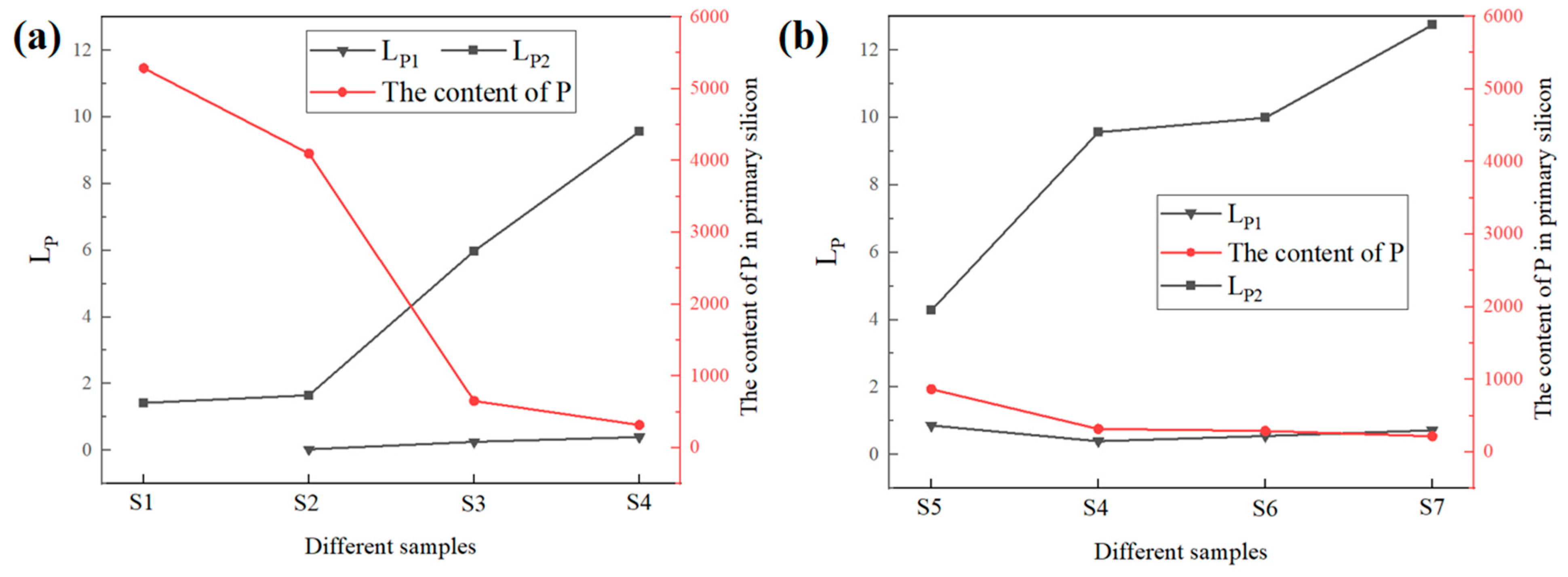
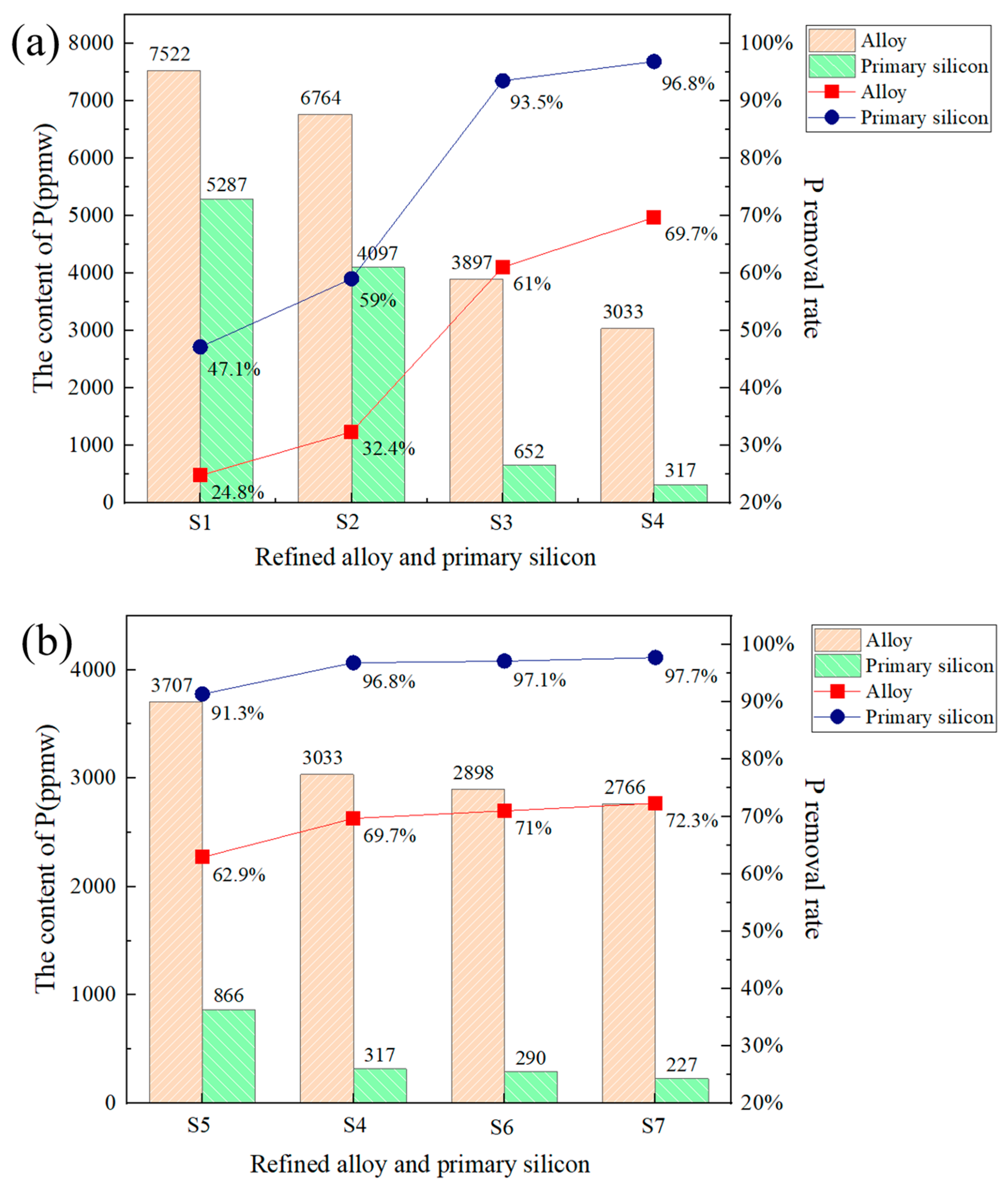
3.4. Phosphorus Removal Efficiency

The removal effect of P by alloy-slagging refining and acid washing can be described by the distribution ratio of P. Generally, a higher LP typically indicates a more effective removal rate [41]. Among them, the influence of slag refining on the distribution of P in silicon was characterized by the distribution ratio of P between the slag and alloy, denoted as LP1 as follows:
L P 1 = F i n a l   P   c o n t e n t s   i n   s l a g F i n a l   P   c o n t e n t s   i n   a l l o y
The influence of solvent refining on the distribution of P in silicon was expressed by the distribution ratio of P in alloy/silicon LP2 as follows:
L P 2 = F i n a l   P   c o n t e n t s   i n   a l l o y F i n a l   P   c o n t e n t s   i n   S i
The remaining P content in the alloy and slag of the corresponding experimental samples before and after pickling was determined (the P content in the alloy and slag was obtained by ICP and XRF detection, respectively), and the corresponding P distribution ratio for each group was calculated. The specific results obtained are shown in Figure 10. Figure 10a shows the variation of the P distribution ratio under different compositions of slag-making agents. It can be seen from the figure that with the change in the composition of the slag-making agents, both LP1 and LP2 showed an increasing trend. As shown in Figure 10a, both LP1 and LP2 increase significantly with slag complexity. The quaternary slag (S4) achieved the highest ratios (LP1 = 8.7, LP2 = 12.3), surpassing ternary (LP1 = 5.2, LP2 = 9.1) and binary (LP1 = 1.8, LP2 = 3.4) systems. This trend highlighted the synergy between slag oxidation and alloy entrapment, and Figure 10b further demonstrates the relationship between the P distribution ratio and the TiO2 content in the slag.
The P removal efficiency after alloy–slag refining is illustrated in Figure 11. A comparison analysis of the experimental results from samples S1 to S4 indicated that the refining effect of the Si-Fe alloy alone was relatively limited, achieving a P removal rate of merely 47.13%. The incorporation of slag markedly enhanced P removal efficiency. Standalone Si-Fe solvent refining (S1) achieved 47.13% efficiency, whereas ternary (S3) and quaternary (S4) slag systems elevated the efficiency to 93.4% and 96.85%, respectively. The TiO2 content in the slag is adjusted based on the quaternary slag system, and its effect on P removal is illustrated in Figure 11b. When the TiO2 concentration ranges between 5 wt. % and 20 wt. %, increasing the TiO2 dosage enhances P removal and improves the removal efficiency. However, when the TiO2 content exceeded 10 wt. %, the increase in P removal efficiency became relatively gradual. Furthermore, as illustrated in Figure 11b, the P removal rate of the S5 sample is lower compared to that of the S3 group and the S4 group. The observed variation in P removal efficiency among the samples can be systematically explained through their compositional differences. While S3 represents a ternary slag system (SiO2-CaO-TiO2), both S4 and S5 are quaternary systems (SiO2-TiO2-CaO-CaF2) with distinct CaF2 concentrations (10% and 5%, respectively). The superior performance of S4 stems from two synergistic effects—the presence of CaF2 significantly enhances slag fluidity to promote interfacial reactions, while its higher TiO2 content (10% vs. 5%) facilitates the greater formation of the crucial Si-Fe-Ti phosphorus-rich phase. This dual mechanism explains why S4 achieves optimal phosphorus removal, whereas S5′s reduced TiO2 con-tent limits phosphorous phase formation despite sharing the quaternary composition framework.

3.5. Dephosphorization Mechanism Analysis

Based on the existing experimental results, this study speculated on the potential reactions that could occur during the alloy–slag refining process and calculated their corresponding standard Gibbs free reaction energies. The potential reactions occurring during the refining process are presented in Table 5. Under the given experimental conditions, the standard Gibbs free energy of reaction (1) was relatively lower, indicating that this reaction was more likely to occur.
Based on the aforementioned experimental results and Gibbs free energy calculations, the dephosphorization mechanism proposed in this study was schematically depicted in Figure 12. The removal of P in this work mainly encompassed two pathways.
(1)
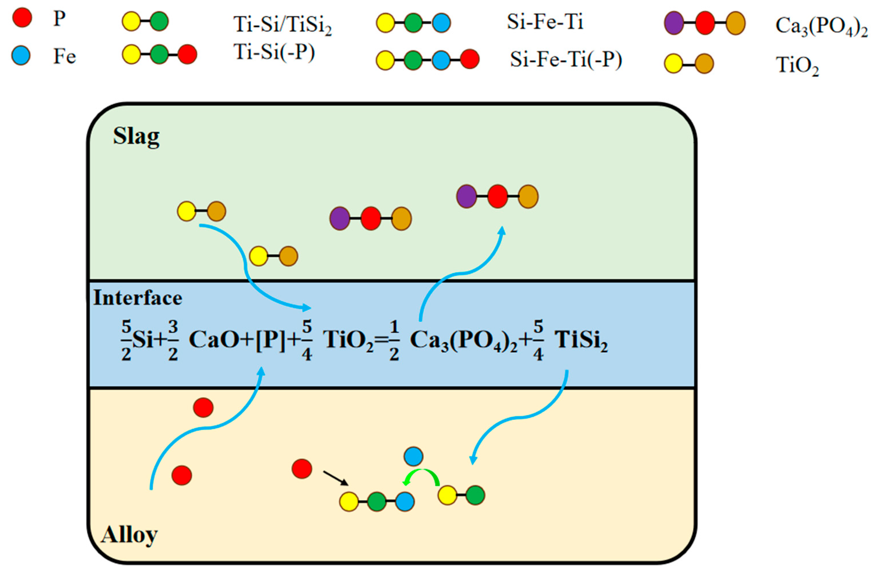
Oxidation of slagging agent: A portion of P in molten silicon migrated to the silicon–slag interface, where it was oxidized by the highly oxidizing slagging agent. This oxidation primarily resulted in the formation of P-containing compounds, predominantly calcium phosphate (Ca3(PO4)2). During this process, SiO2 functioned as an acidic matrix and supplied an abundant oxygen source, thereby facilitating the oxidation of P impurities into the slag phase. CaO created a strongly alkaline environment, enabling the effective formation of stable calcium phosphate compounds that subsequently entered the slag phase. The partial reduction in TiO2 produces Ti, which reacted with Fe and Si in the alloy to form the Si-Fe-Ti ternary phase and the TiSi2 phase, effectively capturing P impurities. Additionally, CaF2 lowered the melting point and enhanced the fluidity of the slag agent, thereby intensifying the reaction at the slag–silicon interface.
(2)
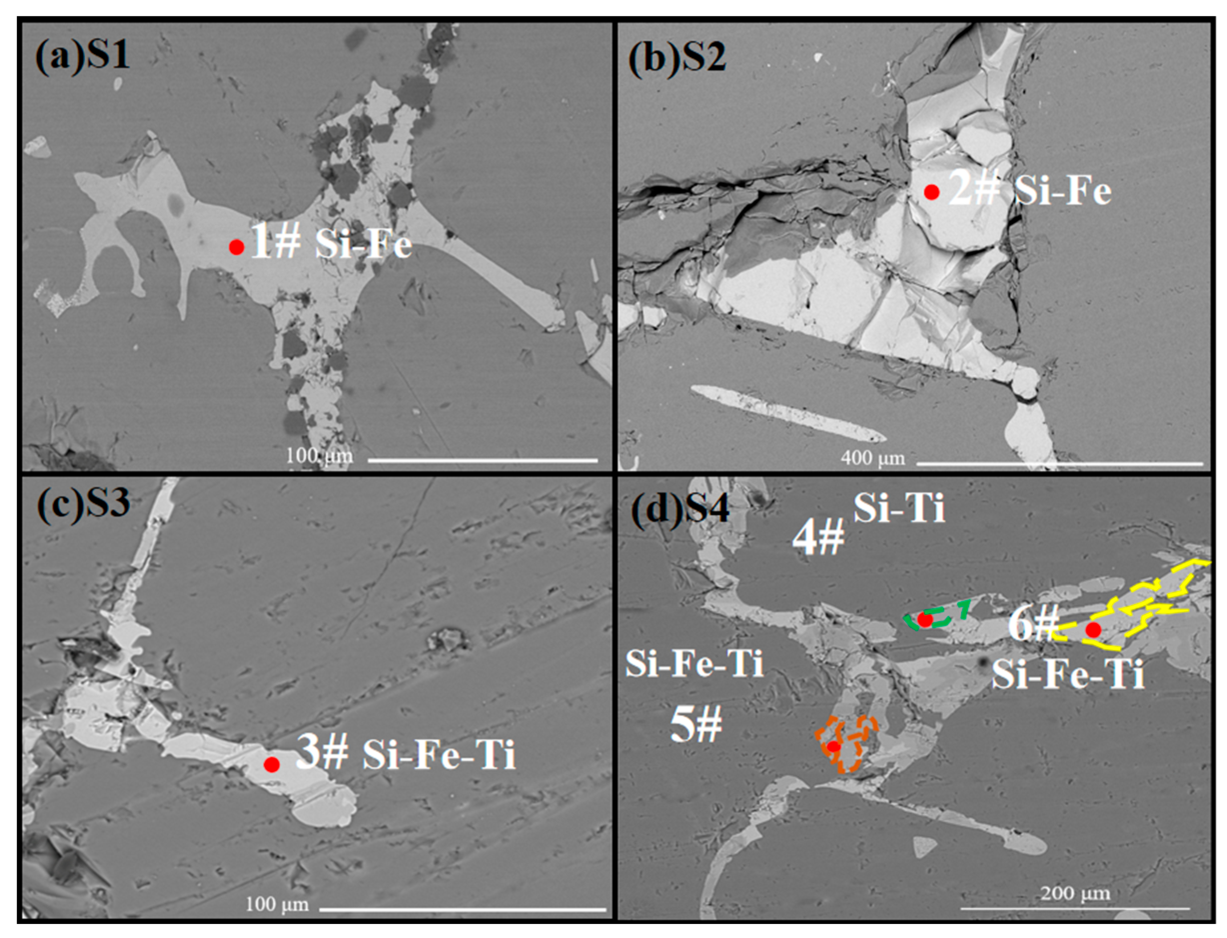
P-rich phase formation: Simultaneously, at elevated temperatures, P diffused toward the slag phase while TiO2 in the slag underwent chemical reduction. The equilibrium phase calculations and experimental findings collectively indicated that nearly all the Ti in the slag was reduced and migrated into the silicon matrix. This process resulted in phase reconfiguration within the alloy and the formation of a Si-Fe-Ti ternary phase. Excess Ti further reacted with silicon to form the TiSi2 phase. Both the Si-Fe-Ti ternary phase and the TiSi2 phase exhibited a strong affinity for P. According to SEM-EDS analysis, the majority of P in the refined alloy phases was concentrated in these two aforementioned phases. When the TiO2 content in the slag increased, the proportion of P-rich phases in the alloy also increased correspondingly, thereby enhancing the efficiency of P removal. This demonstrated that most of the P in the alloy phases was enriched in the Si-Fe-Ti and TiSi2 phases, which can subsequently be separated from the silicon matrix through acid pickling.

4. Conclusions

In this study, a Si-Fe alloy and SiO2-TiO2-CaO-CaF2 slag were employed for combined refining and P removal. The optimal reaction system for P removal using this approach, along with its underlying mechanism, was systematically analyzed and discussed. The main research findings are summarized as follows.
(1)
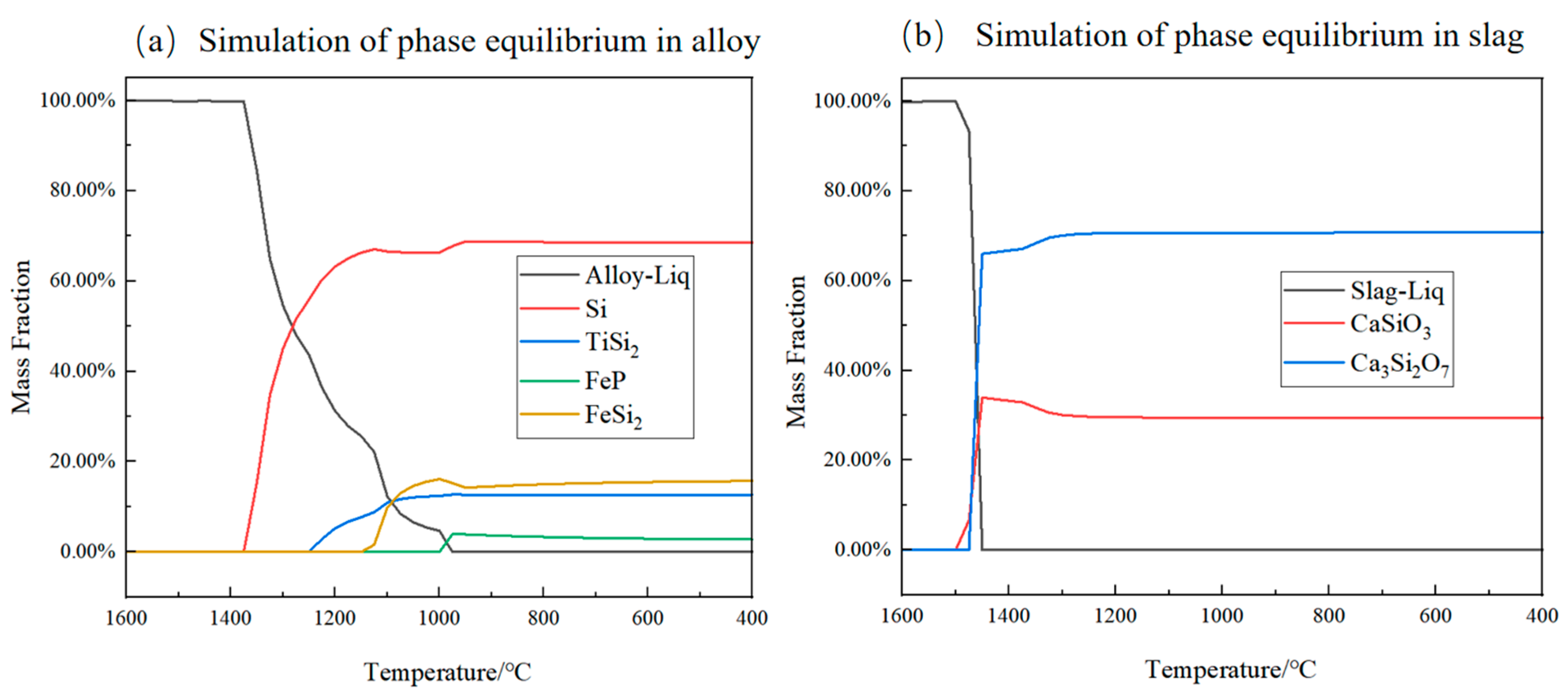
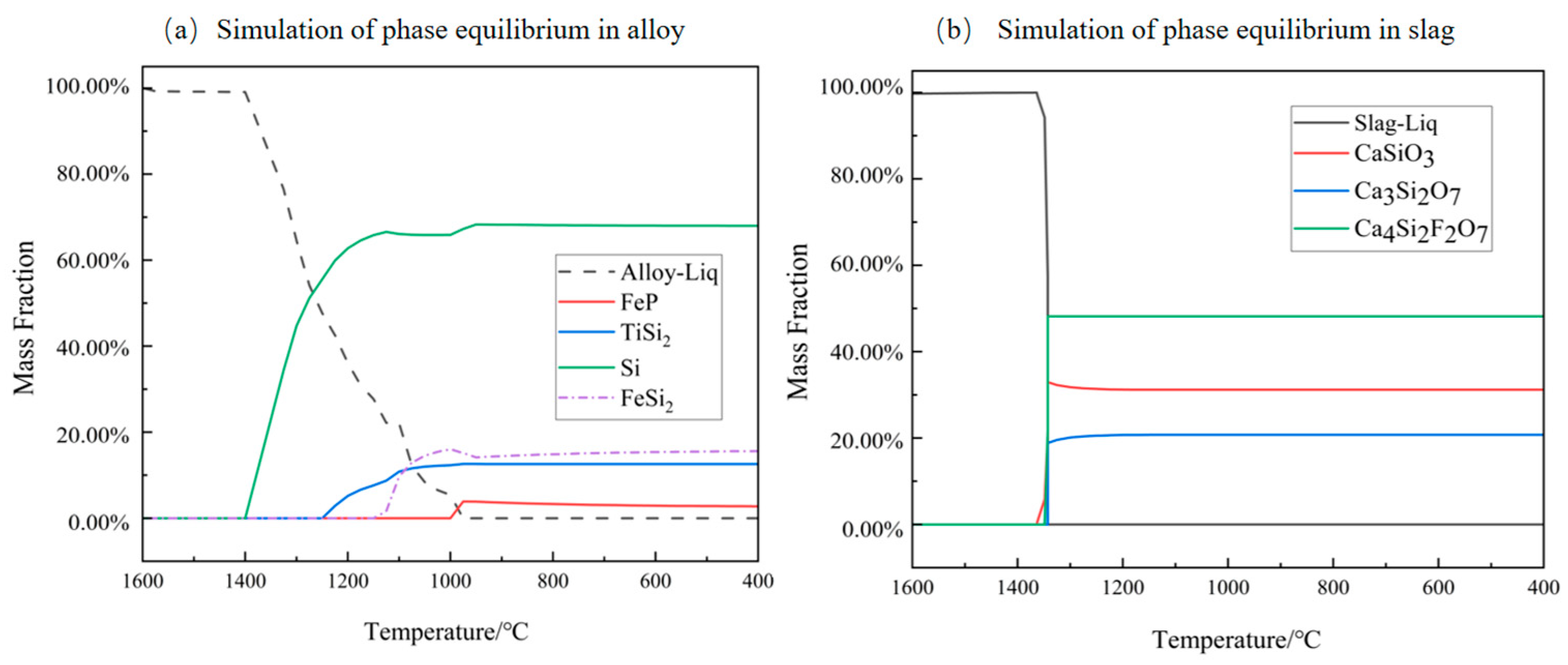
Thermodynamic theoretical calculation: Thermodynamic simulation calculations were conducted using FactSage software to predict the changes in the composition of thermodynamic equilibrium phases and liquid phases during the smelting process. These simulations allowed for the inference of various precipitated phases and their precipitation sequence (primary Si → TiSi2 → FeSi2 → FeP) in the alloy phase upon reaching thermodynamic equilibrium, thereby providing preliminary confirmation of the feasibility of this method.
(2)
Influence of slag composition: In this study, the initial exploration focused on the influence of refining a Si-10 wt. % Fe alloy using slags with varying compositions during the dephosphorization process (no slag addition, binary slag SiO2-TiO2, ternary slag SiO2-CaO-TiO2, and quaternary slag SiO2-TiO2-CaO-CaF2). The results indicated that when the quaternary slag system SiO2-TiO2-CaO-CaF2 was employed, the incorporation of CaF2 enhanced the slag’s fluidity, lowered its melting point, facilitated interfacial reactions, and ultimately led to the most efficient P removal.
(3)
TiO2 content: Based on the SiO2-TiO2-CaO-CaF2 system, the TiO2 content in the slag was varied within the range of 5–20 wt. %. As the TiO2 content increased, the P removal rate also showed an upward trend. However, due to the substantial decrease in primary silicon yield at higher TiO2 levels, the optimal TiO2 content was determined to be 10 wt. %. Under these conditions, utilizing a Si-10wt. %Fe alloy and a slag composition of 48 wt. %CaO-32 wt. %SiO2-10 wt. %TiO2-10 wt. %CaF2, a P removal rate of 96.8% was achieved.
(4)
Analysis of the dual impurity removal mechanism: Based on the theoretical calculations and experimental results, the removal of P in this study was primarily achieved through two mechanisms. A portion of P was removed via slag oxidation. Due to the high alkalinity of CaO and the oxygen potential of SiO2, P was oxidized into stable Ca3(PO4)2 at the slag–silicon interface. Secondly, the remaining phosphorus within the alloy was removed through reduction with TiO2. This process facilitated the migration of P to the Fe-Si-Ti ternary phase, where it was subsequently captured by TiSi2 formed during the reaction.
This study demonstrates the synergy between alloy refinement and slag oxidation, providing a scalable and energy-efficient approach for the production of solar-grade silicon. Future studies should explore industrial-scale parameter optimization and multiimpurity (e.g., boron) co-removal strategies.

Author Contributions

Conceptualization, J.L.; methodology, J.L. and Y.Z.; software, J.L.; investigation, Y.Z.; writing—original draft, J.L. and Y.Z.; writing—review and editing, J.L. and Q.Z.; supervision, Q.Z. All authors have read and agreed to the published version of the manuscript.

Funding

This work was supported by the Open Fund from the Key Laboratory for Ecological Metallurgy of Multimetallic Mineral (Ministry of Education), Northeastern University (NEMM2022002).

Data Availability Statement

The original contributions presented in this study are included in the article. Further inquiries can be directed to the corresponding author.

Conflicts of Interest

The authors declare no conflicts of interest.

References

  1. Ranjan, S.; Balaji, S.; Panella, R.A. Silicon solar cell production. Comput. Chem. Eng. 2011, 35, 1439–1453. [Google Scholar] [CrossRef]
  2. He, Y.F.; Ma, W.H.; Xing, A.M.; Hu, M.; Liu, S.; Yang, X.; Li, J.; Du, S.; Zhou, W. A review of the process on the purification of metallurgical grade silicon by solvent refining. Mater. Sci. Semicond. Process. 2022, 141, 106438. [Google Scholar] [CrossRef]
  3. Chen, H.; Morita, K.; Ma, X.; Chen, Z.; Wang, Y. Boron removal for solar-grade silicon production by metallurgical route: A review. Sol. Energy Mater. Sol. Cells 2019, 203, 110169. [Google Scholar] [CrossRef]
  4. Zhang, C.; Wei, K.; Zheng, D.; Ma, W.; Dai, Y. Phosphorus removal from upgraded metallurgical-grade silicon by vacuum directional solidification. Vacuum 2017, 146, 159–163. [Google Scholar] [CrossRef]
  5. Sekar, S.; Manickam, S.; Perumalsamy, R. Enhancement of the quality of mc-Si ingot grown by vacuum directional solidification furnace with growth rate increase reducing the cost of the wafer for PV application: Carbon and oxygen analysis. Vacuum 2025, 231, 113816. [Google Scholar] [CrossRef]
  6. Meteleva-Fischer, Y.V.; Yang, Y. Slag treatment followed by acid leaching as a route to Solar-Grade Silicon. Jom 2012, 64, 957–967. [Google Scholar] [CrossRef]
  7. Zhu, M.; Azarov, A.; Monakhov, E.; Tang, K.; Safarian, J. Phosphorus separation from metallurgical-grade silicon by magnesium alloying and acid leaching. Sep. Purif. Technol. 2020, 240, 116614. [Google Scholar] [CrossRef]
  8. Arman, H.; Stefan, A.; Michael, M. Boron removal from silicon melt by gas blowing technique. High Temp. Mater. Process. 2022, 41, 69–91. [Google Scholar]
  9. Lai, H.; Sheng, Z.; Li, J.; Xing, P.; Luo, X. Enhanced separation of phosphorus from metallurgical grade silicon by CaAl2Si2 phase reconstruction. Sep. Purif. Technol. 2018, 191, 257–265. [Google Scholar] [CrossRef]
  10. Huang, F.; Lu, Q.; Wu, M.; Zhao, L. Purification of metallurgical-grade silicon by Sn-Si solvent refining with different tin content. Silicon 2022, 14, 103–113. [Google Scholar] [CrossRef]
  11. Mei, J.; Yu, W.; Hou, P.; Xue, Y.; Xin, Y.; Yan, K. Purification of metallurgical grade silicon via the Mg-Si solvent refining and acid leaching process. Silicon 2020, 13, 341–350. [Google Scholar] [CrossRef]
  12. Li, Y.; Wu, J.; Ma, W.; Yang, B. Boron removal from metallurgical grade silicon using a refining technique of calcium silicate molten slag containing potassium carbonate. Silicon 2014, 7, 247–252. [Google Scholar] [CrossRef]
  13. Zhu, M.; Wu, G.; Azarov, A.; Monakhov, E.; Tang, K.; Müller, M.; Safarian, J. Effects of La2O3 addition into CaO-SiO2 slag: Structural evolution and impurity separation from Si-Sn alloy. Metall. Mater. Trans. B 2021, 52, 3045–3063. [Google Scholar] [CrossRef]
  14. He, Q.; He, N.; Yang, D.; Wu, J.; Wei, K.; Ma, W. Oxidation kinetics and mechanism of boron in metallurgical-grade silicon melt by CaO-SiO2 slag refining. Metall. Mater. Trans. B 2022, 53, 1841–1850. [Google Scholar] [CrossRef]
  15. Zhang, C.; Lai, H.; Zhang, Y.; Sheng, Z.; Li, J.; Xing, P.; Luo, X. Extraction of phosphorus from metallurgical grade silicon using a combined process of Si-Al-Ca solvent refining and CaO-CaF2 slag treatment. Sep. Purif. Technol. 2020, 232, 115954. [Google Scholar] [CrossRef]
  16. Cheng, Z.; Zhao, Q.; Tao, M.; Du, J.; Huang, X.; Liu, C. Preparation of FeCoNi medium entropy alloy from Fe3+-Co2+-Ni2+ solution system. Int. J. Miner. Metall. Mater. 2025, 32, 92–101. [Google Scholar] [CrossRef]
  17. Yan, Z.; Zhao, Q.; Han, C.; Mei, X.; Liu, C.; Jiang, M. Effects of iron oxide on crystallization behavior and spatial distribution of spinel in stainless steel slag. Int. J. Miner. Metall. Mater. 2024, 31, 292–300. [Google Scholar] [CrossRef]
  18. Wang, Z.; Ge, Z.; Liu, J.; Qian, G.; Du, B. The mechanism of boron removal from silicon alloy by electric field using slag treatment. Sep. Purif. Technol. 2018, 199, 134–139. [Google Scholar] [CrossRef]
  19. Chen, C.; Li, J.; Zuo, Q.; Ban, B.; Chen, J. Simultaneously removal of P and B from Si by Sr and Zr co-addition during Al-Si low-temperature solvent refining. Int. J. Miner. Metall. Mater. 2023, 30, 365–377. [Google Scholar] [CrossRef]
  20. Meteleva-Fischer, Y.V.; Yang, Y.; Boom, R.; Kraaijveld, B.; Kuntzel, H. Microstructure of metallurgical grade silicon during alloying refining with calcium. Intermetallics 2012, 25, 9–17. [Google Scholar] [CrossRef]
  21. Zhu, M.; Yue, S.; Wu, G.; Tang, K.; Xu, Y.; Safarian, J. P removal from Si by Si-Ca-Al alloying-leaching refining: Effect of Al and the CaAl2Si2 phase. Sep. Purif. Technol. 2021, 271, 118675. [Google Scholar] [CrossRef]
  22. Huang, L.; Danaei, A.; Thomas, S.; Xing, P.; Li, J.; Luo, X.; Barati, M. Solvent extraction of phosphorus from Si-Cu refining system with calcium addition. Sep. Purif. Technol. 2018, 204, 205–212. [Google Scholar] [CrossRef]
  23. Ren, Y.; Morita, K. Low-temperature process for the fabrication of low-boron content bulk Si from Si–Cu solution with Zr addition. ACS Sustain. Chem. Eng. 2020, 8, 6853–6860. [Google Scholar] [CrossRef]
  24. Liu, Y.; Jiang, S.; Wang, X.; Kong, J.; Xing, P.; Zhuang, Y.; Luo, X. Synthesis and separation of Si-Fe alloy to produce high-purity silicon. J. Mater. Res. Technol. 2019, 8, 4470–4476. [Google Scholar] [CrossRef]
  25. Khajavi, L.T.; Morita, K.; Yoshikawa, T.; Barati, M. Removal of boron from silicon by solvent refining using ferrosilicon alloys. Metall. Mater. Trans. 2015, 46, 615–620. [Google Scholar] [CrossRef]
  26. Taposhe, G.I.A.; Khajavi, L.T. Removal of phosphorus from Si-Fe alloy by CaO-Al2O3-SiO2-Na2O slag refining. JOM 2021, 73, 729–735. [Google Scholar] [CrossRef]
  27. Esfahani, S.; Barati, M. Purification of metallurgical silicon using iron as impurity getter, part II: Extent of silicon purification. Met. Mater. Int. 2011, 17, 1009–1015. [Google Scholar] [CrossRef]
  28. Esfahani, S.; Barati, M. Purification of metallurgical silicon using iron as an impurity getter part I: Growth and separation of Si. Met. Mater. Int. 2011, 17, 823–829. [Google Scholar] [CrossRef]
  29. Deng, X.; Li, S.; Wen, J.; Wei, K.; Zhang, M.; Yang, X.; Ma, W. Mechanism of enhancing phosphorus removal from metallurgical grade silicon by Si-Fe-Ti phase reconstruction. Metall. Mater. Trans. B 2021, 52, 625–632. [Google Scholar] [CrossRef]
  30. Taposhe, G.I.A.; Khajavi, L.T. Thermodynamics of impurities removal from Si–Fe alloy by CaO–Al2O3–SiO2–Na2O slag refining. Metall. Mater. Trans. B 2022, 53, 4019–4028. [Google Scholar] [CrossRef]
  31. Li, M.; Utigard, T.; Barati, M. Removal of boron and phosphorus from silicon using CaO-SiO2-Na2O-Al2O3 flux. Metall. Mater. Trans. B 2014, 45, 221–228. [Google Scholar] [CrossRef]
  32. Hosseinpour, A.; Tafaghodi Khajavi, L. Phosphorus removal from Si-Fe alloy using SiO2-Al2O3-CaO Slag. Metall. Mater. Trans. B 2019, 50, 1773–1781. [Google Scholar] [CrossRef]
  33. Sakiani, H.; Tabaian, S.H.; Chen, J.; Li, J.; Ban, B. Investigating boron and phosphorus removal from silicon by Si-Ti and Si-Ti-Fe alloying systems. Sep. Purif. Technol. 2020, 250, 117227. [Google Scholar] [CrossRef]
  34. Gu, H.Z.; Cao, J.; Wu, J.J.; Wei, K.; Ma, W. A novel method for preparing Si–Ti alloy by co-reduction of silicon slag and Ti-bearing blast furnace slag. Metall. Mater. Trans. B 2023, 54, 2815–2823. [Google Scholar] [CrossRef]
  35. Park, H.J.; Min, J.D.; Song, S.H. The effect of CaF2 on the viscosities and structures of CaO-SiO2(-MgO)-CaF2 slags. Metall. Mater. Trans. B 2002, 33, 723–729. [Google Scholar] [CrossRef]
  36. Ju, J.; Yang, K.; Zhu, Z.; Gu, Y.; Chang, L.Z. Effect of CaF2 and CaO/Al2O3 on viscosity and structure of TiO2-bearing slag for electroslag remelting. Iron Steel Res. Int. 2021, 28, 1541–1550. [Google Scholar] [CrossRef]
  37. Bale, C.W.; Bélisle, E.; Chartrand, P.; Decterov, S.A.; Eriksson, G.; Gheribi, A.E.; Hack, K.; Jung, I.H.; Kang, Y.B.; Melançon, J.; et al. Reprint of: FactSage thermochemical software and databases. Calphad 2016, 55, 1–19. [Google Scholar] [CrossRef]
  38. Shahbazian, F.; Sichen, D.; Mills, K.C.; Seetharaman, S. Experimental studies of viscosities of some CaO-CaF2-SiO2 slags. Ironmak. Steelmak. 2013, 26, 193–199. [Google Scholar] [CrossRef]
  39. Shahbazian, F. Experimental studies of the viscosities in the CaO-FeO-SiO2-CaF2 slag. Scand. J. Metall. 2001, 30, 302–308. [Google Scholar] [CrossRef]
  40. Thomas, S.; Huang, L.; Barati, M. A review of slag refining of crude Silicon. JOM 2020, 73, 260–281. [Google Scholar] [CrossRef]
  41. Putera, P.D.A.; Avarmaa, L.K.; Petrus, H.T.; Chen, J.; Brooks, G.A.; Rhamdhani, M.A. Multistage refining of silicon using CaO–SiO2–Al2O3 and CaO–SiO2–MgO slags. J. Sustain. Metall. 2025, 11, 895–907. [Google Scholar] [CrossRef]
Figure 1. Flow diagram of the experiment.
Metals 15 00668 g001
Figure 2. Simulation results of the equilibrium phase of 36 wt. %SiO2-54 wt. %CaO-10 wt. %TiO2 slag coupled with the Si-10 wt. %Fe-1 wt. %P alloy.
Metals 15 00668 g002
Figure 3. Simulation results of the equilibrium phase of 32 wt. %SiO2-48 wt. %CaO-10 wt. %TiO2-10 wt. %CaF2 slag coupled with the Si-10 wt. %Fe-1 wt. %P alloy.
Metals 15 00668 g003
Figure 4. The theoretical precipitation amount of the P-rich phase and primary silicon.
Metals 15 00668 g004
Figure 5. SEM images of the refined alloy refined by co-refining the Si-Fe alloy with different slags: (a) S1; (b) S2; (c) S3; (d) S4.
Metals 15 00668 g005
Figure 6. Map scanning of the refined alloy of S4.
Metals 15 00668 g006
Figure 7. Microstructures of the refined alloys of S5 (a) and S7 (b).
Metals 15 00668 g007
Figure 8. XRD pattern of the refined alloy sample.
Metals 15 00668 g008
Figure 9. XRD pattern of the refined slag sample.
Metals 15 00668 g009
Figure 10. The distribution ratio of P between slag/silicon LP1, the distribution ratio between alloy/silicon LP2, and the residual P content in silicon after pickling: (a) different slag compositions; (b) different TiO2 contents.
Metals 15 00668 g010
Figure 11. The residual P content in silicon and the P removal rate: (a) changes in slag composition; (b) changes in TiO2 content in the slag.
Metals 15 00668 g011
Figure 12. Reaction mechanism diagram of a Si-Fe alloy—slag refining for P removal.
Metals 15 00668 g012
Table 1. Experimental conditions in the present experiments.
No.Slag Composition (wt. %)
SiO2TiO2CaOCaF2
S10000
S2901000
S33610540
S432104810
S53455110
S630154510
S728204210
Table 2. EDS analysis of S1–S4 samples, corresponding to Figure 5.
PointSiFeTiPCaPossible Phases
wt. %at. %wt. %at. %wt. %at. %wt. %at. %wt. %at. %
1#54.5269.4642.5227.13-- 2.963.40-- FeSi2
2#53.4068.9644.8429.170.470.361.291.51-- FeSi2
3#41.9256.7629.5820.0627.0321.391.411.720.060.06FeSi2Ti
4#58.4870.670.630.3840.6928.740.170.190.030.03TiSi2
5#55.5668.549.806.0633.5524.191.021.140.080.07Si64.3Fe7.4Ti28.3
6#41.7656.3929.2019.7526.8621.202.172.650.010.009FeSi2Ti
Table 3. EDS analysis of samples, corresponding to Figure 7.
PointSiFeTiPPossible Phases
wt. %at. %wt. %at. %wt. %at. %wt. %at. %
1#46.5163.0852.1235.410.370.291.001.22FeSi2
2#31.9746.3836.6926.1929.0825.502.252.93FeSi2Ti
3#99.3899.670.340.170.280.16----Si
4#49.9463.145.133.2543.9035.451.021.16TiSi2
5#48.2961.6211.757.5137.3427.852.623.02Si64.3Fe7.4Ti28.3
6#32.8547.1635.5425.1028.5823.833.033.90FeSi2Ti
7#100100------------Si
Table 4. XRF results of the refined slags.
No. Element Content (wt. %)
SiCaFeTiPOF
S246.13--0.320.170.0153.37--
S323.0634.940.080.220.0541.65--
S421.0031.990.510.840.0638.976.63
S519.8035.240.830.250.1639.044.68
S619.7635.300.690.420.0838.325.43
S719.9335.080.270.580.1038.295.75
Table 5. The variation of the standard Gibbs free energy of possible reactions in the experimental system with temperature.
No.Reactions△Gθ (J/mol)Temp. (°C)
(1)[P] + 5/2Si + 3/2CaO + 5/4TiO2 = 1/2Ca3(PO4)2 + 5/4TiSi278.89T − 433,055.4800–1600
(2)[P] + 5/2Si + 3/2CaO + 5/4TiO2 + 5/4Fe = 1/2Ca3(PO4)2 + 5/4FeSi2 + 5/4Ti98.45T − 122,218.6800–1600
Disclaimer/Publisher’s Note: The statements, opinions and data contained in all publications are solely those of the individual author(s) and contributor(s) and not of MDPI and/or the editor(s). MDPI and/or the editor(s) disclaim responsibility for any injury to people or property resulting from any ideas, methods, instructions or products referred to in the content.

