Article

Effect of Scanning Speed on Wear and Corrosion Behaviors of High-Speed Laser-Cladded Cu-TiC Coating

School of Mechanical Engineering, Jiangsu University of Science and Technology, Changhui Road, Dantu District, Zhenjiang 212003, China
*
Author to whom correspondence should be addressed.
Metals 2025, 15(6), 641; https://doi.org/10.3390/met15060641
Submission received: 2 May 2025 / Revised: 31 May 2025 / Accepted: 4 June 2025 / Published: 9 June 2025
(This article belongs to the Section Corrosion and Protection)

Abstract

In response to the performance requirements of ship conductive rings in the coupled environment of high salt spray, high humidity, and mechanical wear in the ocean, a Cu-TiC composite coating was prepared on the surface of 7075 aluminum alloy by using the high-speed laser cladding (HLC) technology. The influence laws of the scanning speed (86.4–149.7 mm/s) on the microstructure, tribological properties, and corrosion resistance of the coating were explored. The results show that the scanning speed significantly changes the phase composition and grain morphology of the coating by regulating the thermodynamic behavior of the molten pool. At a low scanning speed (86.4 mm/s), the CuAl2 phase is dominant, and the grains are mainly columnar crystals. As the scanning speed increases to 149.7 mm/s, the accelerated cooling rate promotes an increase in the proportion of Cu2Al3 phase, refines the grains to a coexisting structure of equiaxed crystals and cellular crystals, and improves the uniformity of TiC particle distribution. Tribological property analysis shows that the high scanning speed (149.7 mm/s) coating has a 17.9% lower wear rate than the substrate due to grain refinement and TiC interface strengthening. The wear mechanism is mainly abrasive wear and adhesive wear, accompanied by slight oxidative wear. Electrochemical tests show that the corrosion current density of the high-speed cladding coating is as low as 7.36 × 10⁻⁷ A·cm−2, and the polarization resistance reaches 23,813 Ω·cm2. The improvement in corrosion resistance is attributed to the formation of a dense passivation film and the blocking of the Cl diffusion path. The coating with a scanning speed of 149.7 mm/s exhibits optimal wear-resistant and corrosion-resistant synergistic performance and is suitable for the surface strengthening of conductive rings in extreme marine environments. This research provides theoretical support for the process performance regulation and engineering application of copper-based composite coatings.

1. Introduction

Ship conductive rings, as the core components of the power transmission system, are exposed to the harsh marine environment with high salt spray, high humidity, and mechanical wear for a long time. Their surface coating needs to have excellent electrical conductivity, corrosion resistance, and wear resistance simultaneously [1,2]. Copper-based coatings are widely used due to their high electrical conductivity, but pure copper has low hardness and poor wear resistance [3,4]. Under sliding friction conditions, severe abrasive wear is prone to occur, resulting in increased contact resistance and signal transmission failure [5]. Furthermore, the penetration of chloride ions in the marine environment can induce local corrosion of the coating, accelerate the peeling of the coating, and threaten the long-term stable operation of the equipment [6,7]. Therefore, the development of high-performance copper-based composite coatings suitable for conductive rings of ships is of great engineering significance.
High-speed laser cladding (HLC) is a further development of conventional laser cladding (LC) technology, which has the advantages of high deposition efficiency and good coating molding quality, and it can realize the surface strengthening of non-ferrous metal materials such as Cu, Al, and Fe [8,9,10]. Among them, many studies have been conducted on the effect of scanning speed on the microstructure, tribology, and corrosion properties of high-speed laser cladding coatings. Wang et al. [11] compared the corrosion performance of Fe-based amorphous coatings with different scanning speeds and found that the increase in scanning speed was beneficial for the increase in amorphous phase content in the coating and the improvement of corrosion resistance. Gan et al. [12] prepared a Cu-Sn coating on a Ti6Al4V alloy by HLC, exhibiting superior plasticity and finer grain size than the pure Cu coating.
In recent years, preparing copper-based composites by introducing ceramic reinforcing phases (such as SiC, TiC, and Al2O3) has become an effective way to improve comprehensive performance [13,14]. Among them, TiC is regarded as an ideal reinforcing phase due to its high hardness, good thermal stability, and thermal expansion coefficient similar to that of the copper matrix [15]. However, traditional preparation techniques such as thermal spraying and powder metallurgy are prone to cause problems such as the oxidation of TiC particles, weakened interfacial bonding, and high porosity during high-temperature processing.
Yu et al. [16] achieved the synergistic regulation of grain refinement and enhanced phase distribution of nickel-based composite coatings by optimizing the process parameters of high-speed laser cladding, significantly improving the hardness and wear resistance of the coatings. Ren et al. [17] regulated the thermodynamic behavior of medium-entropy alloy coatings based on HLC technology, effectively suppressing crack defects and strengthening the precipitation of carbide phases, significantly improving the tribological properties of the coatings. Zhou et al. [18] systematically analyzed the strengthening mechanism of sub-micron ceramic particles under the HLC process, clarifying that it simultaneously enhances the wear resistance and electrochemical corrosion resistance of the coating through dispersion strengthening and interface stability optimization. Liu et al. [19] innovatively utilized the in situ reaction mechanism of HLC to construct high-entropy boride ceramic coatings on the surface of titanium alloys. Its super-hard property and dense structure endow the coating with excellent wear resistance and interfacial bonding strength. Current research mostly focuses on the influence of the HLC process on the microstructure and properties of iron-based and nickel-based coatings, while there are still deficiencies in the research on the Cu-TiC system. Meanwhile, the scanning speed directly affects the solidification behavior of the molten pool and the distribution state of TiC particles. However, the influencing mechanism of the scanning speed on the microstructure and properties of Cu-TiC coatings is still unclear.
In this paper, aiming at the working condition requirements of the conductive rings of ships, a Cu-TiC composite coating was prepared on the surface of 7075 aluminum alloy by using high-speed laser cladding technology. Meanwhile, the influence law of scanning speed on the microstructure, friction and wear performance, and corrosion resistance of the coating was studied. The phase composition and elemental distribution were analyzed by XRD and SEM/EDS, and combining these with hardness tests, friction and wear experiments, and electrochemical tests, the regulation mechanism of scanning speed on the multi-scale structure and properties of the coating was clarified. This paper provides theoretical references and a process optimization basis for surface strengthening of key components of marine equipment.

2. Experimental Methods

2.1. Material Preparation

A 5% mass fraction of TiC powder (Shanghai Maoguo Nano Technology Co., Ltd., Shanghai, China) with a particle size distribution of approximately 20 μm (purity ≥ 99.9 wt%) was mixed with Cu powder (Chengdu Ketailong Alloy Co., Ltd., Chengdu, China) with a particle size distribution of approximately 25 μm (purity ≥ 99.9 wt%) using electronic scales. Then, the evenly mixed Cu-TiC powders were placed in a 101-B-type blast drying oven (Shaoxing Su Bo Instrument Co., Ltd., Shaoxing, China) and subjected to a temperature of 120 °C for 2 h. Before the high-speed laser cladding (HLC) test, the 7075-aluminum substrate surface with the size of Ø55 × 300 mm was ground using the 240# SiC sandpaper to remove its oxide and oil stain, and the chemical elements are listed in Table 1.
The HLC experiment was performed using an RFL-C2000X-type fiber laser device (Wuhan Raycus Fiber Laser Technologies Co., Ltd., Wuhan, China) with a laser wavelength of 1080 nm and a spot diameter of 3 mm using the coaxial feeding method, where the Ar (purity ≥ 99.999%) with 15 L/min was used as the shielding gas to prevent the coating from oxidation, as shown in Figure 1a. The relevant HLC process parameters are listed in Table 2.
After the experiment, the fabricated Cu-TiC coating was cut using a wire cutting machine, ground with SiC sandpaper with grit sizes of 240, 600, 800, 1000, 1200, 1500, and 2000# in turn; each sandpaper was used for approximately 10 min, and the sanding direction was also changed following each grit modification to mitigate scratch formation. Then the coating was mechanically polished with 1.5 μm diamond grinding paste using the MDP-2-type metallographic grinding and polishing machine (Shanghai Wanheng Precision Instrument Co., Ltd., Shanghai, China) to obtain the scratch-free surface to be tested. Subsequently, the polished Cu-TiC coating was etched with 4% HNO3 solution to reveal the microstructure.

2.2. Microstructure Characterization

The phase composition of the coating was determined using a Bruker D8 ADVANCE diffractometer (XRD) with the Cu Kα radiation (λ = 1.5406 Å) at 40 kV and 40 mA, a scanning range of 20–90°, a scanning rate of 10°/min, and a scanning step size of 0.01°. The microstructure and elemental distribution of the coating were observed using a MAIA3-type field emission electron microscope (FESEM, Tescan, Brno, Czech Republic) and its equipped energy disperse spectroscopy (EDS). The HVS-1000A-type hardness tester (Laizhou Huayin Test Instrument Co., Ltd., Laizhou, China) was chosen for the coating surface hardness measurement, and the test parameters are shown as follows: a normal load of 300 g; and a pressure holding time of 10 s.

2.3. Wear Test

The wear test was conducted using a self-made friction–wear tester to simulate the actual service conditions of slip rings, as depicted in Figure 1b. The parameters of the tester were as follows: a rotational speed of 250 r/min; normal load of 5 N; working current of 25 A; and wear time of 30 min. Additionally, the Ø150 × 10 mm E-22 graphite was selected for the friction pair. Each wear test was repeated three times to ensure the test accuracy, and the wear rate (W) was calculated as follows:
W = ∆w/L
L = 2 π · R · n · T
where Δw is the wear loss measured with an analytical balance (mg); L represents the total wear distance (m); R denotes the diameter of the friction pair (m); n is the rotation speed (r·min−1); and T expresses the test time (min). After the friction–wear test, the worn track and elemental distribution of coating were further analyzed using an SEM and EDS.

2.4. Electrochemical Measurement

Before the test, the coatings were exposed to an area of 1 cm2 in the 3.5 wt% NaCl solution, and the other region was sealed by epoxy resin. The electromechanical measurements of the coating were conducted using a DH7006 electrochemical workstation (Jiangsu Donghua Analytical Instrument Co., Ltd., Jingjiang, China) using a classic three-electrode electrochemical system, where the coating, platinum plate, and saturated calomel electrode (SCE) were used as the working electrode, counter electrode (CE), and reference electrode, respectively. The electrochemical impedance spectrum (EIS) measurement was conducted at the potential amplitude of 10 mV in the frequency range of 10−2 to 105 Hz, and the dynamic potential polarization curve (PPC) test was performed at the scanning speed of 1 mV/s in the range of −0.7 to 1 Vocp. To ensure the accuracy of the data, each coating with different scanning speeds was repeated at least three times.

3. Results and Discussion

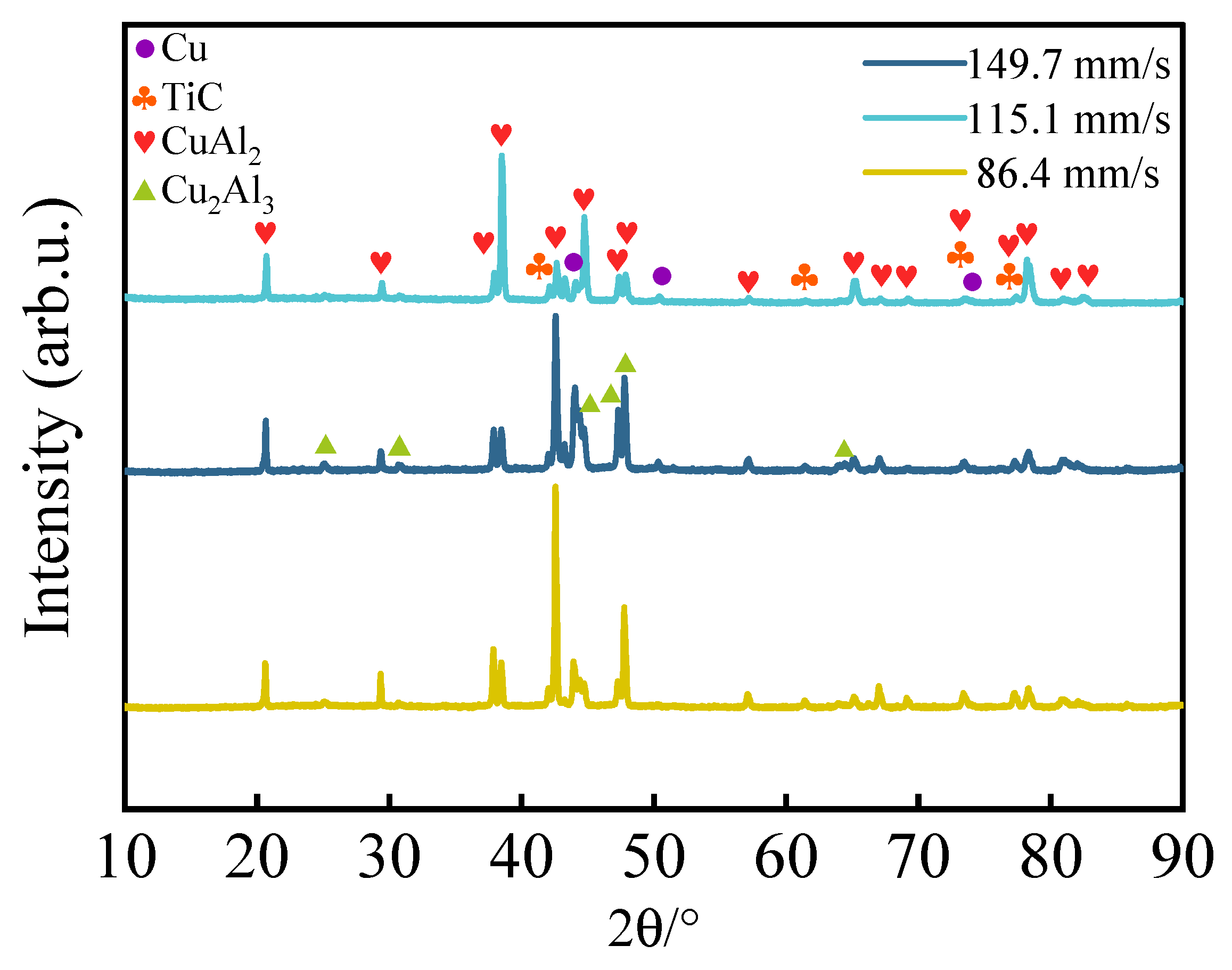
3.1. Phase and Microstructure
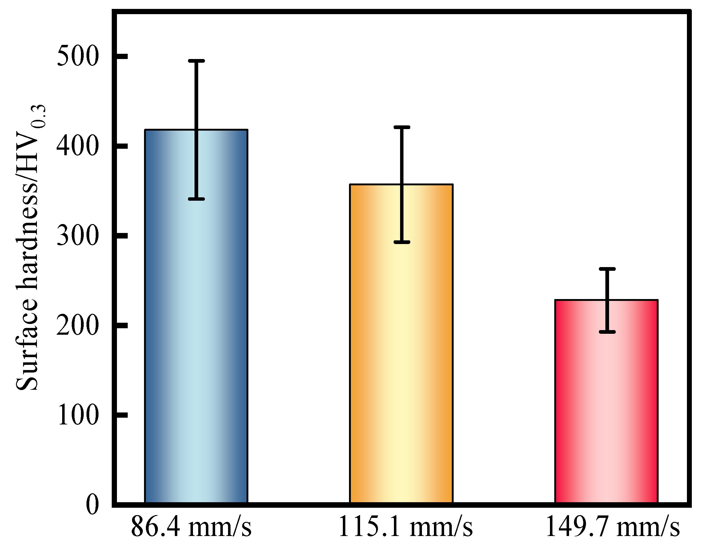
Figure 2 presents the XRD patterns of the coatings. The XRD spectra reveal that the coatings prepared at different scanning speeds were composed of Cu (PDF#04-004-8452), TiC (PDF#04-002-0155), CuAl2 (PDF#04-003-3349), and Cu2Al3 (PDF#04-001-0923) phases and the corresponding space groups of Fm-3m (225), Fm-3m (225), I4/mcm (140), and P-3m1 (164), respectively. The CuAl2 and Cu2Al3 phases are common intermetallic compounds in Cu-Al composite materials, indicating the coatings contained a high content of Al due to substrate dilution [19]. The low peak intensity of TiC in the XRD pattern is attributed to its low content in the coating. It is also observed that as the scanning speed increased from 86.4 to 149.7 mm/s, the intensity of the CuAl2 peak decreased, while that of the Cu2Al3 peak exhibited an increasing trend.
The variation in phase composition with scanning speed can be attributed to the influence of thermal conditions on phase formation [20]. At low scanning speeds, the prolonged interaction time between the laser beam and substrate material resulted in slower cooling rates. This provided sufficient time for the thermodynamically stable CuAl2 phase to form under these conditions. However, as the scanning speed increased, the reduced laser interaction time led to faster heating and cooling rates. During rapid cooling, the formation of CuAl2 was suppressed due to its relatively slower nucleation and growth kinetics. In contrast, the Cu2Al3 phase demonstrated either a higher nucleation rate or greater thermodynamic stability during rapid cooling, making it more favorable at higher scanning speeds.
Figure 3 illustrates the morphologies and mapping analysis of Cu-TiC coating surfaces at the different scanning speeds. As the scanning speed increased, the microstructure of the cladding layer underwent significant changes, and the thickness and defects (pore and crack) of the coating also exhibited a decreasing trend. The measured values of coating thickness were 539, 452, and 313 μm at scanning speeds of 86.4, 115.1, and 149.7 mm/s, respectively. At a scanning speed of 86.4 mm/s, the coating primarily consisted of columnar crystals and cellular crystals. This is attributed to the slower cooling rate, which allowed atoms sufficient time for diffusion, thereby facilitating the formation of columnar and cellular crystal structures. The cooling rate is the product value of the temperature gradient ( G s ) and solidification rate ( R s ) and affects the scale of coating solidification in microstructures. The faster the cooling rate is, the smaller the dendrite size of the coating is. On the other hand, the microstructure morphology of the coating changed from columnar crystal → cellular crystal → equiaxed crystal as the cooling rate decreased. Equiaxed crystals are defined as those exhibiting identical growth rates in multiple directions, resulting in symmetrical forms such as cubes and possessing essentially isotropic physical properties. Columnar crystals are characterized by preferential growth in a specific direction, leading to columnar, acicular, or fibrous morphologies. Cellular crystals are distinguished by the presence of a cellular structure either internally or on their surface. The cooling rate is given as follows [21]:
G s = T · n
R s = V s · cos θ s
where G s is the temperature gradient; T denotes the value temperature variation; n displays the unit normal vector of the liquidus front; V s represents the scanning speed of the laser; θ s denotes the angle between the scanning speed and the normal vector of the solidification interface.
When the scanning speed increased from 86.4 mm/s to 149.7 mm/s, the growth of columnar crystals was suppressed, and equiaxed crystals began to appear due to the accelerated cooling rate. This indicates that atomic diffusion was restricted, while the nucleation rate increased. Consequently, the microstructure of the coating was predominantly composed of equiaxed crystals and cellular crystals. Rapid cooling restricted grain growth, resulting in fine equiaxed crystals and cellular crystals. Elemental distribution analysis revealed that Ti and C were uniformly distributed across the coating, whereas the distribution of Cu and Al highlights the increased segregation behavior of elemental composition as the cooling rate accelerated.

3.2. Hardness

Figure 4 showcases the average hardness of the Cu-TiC coating surfaces at different scanning speeds. The average hardness values of coating surfaces at scanning speeds of 86.4, 115.1, and 149.7 mm/s were 401, 346, and 176 HV0.3, respectively. The results show that the hardness of the Cu-TiC coatings decreased with the increase in scanning speed, which is attributed to the content change in CuAl2 and Cu2Al3 (Figure 2). The observed hardness reduction originated from the interaction between phase transformation dynamics and microstructural evolution. The increased scanning speed induced non-equilibrium solidification conditions that thermodynamically suppressed the formation of the high-hardness and stable equilibrium phase CuAl2 while promoting the precipitation of the low-hardness phase Cu2Al3, thereby diminishing the overall hardness of the Cu-TiC coating system [22]. Although grain boundary refinement achieved by increasing the scanning speed could improve the hardness through the Hall–Petch mechanism, the microstructure optimization could not offset the significant decrease in hardness caused by the decrease in the content of the reinforcing phase CuAl2 within the coating.

3.3. Wear Performance

3.3.1. COF and Wear Rate

Figure 5a shows the COFs vs. sliding time of Cu-TiC coatings prepared at different scanning speeds. The friction between the coating and the friction pair was due to the contact between their respective micro-convex bodies [23]. The contact area of micro-convex bodies was small during the running-in period, thus resulting in the COF curves of the substrate and coating showing an upward trend [24]. The contact area of micro-convex bodies increased as the friction time continued, and the COF curves reached the stable wear period, where they fluctuated around a fixed value. The COFs of the coating at scanning speeds of 86.4, 115.1, and 149.7 mm/s were 0.088, 0.081, and 0.080, respectively.
Figure 5b illustrates the wear rates of Cu-TiC coatings with different scanning speeds. The Cu-TiC coating at a scanning speed of 86.4 mm/s had the highest hardness, but its wear resistance was the worst. This inverse relationship between hardness and wear originates from pre-existing cracks on the coating propagating under cyclic stresses, accelerating material removal [25]. In this case, when the scanning speed of the coating increased to 149.7 mm/s, the wear rate of the Cu-TiC coating was 2.3 × 10⁻³ mg·m−1, which was 17.9% lower than that of the substrate.

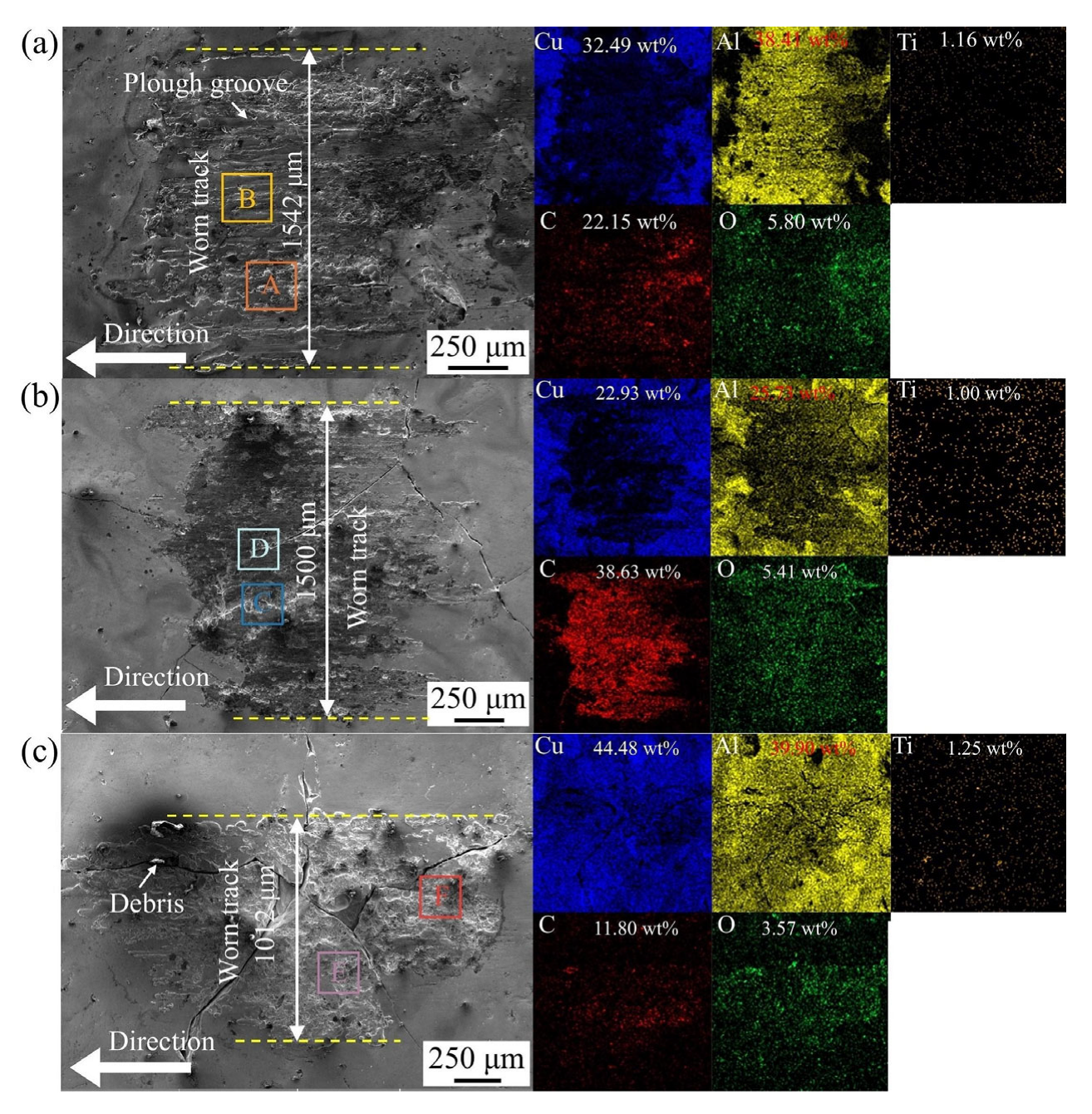
3.3.2. Mapping Analysis of Worn Track on Coatings

Figure 6 presents the morphologies and mapping analysis of worn tracks on Cu-TiC coatings at different scanning speeds. The content of Cu and Al on the worn track was lower than that of unworn coating, showing the coating loss from these elements. Conversely, the content of O and C on the worn track showed the opposite trend. The increase in O originated from the frictional heat caused by the adhesion, shear, and collision of micro-convex bodies between the worn track and friction pair [26]. The increase in C was due to the material transfer between the friction pair (graphite) and the coating under the action of shear stress. With the increase in scanning speed, the decrease in C content and the increase in Cu on the worn track indicated a reduction in material transfer, and the widths of the worn tracks also showed a decreasing trend.

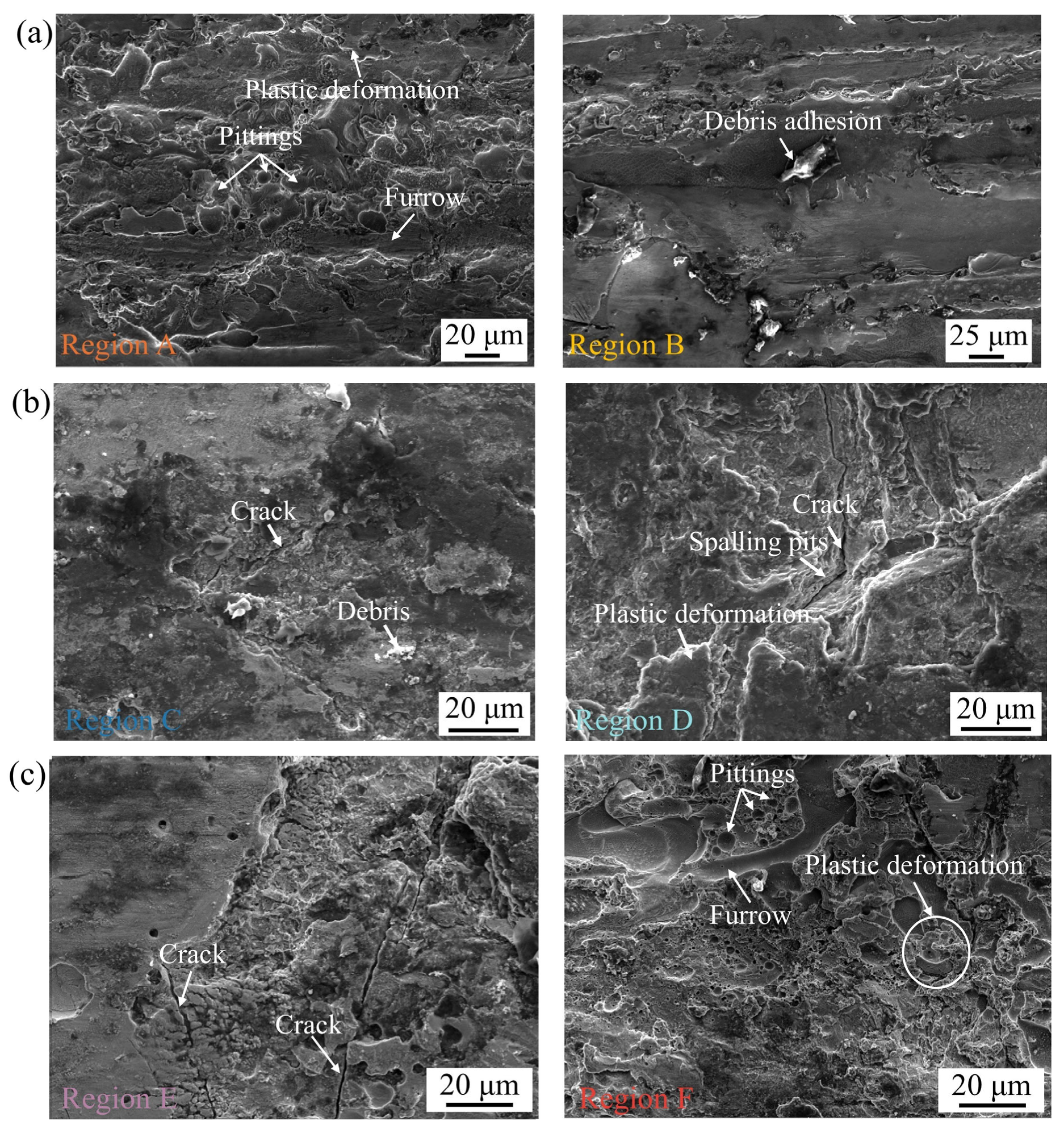
3.3.3. Morphologies of Worn Track on Coatings

Figure 7a showcases the worn track morphologies of Cu-TiC coating fabricated at a scanning speed of 86.4 mm/s. During the friction process, the combination of shear and compressive stresses resulted in the plastic deformation features on the wear surface [27]. Meanwhile, frictional heating and compressive loading promoted adhesive interactions, inducing cold welding phenomena. When interfacial stresses surpassed the adhesive layer’s yield strength, material transfer and adhesion pits occurred. The part of wear debris generated in the friction process was adhered to the worn track by cold welding, while the rest of the debris was compacted into the worn track by the friction pair in the form of three-body abrasive wear. Under the action of shear stress, this wear debris plowed the coating surface, generating the characteristics of furrows. Therefore, the plastic deformation and the abrasive cutting caused the TiC on the worn track to peel off, which acted as hard abrasive particles, aggravating the wear loss [28]. Notably, the neighboring areas where cracks already existed during the coating manufacturing process were more prone to spalling under shear stress, leading to more material loss.
Figure 7b,c display the worn track morphologies of Cu-TiC coating at scanning speeds of 115.1 and 149.7 mm/s, respectively. The observed microcracks indicate that the worn track underwent repeat friction and stress action during the friction process, forming the work-hardened areas. This work-hardening increases the surface hardness of worn tracks, significantly improving wear resistance and suppressing plastic deformation [29,30]. Consequently, the TiC on the worn track was less likely to peel off, improving the coating’s load-bearing capacity and reducing the wear loss. However, the work-hardened region also cracked and peeled off in the form of flakes with the continuation of friction time, resulting in flake-like spallation when the cracks extended to a certain size.

3.3.4. Wear Mechanism

Figure 8 reveals the multi-scale wear failure mechanism of the Cu-TiC coatings at different scanning speeds. The coating wear trajectory presented typical plowing grooves, micro-area spalling pits, plastic deformation ridges, and flaky adhesive debris (Figure 8), indicating that its failure behavior was jointly dominated by abrasive wear and adhesive wear [31]. Abrasive wear is the shedding of hard TiC particles from the substrate under the action of shear stress [32]. The free TiC particles act as “micro-cutting tools”, rubbing against the coating surface along the movement direction of the friction pair to form parallel plowing grooves. The coating with a low scanning speed (86.4 mm/s) expanded due to the original microcracks (Figure 3(a1)) under cyclic stress, accelerating the stripping of the hard phase, resulting in an increase in abrasive density and a rise in wear rate. Adhesive wear is induced by frictional heat to soften the surface layer of the coating [24,33]. Under the action of contact pressure, a cold welding effect occurred between the Cu substrate and the graphite friction pair, forming an adhesive joint. As the sliding continued, the fracture of the nodes generated flaky wear debris, which accumulated at the edge of the wear trajectory, intensifying material transfer and surface roughening.
In addition, it has a synergistic effect on oxidative wear. The EDS surface scan results show that the wear trajectory was enriched with oxygen elements (Figure 6), and the surface layer of the wear mark had a Cu2O/CuO oxide film. This oxide film can reduce the direct contact of metals in the initial stage, but its brittle characteristics lead to cracking under the action of shear force [34]. Broken oxide particles participate in three-body wear and aggravate surface damage. It is notable that as the scanning speed increased from 86.4 mm/s to 149.7 mm/s, the grains of the coating were refined, significantly inhibiting the stripping of the hard phase and the size of the bonding nodes. This enabled the wear mechanism to transform from a severe grain-dominated type to a mild adhesive-oxidation synergistic type.

3.4. Electrochemical Corrosion Behavior

3.4.1. PPC

The potentiodynamic polarization curves of Cu-TiC coatings at different scanning speeds are presented in Figure 9, and the relevant fitting data from the Tafel extrapolation method is listed in Table 3 [35]. The polarization resistance (Rp) is calculated as follows:
R p = β a · β c i c o r r · 2 . 303 ( β a + β c )
where βa and βc denote the anode slope and cathode slope (mV·dec−1), respectively; and icorr is the corrosion current density (A·cm−2). The low value of Rp reflects that the electrochemical reaction is easier to process, which is inversely proportional to the corrosion current density (icorr) [36,37]. Furthermore, the difference between the anode slope and the cathode slope reflects the asymmetry of the electrochemical reaction. At the scanning speed of 86.4 and 115.1 mm/s, the anode slope was greater than the cathode slope, indicating that the oxidation reaction of the coating was a rate-controlling step in the corrosion process. When the scanning speed increased to 149.7 mm/s, the cathode slope was greater than the anode slope, meaning that the corrosion process was controlled by the cathode slope. The corrosion potential (Ecorr) of the coating shifted positively with the increase in scanning speed, while icorr continuously decreased. A higher corrosion potential indicates a lower corrosion tendency, reducing the corrosion susceptibility of the coating; meanwhile, the corrosion current density reflects the kinetics of the corrosion reaction, so a lower current density corresponds to a slower corrosion rate and enhanced corrosion resistance [38,39]. Cl tended to preferentially attack the CuAl2 phase in the Cu-Al composite materials, accelerating its dissolution. The increase in scanning speed could reduce the CuAl2 content of coating and decrease the coating surface porosity and the number of cracks, making the microstructure more denser. Therefore, when the scanning speed increased from 86.4 to 147.9 mm/s, the dense structure of the coating effectively inhibited the Cl penetration and mitigated the corrosion rate of the low-content CuAl2 phase, significantly enhancing the corrosion resistance of the coating.

3.4.2. Electrochemical Impedance Spectroscopy Tests

Figure 10 shows the EIS plots of Cu-TiC coating. In the Nyquist plot, the increase in the coating’s capacitance resistance arc radius and arc length with the scanning speed indicates the formation of a high-resistance oxide film resistance and charge transfer resistance on the coating surface. Additionally, at 0.01 Hz, when the scanning speed increased from 86.4 to 147.1 mm/s, the coating’s impedance modulus rose from 850 Ω·cm2 to 144 Ω·cm2, and the peak phase angle also increased from 36° to 62°, demonstrating that coatings produced at higher scanning speeds have superior corrosion resistance. Further analysis of the coating’s corrosion kinetics was conducted using an equivalent circuit model, as shown in Table 4. The fitting error χ2 was maintained within 10−3, ensuring data accuracy. In this case, Rs represents solution resistance, Rf is the passive film resistance, and Rct is the charge transfer resistance. The constant phase angle element (CPE, denoted as Q) reflects non-ideal capacitance due to phase angles below 90° in the coating at different scanning speeds. The CPE is defined as follows [40]:
Z Q = Y 0 ( j ω ) - n ( 0 < n < 1 )
where ZQ is the CPE impedance; Y0 denotes the admittance of the CPE belonging to the constant; j represents the imaginary unit; ω exhibits the angular frequency (rad/s); and the parameter n quantifies the deviation of the CPE from ideal capacitance. Smaller n values suggest a more uneven, rough, and defective passive film. Qf and Qdl correspond to the passive film capacitance and the double-layer capacitance, respectively. Notably, at a scanning speed of 149.7 mm/s, the coating exhibited high-resistance Rf and Rct, effectively blocking the Cl attack. Rct also signifies the electrode reaction’s kinetic rate, endowing the coating with exceptional corrosion resistance. At this speed, nf and ndl values were 0.88 and 0.91, respectively, and close to 1, indicating a relatively dense passive film on the coating surface.
The results of electrochemical impedance spectroscopy (EIS) indicate that the increase in scanning speed synergistically enhanced the corrosion resistance of the coating through a multi-scale mechanism. The Nyquist pattern of the coating with a high scanning speed (149.7 mm/s) shows a single capacitive arc resistance feature, indicating that a continuous and dense passivation film was formed on the surface. This reduced the active area of the cathode oxygen reduction reaction as follows:
O2 + 2H2O + 4e → 4OH
Meanwhile, the dense passivation film inhibited the charge transfer rate of the anode metal dissolution [41]:
Cu → Cu+ + 2e
2Cu+ + OH = Cu2O + H2O
Cu2O + 2OH = 2CuO + H2O + 2e
Cu2O + H2O + 2OH = 2Cu(OH)2 + 2e
The significant improvement of the phase angle in the high-frequency region and the impedance modulus value in the low-frequency region further confirms that the passivation film had the characteristics of high impedance and low defect density. This is attributed to the grain refinement and reduction in crack defects during the high-speed cladding process, which inhibited the local rupture of the passivation film and the pitting corrosion initiation induced by Cl adsorption. Furthermore, the uniform distribution of TiC particles formed a physical barrier effect, further hindering the local enrichment of Cl and the formation of corrosion channels.

4. Conclusions

In this study, Cu-TiC composite coatings were prepared by high-speed laser cladding technology at different scanning speeds. The influence laws of scanning speed on the microstructure, tribological properties, and corrosion resistance of the coatings were systematically analyzed. The main conclusions are as follows:
  • The scanning speed significantly affected the phase composition and grain morphology of the coating. At a low scanning speed (86.4 mm/s), the higher heat input promoted the formation of the CuAl2 phase, and the grains were mainly columnar crystals. With the increase in the scanning speed (149.7 mm/s), the cooling rate accelerated, the proportion of Cu2Al3 phase increased, the grain size refined, and it transformed into a coexisting structure of equiaxed crystals and cellular crystals. The TiC particles were uniformly distributed, with good interface bonding and inhibition of elemental segregation.
  • The coating with a high scanning speed (149.7 mm/s) exhibited the best wear resistance, and its wear rate was 17.9% lower than that of the substrate. The wear mechanism was mainly abrasive wear and adhesive wear, accompanied by slight oxidative wear. High-speed cladding inhibited crack propagation and hard particle spalling by refining grains and strengthening the TiC interface, thereby enhancing the load-bearing capacity of the coating.
  • The increase in scanning speed significantly improved the electrochemical performance of the coating. The corrosion current density of the coating with a high scanning speed (149.7 mm/s) was reduced to 7.36 × 10⁻⁷ A·cm−2, and the polarization resistance reached 23,813 Ω·cm2. The improvement in corrosion resistance was attributed to the formation of a dense passivation film and the blocking of the Cl diffusion path.
  • The scanning speed of 149.7 mm/s was the optimal parameter, and its coating had the characteristics of a low wear rate, high corrosion resistance, and stable tribological behavior. It applies to extreme marine environments with high salt spray and high mechanical load, such as conductive rings on ships.

Author Contributions

S.C.: Writing—original draft, Methodology, Investigation, Formal analysis. Y.Z.: Methodology, Data curation. X.Z.: Validation, Writing—review and editing. All authors have read and agreed to the published version of the manuscript.

Funding

This research is supported by the National Natural Science Foundation of China (No. 52005226).

Data Availability Statement

The original contributions presented in this study are included in the article. Further inquiries can be directed to the corresponding author.

Conflicts of Interest

The authors declare no conflict of interest.

References

  1. Wang, Q.; Gao, G.; Fu, R.; Chen, J.; Qian, P.; Wang, H.; Yang, Z.; Wu, G. Influence of rainwater acid concentration on the current-carrying friction for C/Cu contact pairs. Wear 2025, 572–573, 205970. [Google Scholar] [CrossRef]
  2. Gao, Q.; Li, Q.; Chen, W.; Wang, W.; Wu, Z.; Zhang, Z.; Wan, Y.; Feng, Y.; Wang, D. Enhanced current-carrying tribological properties of copper-based microporous friction pairs containing slow-release polyaniline conductive grease. Tribol. Int. 2025, 201, 110240. [Google Scholar] [CrossRef]
  3. Xu, J.; Zhou, L.; Ma, G.; Li, G.; Zhao, H.; Li, Y.; Tan, N.; Wang, H. Laser cladding Mo-based coatings on copper alloys to improve the current-carrying tribological properties of Cu/Al friction pairs. Surf. Coat. Technol. 2024, 487, 130989. [Google Scholar] [CrossRef]
  4. Luo, X.; Xiong, Y.; Liu, X.; Feng, X.; Zhang, Z.; Yin, F.; Zheng, Z. Atomistic study of the friction and wear behaviors of Cu/SiC nanocomposite: The interaction among reinforcement particle, matrix and counterpart. Appl. Surf. Sci. 2025, 696, 163010. [Google Scholar] [CrossRef]
  5. Zhou, T.; Wang, X.; Qin, L.-X.; Qiu, W.-T.; Li, S.-F.; Jiang, Y.-B.; Jia, Y.-L.; Li, Z. Electrical sliding friction wear behaviors and mechanisms of Cu–Sn matrix composites containing MoS2/graphite. Wear 2024, 548–549, 205388. [Google Scholar] [CrossRef]
  6. Wang, X.; Song, K.; Feng, J.; Xing, J.; Hang, T.; Zhang, Y. Ablation resistance and current-carrying friction performance of WMoCu alloy with different Mo contents. Tribol. Int. 2025, 203, 110413. [Google Scholar] [CrossRef]
  7. Cheng, X.; Wei, K.; Li, H.; Teng, N.; Xu, S.; Chen, Q.; Gong, X.; He, Y.; Yan, S. A Ni-Cu/CuPP composite coating with good wear resistance and long-term corrosion resistance for seawater applications. Tribol. Int. 2025, 202, 110393. [Google Scholar] [CrossRef]
  8. Liang, Y.; Liao, Z.Y.; Zhang, L.L.; Cai, M.W.; Wei, X.S.; Shen, J. A review on coatings deposited by extreme high–speed laser cladding: Processes, materials, and properties. Opt. Laser Technol. 2023, 164, 109472. [Google Scholar] [CrossRef]
  9. Yuan, W.; Zhu, L.; Luo, C.; Liu, H.; Chen, Z.; He, Y.; Han, E. Enhanced CO2 separation properties by incorporating acid-functionalized graphene oxide into polyimide membrane. High Perform. Polym. 2021, 33, 405–416. [Google Scholar] [CrossRef]
  10. Jian, Y.; Liu, Y.; Qi, H.; He, P.; Huang, G.; Huang, Z. Effects of scanning speed on the microstructure, hardness and corrosion properties of high-speed laser cladding Fe-based stainless coatings. J. Mater. Res. Technol. 2024, 29, 3380–3392. [Google Scholar] [CrossRef]
  11. Wang, H.; Cheng, Y.; Wan, Y.; Jeyaprakash, N.; Wang, Y.; Ma, K.; Yang, J. Influence of scanning speed on microstructure and corrosion resistance of Fe-based amorphous coatings by high-speed laser cladding. Surf. Coat. Technol. 2024, 479, 130449. [Google Scholar] [CrossRef]
  12. Gan, R.; Liu, Z.; Kong, Y.; Chang, Y.; Shen, Y.; Li, J.; Ning, H. Preparation and properties of Cu/Cu-Sn alloy cladding layers on titanium alloy by laser cladding. J. Alloys Compd. 2025, 1020, 179547. [Google Scholar] [CrossRef]
  13. Zhang, W.; Yi, H.; He, H.; Cao, H. Content effects of in-situ synthesis TiC for grain refinement, porosity suppression and performance enhancement in wire arc additive manufactured Al-Cu alloy. J. Mater. Process. Technol. 2025, 340, 118875. [Google Scholar] [CrossRef]
  14. Chen, R.; Deng, J.; Luo, H.; Fu, C.; Wang, R.; Chen, H.; Wang, Q.; Xiao, X.; Yang, B. Laminate structure improves the ductility of Cu-Al2O3/Cu composites fabricated by accumulative roll bonding. Mater. Today Commun. 2025, 46, 112454. [Google Scholar] [CrossRef]
  15. Hao, J.; Chen, C.; Zhao, Y.; Tong, M.; Zhao, D.; Ke, Y.; Liu, G.; Li, R.; Wang, B. Microstructure evolution and aging strengthening behavior of in-situ TiC nano-reinforced Al-Si-Cu-Mg alloy. Mater. Charact. 2025, 222, 114808. [Google Scholar] [CrossRef]
  16. Yu, Y.; Li, Y.; Tan, N.; Mou, H.; Xing, Z.; Liu, J.; Du, X.; Li, J.; Cai, Z.; Wang, H. Microstructure and tribological properties of ultrasonic vibration assisted high-speed laser cladding (CoCrNi) 88Al6Ti6-cBN coatings. Intermetallics 2025, 178, 108644. [Google Scholar] [CrossRef]
  17. Ren, Z.; Wang, X.; Zhao, H.; Duan, B.; Zhou, L.; Mou, H.; Ma, G.; Wang, H. Microstructure and tribological properties of FeCrNi-WC medium entropy alloy composite coatings prepared by high-speed laser cladding with different preheating temperatures. Surf. Coat. Technol. 2025, 504, 132047. [Google Scholar] [CrossRef]
  18. Zhou, J.-L.; Cheng, Y.-H.; He, B.; Wan, Y.-X.; Chen, H.; Wang, Y.-F.; Yang, J.-Y. Enhancement of high-entropy alloy coatings with multi-scale TiC ceramic particles via high-speed laser cladding: Microstructure, wear and corrosion. Appl. Surf. Sci. 2025, 685, 162061. [Google Scholar] [CrossRef]
  19. Liu, J.; Shao, Q.; Cui, X.; Jin, G.; Wen, X.; Shi, T.; Tian, H. Research on in situ generation mechanism and tribological properties of superhard high entropy ceramic coatings by high speed laser cladding. Ceram. Int. 2025; in press. [Google Scholar] [CrossRef]
  20. Shuke, T.; Zhao, F.; Wu, G.; Liu, M.; Godfrey, A.; Xie, J.; Liu, X. Dowel-like Morphology of Cu2Al3 Enhances Shear Strength of Interfacial Layers in Cu-Al Composites. Acta Mater. 2025, 284, 120589. [Google Scholar]
  21. Zhou, J.-L.; Cheng, Y.-H.; Wan, Y.-X.; Wang, Y.-F.; Chen, Y.-X.; Liang, X.-B. Solidification characteristics and microstructure of TaNbZrTi refractory high entropy coating by extreme high-speed laser cladding. Int. J. Refract. Met. Hard Mater. 2023, 115, 106257. [Google Scholar] [CrossRef]
  22. Cui, N.; Zhao, T.; Wang, Z.; Zhao, Y.; Chao, Y.; Lin, H.; Li, D. Strengthening Effect on Microstructures and Properties with CuAl2 and Mg2Si in Forged 2A50 Alloy Under Different T6 Heat Treatment. J. Alloys Compd. 2025, 1010, 178310. [Google Scholar] [CrossRef]
  23. Wang, D.; Ding, Z.; Bao, J.; Zhao, B.; Qi, G.; Zhang, G.; Zheng, G. Friction and wear behavior of TiB2-TaC-TiC ceramic materials under high-temperature stress and oxidation conditions. Ceram. Int. 2025, 51, 290–300. [Google Scholar] [CrossRef]
  24. Jiang, G.-Y.; Zhang, J.-W. The influence of laser power on the microstructure and friction performance of laser-prepared TiC-NbC composite coatings on stainless steel surfaces. Mater. Today Commun. 2024, 41, 110812. [Google Scholar] [CrossRef]
  25. Mo, K.; Cao, L.; Zhao, D.; Long, Y.; Zhong, J.; Zhong, J.; Bi, G. Study on the microstructure and wear resistance of laser clad martensitic stainless steel 420 with different content of TiC. Mater. Today Commun. 2025, 46, 112615. [Google Scholar] [CrossRef]
  26. Rojacz, H.; Pichelbauer, K.; Mayrhofer, P.H. Hardmetal scrap and TiC-NiMo reinforced Fe3Al claddings: A sustainable solution with enhanced wear resistance and thermal stability. Surf. Coat. Technol. 2025, 500, 131904. [Google Scholar] [CrossRef]
  27. Liu, Z.; Luo, Z.; Feng, Y.; Zhang, X.; Yang, J.; Huang, T. Comparative study on microstructure evolution, mechanical properties, and wear behavior of TiC and B4C single-reinforced and hybrid-reinforced Al–Mg–Si alloys by vacuum hot-press sintering. J. Mater. Res. Technol. 2024, 31, 2063–2076. [Google Scholar] [CrossRef]
  28. Wang, C.; Wang, H.; Zhao, Z.; Liu, C.; Lu, H.; Liu, X.; Song, X. Microstructural characteristics and wear-resistant mechanisms of WC-TiC-co coatings with varying TiC contents. Int. J. Refract. Met. Hard Mater. 2024, 122, 106730. [Google Scholar] [CrossRef]
  29. Cao, F.; Cui, H.; Song, X.; Gao, L.; Liu, M.; Qiao, Q.; Kong, H. Fabrication of multi-scale TiC and stainless steel composite coatings via circular oscillating laser towards superior wear and corrosion resistance of aluminum alloy. J. Mater. Sci. Technol. 2024, 177, 191–204. [Google Scholar] [CrossRef]
  30. Wang, R.; Ye, S.; Cheng, P.; Xie, Z.; Wang, Y.; Zhang, Y.; Li, G.; Wu, W.; Lu, X. Microstructure and wear resistance of in-situ TiC reinforced Stellite 6 coating using PTA cladding. J. Mater. Res. Technol. 2023, 27, 2656–2669. [Google Scholar] [CrossRef]
  31. Liu, Z.; Kong, D. Effects of TiC mass fraction on microstructure, corrosive–wear and electrochemical properties of laser cladded CoCrFeNiMo high–entropy alloy coatings. Tribol. Int. 2023, 186, 108640. [Google Scholar]
  32. Zhang, Y.; Liu, Y.; Wang, J.; Hu, D.; Li, J. Microstructure and wear resistance of direct laser-deposited TiC-enhanced aluminum-based composite coating for brake discs. Surf. Coat. Technol. 2023, 455, 129193. [Google Scholar] [CrossRef]
  33. Li, Y.; Fu, H.; Ma, T.; Wang, K.; Yang, X.; Lin, J. Microstructure and wear resistance of AlCoCrFeNi-WC/TiC composite coating by laser cladding. Mater. Charact. 2022, 194, 112479. [Google Scholar] [CrossRef]
  34. Chen, L.; Zhao, Y.; Meng, F.; Yu, T.; Ma, Z.; Qu, S.; Sun, Z. Effect of TiC content on the microstructure and wear performance of in situ synthesized Ni-based composite coatings by laser direct energy deposition. Surf. Coat. Technol. 2022, 444, 128678. [Google Scholar] [CrossRef]
  35. Gao, Z.-T.; Wang, R.-Q.; Ke, L.-C.; Liu, Y.; Gao, Z.-M.; Zhang, C.-W.; Yu, Y. Morphology distribution and corrosion resistance of in-situ TiC/CoCrFeNi high-entropy alloy coating. Mater. Charact. 2025, 224, 115078. [Google Scholar] [CrossRef]
  36. Liu, X.; Chen, S.; Zhang, J.; Yang, G.; Zhang, Y.; Wang, T.; Lei, J. Enhancement of the electrochemical corrosion resistance of Ti6Al4V alloy reinforced by nano- and micro-TiC particles through directed energy deposition. Corros. Sci. 2023, 221, 111343. [Google Scholar] [CrossRef]
  37. Song, H.; Shao, H.; Zhou, Y.; Zhao, C.; Chi, J.; Dong, G.; Bi, J.; Zheng, Q.; Jia, X.; Starostenkov, M.D.; et al. Effect of TiC ceramic particles and circular oscillating laser beam on corrosion resistance in fusing zone of 2195 Al-Li alloy. Corros. Sci. 2025, 252, 112986. [Google Scholar] [CrossRef]
  38. Li, X.; Ni, J.; Wang, Z.; Li, J.; Xu, Y.; Zhou, S.; Xu, K.; Hao, X.; Hu, C.; Na, X.; et al. Electrochemical corrosion behavior of hot-deformed NdFeB magnet with different content of nano-TiC. J. Alloys Compd. 2022, 917, 165518. [Google Scholar] [CrossRef]
  39. Han, B.; Zhu, S.; Dong, W.; Bai, Y.; Ding, H.; Luo, Y.; Di, P. Improved mechanical performance and electrochemical corrosion of WC-Al2O3 composite in NaCl solution by adding the TiC additives. Int. J. Refract. Met. Hard Mater. 2021, 99, 105566. [Google Scholar] [CrossRef]
  40. Wu, W.; Ma, L.; Huang, S.; He, W.; Song, L.; Lv, T.; Xu, Q. Comparison of electrochemical characteristics and passive film properties of selective laser melted and wrought TA15 alloys in sulfuric acid solution. Corros. Sci. 2024, 236, 112254. [Google Scholar] [CrossRef]
  41. Su, L.; Liu, W.; Liu, Y.; Jiang, Y.; Wang, Y.; Li, Z.; You, K.; Wang, C.; Liu, G. Dual-stage corrosion mechanisms and antibacterial enhancement of Cu-Sn-P alloys with Si and Al microalloying in simulated body fluid. Mater. Des. 2025, 251, 113635. [Google Scholar] [CrossRef]
Figure 1. Schematic diagram of Cu-TiC coating: (a) laser cladding; (b) friction–wear test.
Metals 15 00641 g001
Figure 2. XRD patterns of Cu-TiC coating different scanning speeds.
Metals 15 00641 g002
Figure 3. Morphologies and mapping analysis of Cu-TiC coating surfaces at different scanning speeds: (a1,a2) 86.4 mm/s; (b1,b2) 115.1 mm/s; (c1,c2) 149.7 mm/s.
Metals 15 00641 g003
Figure 4. Average hardness of Cu-TiC coating surfaces at different scanning speeds.
Metals 15 00641 g004
Figure 5. Tribological properties of Cu-TiC coating fabricated at different scanning speeds: (a) COFs vs. sliding time; (b) wear rate.
Metals 15 00641 g005
Figure 6. Mapping analysis of worn tracks on Cu-TiC coatings prepared at different scanning speeds: (a) 86.4 mm/s; (b) 115.1 mm/s; (c) 149.7 mm/s.
Metals 15 00641 g006
Figure 7. Worn tracks morphologies of Cu-TiC coating prepared at different scanning speeds: (a) 86.4 mm/s; (b) 115.1 mm/s; (c) 149.7 mm/s.
Metals 15 00641 g007
Figure 8. Wear mechanism model of Cu-TiC coatings.
Metals 15 00641 g008
Figure 9. Potentiodynamic polarization curves of Cu-TiC coating at different scanning speeds.
Metals 15 00641 g009
Figure 10. EIS plots of Cu-TiC coating at different scanning speeds: (a) Nyquist plot. (b) Module vs. frequency plot. (c) Phase angle vs. frequency.
Metals 15 00641 g010
Table 1. The elemental composition of the 7075 alloy substrate (wt%).
ElementAlZnCrMgMnCuFeSi
ContentBal.5.10–6.100.18–0.282.10–2.900.301.20–2.000.500.40
Table 2. HLC process parameters of Cu-TiC coating.
Laser Power (W)Spot Diameter (mm)Scanning Speed (mm/s)Angular Velocity (r/min)Powder Feed (g/min)Overlap Rate (%)
1600386.4151570
115.120
149.726
Table 3. Parametric values of polarization curve of Cu-TiC coating at different scanning speeds.
SampleEcorr (V)icorr (A·cm−2)βa (mV·dec−1)βc (mV·dec−1)Rp (Ω·cm2)
86.4 mm/s−1.01.2 × 10−4196118280
115.1 mm/s−0.62.8 × 10−53783112642
149.7 mm/s−0.57.4 × 10−74633623,813
Table 4. Fitting parametric values of Cu-TiC at different scanning speeds.
Parameters86.4 mm/s115.1 mm/s149.7 mm/s
Rs (Ω·cm2)10.6 ± 0.0610.7 ± 0.0710.2 ± 0.07
Qf (×10−3 Ω−1·cm−2·Sn)4.0 ± 0.452.6 ± 0.081.6 ± 0.05
nf0.31 ± 0.010.91 ± 0.010.88 ± 0.01
Rf (Ω·cm2)22.1 ± 1.30230.5 ± 28.09453.2 ± 30.12
Qdl (×10−3 Ω−1·cm−2·Sn)3.11 ± 0.254.44 ± 0.505.10 ± 0.04
ndl0.71 ± 0.050.54 ± 0.070.92 ± 0.04
Rct (Ω·cm2)538 ± 86.781388 ± 106.893388 ± 179.09
χ2 (10−3)4.221.701.58
Disclaimer/Publisher’s Note: The statements, opinions and data contained in all publications are solely those of the individual author(s) and contributor(s) and not of MDPI and/or the editor(s). MDPI and/or the editor(s) disclaim responsibility for any injury to people or property resulting from any ideas, methods, instructions or products referred to in the content.

