

Harvesting Reactor Pressure Vessel Beltline Material from the Decommissioned Zion Nuclear Power Plant Unit 1 †


Abstract
1. Introduction
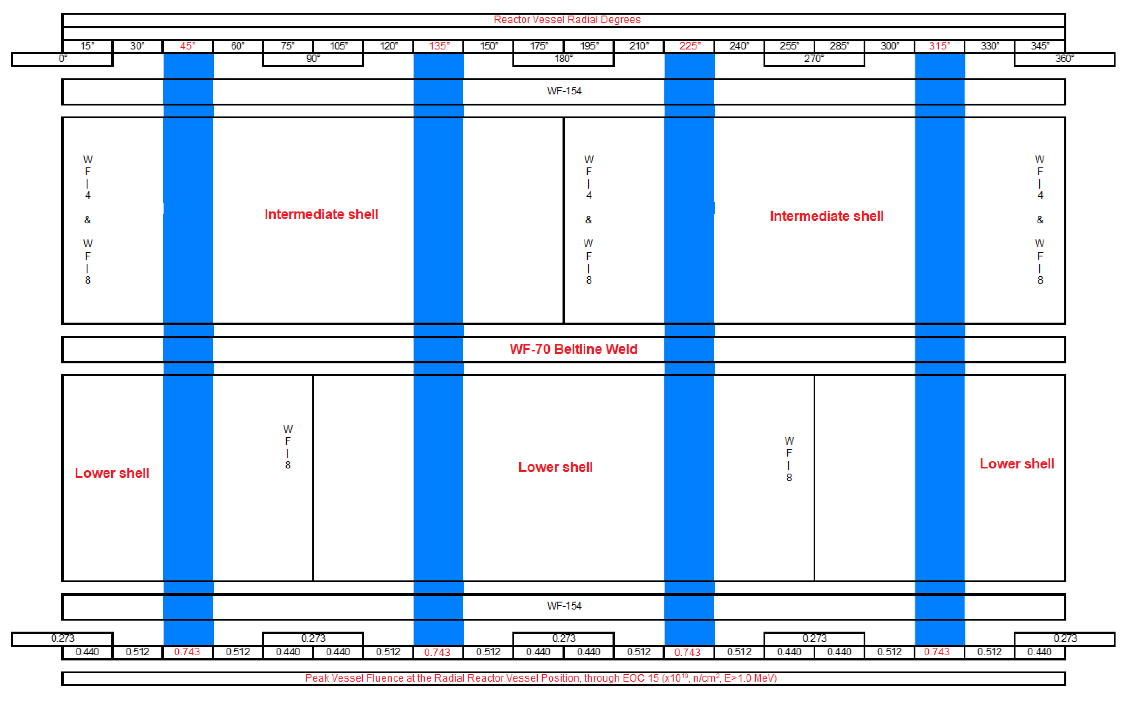
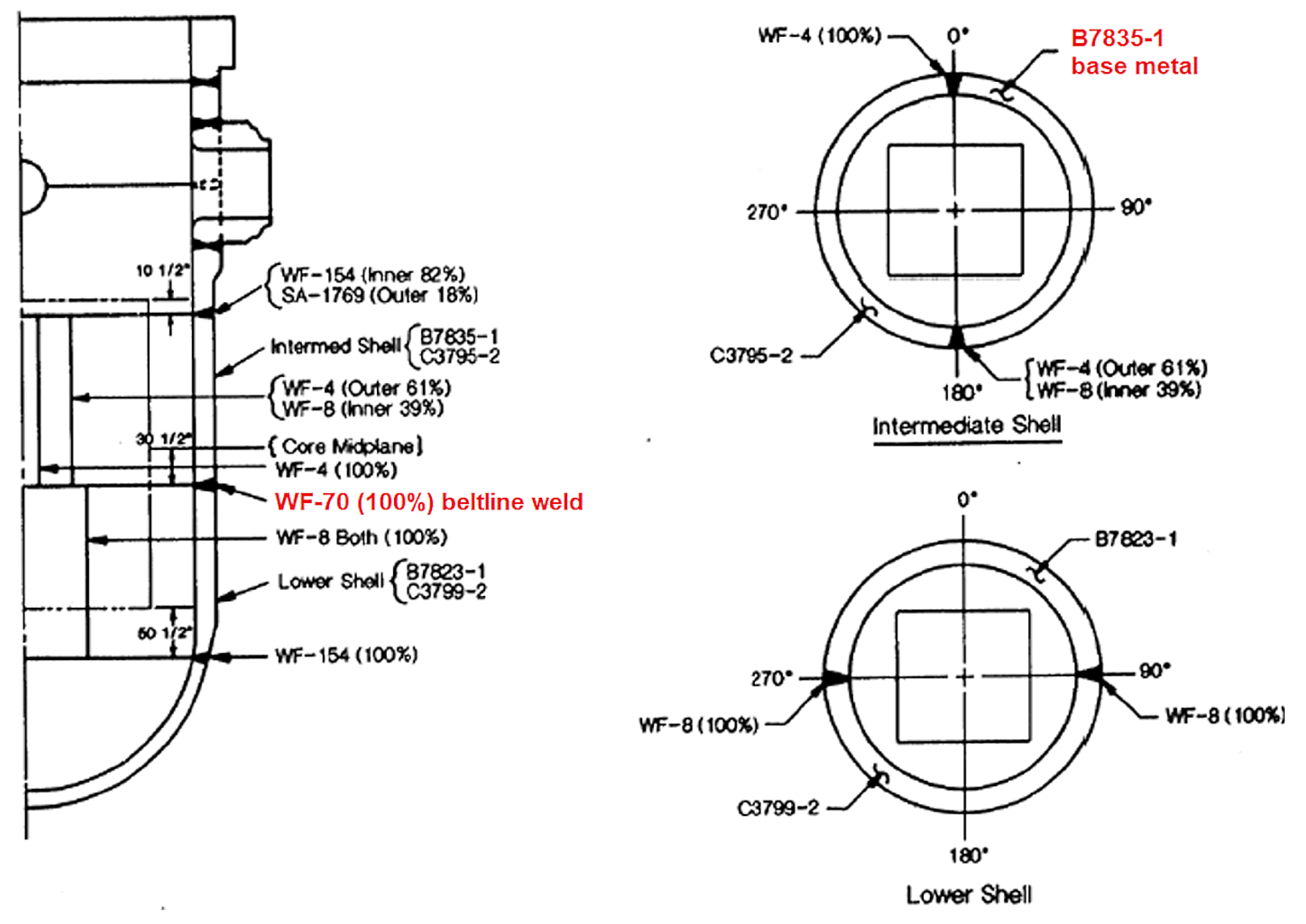
2. Zion Unit 1 RPV
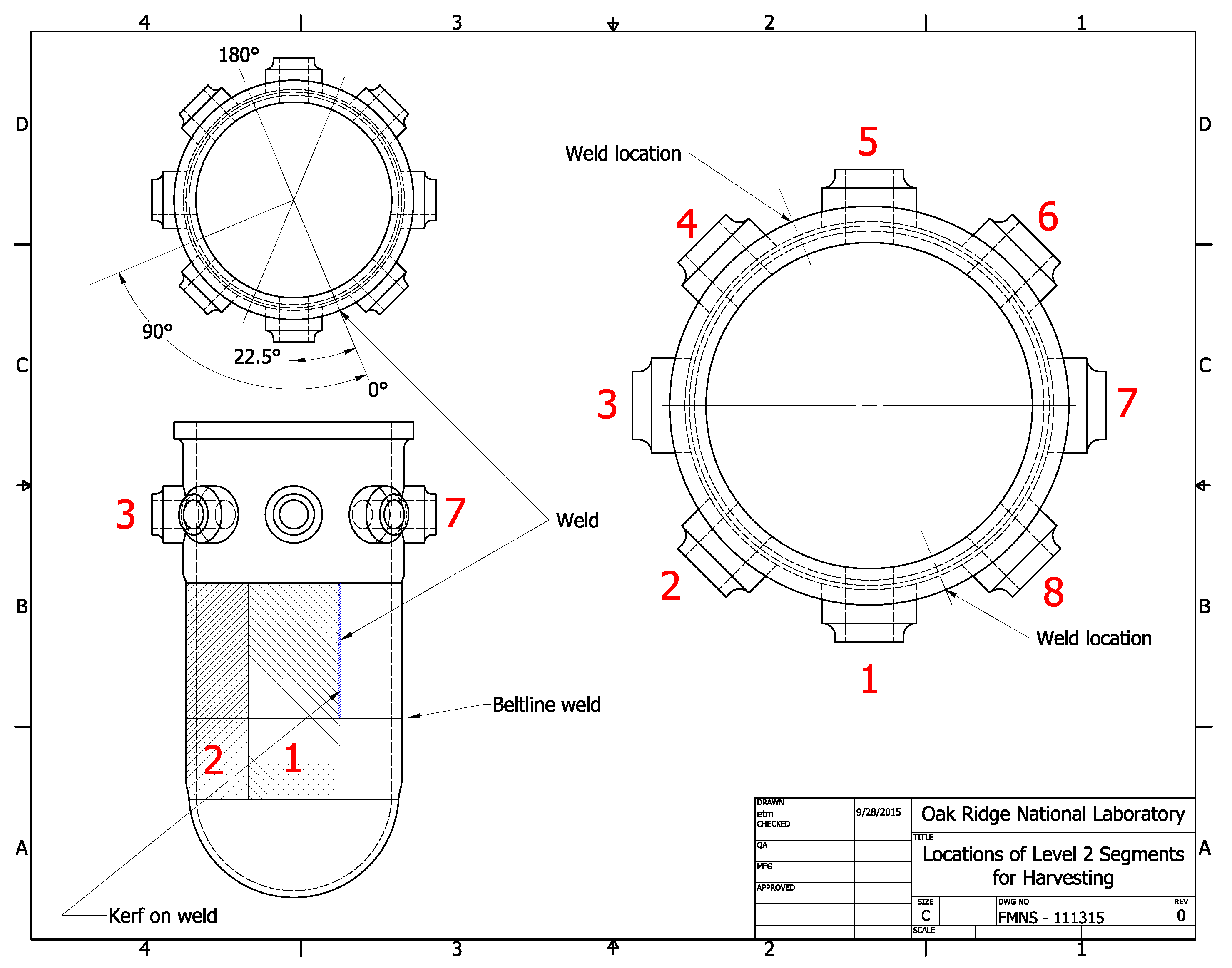
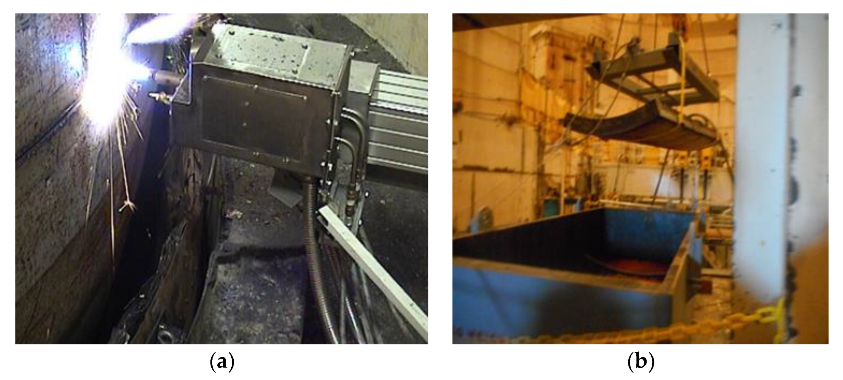
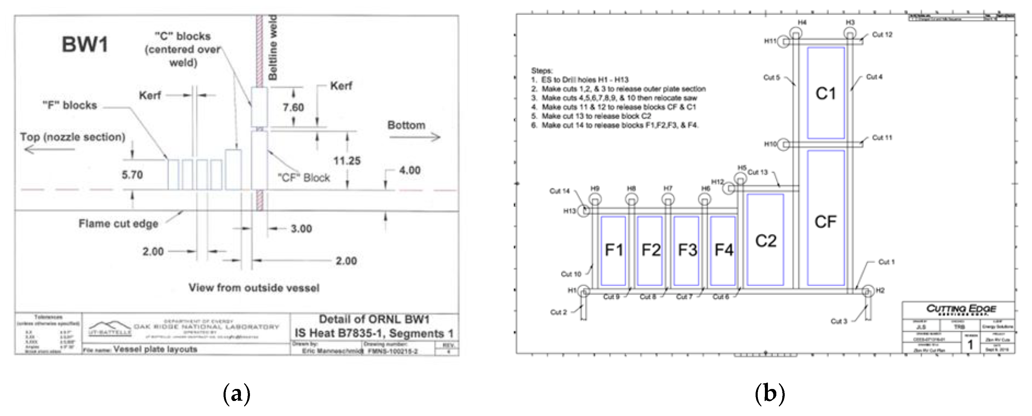
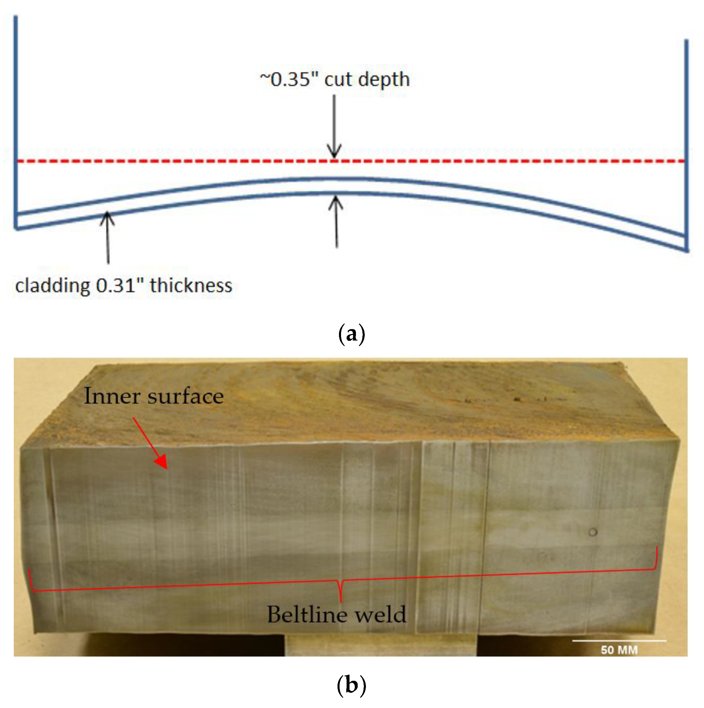
3. Segmentation
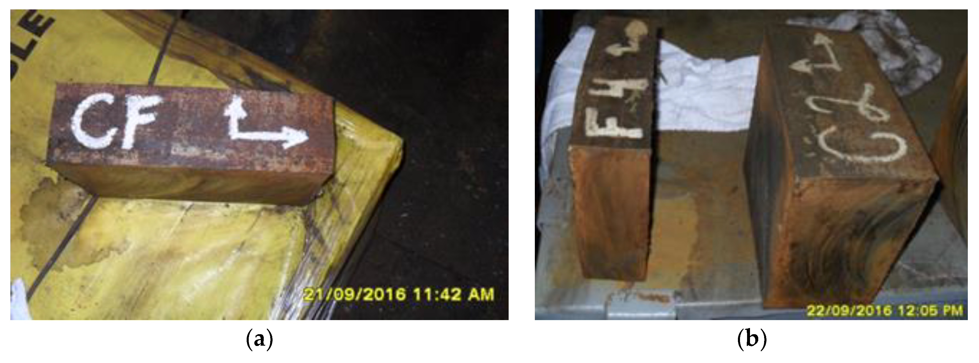
4. Harvesting
5. Cutting Sample Blocks from Segment 1
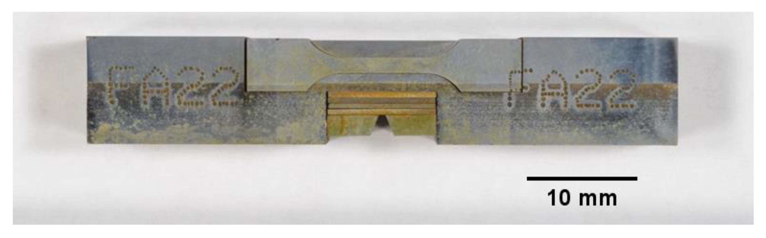
6. Machining Samples from Segment 1 Blocks
7. Chemical Composition
8. Summary
Author Contributions
Funding
Data Availability Statement
Acknowledgments
Conflicts of Interest
References
- Rosseel, T.M.; Sokolov, M.; Nanstad, R.K. Machining Test Specimens from Harvested Zion RPV Segments. In Proceedings of the ASME 2015 Pressure Vessels and Piping Conference, Boston, MA, USA, 19–23 July 2015. PVP2015-45237. [Google Scholar] [CrossRef]
- Code of Federal Regulations, 10 CFR §50.61a. Alternate Fracture Toughness Requirements for Protection Against Pressurized Thermal Shock Events; US Nuclear Regulatory Commission: Washington, DC, USA, 2010.
- ASTM E900-21; Standard Guide for Predicting Radiation-Induced Transition Temperature Shift in Reactor Vessel Materials. ASTM International: West Conshohocken, PA, USA, 2021.
- Radiation Embrittlement of Reactor Vessel Materials. Regulatory Guide 1.99, Revision 2, U.S. Nuclear Regulatory Commission; U.S. National Technical Information Service: Springfield, VA, USA, 1988.
- Eason, E.D.; Wright, J.E.; Odette, G.R. Improved Embrittlement Correlations for Reactor Pressure Vessel Steels; NUREG/CR-6551; U.S. Nuclear Regulatory Commission: Washington, DC, USA, 1998. [Google Scholar]
- Kirk, M.; Santos, C.; Eason, E.D.; Wright, J.E.; Odette, G.R. Updated embrittlement trend curve for reactor pressure vessel steels, Paper G01-5. In Proceedings of the Transactions of the 17th International Conference on Structural Mechanics in Reactor Technology (SMiRT 17), Prague, Czech Republic, 17–22 August 2003; pp. 1–8. [Google Scholar]
- Server, W.; English, C.; Naiman, D.; Rosinski, S. Charpy Embrittlement Correlations—Status of Combined Mechanistic and Statistical Bases for U.S. RPV Steels (MRP-45); Report 1000705; EPRI: Palo Alto, CA, USA, 2001. [Google Scholar]
- Busby, J.T. Light Water Reactor Sustainability Program, Materials Aging and Degradation Pathway Technical Program Plan, ORNL/LTR-2012/327, Rev. 1; Oak Ridge National Laboratory: Oak Ridge, TN, USA, 2012. [Google Scholar]
- Kussmaul, K.; Föhl, J.; Weissenberg, T. Investigation of Materials from a Decommissioned Reactor Pressure Vessel—A Contribution to the Understanding of Irradiation Embrittlement. In Effects of Radiation on Materials: 14th International Symposium (Volume II), ASTM STP 1046; Packan, N.H., Stoller, R.E., Kumar, A.S., Eds.; ASTM International: West Conshohocken, PA, USA, 1990; pp. 80–104. [Google Scholar]
- Brillaud, C.; Grandjean, Y.; Saillet, S. Vessel Investigation Program of “CHOOZ A” PWR Reactor after Shutdown. In Effects of Radiation on Materials: 20th International Symposium, ASTM 1405; Rosinski, S.T., Grossbeck, M.L., Allen, T.R., Kumar, A.S., Eds.; ASTM: West Conshohocken, PA, USA, 2001. [Google Scholar]
- Valo, M.J.; Amaev, A.D.; Ahlstrand, R.; Christiakov, D.A.; Krasikov, E.; Kryukov, A.; Morosov, A.M.; Nikoloaev, V.A.; Platonov, P.; Rintamaa, R.; et al. Characterization of the Decommissioned Novoronesh-1 Pressure Vessel Wall Material by Through Wall Trepans. In Effects of Radiation on Materials: 19th International Symposium, ASTM STP 1366; ASTM: West Conshohocken, PA, USA, 2000; pp. 98–117. [Google Scholar]
- Viehrig, H.-W.; Schuhknecht, J.; Rindelhardt, U.; Weis, F.-P. Investigation of Beltline Welding Seam of the Greifswald WWER-440 Unit 1 Reactor Pressure Vessel. J. ASTM Int. 2009, 6, 115–128. [Google Scholar] [CrossRef]
- ASTM E1921-08; Standard Test Method for Determination of Reference Temperature, T0, for Ferritic Steels in the Transition Range. ASTM International: West Conshohocken, PA, USA, 2008.
- Lindqvist, S.; Norrgård, A.; Arffman, P.; Hytonen, A.; Lydman, J.; Efsing, P.; Suman, S.; Nevasmaa, P. Mechanical behavior of high-Ni/high-Mn Barsebäck 2 reactor pressure vessel welds after 28 years of operation. J. Nucl. Mater. 2023, 581, 154447. [Google Scholar] [CrossRef]
- Yoon, K.K.; Hall, J.B. Initial RTNDT of Linde 80 Weld Materials. AREVA Document BAW-2308, Revision 0, ML022200555. July 2002. Available online: https://www.nrc.gov/docs/ML0222/ML022200555.pdf (accessed on 15 January 2025).
- Terek, E.; Anderson, S.L.; Albertin, L. Analysis of Capsule Y from the Commonwealth Edison Company Zion Unit 2 Reactor Vessel Radiation Surveillance Program; WCAP-12396; Westinghouse Electric Corporation: Pittsburgh, PA, USA, 1989. [Google Scholar]
- Yanichko, S.E.; Anderson, S.L.; Shogun, R.P.; Lott, R.G. Analysis of Capsule U from the Commonwealth Edison Company Zion Unit 1 Reactor Vessel Radiation Surveillance Program; WCAP-9890; Westinghouse Electric Corporation: Pittsburgh, PA, USA, 1981. [Google Scholar]
- Rosseel, T.M.; Sokolov, M.; Chen, X.; Nanstad, R.K. Current Status of the Characterization of RPV Materials Harvested from the Decommissioned Zion Unit 1 Nuclear Power Plant. In Proceedings of the ASME 2017 Pressure Vessels and Piping Conference, Waikoloa, HI, USA, 16–20 July 2017. PVP2017-65090. [Google Scholar] [CrossRef]
- Yanichko, S.E.; Lege, D.L. Commonwealth Edison Co. Zion Unit 2 Reactor Vessel Radiation Surveillance Program; WCAP-8132; Westinghouse Electric Corporation: Pittsburgh, PA, USA, 1973. [Google Scholar]


| Specimen Type | Total Samples |
|---|---|
| 0.5T C(T) specimen | 102 |
| Mini-C(T) | 48 |
| Charpy V-notch specimen | 239 |
| Coupons for chemical composition and microstructural characterization | 90 |
| SS3 tensile specimen | 128 |
| Specimen Type | Total Samples |
|---|---|
| Charpy V-notch Specimen | 174 |
| Coupons for chemical composition and microstructural characterization | 72 |
| SS3 tensile specimens | 142 |
| 0.4T C(T) specimen | 77 |
| Mini-CT | 9 |
| I.D. | Chemical Composition (wt%) | ||||||
|---|---|---|---|---|---|---|---|
| Si | P | Cr | Mn | Ni | Cu | Mo | |
| 2A15 | 0.29 | 0.007 | 0.11 | 1.36 | 0.44 | 0.12 | 0.44 |
| 2B01 | 0.22 | 0.006 | 0.13 | 1.34 | 0.50 | 0.13 | 0.48 |
| 2C15 | 0.26 | 0.008 | 0.10 | 1.31 | 0.46 | 0.11 | 0.46 |
| 2D01 | 0.25 | 0.006 | 0.10 | 1.48 | 0.51 | 0.13 | 0.47 |
| 2E15 | 0.21 | 0.016 | 0.10 | 1.34 | 0.53 | 0.14 | 0.47 |
| 2F01 | 0.24 | 0.008 | 0.10 | 1.26 | 0.52 | 0.13 | 0.48 |
| 2G15 | 0.24 | 0.008 | 0.10 | 1.27 | 0.46 | 0.11 | 0.47 |
| 2H01 | 0.26 | 0.009 | 0.11 | 1.52 | 0.54 | 0.14 | 0.51 |
| 2I15 | 0.22 | 0.006 | 0.09 | 1.28 | 0.49 | 0.12 | 0.47 |
| 2J01 | 0.24 | 0.009 | 0.09 | 1.32 | 0.48 | 0.11 | 0.46 |
| 2K15 | 0.30 | 0.010 | 0.12 | 1.39 | 0.58 | 0.16 | 0.53 |
| 2L01 | 0.25 | 0.008 | 0.12 | 1.42 | 0.56 | 0.15 | 0.58 |
| 2M15 | 0.29 | 0.010 | 0.10 | 1.41 | 0.51 | 0.12 | 0.51 |
| 2N01 | 0.30 | 0.012 | 0.13 | 1.31 | 0.50 | 0.13 | 0.44 |
| 2O15 | 0.21 | 0.006 | 0.09 | 1.46 | 0.50 | 0.12 | 0.46 |
| 2P01 | 0.25 | 0.009 | 0.10 | 1.34 | 0.51 | 0.12 | 0.54 |
| 2Q15 | 0.20 | 0.006 | 0.13 | 1.38 | 0.52 | 0.13 | 0.47 |
| CVN I.D. | Chemical Composition (wt%) | ||||||
|---|---|---|---|---|---|---|---|
| Si | P | Cr | Mn | Ni | Cu | Mo | |
| FA03 | 0.66 | 0.017 | 0.10 | 1.59 | 0.58 | 0.37 | 0.41 |
| FA22 | 0.68 | 0.018 | 0.10 | 1.42 | 0.55 | 0.34 | 0.43 |
| FC01 | 0.59 | 0.016 | 0.08 | 1.35 | 0.53 | 0.34 | 0.34 |
| FC22 | 0.64 | 0.016 | 0.09 | 1.59 | 0.58 | 0.37 | 0.38 |
| FE01 | 0.66 | 0.018 | 0.08 | 1.49 | 0.57 | 0.34 | 0.37 |
| FE22 | 0.58 | 0.015 | 0.07 | 1.47 | 0.48 | 0.27 | 0.34 |
| FG01 | 0.63 | 0.016 | 0.08 | 1.43 | 0.50 | 0.33 | 0.33 |
| FG22 | 0.57 | 0.019 | 0.07 | 1.51 | 0.54 | 0.32 | 0.35 |
| FI01 | 0.58 | 0.017 | 0.06 | 1.57 | 0.51 | 0.28 | 0.34 |
| FI22 | 0.68 | 0.017 | 0.10 | 1.62 | 0.54 | 0.32 | 0.39 |
| FK01 | 0.68 | 0.019 | 0.10 | 1.49 | 0.54 | 0.35 | 0.39 |
| FK22 | 0.69 | 0.020 | 0.09 | 1.66 | 0.55 | 0.33 | 0.39 |
| FM01 | 0.63 | 0.019 | 0.06 | 1.65 | 0.57 | 0.37 | 0.38 |
| FM22 | 0.67 | 0.020 | 0.06 | 1.66 | 0.59 | 0.35 | 0.38 |
| FO01 | 0.70 | 0.015 | 0.10 | 1.34 | 0.52 | 0.36 | 0.38 |
| FO22 | 0.61 | 0.017 | 0.07 | 1.47 | 0.51 | 0.35 | 0.37 |
| FQ01 | 0.71 | 0.020 | 0.09 | 1.60 | 0.60 | 0.29 | 0.42 |
| FQ22 | 0.59 | 0.018 | 0.06 | 1.47 | 0.55 | 0.27 | 0.32 |
Disclaimer/Publisher’s Note: The statements, opinions and data contained in all publications are solely those of the individual author(s) and contributor(s) and not of MDPI and/or the editor(s). MDPI and/or the editor(s) disclaim responsibility for any injury to people or property resulting from any ideas, methods, instructions or products referred to in the content. |
© 2025 by the authors. Licensee MDPI, Basel, Switzerland. This article is an open access article distributed under the terms and conditions of the Creative Commons Attribution (CC BY) license (https://creativecommons.org/licenses/by/4.0/).
Share and Cite
Rosseel, T.M.; Sokolov, M.A.; Chen, X.; Nanstad, R.K. Harvesting Reactor Pressure Vessel Beltline Material from the Decommissioned Zion Nuclear Power Plant Unit 1. Metals 2025, 15, 634. https://doi.org/10.3390/met15060634
Rosseel TM, Sokolov MA, Chen X, Nanstad RK. Harvesting Reactor Pressure Vessel Beltline Material from the Decommissioned Zion Nuclear Power Plant Unit 1. Metals. 2025; 15(6):634. https://doi.org/10.3390/met15060634
Chicago/Turabian StyleRosseel, Thomas M., Mikhail A. Sokolov, Xiang (Frank) Chen, and Randy K. Nanstad. 2025. "Harvesting Reactor Pressure Vessel Beltline Material from the Decommissioned Zion Nuclear Power Plant Unit 1" Metals 15, no. 6: 634. https://doi.org/10.3390/met15060634
APA StyleRosseel, T. M., Sokolov, M. A., Chen, X., & Nanstad, R. K. (2025). Harvesting Reactor Pressure Vessel Beltline Material from the Decommissioned Zion Nuclear Power Plant Unit 1. Metals, 15(6), 634. https://doi.org/10.3390/met15060634