Continuous Fabrication Process of Aluminum Foam from Foaming to Press Forming


Abstract
1. Introduction
2. Materials and Methods
2.1. Precursor Fabrication Method
2.2. Precursor Foaming and Press-Forming Method
2.3. Evaluation Method
3. Results and Discussion
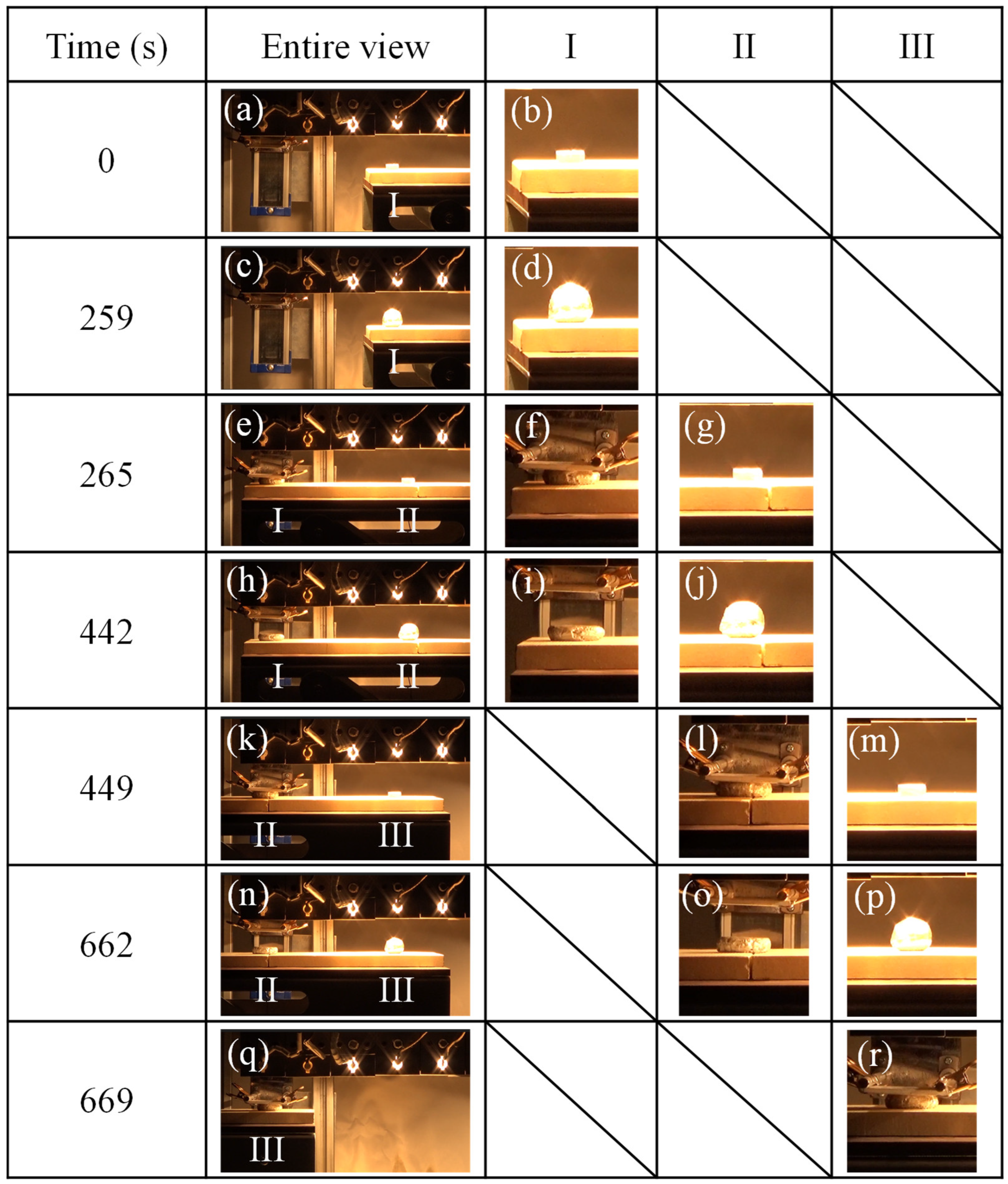
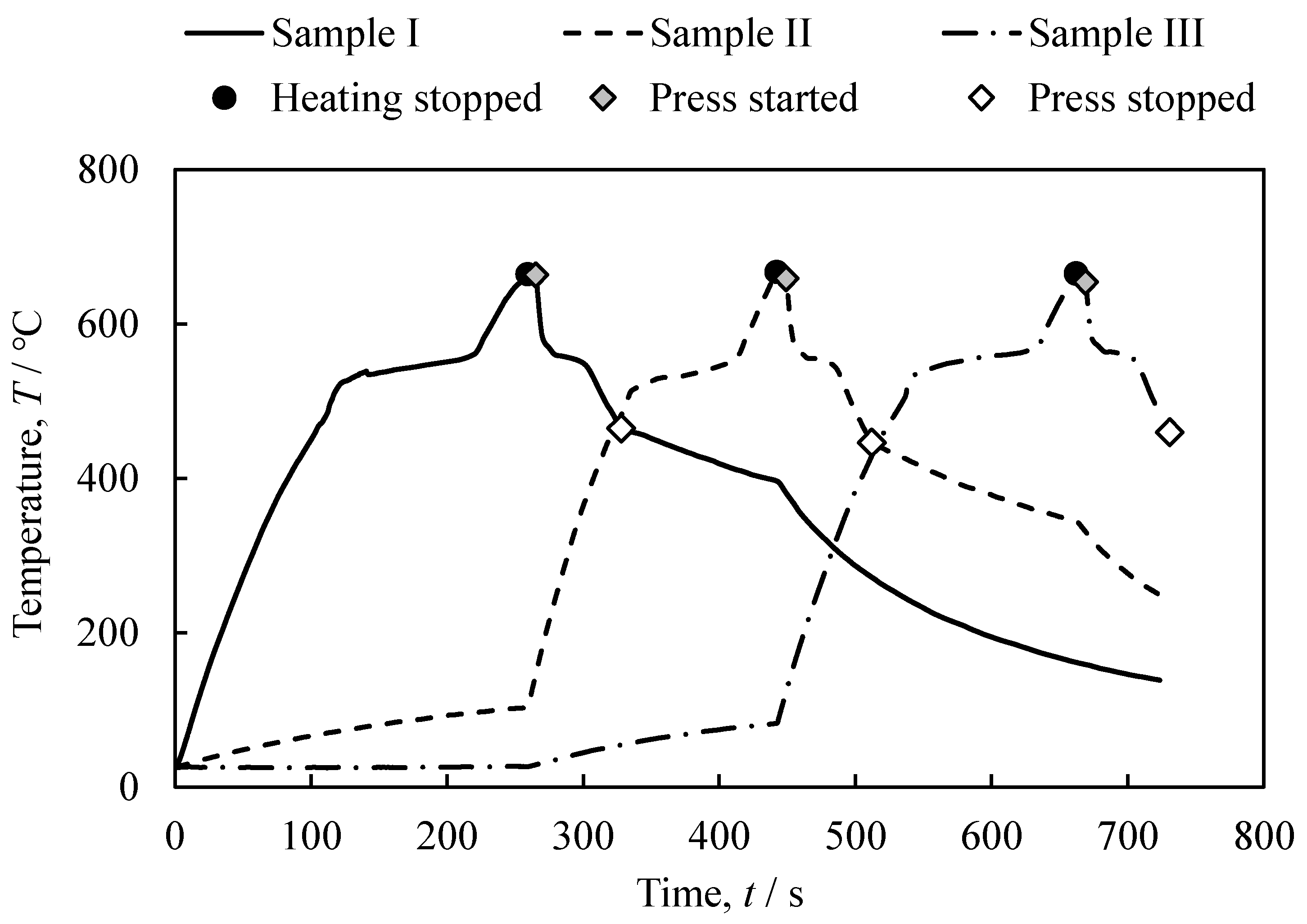
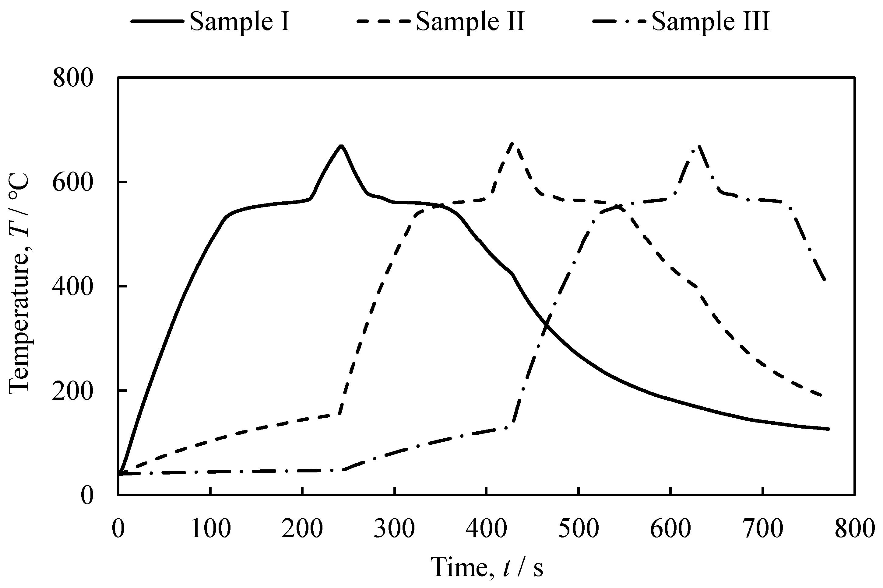
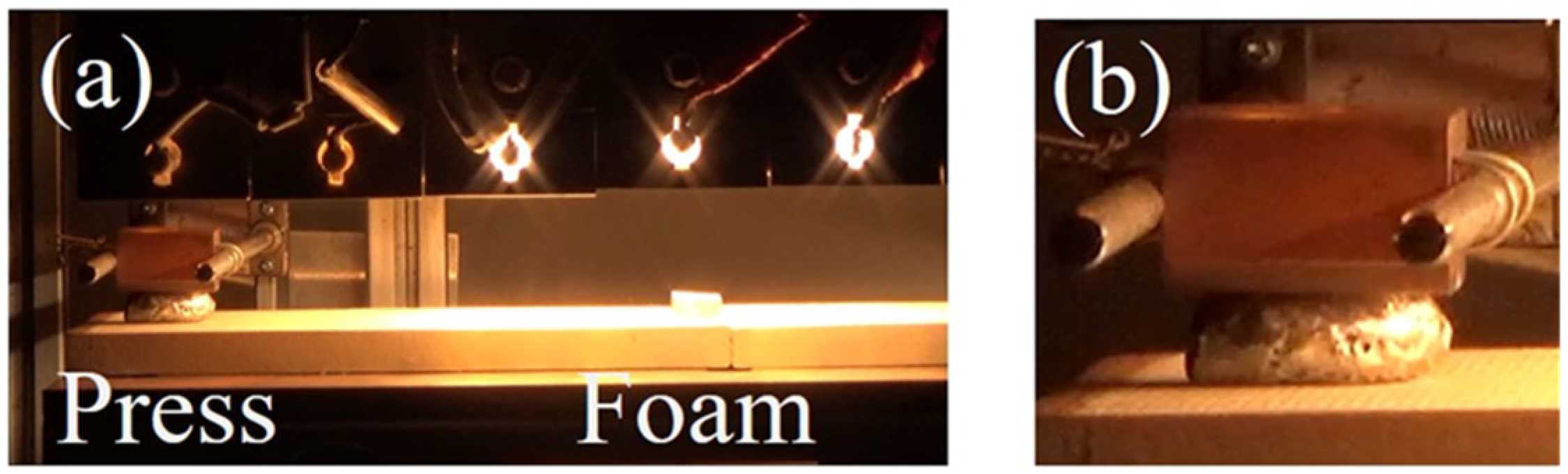
3.1. The Foaming and Press-Forming Processes
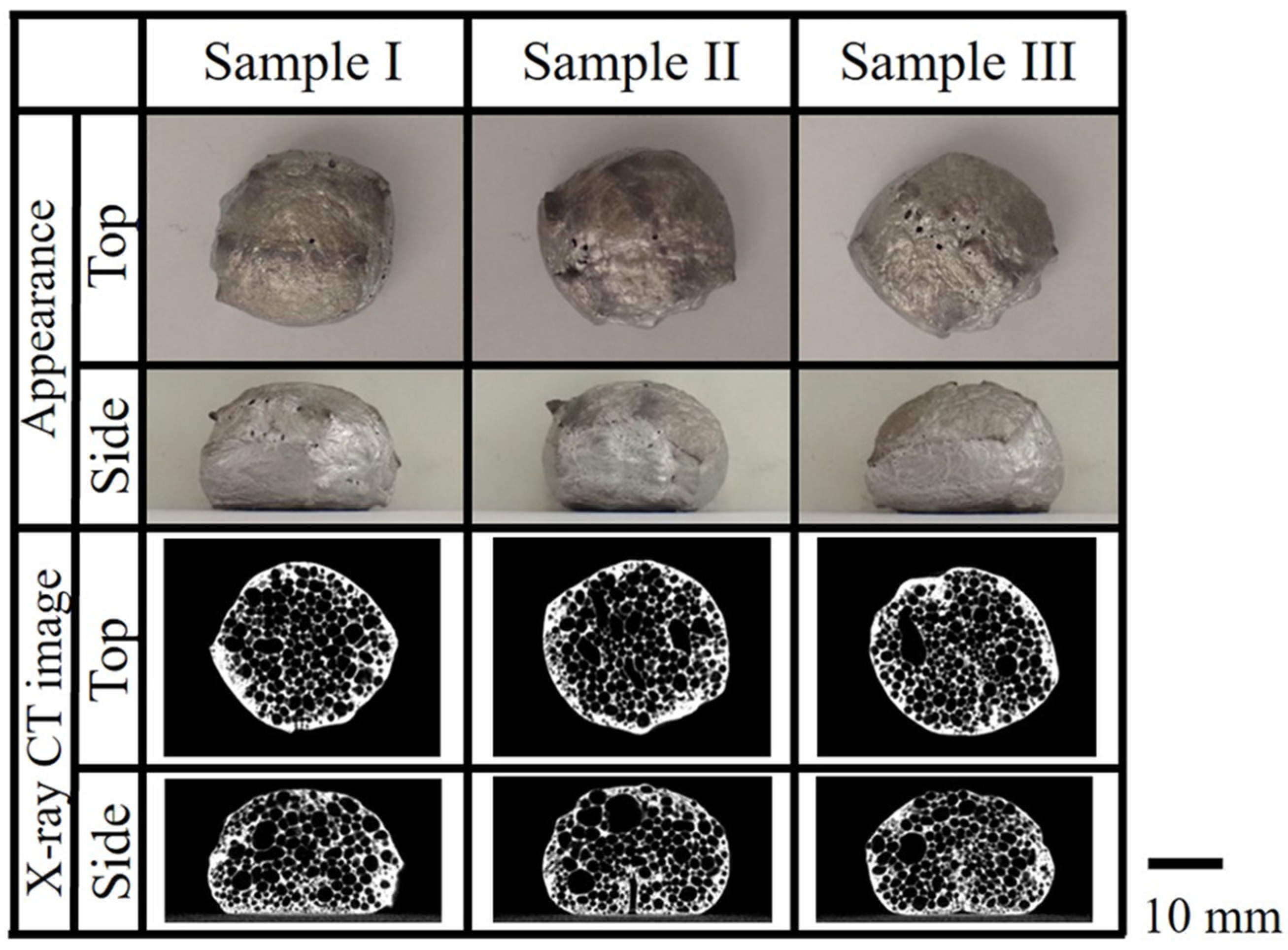
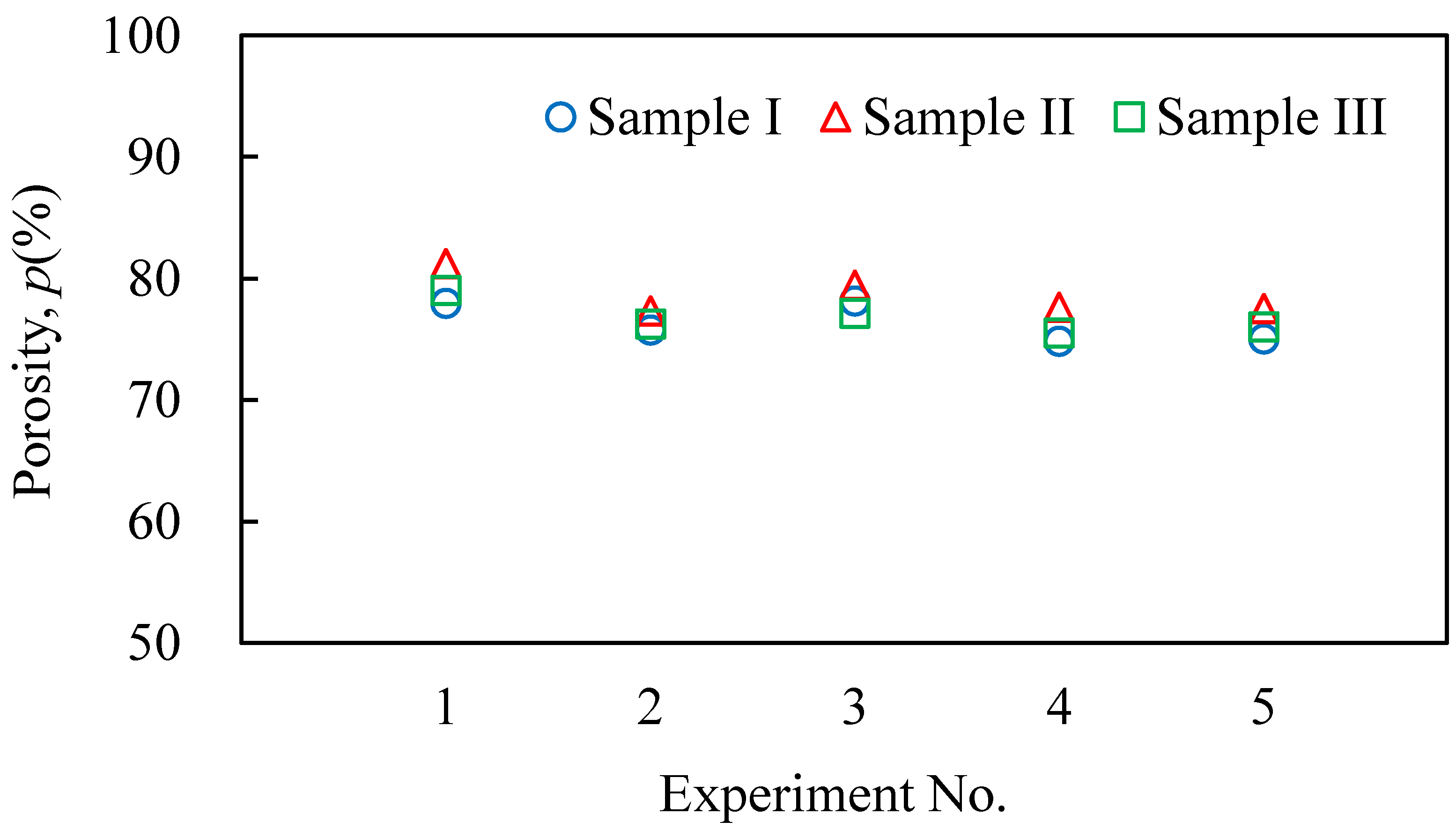
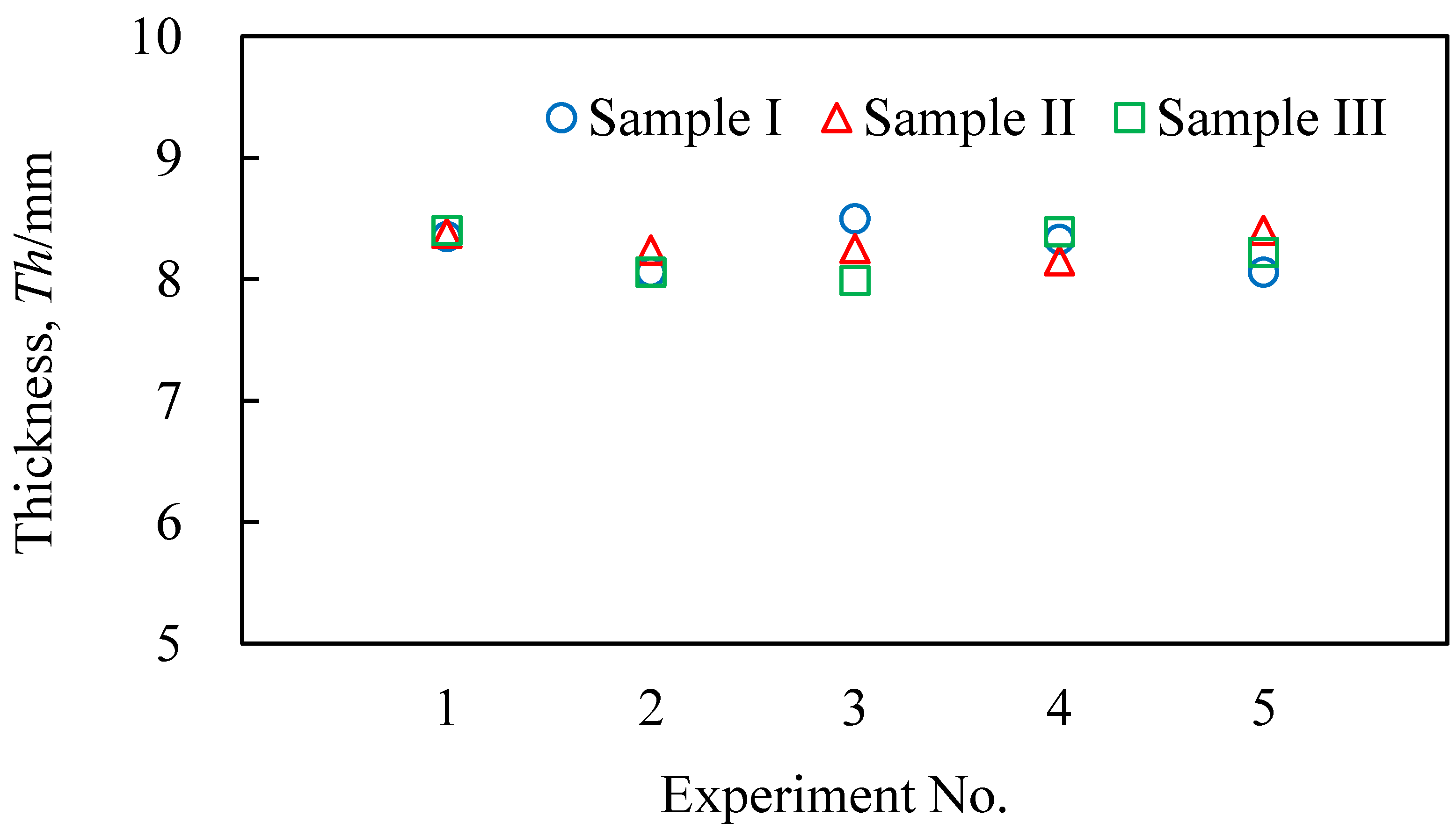
3.2. Evaluation Results of the Obtained Aluminum Foam
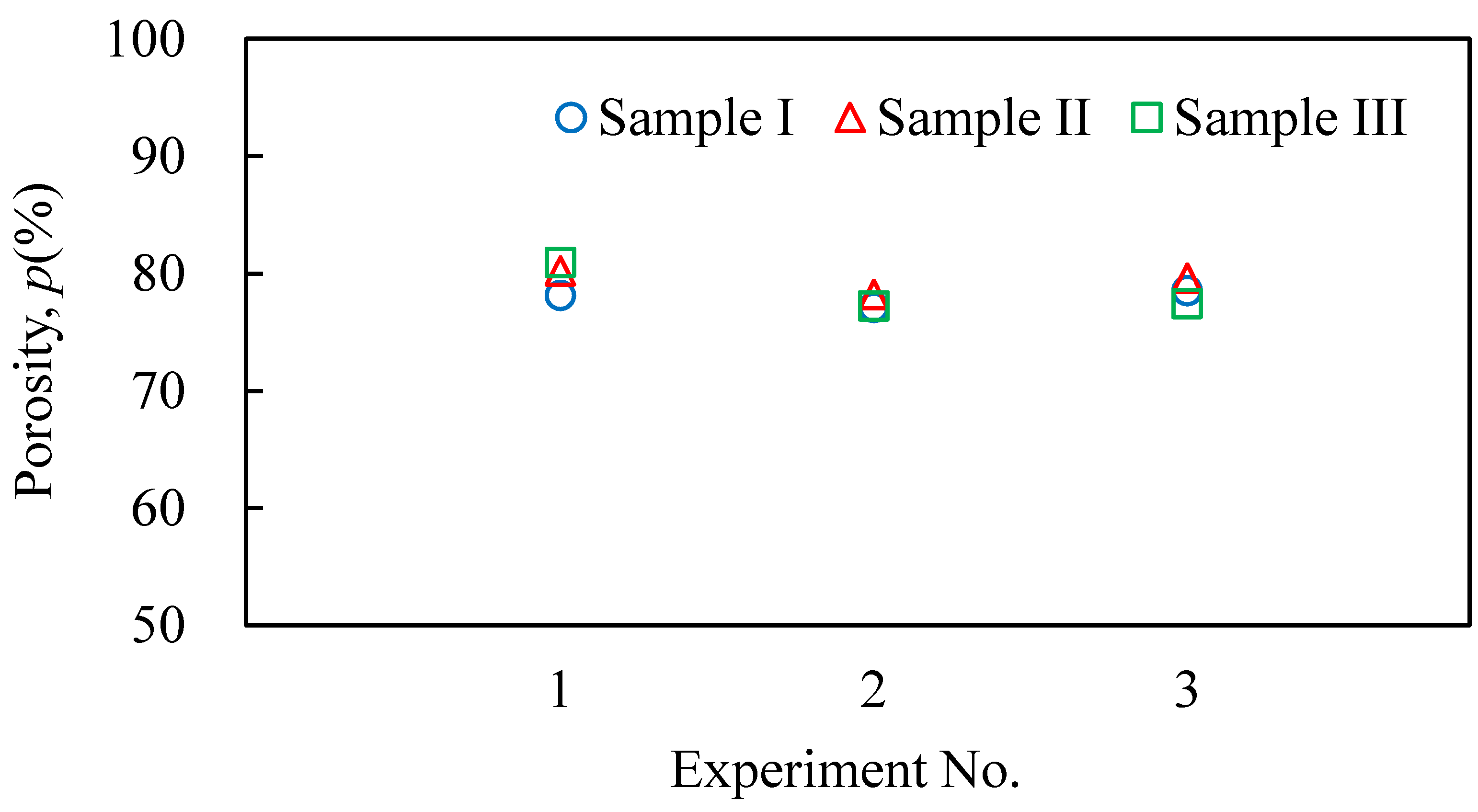
3.3. Application to Aluminum Foam with a Wave Shape
4. Conclusions
- (1)
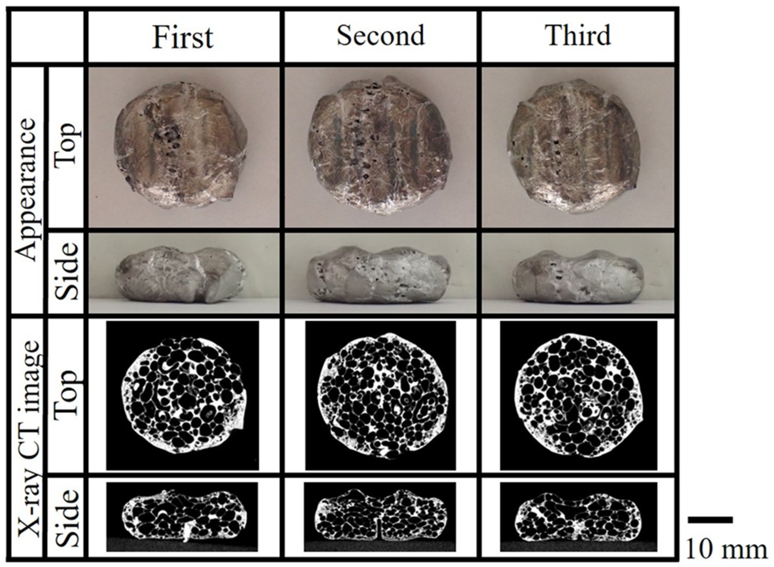
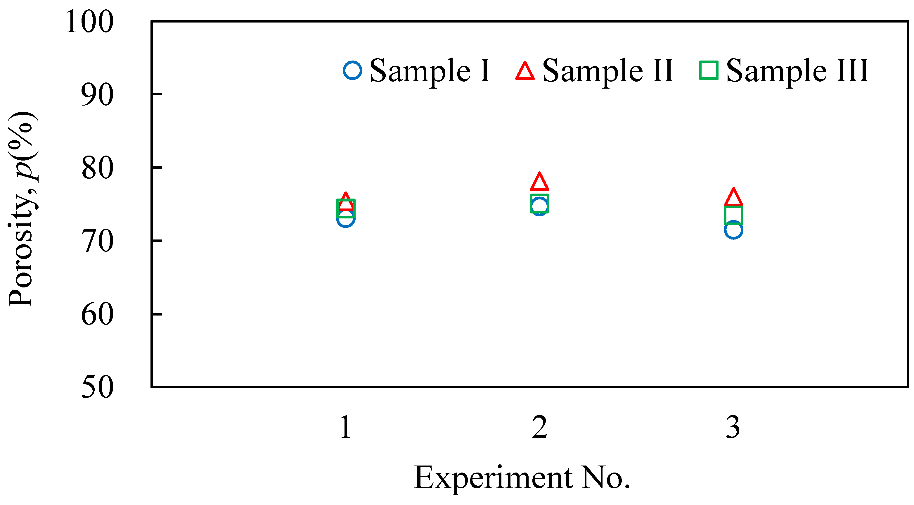
- It was shown that it is possible to continuously and sequentially foam the precursors by heating and press forming the foamed samples. The continuously obtained aluminum foam samples had a similar shape, porosity, and pore structure.
- (2)
- The continuously press-formed aluminum foam samples had a similar shape, porosity, and pore structure to those of free-foamed aluminum foam.
- (3)
- It was shown that aluminum foam with complex shapes can also be continuously fabricated by using a complex-shaped die.
- (4)
- It was indicated that the use of dies in press forming can shorten the cooling time and reduce the production time approximately from 1/2 to 1/3.
- (5)
- It will be essential to further investigate the heating and foaming methods to obtain a uniform pore structure in the future.
Author Contributions
Funding
Data Availability Statement
Conflicts of Interest
References
- Banhart, J. Light-Metal Foams—History of Innovation and Technological Challenges. Adv. Eng. Mater. 2013, 15, 82–111. [Google Scholar] [CrossRef]
- García-Moreno, F. Commercial applications of metal foams: Their properties and production. Materials 2016, 9, 85. [Google Scholar] [CrossRef] [PubMed]
- Wan, T.; Liu, Y.; Zhou, C.; Chen, X.; Li, Y. Fabrication, properties, and applications of open-cell aluminum foams: A review. J. Mater. Sci. Technol. 2021, 62, 11–24. [Google Scholar] [CrossRef]
- Ji, C.; Huang, H.; Wang, T.; Huang, Q. Recent advances and future trends in processing methods and characterization technologies of aluminum foam composite structures: A review. J. Manuf. Process. 2023, 93, 116–152. [Google Scholar] [CrossRef]
- Chen, D.; Gao, K.; Yang, J.; Zhang, L. Functionally graded porous structures: Analyses, performances, and applications—A Review. Thin-Walled Struct. 2023, 191, 111046. [Google Scholar] [CrossRef]
- Fu, W.; Li, Y. Fabrication, Processing, Properties, and Applications of Closed-Cell Aluminum Foams: A Review. Materials 2024, 17, 560. [Google Scholar] [CrossRef]
- Kathuria, Y.P. A preliminary study on laser assisted aluminum foaming. J. Mater. Sci. 2003, 38, 2875–2881. [Google Scholar] [CrossRef]
- Guglielmotti, A.; Quadrini, F.; Squeo, E.A.; Tagliaferri, V. Laser bending of aluminum foam sandwich panels. Adv. Eng. Mater. 2009, 11, 902–906. [Google Scholar] [CrossRef]
- Quadrini, F.; Guglielmotti, A.; Squeo, E.A.; Tagliaferri, V. Laser forming of open-cell aluminium foams. J. Mater. Process. Technol. 2010, 210, 1517–1522. [Google Scholar] [CrossRef]
- Yilbas, B.S.; Akhtar, S.S.; Keles, O. Laser hole cutting in aluminum foam: Influence of hole diameter on thermal stress. Opt. Lasers Eng. 2013, 51, 23–29. [Google Scholar] [CrossRef]
- Changdar, A.; Chakraborty, S.S. Laser processing of metal foam—A review. J. Manuf. Process. 2021, 61, 208–225. [Google Scholar] [CrossRef]
- Jackson, K.P.; Allwood, J.M.; Landert, M. Incremental forming of sandwich panels. J. Mater. Process. Technol. 2008, 204, 290–303. [Google Scholar] [CrossRef]
- Matsumoto, R.; Tsuruoka, H.; Otsu, M.; Utsunomiya, H. Fabrication of skin layer on aluminum foam surface by friction stir incremental forming and its mechanical properties. J. Mater. Process. Technol. 2015, 218, 23–31. [Google Scholar] [CrossRef]
- Matsumoto, R.; Mori, S.; Otsu, M.; Utsunomiya, H. Formation of skin surface layer on aluminum foam by friction stir powder incremental forming. Int. J. Adv. Manuf. Technol. 2018, 99, 1853–1861. [Google Scholar] [CrossRef]
- Contorno, D.; Filice, L.; Fratini, L.; Micari, F. Forming of aluminum foam sandwich panels: Numerical simulations and experimental tests. J. Mater. Process. Technol. 2006, 177, 364–367. [Google Scholar] [CrossRef]
- Banhart, J.; Seeliger, H.W. Aluminium Foam Sandwich Panels: Manufacture, Metallurgy and Applications. Adv. Eng. Mater. 2008, 10, 793–802. [Google Scholar] [CrossRef]
- Gagliardi, F.; Filice, L.; Umbrello, D.; Shivpuri, R. Forging of metallic foams to reproduce biomechanical components. Mater. Sci. Eng. A 2008, 480, 510–516. [Google Scholar] [CrossRef]
- Cai, Z.-Y.; Zhang, X.; Liang, X.-B. Multi-point forming of sandwich panels with egg-box-like cores and failure behaviors in forming process: Analytical models, numerical and experimental investigations. Mater. Des. 2018, 160, 1029–1041. [Google Scholar] [CrossRef]
- Zhang, W.; Cai, Z.; Zhang, X.; Gao, J.; Wang, M.; Chen, Q. Numerical Simulation Analysis on Surface Quality of Aluminum Foam Sandwich Panel in Plastic Forming. Metals 2023, 13, 65. [Google Scholar] [CrossRef]
- Kim, W.Y.; Kim, W.J.; Utsunomiya, H. Accelerated Formation of an Ultrafine-Grained Microstructure in Closed-Cell Aluminum Foam after Extrusion and Differential Speed Rolling. Mater. Trans. 2017, 58, 291–293. [Google Scholar] [CrossRef]
- Weiss, M.; Abeyrathna, B.; Pereira, M. Roll formability of aluminium foam sandwich panels. Int. J. Adv. Manuf. Technol. 2018, 97, 953–965. [Google Scholar] [CrossRef]
- Neu, T.R.; Heim, K.; Seeliger, W.; Kamm, P.H.; García-Moreno, F. Aluminum Foam Sandwiches: A Lighter Future for Car Bodies. JOM 2024, 76, 2619–2630. [Google Scholar] [CrossRef]
- Nassar, H.; Albakri, M.; Pan, H.; Khraisheh, M. On the gas pressure forming of aluminium foam sandwich panels: Experiments and numerical simulations. CIRP Ann. 2012, 61, 243–246. [Google Scholar] [CrossRef]
- Mata, H.; Santos, A.D.; Parente, M.P.L.; Valente, R.A.F.; Fernandes, A.A.; Jorge, R.N. Study on the forming of sandwich shells with closed-cell foam cores. Int. J. Mater. Form. 2014, 7, 413–424. [Google Scholar] [CrossRef]
- Liu, Z.-y.; Cheng, Y.; Li, Y.-x.; Zhou, X.; Chen, X.; Wang, N.-z. Shape formation of closed-cell aluminum foam in solid–liquid–gas coexisting state. Int. J. Miner. Metall. Mater. 2018, 25, 974–980. [Google Scholar] [CrossRef]
- Liu, Z.; Cheng, Y.; Li, Y.; Wang, N.; Zhou, X. Study on Deformation of Closed-Cell Aluminum Foam in Different Solid–Liquid–Gas Coexisting State. Met. Mater. Int. 2021, 27, 403–412. [Google Scholar] [CrossRef]
- Baumgartner, F.; Duarte, I.; Banhart, J. Industrialization of powder compact foaming process. Adv. Eng. Mater. 2000, 2, 168–174. [Google Scholar] [CrossRef]
- Durante, M.; Formisano, A.; Viscusi, A.; Carrino, L. An innovative manufacturing method of aluminum foam sandwiches using a mesh-grid reinforcement as mold. Int. J. Adv. Manuf. Technol. 2020, 107, 3039–3048. [Google Scholar] [CrossRef]
- Yang, S.; Luo, H.; Lu, X.; Wang, L.; Wang, C. Influence of Rolling on Foamable Precursor Sandwich and Aluminum Foam Sandwich. J. Mater. Eng. Perform. 2023, 32, 2488–2500. [Google Scholar] [CrossRef]
- Kobashi, M.; Sato, R.; Kanetake, N. Foaming and Filling-in Behavior of Porous Aluminum in Hollow Components. Mater. Trans. 2006, 47, 2178–2182. [Google Scholar] [CrossRef]
- Duarte, I.; Vesenjak, M.; Vide, M.J. Automated Continuous Production Line of Parts Made of Metallic Foams. Metals 2019, 9, 531. [Google Scholar] [CrossRef]
- Patel, N.; Mittal, G.; Agrawal, M.; Pradhan, A.K. Aluminum foam production, properties, and applications: A review. Int. J. Met. 2024, 18, 2181–2198. [Google Scholar] [CrossRef]
- Hangai, Y.; Kawato, D.; Ando, M.; Ohashi, M.; Morisada, Y.; Ogura, T.; Fujii, H.; Nagahiro, R.; Amagai, K.; Utsunomiya, T.; et al. Nondestructive observation of pores during press forming of aluminum foam by X-ray radiography. Mater. Charact. 2020, 170, 110631. [Google Scholar] [CrossRef]
- Hangai, Y.; Suzuki, K.; Ohashi, M.; Mitsugi, H.; Amagai, K. Roll forming of aluminum foam immediately after precursor foaming. Results Eng. 2021, 10, 100224. [Google Scholar] [CrossRef]
- Hangai, Y.; Sakaguchi, Y.; Okada, K.; Tanaka, Y. Press-forming of aluminum foam and estimation of its mechanical properties from X-ray CT images using machine learning. Mater. Charact. 2025, 221, 114781. [Google Scholar] [CrossRef]
- Duarte, I.; Banhart, J. A study of aluminium foam formation—Kinetics and microstructure. Acta Mater. 2000, 48, 2349–2362. [Google Scholar] [CrossRef]
- Hangai, Y.; Takada, K.; Fujii, H.; Aoki, Y.; Aihara, Y.; Nagahiro, R.; Amagai, K.; Utsunomiya, T.; Yoshikawa, N. Foaming of A1050 aluminum precursor by generated frictional heat during friction stir processing of steel plate. Int. J. Adv. Manuf. Technol. 2020, 106, 3131–3137. [Google Scholar] [CrossRef]
- Hangai, Y.; Utsunomiya, T.; Hasegawa, M. Effect of tool rotating rate on foaming properties of porous aluminum fabricated by using friction stir processing. J. Mater. Process. Technol. 2010, 210, 288–292. [Google Scholar] [CrossRef]
- Papantoniou, I.G.; Kyriakopoulou, H.P.; Pantelis, D.I.; Manolakos, D.E. Fabrication of MWCNT-reinforced Al composite local foams using friction stir processing route. Int. J. Adv. Manuf. Technol. 2018, 97, 675–686. [Google Scholar] [CrossRef]
- Pang, Q.; Hu, Z.L.; Song, J.S. Preparation and mechanical properties of closed-cell CNTs-reinforced Al composite foams by friction stir welding. Int. J. Adv. Manuf. Technol. 2019, 103, 3125–3136. [Google Scholar] [CrossRef]
- Shandley, R.; Maheshwari, S.; Siddiquee, A.N.; Mohammed, S.; Chen, D.L. Foaming of friction stir processed Al/MgCO3 precursor via flame heating. Mater. Res. Express 2020, 7, 026515. [Google Scholar] [CrossRef]
- Abidi, M.H.; Moiduddin, K.; Siddiquee, A.N.; Mian, S.H.; Mohammed, M.K. Development of Aluminium Metal Foams via Friction Stir Processing by Utilizing MgCO3 Precursor. Coatings 2023, 13, 162. [Google Scholar] [CrossRef]
- Pang, Q.; Zheng, J.; Hu, Z.-l. Microstructural characteristics and mechanical properties of 7075 aluminum alloy foam sandwich panels fabricated via integrated forming and foaming. J. Manuf. Process. 2023, 94, 133–145. [Google Scholar] [CrossRef]
- Papantoniou, I.G.; Manolakos, D.E. Fabrication and characterization of aluminum foam reinforced with nanostructured γ-Al2O3 via friction stir process for enhanced mechanical performance. Int. J. Adv. Manuf. Technol. 2024, 130, 5359–5368. [Google Scholar] [CrossRef]
- Zhang, Y.; Pang, Q. Study on the Process of Preparing Aluminum Foam Sandwich Panel Precursor by Friction Stir Welding. Materials 2024, 17, 4981. [Google Scholar] [CrossRef]
- Lohani, D.; Daniel, B.S.S. Quasi-static Deformation Mechanism and Compressive Properties of Aluminum Foams Fabricated by Friction Stir Processing. J. Mater. Eng. Perform. 2025, 34, 5072–5080. [Google Scholar] [CrossRef]
- JIS-H-5302; Aluminium Alloy Die Castings. Japanese Standards Association: Tokyo, Japan, 2006.
- Sato, Y.S.; Park, S.H.C.; Matsunaga, A.; Honda, A.; Kokawa, H. Novel production for highly formable Mg alloy plate. J. Mater. Sci. 2005, 40, 637–642. [Google Scholar] [CrossRef]
- Su, J.Q.; Nelson, T.W.; Sterling, C.J. Friction stir processing of large-area bulk UFG aluminum alloys. Scr. Mater. 2005, 52, 135–140. [Google Scholar] [CrossRef]
- Nakata, K.; Kim, Y.G.; Fujii, H.; Tsumura, T.; Komazaki, T. Improvement of mechanical properties of aluminum die casting alloy by multi-pass friction stir processing. Mater. Sci. Eng. A 2006, 437, 274–280. [Google Scholar] [CrossRef]
- Khan, N.A.; Chakraborty, D.; Kumar, A. Effect of Solution Heat Treatment on Corrosion Performance of Multi-pass Friction Stir Processed AA6061/Ceria-Stabilized Zirconia Composites for Marine Applications. J. Mater. Eng. Perform. 2025, in press. [Google Scholar] [CrossRef]
- Jain, S.; Mishra, R.S.; Mehdi, H. Influence of SiC Microparticles and Multi-Pass FSW on Weld Quality of the AA6082 and AA5083 Dissimilar Joints. Silicon 2023, 15, 6185–6197. [Google Scholar] [CrossRef]
- Hangai, Y.; Takahashi, K.; Yamaguchi, R.; Utsunomiya, T.; Kitahara, S.; Kuwazuru, O.; Yoshikawa, N. Nondestructive observation of pore structure deformation behavior of functionally graded aluminum foam by X-ray computed tomography. Mater. Sci. Eng. A 2012, 556, 678–684. [Google Scholar] [CrossRef]
- Hangai, Y.; Yamamoto, Y.; Goto, Y.; Okada, K.; Yoshikawa, N. Friction Welding of Polycarbonate Plate and Aluminum Foam Fabricated by Precursor Foaming Process. Metals 2023, 13, 1366. [Google Scholar] [CrossRef]
- The-Japan-Institute-of-Light-Metals. Structures and Properties of Aluminum; The Japan Institute of Light Metals: Tokyo, Japan, 1991. [Google Scholar]
- Kobashi, M.; Noguchi, M.; Kanetake, N. Observation of Foaming Behavior for Rolled Sheet Precursors Made of Various Aluminum Powders. Mater. Trans. 2011, 52, 934–938. [Google Scholar] [CrossRef]


| Si | Fe | Cu | Mn | Mg | Zn | Ni | Sn | Al | |
|---|---|---|---|---|---|---|---|---|---|
| JIS ADC12 | 9.6~12.0 | <1.3 | 1.5~3.5 | <0.5 | <0.3 | <1.0 | <0.5 | <0.2 | Bal. |
Disclaimer/Publisher’s Note: The statements, opinions and data contained in all publications are solely those of the individual author(s) and contributor(s) and not of MDPI and/or the editor(s). MDPI and/or the editor(s) disclaim responsibility for any injury to people or property resulting from any ideas, methods, instructions or products referred to in the content. |
© 2025 by the authors. Licensee MDPI, Basel, Switzerland. This article is an open access article distributed under the terms and conditions of the Creative Commons Attribution (CC BY) license (https://creativecommons.org/licenses/by/4.0/).
Share and Cite
Hangai, Y.; Kaneko, Y.; Amagai, K. Continuous Fabrication Process of Aluminum Foam from Foaming to Press Forming. Metals 2025, 15, 633. https://doi.org/10.3390/met15060633
Hangai Y, Kaneko Y, Amagai K. Continuous Fabrication Process of Aluminum Foam from Foaming to Press Forming. Metals. 2025; 15(6):633. https://doi.org/10.3390/met15060633
Chicago/Turabian StyleHangai, Yoshihiko, Yuito Kaneko, and Kenji Amagai. 2025. "Continuous Fabrication Process of Aluminum Foam from Foaming to Press Forming" Metals 15, no. 6: 633. https://doi.org/10.3390/met15060633
APA StyleHangai, Y., Kaneko, Y., & Amagai, K. (2025). Continuous Fabrication Process of Aluminum Foam from Foaming to Press Forming. Metals, 15(6), 633. https://doi.org/10.3390/met15060633