Article

Bonding Strength and Its Enhancing Mechanism of CuCr/In718 Dissimilar Materials with Mortise and Tenon Structure Interface Manufactured by Laser-Based Direct Energy Deposition (DED-LB) Using Powder Feedstock

1
School of Mechanical Engineering, Jiangsu University, Zhenjiang 212013, China
2
School of Mechanical Engineering, Jiangsu University of Science and Technology, Zhenjiang 212000, China
*
Authors to whom correspondence should be addressed.
Metals 2025, 15(5), 557; https://doi.org/10.3390/met15050557
Submission received: 31 March 2025 / Revised: 11 May 2025 / Accepted: 14 May 2025 / Published: 19 May 2025

Abstract

:
The interface bonding strength is challenging for CuCr and In718 dissimilar alloys fabricated by Laser-Based Direct Energy Deposition (DED-LB) using Powder Feedstock. Here, direct-bonded CuCr/In718 dissimilar materials (DMs) (direct-bonded specimen) and CuCr/In718 DMs with mortise and tenon structure interface (mortise-tenon specimen) were deposited by powder DED-LB. Owing to the alternating inter-track and inter-layer remelting, the defects were avoided, and the Cu elemental diffusion was obvious in the mortise-tenon specimen. Thereby, the better metallurgical bonding strength was achieved in the mortise-tenon specimen. The sandwich-shaped microstructure, including fine equiaxed and columnar grains, and the heterogeneous microstructure consisting of large columnar, short columnar, and fine equiaxed grains were formed in direct-bonded and mortise-tenon specimens, respectively. The formation mechanisms of these microstructures were unveiled, respectively. Besides, the shear strength of direct-bonded and mortise-tenon specimens was investigated. Owing to the mortise and tenon structure, the ultimate shear strength (USS) was increased by 47.18%. The synergistic enhancing mechanism of macroscopic interfacial morphology, microstructure, and elemental distribution on shear strength was revealed.

Graphical Abstract

1. Introduction

The combustion chamber liner of a rocket engine must withstand extreme thermal gradients: its inner wall faces a 5000 °C high-temperature gas flow, while the outer structural jacket requires materials that maintain superior mechanical properties at elevated temperatures [1]. Dissimilar materials with high thermal conductivity and superior mechanical properties at elevated temperatures were needed for the inner and jacket of the rocket engine combustion chamber [2]. Owing to the high thermal conductivity and electric conductivity, copper alloys are of particular interest for the inner of the rocket engine combustion chamber. Meanwhile, In718 is widely used in the jackets of rocket engine combustion chambers due to its demands for heat insulation, owing to its outstanding strength and corrosion resistance at high temperatures (650–850 °C) [3]. Hence, the joining of copper alloys and In718 is critical in rocket engine combustion chamber manufacturing.
Commonly, copper/In718 bimetal structure is connected by laser welding [4,5], friction stir welding [6], and diffusion bonding [7]. However, the combustion chamber, with its complex inner channel, restricts the applicability of these traditional techniques. Laser technology, as an innovative manufacturing method, has demonstrated its unique benefits in a variety of fields [8,9,10], including aerospace, energy, agricultural production, and other industries. Laser Additive manufacturing (AM), including Laser-Based Direct Energy Deposition (DED-LB) using Powder Feedstock, is an additive manufacturing process that employs laser energy to fuse powdered materials layer by layer. With typical deposited layer thicknesses as fine as several hundred micrometers, powder DED-LB enables high-precision, monolithic fabrication of complex geometries.
Meanwhile, powder DED-LB is a highly flexible technology, ideally suited for multi-material manufacturing, as it allows for the feeding of different powders through dual powder feeders [11,12,13]. Thanks to the excellent advantages mentioned above, powder DED-LB is a popular technology to fabricate copper/In718 combustion chambers [14]. However, the bonding interface remains its Achilles’ heel due to a significant difference in thermal conductivity and thermal expansion coefficient [15]. In practical applications, transient thermal gradient during combustion chamber operation subjects the liner and outer structural jacket to tensile or compressive stresses, respectively, generating radial loads. The nickel and copper interface between the outer structural jacket and the liner is prone to debonding failure under radially perpendicular loading [16]. Hence, enhancing the strength of the interface is important.
To date, numerous studies have focused on the interface between copper alloys and In718 (Table 1). Onuike et al. used powder DED-LB to fabricate GRCop-84 and In718 bimetal bulk [17]. The shear strength of the GRCop-84/In718 bimetal is far smaller than that of the In718 matrix. Additionally, Ryan et al. deposited Inconel alloy onto C18150 copper substrate using powder DED-LB and wire-fed DED [18]. Obvious microscopic pores and unmelted particles can be observed at the interface. In order to optimize forming quality and interfacial strength of the interface in copper alloys/In718 dissimilar materials, Zhang et al. investigated the influence of states of the CuCr0.8 substrate on the formability of In718 single track by powder DED-LB. They found that suitable thermal conductivity can improve the formability of the interface deposited by powder DED-LB [19]. Chang et al. studied the heterogeneous interfaces of copper alloys and In718 dissimilar materials deposited by different sequences, including Ni-Cu and Cu-Ni. Excellent tensile properties along the horizontal direction were obtained for Cu–Ni (Ultimate tensile strength: 573 MPa, yield stress: 302 MPa, elongation: 22%), while those of Ni–Cu are much lower due to the solidification cracks in the transition zone [15]. The above studies demonstrated that the defects and poor strength of the interface are common issues in copper and Inconel alloys, which exhibit strong process parameter dependence. The selection of reasonable parameters can ensure the formality and properties of the interface.
Nevertheless, the powder DED-LB process involved numerous parameters, and the parameter optimization required a significant amount of time. Foteinopoulos et al. proposed that simulation is one of the most widely used methods for process optimization towards improved part quality in additive manufacturing, particularly for metal parts. Additionally, they presented a new numerical approach that can be applied to any implicit numerical thermal simulation for AM, resulting in a significant decrease in computational time (over 70%) with minimal impact on accuracy [20]. Although simulation is an effective method for parameter optimization, the narrow processing window resulting from the thermophysical property differences between dissimilar alloys makes both parameter optimization and interfacial performance improvement challenging.
Apart from parameter optimization, previous research demonstrated that interface structure was an effective method in enhancing the interface bonding strength. For example, Wei et al. utilized laser remelting at the interface to enhance the shear strength of Ti6Al4V-Cu10Sn dissimilar alloys [21]. The keyhole tips were obtained, and the elemental diffusion was promoted at the interface. Furthermore, Hu et al. used dual lasers in wire-feed additive manufacturing of 7075-aluminum alloy/304-stainless steel dissimilar alloys to build the dimple structures at the interface. In this way, the elemental distribution was promoted and the forming quality was improved [22]. These studies demonstrated that the interface structure was an effective method in enhancing the interface bonding strength. However, structures fabricated in these studies are on a micrometer scale. The analysis was limited to microstructural evolution and elemental diffusion effects. Interface architecture and its effect on crack propagation are neglected. The key to achieving strong interface bonding lies in selecting an appropriate interface structure.
The mortise-and-tenon joint is one of the most ancient and fundamental forms of joinery used in woodworking and architecture (Figure 1a,b), with its origins traceable to ancient civilizations [24,25]. This type of joint features the interlocking of two components: the mortise, a cavity or groove cut into one piece of wood or material, and the tenon, a protruding part formed at the end of a second piece of wood that inserts into the mortise (Figure 1c). Historically, the durability of mortise and tenon joints has made them the preferred method to ensure the strength of buildings [26,27,28]. Chueh et al. Integrated fused filament fabrication (FFF) and laser-based powder bed fusion (PBF) to produce hybrid metal and polymer components with a macroscopic mortise-and-tenon interlocking structure. The macroscopic interface architecture effectively impedes relative motion and delamination between the metal and polymers [23]. The above research showed that the mortise-and-tenon structure could be an effective structure to impede relative motion-induced failure between the inner and jacket of the rocket engine combustion chamber. Hence, this paper is inspired by the interlocking characteristic of the mortise and tenon structure, and the mortise and tenon structure was intended to be deposited at the interface of copper and In718 alloys. However, there is no metallurgical bond and microscopic reactions between the metal and polymer. Chueh’s study only considers the influence of the macro-interfacial structure on strength. For the mortise-and-tenon structure deposited by DED-LB, the metallurgical bonding and structural constraint coexist at the dissimilar alloy interface. The enhancement mechanism of multi-scale structure (Macro interface structure and micro structure) on the strength of the interface should be considered concurrently.
Hence, a mortise-and-tenon structure was deposited at the interface of the In718/CuCr dissimilar alloys layer by layer; the elemental distribution, microstructural characteristics, and shear strength of the mortise-and-tenon structure interface were analyzed. The effects of macroscopic configuration, microstructure, and elemental distribution of mortise and tenon structure on the shear strength of interfaces were studied. Finally, the enhancing mechanism of the macroscopic configuration, microstructure, and elemental distribution on the shear strength of the nickel/copper interface was revealed.

2. Materials and Methods

2.1. Materials and Powder DED-LB Process

Inspired by the interlocking characteristic of the mortise-tenon structure (Figure 2a), the mortise and tenon structure was deposited at the interface of CuCr and In718 alloys layer by layer (Figure 2b). As presented in Figure 2c, the direct-bonded and mortise-tenon specimens were deposited in the powder DED-LB system provided by Huirui Co., Ltd., Nanjing, China. In718 (Coefficient of thermal expansion: ~19 × 10−6/K, melting point: ~1336 °C, microhardness: ~270 HV, particle size ranging from 53–150 μm, supplied by Ouzhong New Material Technology Co., Ltd., Hanzhong, China) and CuCr powder (Coefficient of thermal expansion: ~13 × 10−6/K, Melting point: ~1084.6 °C, microhardness: ~120 HV, particle size ranging from 45–105 μm, supplied by GuiZiDan New Material Technology Co., Ltd., Xi’an, China) [29], were utilized in this study to fabricate In718/CuCr dissimilar materials. As shown in Figure 2d,e, two kinds of powders exhibit perfect spherical morphology. The chemical composition of the two different powders is listed in Table 2 and Table 3.
To reduce the effects of reflectivity and thermal expansion coefficient of CuCr alloy [13], the mortise-tenon specimens were deposited by the following steps: Initially, three layers of In718 matrix with a height of about 2 mm were fabricated on the substrate. Subsequently, the mortise-tenon structure was deposited on the pure In718 matrix layer by layer, as illustrated in Figure 2f. For the first layer of the mortise-tenon structure, an In718 single track (~3 mm in width) was fabricated on the substrate, followed by five adjacent CuCr tracks with the same width. The overlapping rate of all tracks is 50%. The deposition of the first layer was achieved through interleaved patterning within this layer: one single track of In718 and five single tracks of CuCr alloy. In the second layer, the In718 deposition was increased to three parallel single tracks, while the CuCr alloy was decreased to three tracks. The deposition pattern and overlapping rate remained consistent with the first layer. For the third layer of the mortise-tenon structure, the In718 single track count was reduced to one, whereas the CuCr alloy tracks were increased to five. Meanwhile, the deposition sequence in this layer mirrored that of the second layer. Finally, the pure CuCr part was deposited on the mortise-tenon structure. The mortise-tenon interfacial structures with the following theoretical dimensions were manufactured: a top base length of ~3 mm, a bottom base length of ~9 mm, and a height of ~2 mm. However, due to the interlayer remelting during the powder DED-LB process, the precision of mortise-tenon structures cannot be guaranteed, resulting in only approximately conformal geometries. For the direct-bonded specimen, In718 was first fabricated, and then a CuCr alloy was deposited on it. The deposition time for interfaces with or without mortise-tenon structures is approximately the same under identical volumes.
For parameter selection, the In718 part of the specimen was fabricated using a laser scanning speed of 600 mm/min and a laser power of 1200 W according to our previous research [30]. For CuCr alloys deposition, as shown in Figure 3, the single tracks were deposited with different laser powers (1400 W, 1600 W, 1800 W, and 2000 W). It can be known from Figure 3 that with the increase of the laser power, the pores are eliminated. The density of the single track deposited with the laser power of 2000 W is the best. Meanwhile, due to the high reflectivity of CuCr alloy [31], a higher laser power should be used. Hence, a laser scan speed of 600 mm/min and a laser power of 1200 W were used to fabricate the CuCr alloy.

2.2. Microstructural Characterizations and Mechanical Property Testing

Both specimens were mirror polished and then etched with aqua regia, consisting of 75% HNO3 and 25% HCL. Optical Microscopy (OM, Leica, Wetzlar, Germany) and a field emission scanning electron microscope (FE-SEM, JOEL, Tokyo, Japan) equipped with an energy dispersive spectroscopy (EDS, JOEL, Tokyo, Japan) were used to analyze the features and microstructures of the In718/CuCr interfacial structure. Electron backscatter diffraction (EBSD, Oxford Instruments, Oxfordshire, UK) was carried out at the In718/CuCr interface to investigate the grain orientation and phase distribution with a step size of 1.2 μm. A shear test was carried out at a quasi-static displacement rate of 0.5 mm/min. Figure 4a,b display the dimensions and the schematic diagram extraction positions of the shear testing specimens. In the shear testing process, the shear behavior was primarily affected by the inclined surfaces of the mortise-tenon structure. To specifically investigate the influence of these inclined surfaces, the inclined surface was positioned at the mid-section of the shear specimen.

3. Results

3.1. Interfacial Defects Analysis

Figure 5 presents the interfacial defects in powder DED-LBed In718/CuCr specimens. As shown in Figure 5a,c, unmelted spherical Ni-rich particles, spherical and irregularly-shaped pores, microcracks, and blocks form at the interface of the direct-bonded specimen. The pores randomly distribute inside or near these unmelted particles and blocks. Meanwhile, a large number of long cracks appear in the dark blocks. Figure 5b presents the transverse-section optical metallographic photos of the mortise-tenon structure interface.
The mortise-tenon interface can be divided into two cases. Case I: In718 is located at the middle of CuCr (Figure 5d); Case II: CuCr is located at the middle of In718 (Figure 5e). As shown in Figure 5d,e, there are no naked defects at the interface, indicating that good bonding at the mortise-tenon interface is obtained. Meanwhile, obvious molten pool boundaries can be found at the bottom of the In718 region. As shown in Figure 5f, the porosity of the interface in direct-bonded specimens and mortise-tenon specimens (including Cases I and II) was measured by ImageJ Software (v1.8.0). The porosities of the direct-bonded specimen, Cases I and II of the mortise-tenon specimen, are 11.02%, 0.23%, and 0.1%, respectively. The porosity of different specimens demonstrates that the formality of the mortise-tenon specimen is far better than that of the direct-bonded specimen.

3.2. Interfacial Microstructure

The typical interfacial microstructure of the direct-bonded In718/CuCr specimen is shown in Figure 6a. Four different regions were marked in Figure 6a by Rectangles B–D, following the building direction. For pure CuCr and In718 regions, which are marked by Rectangles B and D, the typical microstructure is columnar grains and dendrites (Figure 6b,e). As shown in Figure 6c,d, apart from the defects mentioned above, fine equiaxed grains are formed along with these unmelted particles. Columnar grains tend to grow above these unmelted particles and equiaxed fine grains at the interface. This phenomenon is attributed to a large temperature gradient in the building direction. Hence, the microstructure of the direct-bonded In718/CuCr specimen consists of sandwich-shaped fine equiaxed—columnar grains.
Figure 7 displays the microstructure of case I in the mortise-tenon interface. Columnar grains can also be observed in the pure CuCr Regions (Figure 7b). Figure 7c,f illustrate that the bonding of CuCr/In718 (bottom region) and In718/CuCr (top region) interfaces are both well. No defects can be observed. Furthermore, short columnar dendrites form at the transition zone between the In718 and CuCr interfaces (Figure 7d). The molten pool boundaries are obvious in the In718 Region (Figure 7e), which contributes to the remelting of neighboring tracks. The columnar dendrites are caused by the preferential growth of dendrites in the molten pool in the opposite direction to the heat dissipation direction. The length of short columnar dendrites may be affected by the elemental diffusion happening in the transition zone.
Figure 8a shows the overall OM image of Case II in the mortise-tenon interface. The region between the dashed lines is CuCr, and the other region is In718. Due to its high thermal conductivity, the cooling rate of CuCr is significantly large. The typical feature of this region consists of fine-scale equiaxed and columnar grains. The fine-scale equiaxed grains, together with a small amount of inhomogeneity, form near the flat In718/CuCr interface (Figure 8b). Moving away from the flat CuCr/In718 interface, short columnar dendrites are formed above the fine-scale equiaxed grains. Similar morphology has also been observed in Case I. The molten pool boundaries are visible among these short columnar dendrites (Figure 8c). Similar to the direct-bonded specimen, typical columnar grains and dendrites can also be observed in the pure CuCr and In718 Regions, respectively (Figure 8d).
As shown in Figure 9, the microstructural evolution and elemental distribution at the interface of the direct-bonded specimen were further analyzed by SEM and EDS. The Cu and Ni elements originate from the CuCr and In718 powder, respectively. In the direct-bonded In718/CuCr specimen, the contents of Cu and Ni elements undergo an abrupt change at the interface. Figure 9a presents the CuCr and In718 interface, and Figure 9d presents the pure CuCr Region. A long, shaped block (dark color) can be found above the interface (Figure 9a). As shown in Figure 9a, the Ni element gathers at the block, indicating that the block is supposed to be unmelted In718. Rectangles B and C, which correspond to R1 and R2, are selected under and above the block, respectively (Figure 9a). An enlarged image of Rectangle B in Figure 9a is shown in Figure 9b; the obvious concave region can be found at the boundary of the block, which means that the concave region is more easily corroded in the etching process. Its corrosion resistance is not the same as that of the In718 block. Meanwhile, the EDS mapping result shows a clear Cu signal in the concave region. When depositing CuCr on In718, part of the In718 powder remained on the surface and could not be melted and gathered into large blocks. During the solidification of CuCr, the molten liquid CuCr fills in the gap of the block. Hence, the Cu elements are detected around the block. Furthermore, due to the impeding of these blocks, the liquid CuCr cannot fill the gap completely, and the irregular pores and cracks are formed, which corresponds to the result in Figure 5c. As shown in Figure 9c, there are some equiaxed grains in the R2 Region, and the Cu element is enriched in these equiaxed grains. Figure 9d corresponds to the pure CuCr region. It can be seen from Figure 9d that the columnar grains are formed, and there is no defect in this region. Cr, Fe, Ni, and Cu, the main elements of In718 and CuCr in Regions R1 and R2, are analyzed by EDS. The results are presented in Figure 9e. It can be known from Figure 9e that the Cu is increased while the Cr, Fe, and Ni contents are decreased in the building direction.
For the mortise-tenon specimen, two cases are characterized by SEM and EDS mapping analysis, and the microstructure of Case II is primarily discussed. It can be seen from Figure 10a,b that the elemental distributions are in accordance with the macroscopic morphology of the mortise-tenon structure. It should be noted that the elemental diffusion is obvious in the In718 region of Case II. A bit of Cu element is detected at the bottom boundary of the molten pool in the pure In718 Region (Figure 10b). Figure 10c,d are enlarged images of Rectangles C and D in Figure 10b,c, respectively. As shown in Figure 10b,c, obvious molten pool boundaries can be found above the CuCr, and the short columnar dendrites are formed between the molten pool boundaries. Figure 10g proves that the epitaxial growth of In718 dendrites perpendicular to the melt pool boundary, which can be attributed to the large temperature gradient. The dendrite is rich in Ni and Fe elements; Cu is gathered in the interdendrite region. The above results indicate that the CuCr is remelted by the In718, and the remelting induced elemental diffusion happens at the molten pool boundary. Additionally, similar to the directed bonded specimen, fine equiaxed grains are observed at the bottom of the CuCr region (Figure 10e,f). As illustrated in Figure 10h, the elemental distribution in Case II of the mortise-tenon specimen exhibits a similar pattern to that observed in the direct-bonded specimen. Notably, the Cu content in both Case II of the mortise-tenon joint and the direct-bonded specimen is significantly lower than that of Ni, which contrasts with the trend observed in Case I.
Figure 11a–c presents the inverse pole figure (IPF), phase, and elemental distribution of the direct-bonded specimen. It can be seen from Figure 11a–c that the microstructure in the direct-bonded specimen consists of columnar grains in CuCr matrix, fine equiaxed grains in CuCr matrix around the interface, and coarse columnar grains in In718 matrix, which corresponds to the results in Figure 6 and Figure 9. The microstructure around the interface layer is marked by Rectangle D and enlarged. The grain orientation, grain boundary distribution, phases distribution and grain size in Rectangle D are further analyzed and displayed in Figure 11d–h. As shown in Figure 11d, the equiaxed grains with different orientations are formed at the bottom of the CuCr region (above the interface) owing to the efficient cooling of CuCr. Meanwhile, the In718 matrix under the interface exhibits the columnar grain with strong <100> orientations. Figure 11e shows that the fraction of high-angle grain (>15°) and low-angle grain (2–15°) is 85.6% and 14.38%, respectively. Meanwhile, the low-angle grain mainly exists in the In718 region. Figure 11g is the pole figures (PFs) of CuCr and In718 region. It can be observed from the multiples of a uniform density (mud) in Figure 11g that the texture in the In718 region (10.29) is more obvious than that in the CuCr region (1.57). Additionally, Figure 11h presents the grain size distribution in the CuCr and In718 regions, respectively. The average grain size in the CuCr region (12.67 μm) is far smaller than that in the In718 region (31.77 μm).
For the mortise-tenon specimen, the microstructural evolution at the tips of the mortise-tenon structure is further characterized (Figure 12). The alternating columnar and fine equiaxed grains can be found at the tips of the mortise-tenon structure (Figure 12a). The obvious phase (Figure 12b) and elemental diffusion (Figure 12c) can be observed in the top inclined interface of the mortise-tenon structure, which corresponds to the results in Figure 10b. As shown in Figure 12d, discontinuous short columnar grains, which differ from long columnar grains in the In718 region, form in the diffusion region. As shown in Figure 12e, the high-angle grain boundaries (>15°) gather in the CuCr region with a fraction of 79.5%. The low-angle grain boundaries (2–15°) exist at the bottom of the molten pool and the boundary of the columnar grains in the In718 region. The fraction of the low-angle grain boundary is about 20.5%. It should be noted that the fraction of high-angle grain in the mortise-tenon specimen (79.5%) is far smaller than that in the directed bonded specimen (85.6%). Meanwhile, the fraction of low-angle grain is increased. Similar to the EDS mapping results in Figure 10, the Cu phases concentrate at the bottom of the molten pool (Figure 12f), which contributes to the remelting of In718. Some of the Cu phases are evenly distributed at the interdendritic regions of the short columnar grains. Hence, the Mud of Cu phases (2.15) in the mortise-tenon specimen is larger than that in the directed bonded specimen (1.57) (Figure 12g). For the bottom interface of the mortise-tenon structure and the direct-bonded specimen, the melting point of CuCr is smaller than that of In718. The temperature of the CuCr molten pool is not high enough to melt the In718 matrix. Hence, the remelting does not happen at the bottom flat interface of the mortise-tenon structure and the directly bonded specimen. The phase and elemental distributions are not obvious at the bottom interface. Additionally, the average grain size in the CuCr and In718 regions is both measured and displayed in Figure 12h. The grains in the CuCr region (average grain size: 5.83 μm) are far smaller than those in the In718 region (average grain size: 12.11 μm). Meanwhile, the grains in the CuCr and In718 regions of the mortise-tenon specimen are both smaller than those in the direct-bonded specimen.

3.3. Shear Property

The shear property curves of the direct-bonded and mortise-tenon specimens are displayed in Figure 13a. It can be observed that the mortise-tenon structure leads to a larger shear stress due to the impeding of the inclined interface in the mortise-tenon structure. The ultimate shear strength (USS) is increased from 364.54 MPa in the direct-bonded specimen to 537.02 MPa in the mortise-tenon specimen (Figure 13b), which is increased by 47.18%.
From the view of fracture morphology in Figure 14, some pores can be observed in the directly bonded specimen (Figure 14a). Meanwhile, there are a number of dimples with a diameter of about 2.7 μm at the fracture morphology of the direct-bonded specimen (Figure 14a). Unlike the direct-bonded specimen, there are no pores in the mortise-tenon specimen. Many tiny dimples with a diameter of about 1.3 μm are formed in the fracture morphology after the shear test. Furthermore, the number of dimples was counted using ImageJ software (Figure 14i,j). A total of 106 and 158 dimples were counted in the direct-bonded and mortise-tenon specimens, respectively. It is well known that the formation of large dimples is mainly due to the coalescence and growth of micro-voids [32]; the larger dimples in the direct-bonded specimens are formed because of the micro-defects gathering. The defects in mortise-tenon specimens are fewer, and the defect aggregation is suppressed. Consequently, its tensile stress is uniformly distributed, leading to the predominant formation of dense equiaxed dimples. Furthermore, Sun et al. [33] investigated the fracture morphologies of advanced high-strength steel and found that the relationship between its tensile strength and average dimple diameter (d: μm) is as follows:
d = −1
where σ is the tensile strength of high-strength steel expressed as MPa, k is the constant (10,502.32 for high-strength steel) [33]. The above formula indicates that smaller dimples provide greater strength. Hence, the more and smaller dimples in mortise-tenon specimens indicate a larger strength.

4. Discussion

4.1. Interfacial Formation Mechanism

The formability and microstructure of the two interface structures are attributed to deposition strategies, composition, and thermophysical properties. For a direct-bonded specimen, some In718 powders on the surface are drawn into the molten pool of CuCr during the solidification process when CuCr is deposited directly on the In718 surface (Figure 15a). These In718 powders cannot be totally melted and remain in the CuCr molten pool because the melting point of CuCr is far lower than that of In718. Some large powders sink and gather at the bottom of the molten pool to form large blocks because of the strong gravity (Figure 5b). Additionally, the gas in the molten pool is hard to escape and forms spherical pores. Meanwhile, the flow of liquid CuCr is limited, and irregularly shaped defects are formed at the interface due to the hindrance of these powders. During the cooling process, the coefficients of thermal expansion (CTEs) of these blocks, powders, and CuCr matrix are different, which always leads to stress concentration and obvious microcracks (Figure 5b). For the mortise-tenon specimen, the upper base dimension of the CuCr alloy gradually decreases, and that of the In718 increases in the building direction. CuCr alloy in the mortise-tenon structure is partially covered by the In718 during the fabrication process. All the CuCr tracks at the inclined interface are remelted by In718 in the same or the following layer (Figure 15b). Firstly, the melting point of In718 (~1336 K) is higher than that of CuCr alloys (~1084 K). The larger laser heat input induced by laser remelting of In718 can melt some unmelted particles again. Secondly, remelting could promote gas escape from the molten pool and suppress the pores formed within it. Hence, the unmelted particles and defects are hard to form in the mortise-tenon specimen. The formability of the mortise-tenon specimen is far better than that of the direct-bonded specimen.
During the powder DED-LB process, the morphology and size of the microstructure are determined by the temperature gradient (G) and the solidification rate (R) [34,35]. As shown in Figure 14a, for the first layer of CuCr in both direct-bonded and mortise-tenon specimens, the temperature gradient (dashed line in Figure 16b) in the first layer at the bottom region should be the largest, and the planar grains should form in the first layer. However, due to the high thermal conductivity of the CuCr [36,37], the heat accumulation is easily dissipated from the top of the first layer of CuCr. The temperature gradient in the first layer decreases (solid blue line in Figure 16b), and the solidification rate increases. Therefore, the G/R is decreased. Meanwhile, the unmelted particles in the first layer of the direct-bonded specimen also impede the grain growth. Hence, the fine equiaxed grains are formed in the first layer of CuCr in both direct-bonded and mortise-tenon specimens. For a direct-bonded specimen, with the deposition of the following CuCr layers, the heat accumulation is too large to be dissipated fast from the top surface of the CuCr layers. The temperature gradient in these layers is increased, while the solidification rate is decreased. The columnar grains are formed in the following CuCr layers (Figure 6e). Hence, the sandwich-shaped fine equiaxed-columnar grains are formed in the direct-bonded specimen (Figure 11).
For the mortise-tenon specimen, the remelting induced by In718 happens at the top surface of CuCr, which can be proved by the results in Figure 10c,d. The remelting of the following layers makes the long columnar grains interrupted and Cu dissolves in the intergranular region (Figure 16c). Meanwhile, the dissolved Cu element would increase the constitutional supercooling of the molten pool and prevent the formation of long columnar grains. Hence, the short columnar grains are formed at the bottom of the In718 region because of remelting and Cu elemental diffusion. Based on the discussion above, it can be concluded that the heterogeneous microstructure consisting of large columnar grains, short columnar grains, and fine equiaxed grains is formed in the mortise-tenon specimen.

4.2. Interfacial Bonding Mechanism

The bonding strength at the interface of CuCr/In718 specimen is determined by the elemental migration behaviour, interface macroscopic morphology, and interfacial microstructure characteristics [31,38]. Firstly, the metallurgical bonding is affected by element migration [39]. For the direct-bonded specimen, CuCr was deposited directly on In718. Due to the high reflectivity of CuCr alloys to laser irradiation, only a minor fraction of the incident laser energy was absorbed during the powder DED-LB process, even with the high laser power (2000 W) used. Meanwhile, the low melting point of CuCr makes a shallow and narrow molten pool at the top of In718, leading to a thin remelted layer. This factor results in the elemental diffusion at the interface of the direct-bonded specimen being very small. Conversely, during the deposition of mortise-tenon specimen, the In718, with its high melting point can inter-track and interlayer remelt CuCr easily. In this case, the Cu diffusion is observed at the bottom of the In718 molten pool. The remelting-induced Cu elemental diffusion significantly increases the area of the Ni-Cu reaction region and increases the metallurgical bonding.
Besides, the interface macroscopic morphology can change the interfacial stress state of CuCr/In718 dissimilar materials. During the shear test of the direct-bonded specimen, the interface is parallel to the load direction (Figure 17a), and the interface is mainly subjected to a shear stress t1, promoting the interface debonding and inducing cracking [40]. In the mortise-tenon specimen, the interface was mainly subject to a parallel shear stress t2 (promoting interface debonding) on the inclined plane (Figure 17a). The relationship between the shear load F and shear stress (t1,t2) can be described by the following equations:
t1 = F1
t2= F2cosθ
where F1 and F2 represent the shear load, θ is the inclining angle, and t1 and t2 correspond to the shear stress in direct-bonded and mortise-tenon specimens parallel to the interface. According to Equations (2) and (3), t2 is smaller than t1.
Furthermore, the interface’s macroscopic morphology and microstructural characteristics are critical factors for crack initiation and propagation during shear processing. For a direct-bonded specimen, obvious pores, unmelted particles, and cracks in the interface (Figure 5b) provide the stress concentration point and make the shear crack initiation easy. Additionally, the smooth interface of the direct-bonded specimen makes it challenging to limit crack propagation at the interface. Therefore, the crack tends to initiate from the pores and then propagate in the interface (Figure 17c). The pores in the fractography of the direct-bonded specimen (Figure 14a) also support this supposition. Meanwhile, owing to the fine equiaxed grains in the interface, the deformation of the material induced by shear load is limited, and the crack propagation is postponed. Hence, the dimples are formed in the direct-bonded specimen (Figure 14c), and the fracture mode is ductile fracture. For mortise-tenon specimens, a heterogeneous microstructure consisting of large columnar grains, short columnar grains, and fine equiaxed grains at the mortise-tenon interface ensures their excellent strength and ductility. The heterogeneous microstructure helps the specimen have excellent anti-deformation ability. The complex interface macroscopic morphology introduces cracks into a zigzag path, increasing the complexity of the crack propagation path and avoiding premature failure. Besides, the average grain size of the mortise-tenon specimen is smaller than that of the direct-bonded specimen. The relationship between the grain size and strength can be described by the Hall-Petch relationship (Equation (4)) [41].
σ H = σ 0 + k y d 1 2
where σH is the material strength, σ0 is a material constant of the starting stress for dislocation movement, ky is the Hall-Petch coefficient, and d is the grain size. According to the Hall-Petch relationship (Equation (4)), the smaller grain sizes can lead to higher strengths.
Based on the analysis above, the mortise-tenon specimen has better formality and metallurgical bonding strength. In the shear test process, the mortise-tenon interface macroscopic morphology makes its shear load smaller and makes crack propagation difficult. Besides, the smaller grain size of the heterogeneous microstructure in the mortise-tenon specimen leads to a greater strength. Hence, the shear strength of the mortise-tenon specimen is larger than that of the direct-bonded specimen.

5. Conclusions

The interfacial formality, microstructure, and elemental diffusion of both direct-bonded and mortise-tenon specimens were studied. The shear strengths of the interfaces were investigated, and the interfacial bonding mechanisms were evaluated. The main conclusions are as follows:
(1)
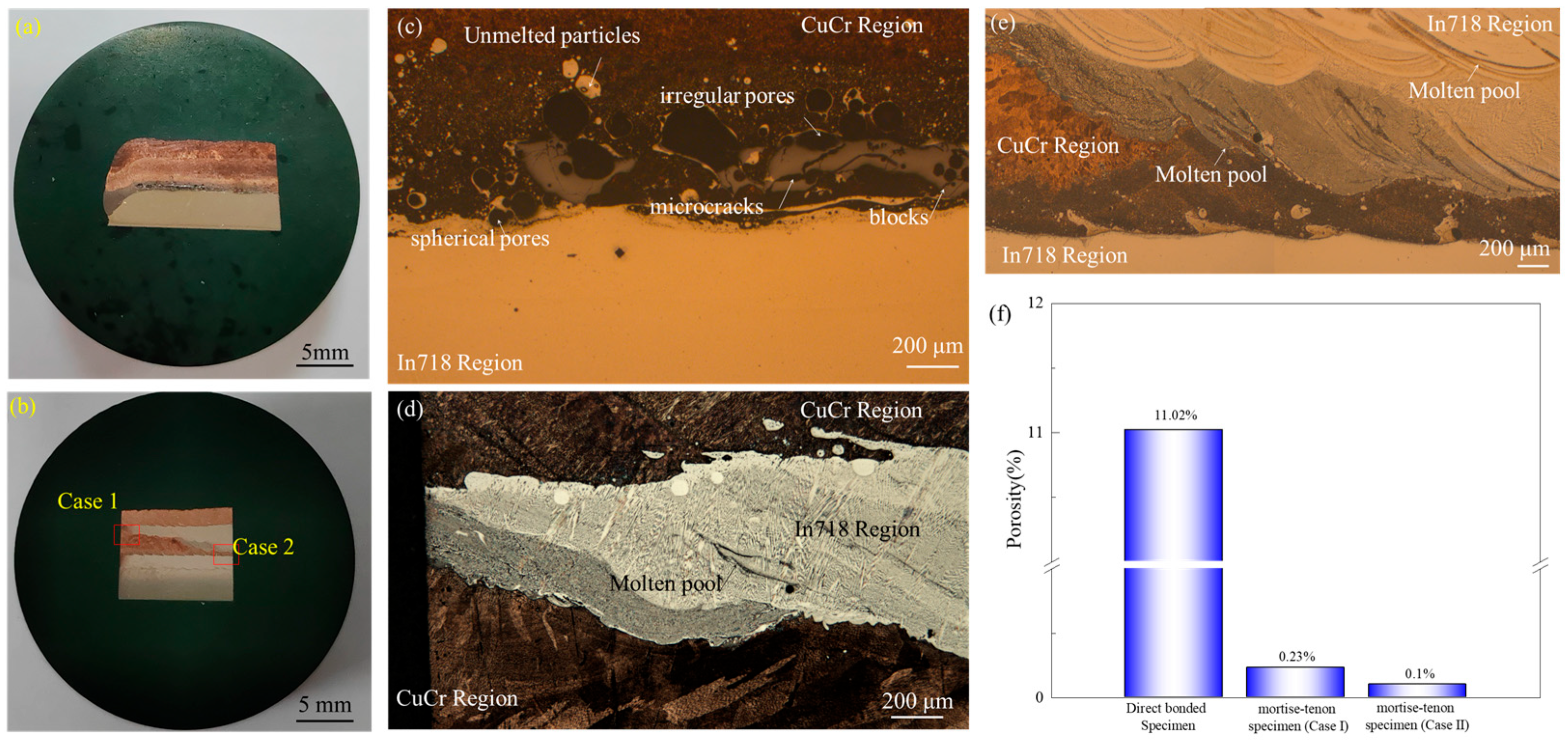
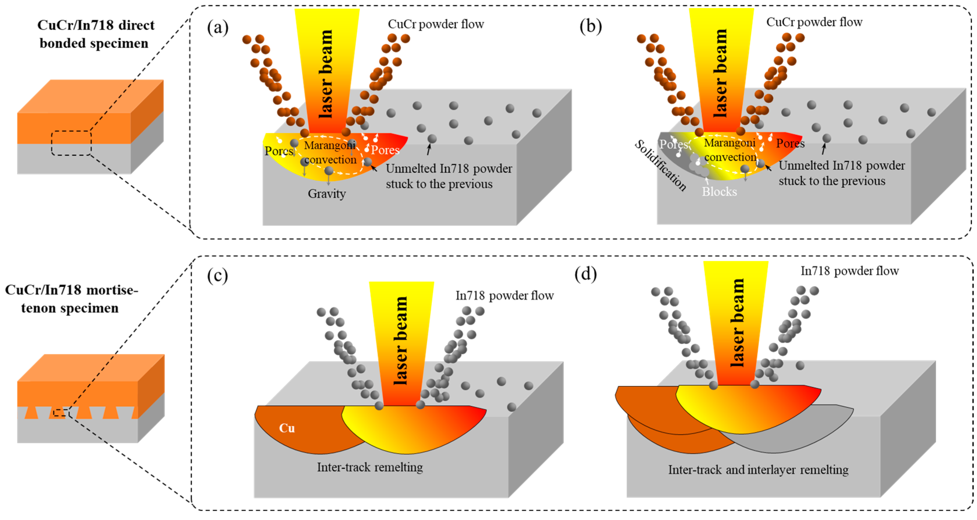
For the direct-bonded specimen, unmelted spherical Ni-rich particles, spherical and irregular shape pores, microcracks, and blocks were formed at the interface because the remelting of CuCr on In718 was not enough. In contrast, no naked defects could be observed at the interface of the mortise-tenon specimen due to the alternating inter-track and inter-layer remelting during the deposition of the mortise-tenon structure.
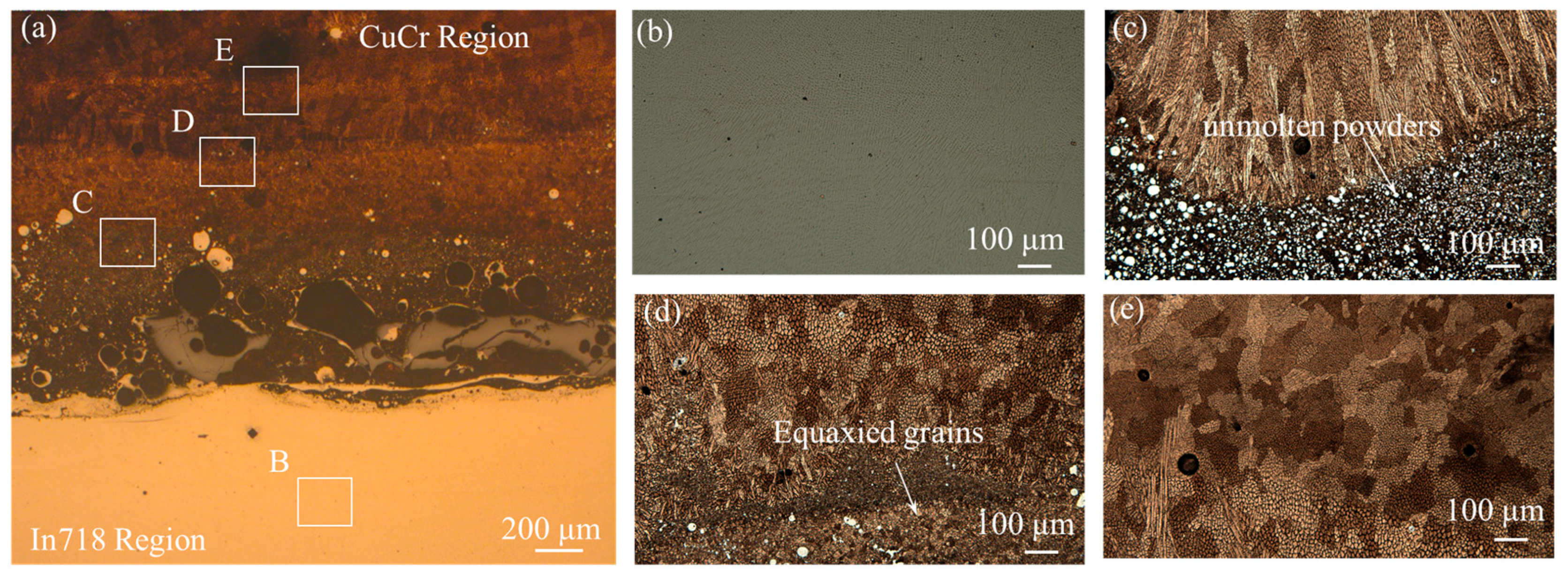
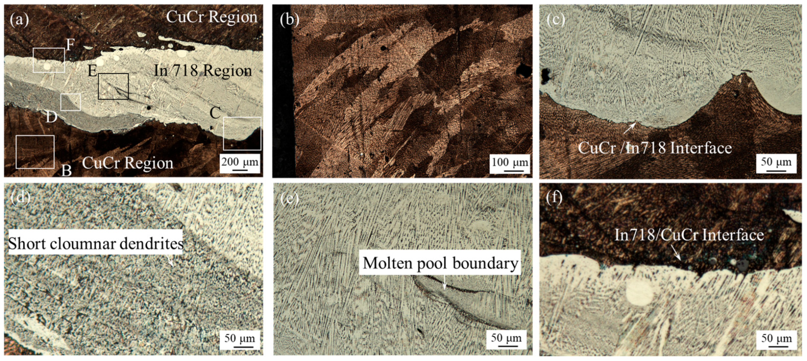
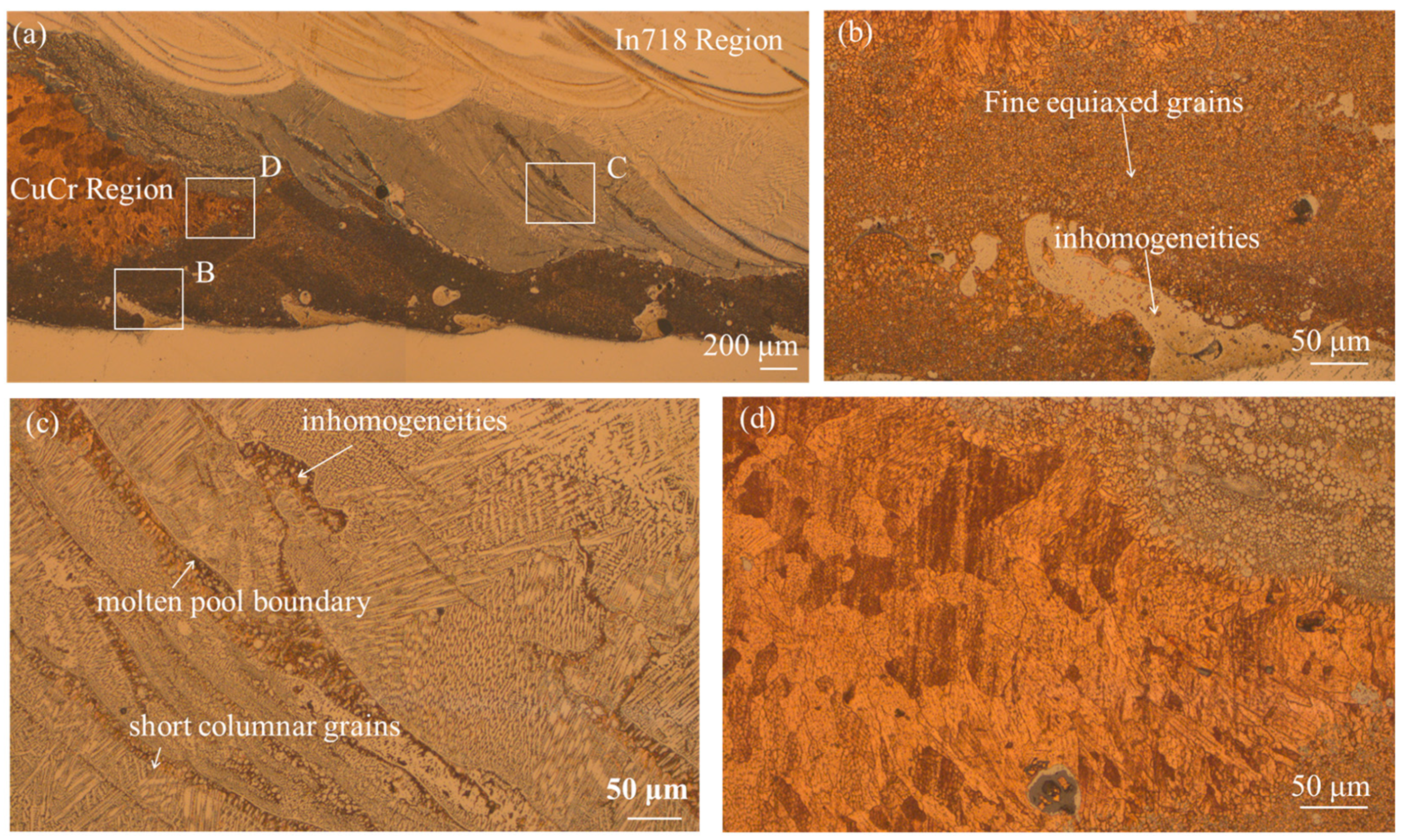
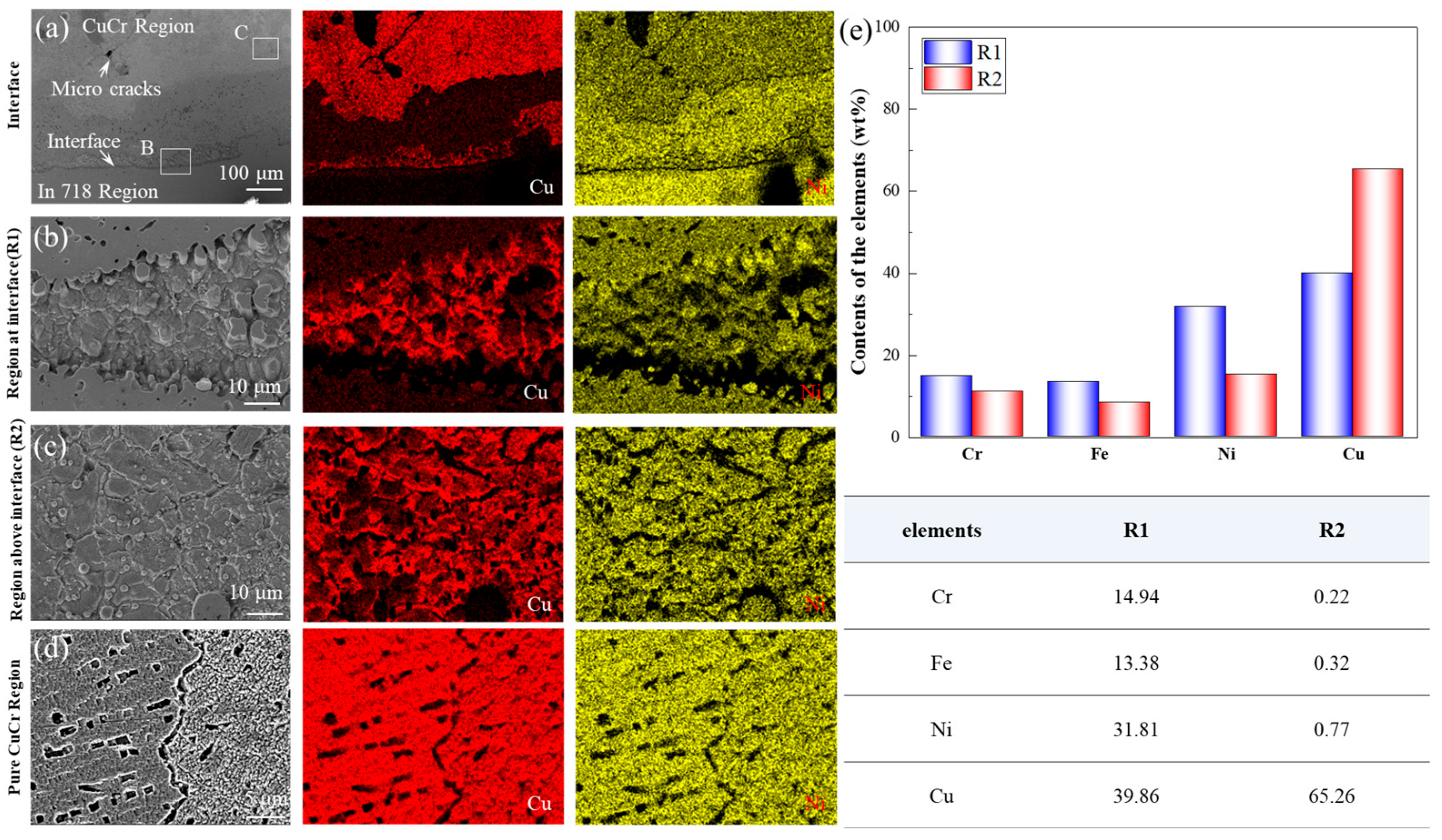
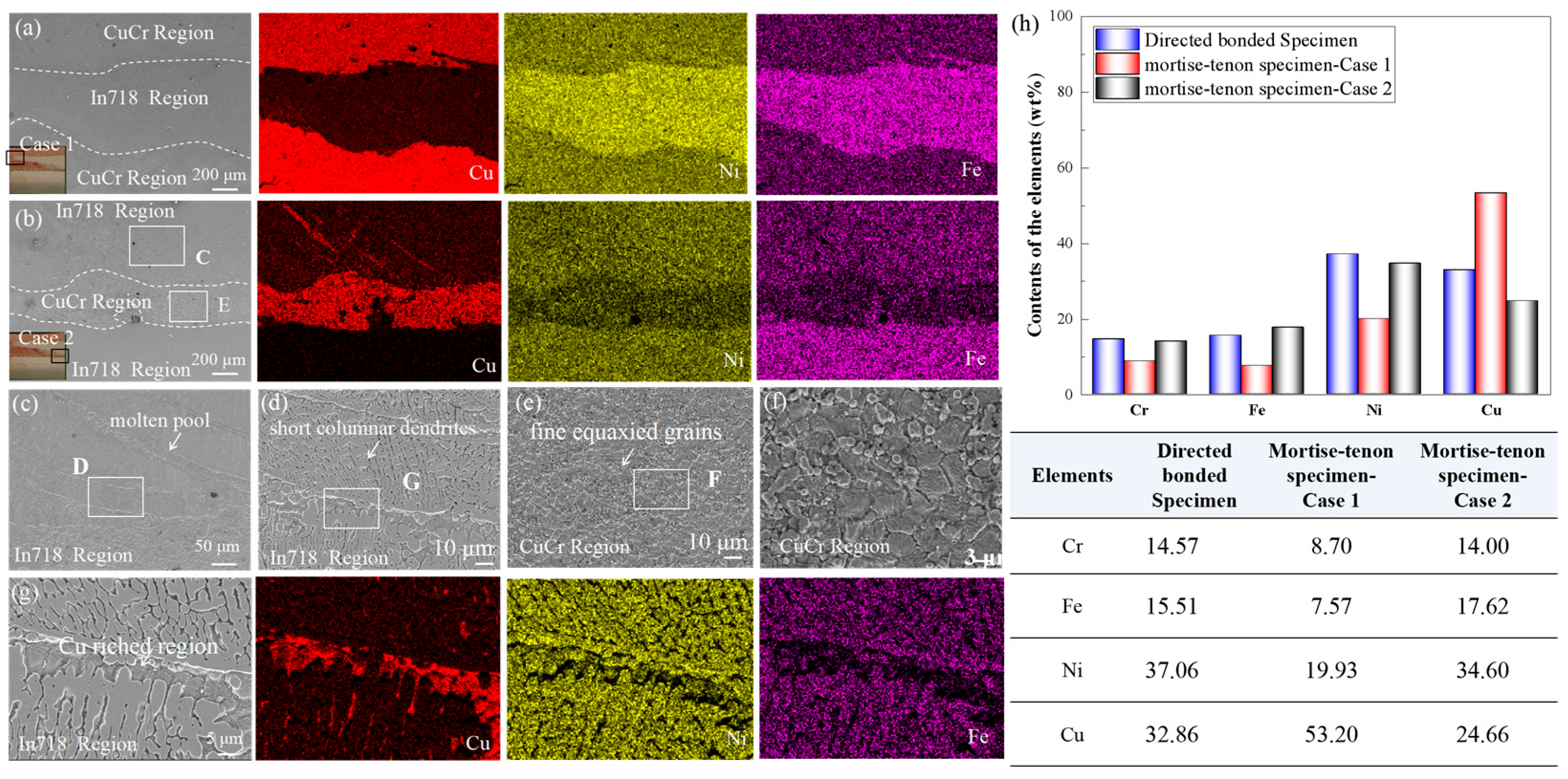
(2)
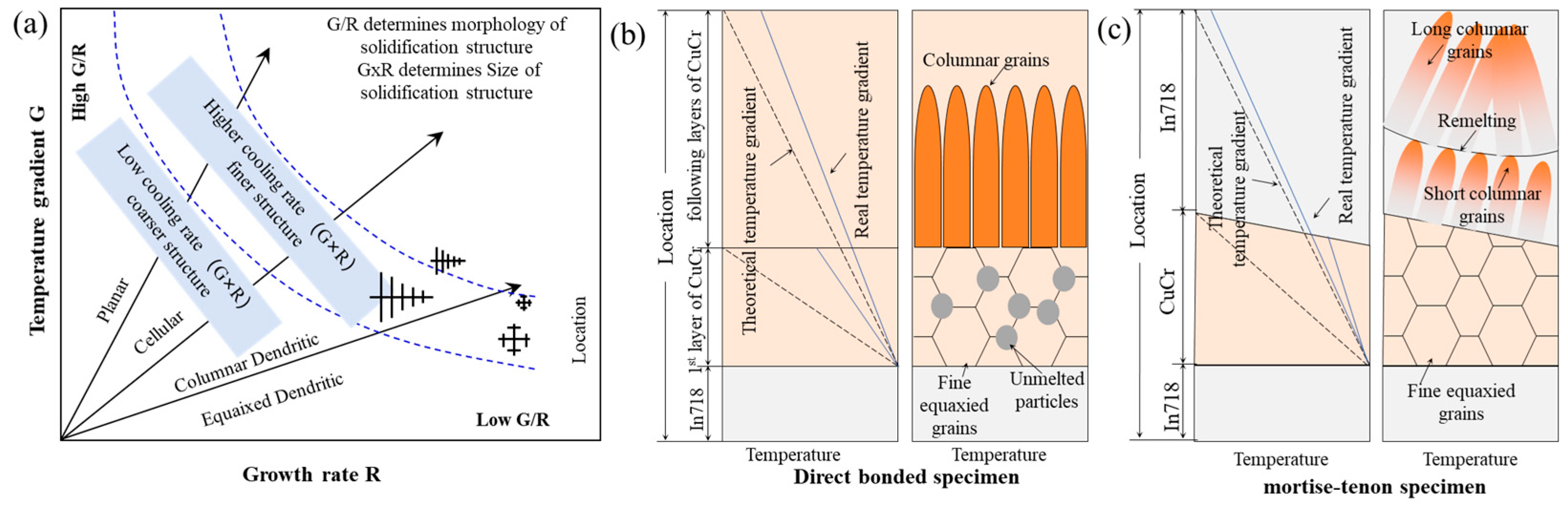
More obvious Cu elemental diffusion can be observed in the molten pool boundaries of the mortise-tenon interface. The sandwich-shaped fine equiaxed-columnar grains were formed in the direct-bonded specimen because of the high thermal conductivity of CuCr and continuous heat accumulation in powder DED-LB. The heterogeneous microstructure consisting of large columnar grains, short columnar grains, and fine equiaxed grains is formed in the mortise-tenon specimen due to the high thermal conductivity of the CuCr, remelting of In718, and Cu elemental diffusion.
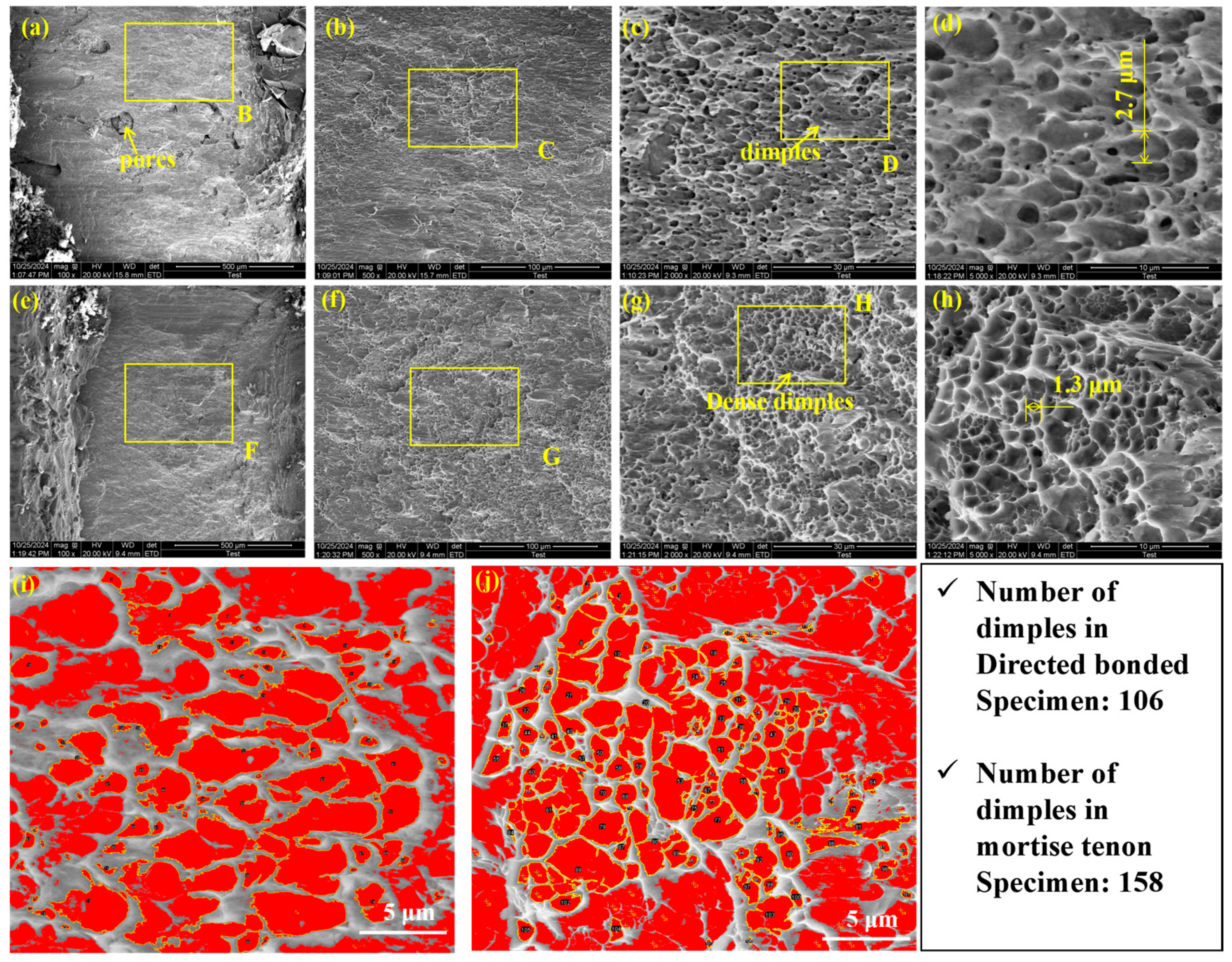
(3)
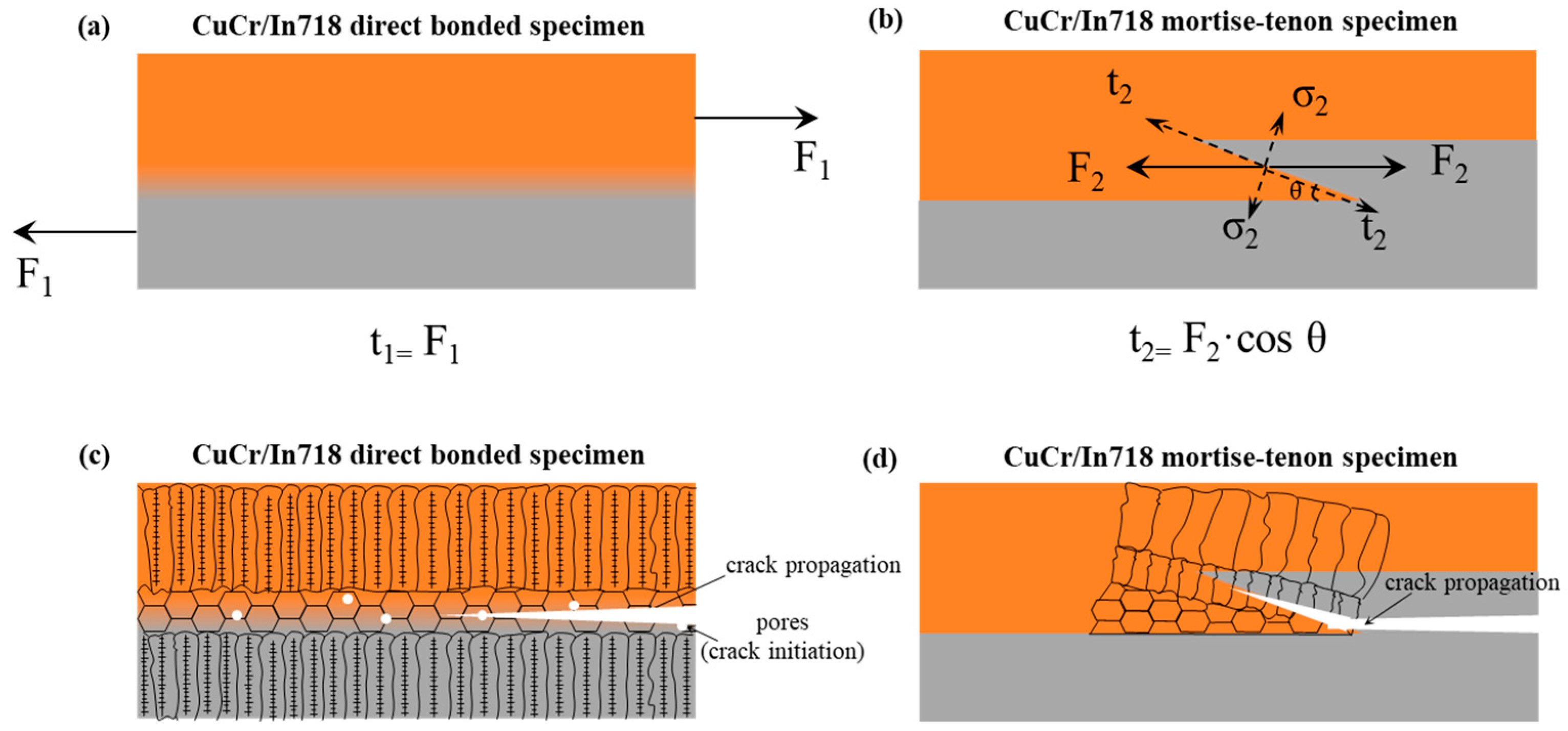
The metallurgical bonding strength of the mortise-tenon specimen was better than that of the direct-bonded specimen because its remelting-induced elemental diffusion was significantly increased. The mortise-tenon macroscopic morphology makes the shear load smaller and crack propagation difficult. Furthermore, the smaller grain size of the heterogeneous microstructure in the mortise-tenon specimen leads to greater strength. Hence, the shear strength was increased by 45.34% by depositing a mortise-tenon structure at the interface.

Author Contributions

Conceptualization, H.Z. and G.X.; Methodology, H.Z.; Writing—original draft preparation, G.X.; Writing—review and editing, H.Z. and G.X.; Funding acquisition, G.X. and H.Z. All authors have read and agreed to the published version of the manuscript.

Funding

This research was funded by the China Postdoctoral Science Foundation (No. 2023M741427) and China Postdoctoral Science Foundation (No. 2022M711385).

Data Availability Statement

The original contributions presented in this study are included in the article. Further inquiries can be directed to the corresponding authors.

Conflicts of Interest

The authors declare no conflicts of interest.

Abbreviations

The following abbreviations are used in this manuscript:
Powder DED-LBLaser-Based Direct Energy Deposition (DED-LB) using Pow-der Feedstock
DMsDissimilar materials
USSultimate shear strength
FE-SEMField emission scanning electron microscope
EDSEnergy dispersive spectroscopy
EBSDElectron backscatter diffraction

References

  1. Yao, X.J.; Zhu, Y.Y.; Han, X.; Yang, J.W.; Chen, L.; Wang, X.Y.; Wang, H.M. Preparation of copper/nickel dissimilar metals by laser additive manufacturing based on copper alloy surface pretreatment. Chin. J. Lasers 2025, 52, 0402301. [Google Scholar]
  2. Paul, G.L.; Omar, R.M.; Colton, K.; Timothy, M.S.; Jeff, S.; Alison, P.; Chen, P.S.; Darren, C.T.; Christopher, P.; Tom, T.; et al. Advancement of extreme environment additively manufactured alloys for next generation space propulsion applications. Acta Astronaut. 2023, 211, 483–497. [Google Scholar]
  3. Tran, T.Q.; Chinnappan, A.; Lee, J.K.Y.; Loc, N.H.; Tran, L.T.; Wang, G.; Kumar, V.V.; Jayathilaka, W.A.D.M.; Ji, D.; Doddamani, M.; et al. 3D printing of highly pure copper. Metals 2019, 9, 756. [Google Scholar] [CrossRef]
  4. Sun, Z.; Karppi, R. The application of electron beam welding for the joining of dissimilar metals: An overview. J. Mech. Work. Technol. 1996, 59, 257–267. [Google Scholar] [CrossRef]
  5. Chen, H.-C.; Pinkerton, A.J.; Li, L. Fibre laser welding of dissimilar alloys of Ti-6Al-4V and Inconel 718 for aerospace applications. Int. J. Adv. Manuf. Technol. 2011, 52, 977–987. [Google Scholar] [CrossRef]
  6. Xue, P.; Ni, D.; Wang, D.; Xiao, B.; Ma, Z. Effect of friction stir welding parameters on the microstructure and mechanical properties of the dissimilar Al–Cu joints. Mater. Sci. Eng. A 2011, 528, 4683–4689. [Google Scholar] [CrossRef]
  7. Guo, Y.; Liu, G.; Jin, H.; Shi, Z.; Qiao, G. Intermetallic phase formation in diffusion-bonded Cu/Al laminates. J. Mater. Sci. 2011, 46, 2467–2473. [Google Scholar] [CrossRef]
  8. Huang, X.; Dong, X.; Ma, J.; Liu, K.; Ahmed, S.; Lin, J.; Ahmad, F.; Qiu, B. Evaluation and Experiment of Flight Parameter Quality of the Plant Protection UAV Based on Laser Tracker. Agriculture 2021, 11, 628. [Google Scholar] [CrossRef]
  9. Shen, Y.; Zhu, H.; Liu, H.; Chen, Y.; Ozkan, E. Development of a Laser-Guided, Embedded-Computer-Controlled, Air-Assisted Precision Sprayer. Trans. ASABE 2017, 60, 1827–1838. [Google Scholar] [CrossRef]
  10. Liu, H.; Zhu, H.P. Evaluation of a Laser Scanning Sensor in Detection of Complex-Shaped Targets for Variable-Rate Sprayer Development. Trans. ASABE 2016, 59, 1181–1192. [Google Scholar]
  11. Bandyopadhyay, A.; Heer, B. Additive manufacturing of multi-material structures. Mater. Sci. Eng. R Rep. 2018, 129, 1–16. [Google Scholar] [CrossRef]
  12. Gu, D.; Shi, X.; Poprawe, R.; Bourell, D.L.; Setchi, R.; Zhu, J. Material-structure-performance integrated laser-metal additive manufacturing. Science 2021, 372, 932. [Google Scholar] [CrossRef] [PubMed]
  13. Lu, Y.; Xu, W.; Leng, J.; Liu, X.; Xu, H.; Ding, H.; Zhou, J.; Cui, L.F. Review and Research Prospects on Additive Manufacturing Technology for Agricultural Manufacturing. Agriculture 2024, 14, 1207. [Google Scholar] [CrossRef]
  14. Gradl, P.R.; Teasley, T.W.; Protz, C.S.; Garcia, M.B.; Ellis, D.; Kantzos, C. Advancing GRCop-based Bimetallic Additive Manufacturing to Optimize Component Design and Applications for Liquid Rocket Engines. In Proceedings of the AIAA Propulsion and Energy 2021 Forum, Virtual Event, 9–11 August 2021; p. 3231. [Google Scholar]
  15. Chang, T.; Fang, X.; Zhou, Y.; Zhang, H.; Xi, N.; Ghafoor, S.; Huang, K. Heterogeneous interfaces of aluminum bronze/Inconel 718 dissimilar alloys under different wire arc directed energy deposition sequences. Int. J. Extreme Manuf. 2025, 7, 015003. [Google Scholar] [CrossRef]
  16. Sutton, G.P.; Biblarz, O. Fundamentals of Rocket Propulsion; Beijing Institute of Technology Press: Beijing, China, 2019. [Google Scholar]
  17. Onuike, B.; Bandyopadhyay, A. Bond strength measurement for additively manufactured Inconel 718-GRCop84 copper alloy bimetallic joints. Addi Manuf. 2019, 27, 576–585. [Google Scholar] [CrossRef]
  18. Ryan, A.; Jordan, T.; Judy, S.; Sean, T.; Gual, P. Characteristics of bi-metallic interfaces formed during direct energy deposition additive manufacturing processing. Metall. Mater. Trans. B 2022, 50, 1925. [Google Scholar]
  19. Zhang, B.; Xiao, H.; Zhang, W.; Yang, H.; Wang, Y.; Peng, D.; Zhu, H.; Chen, B. Influence of the thermal conductivity of different CuCr0.8 substrate state on the formability of laser directed energy deposition Inconel718 single track. Mater. Charact. 2023, 202, 113015. [Google Scholar] [CrossRef]
  20. Foteinopoulos, P.; Papacharalampopoulos, A.; Stavropoulos, P. Additive manufacturing simulations: An approach based on space partitioning and dynamic 3D mesh adaptation. Addit. Manuf. Lett. 2024, 11, 100256. [Google Scholar] [CrossRef]
  21. Wei, C.; Liu, L.; Cao, H.; Zhong, X.; Xu, X.; Gu, Y.; Cheng, D.; Huang, Y.; Li, Z.; Guo, W.; et al. Cu10Sn to Ti6Al4V bonding mechanisms in laser-based powder bed fusion multiple material additive manufacturing with different build strategies. Addit. Manuf. 2022, 51, 102588. [Google Scholar] [CrossRef]
  22. He, Y.; Zhang, X.; Zhao, Z.; Xu, S.; Xia, M.; Zhang, C.; Hu, Y. Wire-feed laser additive manufacturing of dissimilar metals via dual molten pool interface interlocking mechanism. Sci. China Technol. Sci. 2023, 66, 976–986. [Google Scholar] [CrossRef]
  23. Chueh, Y.-H.; Wei, C.; Zhang, X.; Li, L. Integrated laser-based powder bed fusion and fused filament fabrication for three-dimensional printing of hybrid metal/polymer objects. Addit. Manuf. 2020, 31, 100928. [Google Scholar] [CrossRef]
  24. Judd, J.P.; Fonseca, F.S.; Walker, C.R.; Thorley, P.R. Tensile Strength of Varied-Angle Mortise and Tenon Connections in Timber Frames. J. Struct. Eng. 2012, 138, 636–644. [Google Scholar] [CrossRef]
  25. Hu, J.; Qiu, Y.; Wang, X.; Jiang, L.; Lu, X.; Li, M.; Wang, Z.; Pang, K.; Tian, Y.; Zhang, W.; et al. Flexible six-dimensional force sensor inspired by the tenon-and-mortise structure of ancient Chinese architecture for orthodontics. Nano Energy 2022, 96, 107073. [Google Scholar] [CrossRef]
  26. Zhu, Y.; Gao, D.; Shao, Y.; Chen, H.; Yu, C.; Wang, Q. A novel prefabricated auxetic honeycomb meta-structure based on mortise and tenon principle. Compos. Struct. 2024, 329, 117782. [Google Scholar] [CrossRef]
  27. Zhou, S.; Liu, H.; Li, B.; Yang, X.; Yang, J. A detachable chain tensile energy absorber inspired by mortise and tenon joint. Int. J. Mech. Sci. 2022, 223, 107290. [Google Scholar] [CrossRef]
  28. Yan, H.; Xie, S.; Zhang, F.; Jing, K.; He, L. Sound absorption performance of honeycomb metamaterials inspired by mortise-and-tenon structures. Appl. Acoust. 2025, 228, 110292. [Google Scholar] [CrossRef]
  29. Mills, K. Recommended Values of Thermophysical Properties for Selected Commercial Alloys; Woodhead Publishing: Cambridge, UK, 2001. [Google Scholar]
  30. Xu, G.; Wu, R.; Luo, K.; Lu, J. Effects of heat treatment on hot corrosion behavior of directed energy deposited In718/316L functionally graded material. Corros. Sci. 2022, 197, 110068. [Google Scholar] [CrossRef]
  31. Kuai, Z.; Li, Z.; Liu, B.; Chen, Y.; Lu, S.; Tang, X.; Liu, T. Selective laser melting of CuCrZr alloy: Processing optimisation, microstructure and mechanical properties. J. Mater. Res. Technol. 2022, 19, 4915–4931. [Google Scholar] [CrossRef]
  32. Liu, X.; Tan, C.; Zhang, J.; Hu, Y.; Ma, H.; Wang, F.; Cai, H. Influence of microstructure and strain rate on adiabatic shearing behavior in Ti–6Al–4V alloys. Mater. Sci. Eng. A 2009, 501, 30–36. [Google Scholar] [CrossRef]
  33. Sun, Y.; Li, X.; Yu, X.; Ge, D.; Chen, J.; Chen, J. Fracture Morphologies of Advanced High Strength Steel During Deformation. Acta Met. Sin. English Lett. 2014, 27, 101–106. [Google Scholar] [CrossRef]
  34. Sui, S.; Tan, H.; Chen, J.; Zhong, C.; Li, Z.; Fan, W.; Gasser, A.; Huang, W. The influence of Laves phases on the room temperature tensile properties of Inconel 718 fabricated by powder feeding laser additive manufacturing. Acta Mater. 2019, 164, 413–427. [Google Scholar] [CrossRef]
  35. Wei, H.; Knapp, G.; Mukherjee, T.; DebRoy, T. Three-dimensional grain growth during multi-layer printing of a nickel-based alloy Inconel 718. Addit. Manuf. 2019, 25, 448–459. [Google Scholar] [CrossRef]
  36. Wang, H.Y.; Lu, W.; Liu, J.H. Effects of high pressure heat treatment on the thermal physical properties of aluminum bronze. Chin. J. High Press. Phys. 2010, 24, 300–304. [Google Scholar]
  37. Zhang, Q.W.; Wang, X.T.; Qin, Y.; He, G.N.; Zhang, S.Y.; Huang, K.L.; Wang, J. Improving thermal conductivity of a nickel-based alloy through advanced electromagnetic coupling treatment. J. Mater. Res. Technol. 2022, 21, 4708–4723. [Google Scholar] [CrossRef]
  38. Liu, L.; Wang, D.; Wang, T.; Han, C.; Li, Y.; Tan, H.; Zhou, W.; Yan, X.; Lei, L.; Yang, Y. Laser additive manufacturing of multimaterials with hierarchical interlocking interface via a flexible scraper-based method. Int. J. Mach. Tools Manuf. 2025, 205, 104236. [Google Scholar] [CrossRef]
  39. Tey, C.F.; Tan, X.; Sing, S.L.; Yeong, W.Y. Additive manufacturing of multiple materials by selective laser melting: Ti-alloy to stainless steel via a Cu-alloy interlayer. Addit. Manuf. 2020, 31, 100970. [Google Scholar] [CrossRef]
  40. Wei, W.; Yongqiang, Y.; Guishengi, M.; Di, W.; Changhui, S. Free manufacturing of heterogeneous materials part by selective laser melting. Opt. Precis. Eng. 2019, 27, 517–526. [Google Scholar] [CrossRef]
  41. Xu, G.; Wu, L.; Su, Y.; Wang, Z.; Luo, K.; Lu, J. Microstructure and mechanical properties of directed energy deposited 316L/Ti6Al4V functionally graded materials via constant/gradient power. Mater. Sci. Eng. A 2022, 839, 142870. [Google Scholar] [CrossRef]
Figure 1. Application scenarios of mortise and tenon. (a) The pagoda with mortise-and-tenon structure, (b) enlarged image of the dashed circle in (a), and (c) the schematic diagram of the mortise and tenon structure. Adapted with permission from Ref. [28]. Elsevier 2025.
Metals 15 00557 g001
Figure 2. (a) Inspiration from mortise and tenon structure, (b) powder DED-LBed CuCr/In718 mortise and tenon structure, (c) photo of powder DED-LB system, SEM image and corresponding EDS mapping of (d) CuCr and (e) In718 powders, (f) schematic of CuCr/In718 mortise and tenon structure deposition process. Adapted with permission from Ref. [28]. Elsevier 2025.
Metals 15 00557 g002
Figure 3. The morphology of copper alloy single tracks under different laser power: (a) 1400 W, (b) 1600 W, (c) 1800 W, and (d) 2000 W.
Metals 15 00557 g003
Figure 4. Dimensions of shear test samples cutting from (a) direct-bonded specimen and (b) mortise-tenon specimen.
Metals 15 00557 g004
Figure 5. (a,b) photos of cross section of direct-bonded and mortise-tenon specimens, (c) defects at the interface of direct-bonded specimen, (d,e) enlarged images of Case I and II at the interface of mortise-tenon specimen, (f) porosity of direct-bonded, Case I and II of mortise-tenon specimens.
Metals 15 00557 g005
Figure 6. (a) Overall OM image of the interface of the direct-bonded specimen, enlarged images of (b) Rectangle B marked at pure In718 Region, (c,d) Rectangles C and D marked at the interface, and (e) Rectangles E marked at pure CuCr Region.
Metals 15 00557 g006
Figure 7. (a) Overall OM images of Case I in the mortise-tenon specimen interface. (bf) Enlarged images of Rectangles B–F marked in (a): (b) Rectangle B marked in pure CuCr Region, (c) Rectangle C marked at the CuCr/In718 interface, (d,e) Rectangles D and E marked in pure In718 Region, and (f) Rectangles F marked at the In718/CuCr interface.
Metals 15 00557 g007
Figure 8. (a) Overall OM images of Case II in the mortise-tenon specimen interface. (b) enlarged images of Rectangle B at the interface, (c,d) enlarged images of Rectangles C and D in Pure In718 and CuCr Regions.
Metals 15 00557 g008
Figure 9. (a) SEM image and corresponding EDS mapping results of interface in direct-bonded specimen, (b) enlarged SEM image EDS mapping of Rectangle R1 in (a), (c) enlarged SEM image of Rectangle R2 in (a), and (d) SEM image and corresponding EDS mapping results of pure CuCr Region, (e) elemental distributions of Cr, Fe, Ni and Cu of two regions in direct-bonded specimen.
Metals 15 00557 g009
Figure 10. SEM image and corresponding EDS mapping results of interface in mortise-tenon specimen: (a) Case I, (b) Case II, (c,d) enlarged images of Rectangles C and D in Figure 8b,c, (e) enlarged image of Rectangle E in (b), (f) enlarged image of Rectangle F in (e), (g) enlarged image of Rectangle G in (d), (h) elemental distributions of Cr, Fe, Ni and Cu of two cases in mortise-tenon specimen and directed bonded specimen.
Metals 15 00557 g010
Figure 11. (a) The IPF map, (b) phase distributions, (c) EDS mapping of interface in direct-bonded specimen, (d) IPF map, (e) grain boundary distribution, (f) phase distribution of Rectangle D in (a), (g) pole figure maps and (h) grain size distribution of Cu (CuCr region) and Ni phases (In718 region).
Metals 15 00557 g011
Figure 12. (a) The IPF map, (b) phase distributions, (c) EDS mapping of interface in mortise-tenon specimen, (d) IPF map, (e) grain boundary distribution, (f) phase distribution of Rectangle D in (a), (g) pole figure maps and (h) grain size distribution of Cu (CuCr region) and Ni phases (In718 region).
Metals 15 00557 g012
Figure 13. (a) Shear stress-strain curves and (b) corresponding shear strengths of direct-bonded and mortise-tenon specimens.
Metals 15 00557 g013
Figure 14. Overall fracture morphology of (a) direct-bonded and (e) mortise-tenon specimens, (bd) magnifications of Rectangle B, Rectangle C, and Rectangle D in (ac), respectively; (fh) magnifications of Rectangle F, Rectangle G, and Rectangle H in (eg), respectively; (i,j) quantified images to count the dimples in (d,h) using ImageJ software.
Metals 15 00557 g014
Figure 15. Schematic diagrams of the deposition process of (a,b) direct-bonded and (c,d) mortise-tenon specimens.
Metals 15 00557 g015
Figure 16. (a) The influence of the temperature gradient G and growth rate R on the microstructure, schematic diagrams of microstructural evolution of (b) direct-bonded and (c) mortise-tenon specimens.
Metals 15 00557 g016
Figure 17. (a,b) The stress analysis and (c,d) crack propagation during shear test of two specimens: (a,c) direct-bonded and (b,d) mortise-tenon specimens.
Metals 15 00557 g017
Table 1. Summary of current research on dissimilar materials.
Problems in Additive Manufacturing of Nickel/Copper Dissimilar Alloys
AuthorMethodMaterialsProblemsConclusion
Onuike et al. [17].Powder DED-LBGRCop-84 and In718Shear strength of the bimetallic is smaller than the matrixDefects and poor strength of interface are common issues in copper and Inconel dissimilar alloys
Ryan et al. [18].DED-LB and wire-fed processesInconel and C18150pores and unmelted particles
Methods to improve the property of dissimilar alloys
Process parameters optimization
AuthorMethodResultsLimitation and Research gap
Zhang et al. [19]Change the state of Copper substrate in DED-LBThermal conductivity has a significant effect on the formability and microstructure
(1)
The parameter optimization required a significant amount of time.
(2)
Parameter modification cannot achieve tailored interface microstructure and property design.
Chang et al. [15]Change the Deposition sequences in Wire arc DED of aluminum bronze/Inconel 718 dissimilar alloysCu-Ni demonstrates better interfacial property
Foteinopoulos et al. [20]Simulationsimulation is one of the most widely used methods for process optimization
Interfacial structure construction
AuthorMethodResultsLimitation and Research gap
Wei et al. [21]Using laser remelting at the interface of SLMed Ti6Al4V/Cu10Sn dissimilar alloys to build the keyhole structuresKeyhole structure can promote the elemental diffusion
(1)
The interfacial structure established at the interface is micron-scale.
(2)
The study only focused on the elemental diffusion and microstructural evolution induced by the micron-scale structure.
Hu et al. [22]Using dual lasers in wire-feed additive manufacturing of 7075-aluminum alloy/304-stainless steel dissimilar alloys to build the dimple structuresDimple structures can effectively reduce the intermetallic compound layer
Chueh et al. [23]Integrated fused filament fabrication (FFF) and laser-based powder bed fusion (PBF) to produce hybrid metal and polymer components with macroscopic interlocking structuresThe printed metal/polymer joints exhibited reliable strength by introducing macroscopic interlocking structures
(1)
The study only focused on the mechanical interlocking effect between macroscopic structures.
(2)
The dissimilar component is consisting of metal and polymer without metallurgical bond and microscopic reactions.
Table 2. The chemical composition of CuCr (wt%).
ElementCSCuCrPFeSn
Content0.01250.0034Bal.1.360.00470.00660.0041
Table 3. The chemical composition of In718 (wt%).
ElementCCuMnSiMoNbFeCrNi
Content0.040.120.271.043.315.4914.1920.67Bal.
Disclaimer/Publisher’s Note: The statements, opinions and data contained in all publications are solely those of the individual author(s) and contributor(s) and not of MDPI and/or the editor(s). MDPI and/or the editor(s) disclaim responsibility for any injury to people or property resulting from any ideas, methods, instructions or products referred to in the content.

