Article

Influence of Deposition Rate on Fatigue Behavior of 316L Stainless Steel Prepared via Hybrid Laser Wire Direct Energy Deposition

1
Department of Mechanical Engineering, Baylor University, Waco, TX 76798, USA
2
Point-of-Need Innovations (PONI) Center, Baylor University, Waco, TX 76798, USA
*
Author to whom correspondence should be addressed.
Metals 2025, 15(5), 543; https://doi.org/10.3390/met15050543
Submission received: 8 April 2025 / Revised: 8 May 2025 / Accepted: 10 May 2025 / Published: 14 May 2025
(This article belongs to the Section Additive Manufacturing)

Abstract

:
Hybrid additive manufacturing (AM) provides a unique way of fabricating complex geometries with onboard machining capabilities, combining both additive and traditional subtractive techniques and resulting in reduced material waste and efficient high-tolerance components. In this work, a hybrid AM technology was used to create 316L stainless steel (316L SS) components using laser-wire-directed energy deposition (LW-DED) coupled with a CNC machining center on a single platform. Fully reversed fatigue tests were completed to investigate the as-manufactured life span of the additively manufactured structures for three different deposition rates of 6.33 g/min, 7.12 g/min, and 7.91 g/min. High-cycle fatigue test results showed that the fatigue performance of the tested specimens is not dependent on the deposition rates for the investigated parameters, with specimens with a 7.12 g/min deposition rate showing comparatively superior behavior to that of the other deposition rates at higher stress amplitudes. Fractography analysis was used to investigate the fractured surfaces, showing that the crack initiation sites were predominantly near the edges and not affected by the volumetric defects generated during manufacturing. X-ray-computed tomography (X-ray CT) analysis quantified the effect of the as-manufactured porosity on fatigue behavior, showing that the amount of porosity for the build rates used was insufficient to have a substantial impact on the fatigue behavior, even as it increased with the deposition rate.

1. Introduction

Laser-directed energy deposition (LDED) is a popular branch of additive manufacturing that can facilitate the fabrication of functionally graded parts and repair complex geometries [1,2]. Among the forms of LDED, laser wire direct energy deposition (LW-DED) is capable of producing parts with efficient material use and a better surface finish at a comparatively lower cost than powder-fed laser direct energy deposition (LP-DED) [3,4]. In LW-DED processes, a metallic wire is fed into the nozzle coaxially with a laser beam that melts both the substrate and feedstock material, creating a melt pool and then the geometry by layer-by-layer deposition upon solidification. In addition to material deposition, LW-DED processes are often paired with subtractive capabilities to create a hybrid manufacturing system capable of rapidly producing complex components while meeting high tolerances.
One of the main advantages of LW-DED is its capability to handle higher deposition rates [5,6], which in turn can influence the fatigue behavior of metallic materials [7,8]. Notable works in the literature have focused on traditional printing parameters, different manufacturing approaches, and the conditions for using LW-DED technology [9,10]. Brubaker et al. [11] investigated the microstructures and properties of 316L SS with specimens prepared using LW-DED at different environmental conditions and showed the effect of different grain and dendrite conditions on morphology and mechanical behavior, including ductility and hardness. Gao et al. [12] introduced a hybrid LW-DED process by incorporating a single-point incremental-forming (SPIF) process using 316L SS and investigated different deformation zones by varying SPIF parameters. In this work, they were able to refine microstructure and twin boundary densities, resulting in higher corrosion resistance and hardness. Li et al. [13] investigated the effects of increased beam diameter and laser power on the microstructure and mechanical behavior of 316L SS specimens manufactured using LDED and improved the build rate by 78%, with efficient material usage of up to 132% per print, which can reduce porosity and enhance mechanical performance.
When considering materials of interest to AM applications, 316L stainless steel is widely used in different industries, including the automotive [14], aerospace [15], aeronautical [16], biomedical [17], nuclear [18], and many other industries because of its mechanical properties and excellent fatigue performance [19,20,21]. Given the performance and applicability of 316L, several efforts have explored approaches to improve the fatigue performance of 316L SS produced via DED, including heat and surface treatments, stress and corrosion mitigation, and impurity reduction [22,23]. Most of these available studies are based on the behavior and fatigue life of 316L SS using LP-DED [24,25], or other AM techniques [26] and material systems [27,28]. To date, studies focusing on LW-DED studies are limited in comparison, and the process–structure–property–performance (PSPP) relationships for LW-DED components prepared via hybrid manufacturing need to be further established to enable further adoption of this technology.
While the aforementioned works focused on the deposition process, as hybrid additive/subtractive manufacturing is a useful approach that can significantly reduce the time, cost, and logistics of additional machining steps, multiple efforts to date have investigated its ability to produce accurate geometries with high precision in an efficient manner [29]. Yang et al. [30] manufactured cavity and free-form structures using a hybrid DED technique with thermal milling to study the densification levels, microstructure, and mechanical behavior of 316L SS parts, showing high strengths with fewer defects. Ding et al. [31] manufactured cross and double-arc components with enhanced surface finishes and dimensional precision, studying the relationship between the microstructure, machinability, and mechanical behavior of 316L SS components prepared using a hybrid DED process. Luo et al. [32] studied the effect of residual stress on 316L components generated due to the multi-physics nature of the deposition and milling processes in hybrid DED manufacturing. Their efforts propose a method to measure deformation, transferred temperature, and residual stress during the manufacturing steps. The hybrid LW-DED technique has several advantages and the potential to advance the adoption of metal additive manufacturing in industry [33,34]. Although published works are available on the efficiency, finishing, dimensional aspects, as well as the mechanical behavior of components manufactured using 316L SS in the hybrid LW-DED technique, the fatigue performance of this prominent technique needs to be further explored to enable the use of these components in critical applications.
To further establish the process–structure–property–performance relationships for LW-DED with regard to fatigue performance, this work investigates the influence of the material deposition rate. As material deposition rates will directly affect production rates in point-of-need applications, it is important to understand any deleterious effects this has on this process’s ability to play a role in sustaining the supply chain. In this work, a hybrid laser wire DED technique has been used to create fatigue specimens using 316L SS at three different deposition rates to elucidate any effects that enhanced build rates may have on the functional fatigue performance of these components. Specimens were tested in an as-manufactured state to provide insights into the performance of the component directly coming off the machine, which is relevant for point-of-need applications. Fractography was completed using a scanning electron microscope (SEM) to investigate the fractured surfaces of the fatigue-tested specimens and identify sources of crack initiation. X-ray CT analysis was conducted to quantify the as-manufactured porosity level due to the varying deposition rates and was correlated with the fatigue performance of the components manufactured using this hybrid AM technique. This work provides insights into the PSPP for 316L SS components prepared via hybrid LW-DED for point-of-need applications and elucidates the effects of increasing production rates.

2. Materials and Methods

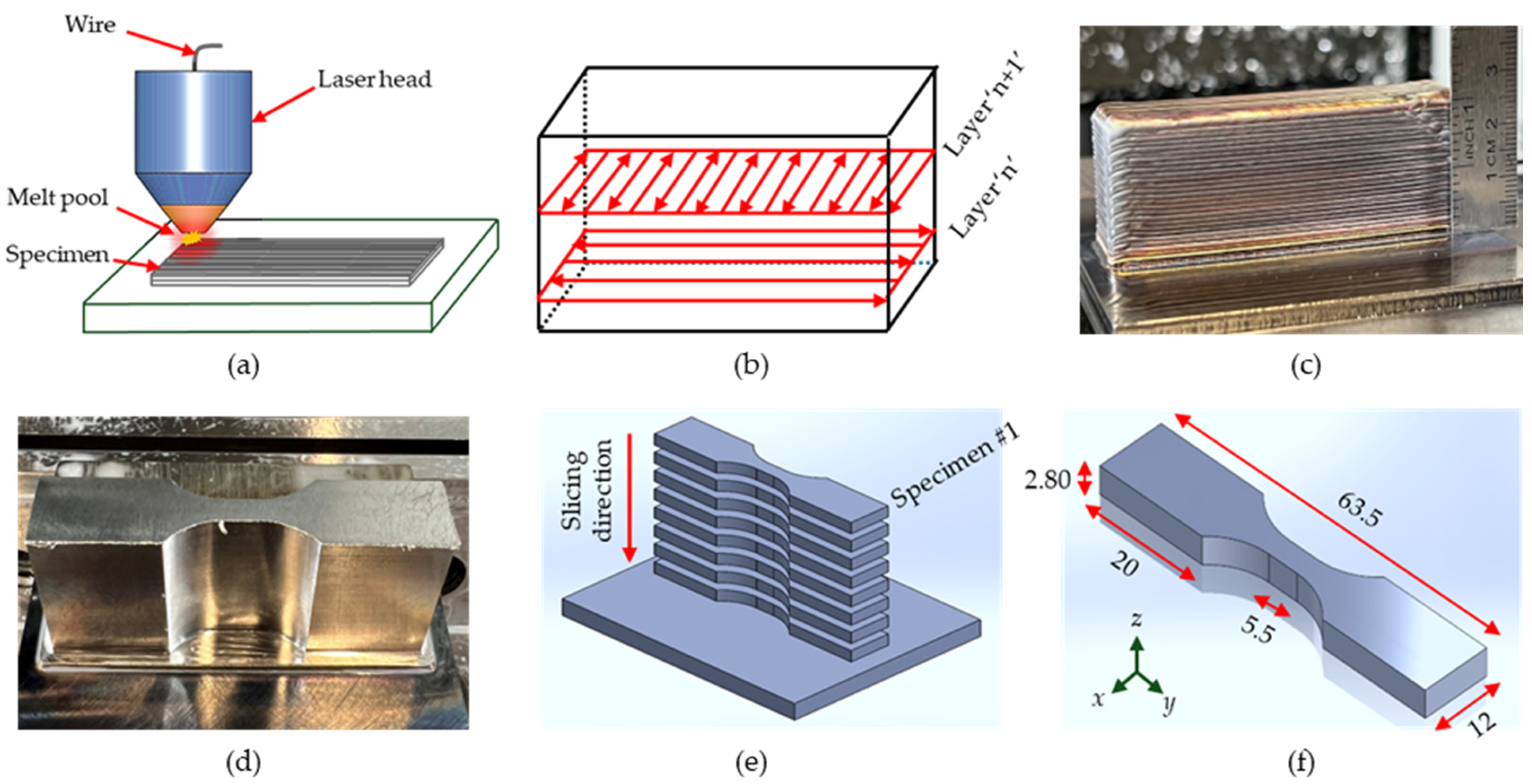
2.1. Specimen Preparation

The specimens used in this study were prepared in two main steps: (i) hybrid manufacturing (additive/subtractive) and (ii) specimen slicing. A typical schematic of a laser-wire-directed energy deposition (LW-DED) process is shown in Figure 1a, and Figure 1b represents the scanning strategy used during the manufacturing process.
As can be seen in Figure 1c, in the additive step, a 316L stainless steel wire feedstock, with a diameter of 1 mm, was used to manufacture rectangular blocks that are nominally 63.5 mm in length, 12.2 mm in width, and 25 mm in height on a steel substrate using a Phillips TM1 additive hybrid manufacturing machine (Phillips Corporation; Hanover, MD, USA). The mechanical properties of the MELTIO 316L stainless steel provided by the manufacturer are listed in Table 1.
In this study, varying wire feed rates were used while maintaining constant laser power. Phillips TM1 utilizes a MELTIO DED print head in conjunction with a CNC machine in the same unit to enable both the additive and subtractive manufacturing steps. The process parameters used in the additive step are listed in Table 2.
The volumetric ratio was kept constant by increasing the wire feed rates along with the traverse speeds to achieve higher deposition rates. A dwell time of 20 s was used after printing each layer for stable operation. When using LW-DED processes, it is important to maintain an inert environment to reduce oxidation and maintain the inherent properties of the metallic parts. As such, a 100% argon gas with a flow rate of 15 L per minute (lpm) was used coaxially with the material extruder during the deposition process. An alternating deposition pattern of 0° and 90° was used with a layer thickness of 0.95 mm. After the additive step, the printed block was allowed to cool down for an hour before the subtractive step was initiated. Intermediate machining was required in some cases to maintain appropriate clearance between the deposit and the print head at the edges of the block. In such cases, the deposited material was machined flat prior to the continuation of the print to the final build height. In traditional manufacturing processes, materials are removed from the as-built blocks using commercially available milling tools, sandpaper, or systems in a separate unit that increases material waste and labor, reducing the efficiency of the manufacturing approach. In this work, instead of using a separate unit, the integrated milling capability was adopted to subtract material from the printed rectangular blocks to obtain the geometric shape of a dog bone, as shown in Figure 1d. After the hybrid manufacturing step, the rectangular blocks were sliced in an MV1200-S (Mitsubishi Electric Corporation; Vernon Hills, IL, USA) high-precision wire-cut electrical discharge machine (EDM), as shown in Figure 1e, with a 0.25 mm wire, resulting in dog-bone specimens with dimensions matching [35], as shown in Figure 1f, with the exception of the specimen thickness for mechanical testing. Here, from each machined block, specimens were cut sequentially from top to bottom, going towards the substrate, using EDM. Figure 1f shows the dog bones sliced in the EDM with a length of 63.5 mm, a wide grip section of 12 mm, a thickness of 2.8 mm, a grip length of 20 mm, and a gauge length of 5.5 mm. The sliced specimens were then surface-finished with 240 and 600 grits of silicon carbide paper to eliminate the recast layer and provide a suitable surface finish for fatigue testing.

2.2. X-Ray Computed Tomography (CT)

An NSI X3000 (North Star Imaging Inc.; Rogers, MN, USA) system was used to perform the X-ray CT imaging for this investigation. To achieve the necessary beam intensity and contrast in the scans, an X-ray source with a 210 kV acceleration voltage and a current of 100 µA was employed. A focal spot size of 21 µm with a voxel size of 18.09 µm was used to generate the X-ray beam. Afterward, using the NSI’s efX-CT (version 2.3.7.5) software (North Star Imaging Inc.; Rogers, MN, USA), the raw CT scan data were rebuilt into virtual 2D slices. The sharpness and beam hardening settings were selected for each scan.

2.3. High-Cycle Fatigue (HCF) Testing Method

Fully reversed (stress ratio, R = −1) high-cycle fatigue tests were performed up to failure using a load-control approach at variable frequency ranges with stress amplitudes of 450, 400, 350, 300, and 250 MPa in five specimens manufactured using the process parameters listed in Table 2 for each type. One specimen was tested at each stress level for each deposition rate under cyclic loading conditions. Testing frequency was selected based on the applied load to avoid self-heating within the gauge at higher stress amplitudes. All tests were performed using a servohydraulic testing system (MTS Systems Corporation; Eden Prairie, MN, USA) with a 25 kN load cell with 10% tolerance and 1% sensitivity at ambient temperature and relative humidity.

2.4. Fractography Characterization Method

Fractography of the fractured surfaces was completed after fatigue testing using a FIB-SEM Versa 3D system (FEI Company; Hillsboro, OR, USA). Images of the fracture surface of the test specimens after the fatigue tests were taken to locate the crack initiation site, any existing defects, and crack propagation directions, as well as investigate the variations based on the deposition rates. All the fractured surfaces were sonicated in isopropanol for 10 min to get rid of any external impurities before viewing under the microscope.

3. Results and Discussion

3.1. Effect of Deposition Rate on Internal Porosity

This present study investigated the influence of deposition rate variations on defect generation and subsequent fatigue performance. Figure 2a, Figure 2b, and Figure 2c represent the top views of specimens with deposition rates of 6.33 g/min, 7.12 g/min, and 7.91 g/min, respectively. Additionally, Figure 2d represents the cross-section of the specimen deposited with a rate of 7.12 g/min (Type B).
CT scans were completed prior to any fatigue testing. Although traces of porosity were found at different locations of the specimens, only the ones in the gauge length were considered for the porosity calculation. Table 3 shows the comparison of porosity for the three types of specimens investigated.
As can be seen in the table, the representative specimen with a deposition rate of 6.33 g/min (Type A, with the manufacturer’s recommended parameters) did not show any porosity in the CT inspection. The specimen with a deposition rate of 7.91 g/min (Type C) showed the maximum amount of porosity, indicating an increase in the porosity percentage with the increase in deposition rate. The melt pool is created during the manufacturing process using LW-DED, which is a crucial factor for controlling the integrity of the manufactured structures [36]. However, even with the melt pool, porosity was generated and increased with the deposition rate in the investigated specimens due to the entrapped air or molten metal bubbles. With the increase in the deposition rate at constant laser power, the linear heat input decreased for the builds. With the lower heat input and same dwell time, builds with higher deposition rates are expected to cool faster than those with lower deposition rates. These changes in the cooling rate may have resulted in entrapped bubbles in the material, causing internal porosity. However, the porosity generated due to the variation of the deposition rate is insignificant compared to the volume of the investigated specimen and was demonstrated in the following section to be inconsequential to fatigue performance. Additionally, it is worth noting that an organized distribution of pores can be observed in the X-ray CT images, potentially due to the cross hatch alternating deposition pattern (0°/90°) used during the manufacturing process.

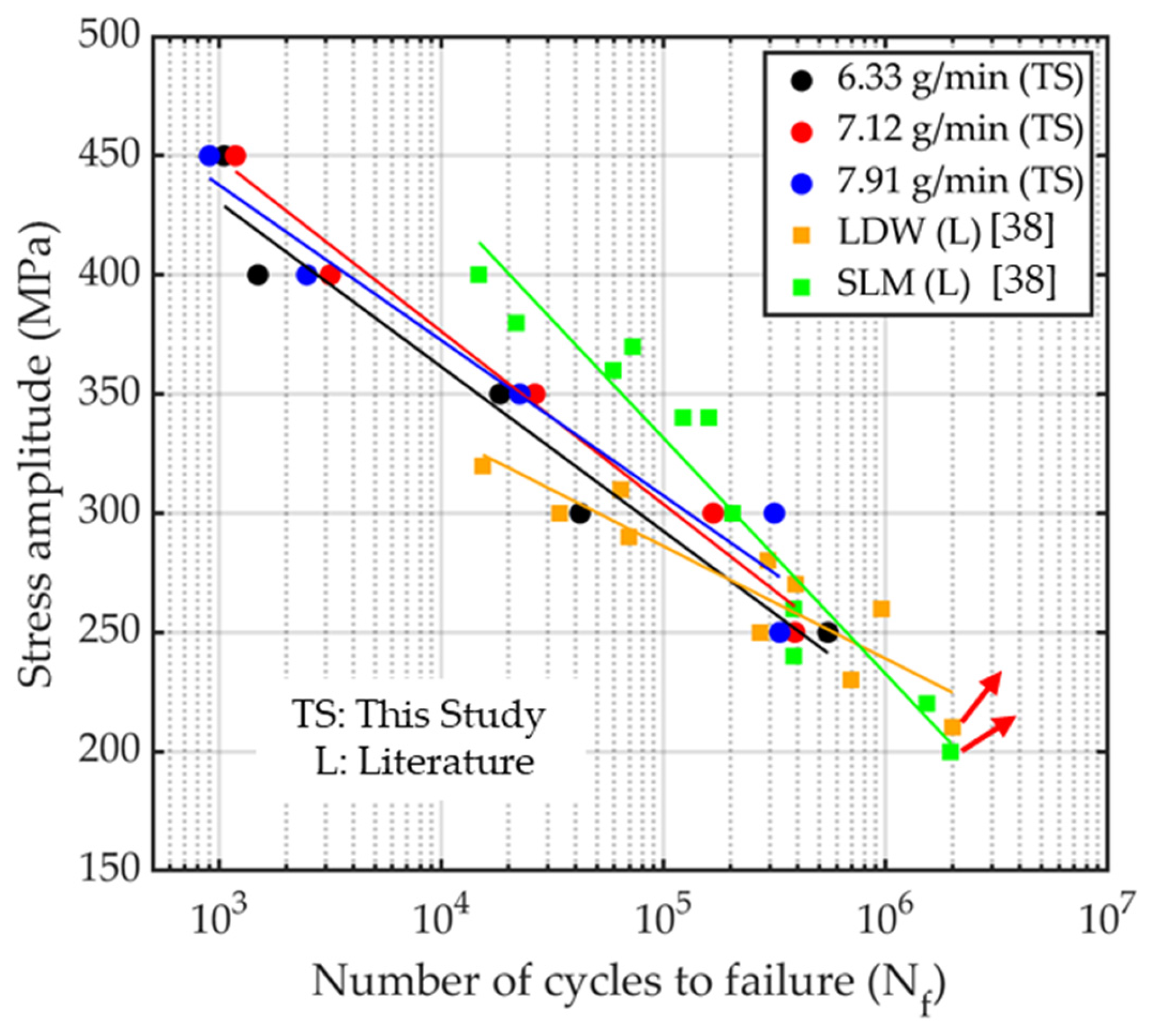
3.2. Influence of Deposition Rates on Fatigue Behavior

Figure 3 shows the experimental stress-life results for fully reversed (R = −1) fatigue tests with stress amplitudes (MPa) plotted against the number of cycles to failure for all three types of test specimens.
Five specimens of each type were tested using the load control approach and were allowed to fracture completely for further fractography analysis. The temperature was monitored during testing to maintain ambient testing conditions by varying the frequencies between 1–10 Hz based on the applied load values. The Basquin equation was used to fit the experimental data with the stress amplitude and cycles to failure [37]:
σ A = C ( N f ) b
where σ A is the stress amplitude, N f is the number of cycles to failure, C is the fatigue strength coefficient [MPa], and b is the strength exponent. The corresponding values of C and b as obtained from the fitted trendline are listed in Table 4 for each specimen type.
Figure 3. Plot representing the number of cycles to failure against the studied stress amplitudes for the three types of specimens. The red arrows indicate run-out conditions during the fatigue tests.
Metals 15 00543 g003
The high-cycle fatigue test results did not show a specific trend and displayed diverse behavior depending on the deposition rates. In general, specimens with a rate of 6.33 g/min (Type A) showed a lower number of cycles to failure than the other two types, with the exception of the minimum stress value tested (250 MPa). Specimens with a deposition rate of 7.12 g/min (Type B) had a longer fatigue life at higher stress levels compared to the other deposition rates; however, this comparative performance deteriorated at lower stresses. Among the three types, specimens prepared with a deposition rate of 7.91 g/min (Type C) showed the lowest number of cycles to failure (902 cycles) at the maximum studied amplitude (450 MPa). It should be noted that no specimens in this study experienced run-out for the stress levels investigated. Additionally, the amount of porosity observed in the specimens prepared in this study did not seem to have any correlation with fatigue performance. This is further corroborated by the fractography results presented in Section 3.3. The results from this study were compared with the study by Blinn et al. [38], which is plotted alongside the data from this work in Figure 3.
Blinn et al. [38] studied the fatigue behavior of specimens manufactured with 316L austenitic stainless steel using selective laser melting (SLM) and laser deposition welding (LDW) methods. Although their specimens were manufactured in both the horizontal and vertical directions, only the results from the horizontally printed specimens are compared in the present study in order to match the work performed herein. It should be noted that the specimen size in the referenced study was larger than in the present study; however, the authors believe that the comparison with the literature data can still provide a useful analysis. As shown in Figure 3, the specimens investigated in the present study showed similar or more cycles to failure at the same stress levels compared to the LDW process used in the referenced study. However, the specimens produced from SLM processing outperformed the present study at higher stress values, showing comparable results at lower stresses. This comparison indicates the feasible fatigue performance of 316L SS specimens manufactured using the hybrid AM technique compared to other existing manufacturing methods, while also being more feasible for point-of-need applications.

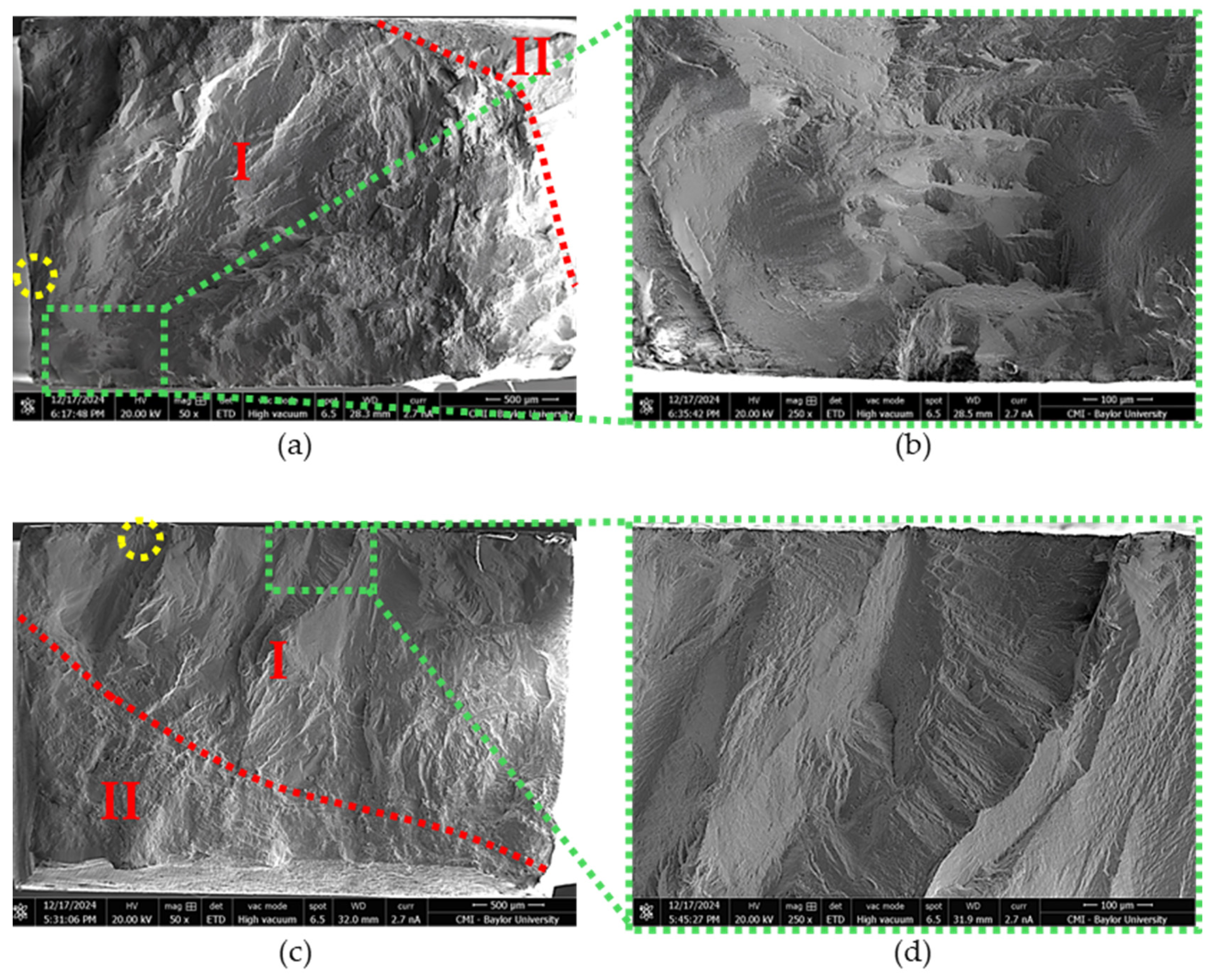
3.3. Fractography Results

As indicated in Figure 3, all the tested specimens showed comparable cycles to failure (Nf) based on the stress value applied for the three investigated types. Given that the specimens tested at 300 MPa exhibited the highest difference in cycles to failure, these specimens were chosen for fractography to investigate this disparity. These specimens showed a wide range of cycles to failure, in which Type A (6.33 g/min) failed at 42,038 cycles, Type B (7.12 g/min) failed at 166,962 cycles, and Type C (7.91 g/min) failed at 314,904 cycles. Figure 4 shows the images of the fractured surfaces for the different deposition rates. In all three cases, the fractured surfaces consisted of the crack propagation region (I) and the beach-like rapid fracture region (II), indicating ductile fracture.
As shown in Figure 4a, Type A (6.33 g/min) specimens had the smallest II regions, with the other two types of specimens showing larger II regions, agreeing with the obtained Nf values. The crack initiation sites were found near the edges of the tested specimens, shown in Figure 4b,d,f for the three cases, with uniform directions of crack propagation and river marks, as shown in Figure 4d,f. It should be noted that no significant pore sizes were found at the crack initiation location or along the crack propagation path. This aligns with the lack of a trend between porosity content and cycles to failure, as previously discussed. Additionally, multiple crack initiation sites were found, all of which were near the edges in all three types of specimens.
While it is generally recognized that porosity is detrimental to fatigue performance, the absence of a clear correlation between the volume of porosity in the gage section and the corresponding fatigue life within the present study warrants additional discussion. There are several potential reasons for the absence of a trend since the volume of porosity is not the sole driving force for fatigue life reduction, and the variation in porosity between the scanned specimens is less than 1%. The geometry of the pore and its orientation to the primary stress axis, its proximity to the free surface, and its distance to adjacent pores also influence the severity of the stress field around the pore and the degree of reduction in fatigue life It should also be reiterated that all specimens were tested in the as-printed condition, thus factors such as the residual stress distribution and microstructure, which are apt to vary spatially within each build and parameter set in the as-printed condition, would contribute additional variation to the fatigue performance. The absence of pores observed on the fracture surface during post-mortem analysis, in conjunction with the general lack of a correlation between measured porosity and fatigue life, suggests that porosity is not the dominant factor driving the fatigue performance of the hybrid manufactured part in the present study. Additional investigation is needed to both improve print consistency and identify the dominant mechanism(s) driving fatigue performance, and the fabrication of additional builds both within and outside the present process window may be required to achieve optimum fatigue performance.

4. Conclusions

In this work, hybrid AM technology was used with a laser wire DED process. 316L SS was used as the feedstock material deposited at three different deposition rates. Fatigue tests were performed on specimens from each build with subsequent post-mortem fractography of the fractured surfaces. High-cycle fatigue tests revealed that the fatigue performance of the tested specimens was not dependent on the deposition rates alone. However, of the three deposition rates considered, specimens deposited at a rate of 7.12 g/min showed slightly better performance than the other two at higher stress amplitudes. In addition, specimens deposited at a rate of 7.91 g/min exhibited the least number of cycles to failure (902 cycles) at the maximum stress amplitude, and specimens with a rate of 6.33 g/min had the maximum number of cycles to failure (548,849 cycles) at the minimum stress amplitude. X-ray CT imaging was also performed to quantify adverse porosity content, which arose due to the increased deposition rates. The results showed that the quantity of porosity rose as the deposition rate increased. However, while an increase in porosity content was noted, it was not shown to affect fatigue performance. The fractography analysis showed crack initiation sites at the edges, with propagation paths agreeing with the characteristics of high-cycle fatigue.
This work can be used as a benchmark to study the effect of deposition rates on the various aspects of 316L SS used in hybrid LW-DED and can be considered as a foundation for relating how increasing deposition rates affect functional performance. Future work will include investigations into the fatigue performance of specimens printed using the hybrid LW-DED process at different distances from the substrate, as well as at different builds and infill directions, which were not the focus of this study. The distance from the substrate will change the thermal history, which is expected to influence microstructural features and therefore component performance. Additional work will seek to quantify the relationship between the build rate and the resultant thermal history of the component, investigating how this relates to the microstructure and fatigue performance.

Author Contributions

Conceptualization, M.A.J., P.G.A., J.B.J. and T.J.F.; methodology, M.A.J., K.M. and R.K.; validation, M.A.J., P.G.A. and J.B.J.; formal analysis, M.A.J.; investigation, M.A.J., K.M., N.Z. and R.K.; resources, P.G.A. and J.B.J.; writing—original draft preparation, M.A.J.; writing—review and editing, P.G.A., J.B.J. and T.J.F.; visualization, M.A.J.; supervision, P.G.A., J.B.J. and T.J.F.; project administration, P.G.A., J.B.J. and T.J.F. All authors have read and agreed to the published version of the manuscript.

Funding

This research received no external funding.

Data Availability Statement

The raw data supporting the conclusions of this article will be made available by the authors upon request.

Acknowledgments

The authors would like to acknowledge Nicholas Parolini, Jaxon Cota, and Victor Rojas for helping with the preparation of fatigue specimens. Additionally, the authors would like to appreciate the help of Matthew Battson and Isaac Liu with the fatigue testing. The authors would also like to acknowledge Ismael Hidalgo and Cole Ritter for their help with the testing and imaging. Lastly, the authors would like to thank all of the people at the PONI Lab at Baylor University for providing the necessary facilities and resources.

Conflicts of Interest

The authors declare no conflicts of interest.

References

  1. Vinoth, V.; Sekar, T.; Kumaran, M. Investigations on the Mechanical Characteristics of the Stainless Steel 316L Alloy Fabricated by Directed Energy Deposition for Repairing Application. J. Mater. Eng. Perform. 2023, 32, 4138–4150. [Google Scholar] [CrossRef]
  2. Menon, N.; Sawyer, B.A.; Jamieson, C.D.; Reutzel, E.W.; Basak, A. A Comparison of Microstructure and Microhardness Properties of IN718 Fabricated via Powder- and Wire-Fed Laser-Directed Energy Deposition. Materials 2023, 16, 1129. [Google Scholar] [CrossRef] [PubMed]
  3. Kushwaha, A.; Basak, A. Evaluating Deposits of SS316L Powder and Wire Consolidated Using Co-Axial Laser Directed Energy Deposition. Int. J. Adv. Manuf. Technol. 2024, 132, 1627–1647. [Google Scholar] [CrossRef]
  4. Abuabiah, M.; Mbodj, N.G.; Shaqour, B.; Herzallah, L.; Juaidi, A.; Abdallah, R.; Plapper, P. Advancements in Laser Wire-Feed Metal Additive Manufacturing: A Brief Review. Materials 2023, 16, 2030. [Google Scholar] [CrossRef]
  5. Costello, S.C.A.; Cunningham, C.R.; Xu, F.; Shokrani, A.; Dhokia, V.; Newman, S.T. The State-of-the-Art of Wire Arc Directed Energy Deposition (WA-DED) as an Additive Manufacturing Process for Large Metallic Component Manufacture. Int. J. Comput. Integr. Manuf. 2023, 36, 469–510. [Google Scholar] [CrossRef]
  6. Blinn, B.; Lion, P.; Jordan, O.; Meiniger, S.; Mischliwski, S.; Tepper, C.; Gläßner, C.; Aurich, J.C.; Weigold, M.; Beck, T. Process-Influenced Fatigue Behavior of AISI 316L Manufactured by Powder- and Wire-Based Laser Direct Energy Deposition. Mater. Sci. Eng. A 2021, 818, 141383. [Google Scholar] [CrossRef]
  7. Ningthemba Singh, S.; Deoghare, A.B. High Layer Thickness Laser Directed Energy Deposition of Ti6Al4V Alloy: Microstructure, Fatigue Behavior and Fractography. Eng. Fail. Anal. 2023, 148, 107208. [Google Scholar] [CrossRef]
  8. Ghafoori, E.; Dahaghin, H.; Diao, C.; Pichler, N.; Li, L.; Mohri, M.; Ding, J.; Ganguly, S.; Williams, S. Fatigue Strengthening of Damaged Steel Members Using Wire Arc Additive Manufacturing. Eng. Struct. 2023, 284, 115911. [Google Scholar] [CrossRef]
  9. Bernauer, C.; Sigl, M.E.; Grabmann, S.; Merk, T.; Zapata, A.; Zaeh, M.F. Effects of the Thermal History on the Microstructural and the Mechanical Properties of Stainless Steel 316L Parts Produced by Wire-Based Laser Metal Deposition. Mater. Sci. Eng. A 2024, 889, 145862. [Google Scholar] [CrossRef]
  10. Gao, L.; Bhattacharyya, J.; Lin, W.; Ren, Z.; Chuang, A.C.; Shevchenko, P.D.; Nikitin, V.; Ma, J.; Agnew, S.R.; Sun, T. Tailoring Material Microstructure and Property in Wire-Laser Directed Energy Deposition through a Wiggle Deposition Strategy. Addit. Manuf. 2023, 77, 103801. [Google Scholar] [CrossRef]
  11. Brubaker, N.; Ali, H.; Dhakal, S.; van Rooyen, N.; Jaster, M.L.; Charit, I.; Jaques, B.; Maughan, M.R. Investigating Microstructure and Properties of 316L Stainless Steel Produced by Wire-Fed Laser Metal Deposition. J. Mater. Eng. Perform. 2022, 31, 3508–3519. [Google Scholar] [CrossRef]
  12. Gao, S.; Liu, R.; Huang, R.; Song, X.; Seita, M. A Hybrid Directed Energy Deposition Process to Manipulate Microstructure and Properties of Austenitic Stainless Steel. Mater. Des. 2022, 213, 110360. [Google Scholar] [CrossRef]
  13. Li, Y.; Podaný, P.; Salvetr, P.; Brázda, M.; Džugan, J. Building Rate Effect on Microstructure and High Temperature Mechanical Properties of Austenitic 316L Stainless Steel Manufactured by Laser Directed Energy Deposition. Opt. Laser Technol. 2024, 172, 110535. [Google Scholar] [CrossRef]
  14. D’Andrea, D. Additive Manufacturing of AISI 316L Stainless Steel: A Review. Metals 2023, 13, 1370. [Google Scholar] [CrossRef]
  15. Lin, Y.-T.; Tsai, M.-Y.; Yen, S.-Y.; Lung, G.-H.; Yei, J.-T.; Hsu, K.-J.; Chen, K.-J. Comparing the Performance of Rolled Steel and 3D-Printed 316L Stainless Steel. Micromachines 2024, 15, 353. [Google Scholar] [CrossRef]
  16. Renjith Kumar, R.; Devasena, T.; Abeens, M. Improved Mechanical Properties of Nano Structured 316 L Stainless Steel by Statistically Optimized Low Pulsed Laser Shock Peening Process for Aeronautical Application. Optik 2023, 276, 170654. [Google Scholar] [CrossRef]
  17. Türkmen, M.; Tanouz, A.M.; Akgün, M.; Erden, M.A. The Effect of Mn and Ti Ratio on Microstructure and Mechanical and Machinability Properties of 316 L Stainless Steel Used in Biomedical Applications. Metals 2023, 13, 1804. [Google Scholar] [CrossRef]
  18. Hong, M.; Samuha, S.; Hosemann, P. Corrosion Mechanism of Cold Forged 316 Stainless Steel in Molten FLiNaK Salt. Corros. Sci. 2024, 232, 111990. [Google Scholar] [CrossRef]
  19. Ponticelli, G.S.; Panciroli, R.; Venettacci, S.; Tagliaferri, F.; Guarino, S. Experimental Investigation on the Fatigue Behavior of Laser Powder Bed Fused 316L Stainless Steel. CIRP J. Manuf. Sci. Technol. 2022, 38, 787–800. [Google Scholar] [CrossRef]
  20. Hamada, A.; Jaskari, M.; Gundgire, T.; Järvenpää, A. Enhancement and Underlying Fatigue Mechanisms of Laser Powder Bed Fusion Additive-Manufactured 316L Stainless Steel. Mater. Sci. Eng. A 2023, 873, 145021. [Google Scholar] [CrossRef]
  21. Kumar, A.S.; Sharma, S.K.; Shukla, A.K. Microstructural, Mechanical, and Thermal Analysis of SS316L Weldment for Marine Engineering Application. J. Mater. Eng. Perform. 2024, 33, 13502–13515. [Google Scholar] [CrossRef]
  22. Lee, S.; Ghiaasiaan, R.; Gradl, P.R.; Shao, S.; Shamsaei, N. Additively Manufactured 316L Stainless Steel via Laser Powder Directed Energy Deposition (LP-DED): Mechanical Properties at Cryogenic and Elevated Temperatures. Int. J. Fatigue 2024, 182, 108197. [Google Scholar] [CrossRef]
  23. Duan, C.; Shang, D.; Luo, X.; Hao, X.; Cao, X. Effects of Residual Stress Induced by Laser Shock Peening on Fatigue Crack Propagation Behavior in Directed Energy Deposition Stainless Steel. Steel Res. Int. 2024, 95, 2300328. [Google Scholar] [CrossRef]
  24. Andrade, M.F.; Pereira, M.V.; Teixeira, M.C.; Junior, A.T.; Gutjar, J. Fatigue Life Assessment in the Very High Cycle Regime of AISI 316L Stainless Steel Processed by L-DED Additive Manufacturing. Procedia Struct. Integr. 2022, 42, 1008–1016. [Google Scholar] [CrossRef]
  25. Ye, W.; Zhang, X.; Hohl, J.; Liao, Y.; Mushongera, L.T. Life Prediction for Directed Energy Deposition-Manufactured 316L Stainless Steel Using a Coupled Crystal Plasticity–Machine Learning Framework. Adv. Eng. Mater. 2023, 25, 2201429. [Google Scholar] [CrossRef]
  26. Jiang, D.; Ning, F. Additive Manufacturing of 316L Stainless Steel by a Printing-Debinding-Sintering Method: Effects of Microstructure on Fatigue Property. J. Manuf. Sci. Eng. 2021, 143, 091007. [Google Scholar] [CrossRef]
  27. Tang, D.; He, X.; Wu, B.; Wang, X.; Wang, T.; Li, Y. The Effect of Porosity Defects on the Mid-Cycle Fatigue Behavior of Directed Energy Deposited Ti-6Al-4V. Theor. Appl. Fract. Mech. 2022, 119, 103322. [Google Scholar] [CrossRef]
  28. Dantas, R.; Correia, J.; Lesiuk, G.; Rozumek, D.; Zhu, S.-P.; De Jesus, A.; Susmel, L.; Berto, F. Evaluation of Multiaxial High-Cycle Fatigue Criteria under Proportional Loading for S355 Steel. Eng. Fail. Anal. 2021, 120, 105037. [Google Scholar] [CrossRef]
  29. Sarafan, S.; Wanjara, P.; Gholipour, J.; Bernier, F.; Osman, M.; Sikan, F.; Soost, J.; Amos, R.; Patnaik, P.; Brochu, M. Benchmarking of 316L Stainless Steel Manufactured by a Hybrid Additive/Subtractive Technology. J. Manuf. Mater. Process. 2022, 6, 30. [Google Scholar] [CrossRef]
  30. Yang, Y.; Gong, Y.; Li, C.; Wen, X.; Sun, J. Mechanical Performance of 316 L Stainless Steel by Hybrid Directed Energy Deposition and Thermal Milling Process. J. Mater. Process. Technol. 2021, 291, 117023. [Google Scholar] [CrossRef]
  31. Ding, H.; Zou, B.; Wang, X.; Liu, J.; Li, L. Microstructure, Mechanical Properties and Machinability of 316L Stainless Steel Fabricated by Direct Energy Deposition. Int. J. Mech. Sci. 2023, 243, 108046. [Google Scholar] [CrossRef]
  32. Luo, Y.; Zheng, K.; Zhao, P.; Zhang, Y. Machining Characteristics of 316L Stainless Steel in Hybrid Manufacturing via a Three-Dimensional Thermal-Mechanical Coupled Model. J. Manuf. Process. 2023, 102, 275–296. [Google Scholar] [CrossRef]
  33. Yue, W.; Zhang, Y.; Zheng, Z.; Lai, Y. Hybrid Laser Additive Manufacturing of Metals: A Review. Coatings 2024, 14, 315. [Google Scholar] [CrossRef]
  34. Haley, J.; Karandikar, J.; Herberger, C.; MacDonald, E.; Feldhausen, T.; Lee, Y. Review of in Situ Process Monitoring for Metal Hybrid Directed Energy Deposition. J. Manuf. Process. 2024, 109, 128–139. [Google Scholar] [CrossRef]
  35. Rutherford, B.A.; Avery, D.Z.; Phillips, B.J.; Rao, H.M.; Doherty, K.J.; Allison, P.G.; Brewer, L.N.; Jordon, J.B. Effect of Thermomechanical Processing on Fatigue Behavior in Solid-State Additive Manufacturing of Al-Mg-Si Alloy. Metals 2020, 10, 947. [Google Scholar] [CrossRef]
  36. El-Azab, S.A.; Zhang, C.; Jiang, S.; Vyatskikh, A.L.; Valdevit, L.; Lavernia, E.J.; Schoenung, J.M. In Situ Observation of Melt Pool Evolution in Ultrasonic Vibration-Assisted Directed Energy Deposition. Sci. Rep. 2023, 13, 17705. [Google Scholar] [CrossRef]
  37. Werner, T.; Madia, M.; Zerbst, U. Comparison of the Fatigue Behavior of Wrought and Additively Manufactured AISI 316L. Procedia Struct. Integr. 2022, 38, 554–563. [Google Scholar] [CrossRef]
  38. Blinn, B.; Klein, M.; Gläßner, C.; Smaga, M.; Aurich, J.C.; Beck, T. An Investigation of the Microstructure and Fatigue Behavior of Additively Manufactured AISI 316L Stainless Steel with Regard to the Influence of Heat Treatment. Metals 2018, 8, 220. [Google Scholar] [CrossRef]
Figure 1. Workflow of the specimen preparation process. (a) Schematic of the LW-DED manufacturing system; (b) scanning strategy used in the manufacturing process; (c) representative MELTIO printed block in the additive step; (d) representative MELTIO machined block in the subtractive step; (e) slicing of specimens from the machined block using EDM; and (f) EDM sliced dog bone. The unit is mm.
Metals 15 00543 g001
Figure 2. Representative X-ray CT images of the top views of (a) Type A, (b) Type B, and (c) Type C specimens, indicating process-induced pores. (d) Cross-section of a Type B specimen, indicating pores at the edge.
Metals 15 00543 g002
Figure 4. Representative images of fractured surfaces with (a,c,e) full fractured surfaces and (b,d,f) crack initiation sites at deposition rates of 6.33 g/min, 7.12 g/min, and 7.91 g/min, respectively. Yellow dashed circles indicate secondary crack initiation sites. I: Crack initiation and propagation region and II: final fracture region.
Metals 15 00543 g004aMetals 15 00543 g004b
Table 1. Mechanical properties of the MELTIO 316L stainless steel provided by the manufacturer.
Ultimate Tensile StrengthYield StrengthElongationHardness [HV-30]
643 [MPa]429 [MPa]38 [%]950
Table 2. Pertinent process parameters for the LW-DED process.
Process ParametersType AType BType C
Laser Power [W]950950950
Gas Flow [lpm]151515
Wire Feed Rate [mm/min]100811341260
Traverse Speed [mm/min]546612684
Deposition Rate [g/min]6.337.127.91
Linear Heat Input [J/mm]104.4093.1483.33
Volumetric Feed Rate [mm3/min]792888990
Volumetric Ratio [mm3/mm]1.451.451.45
Table 3. X-ray CT results.
Specimen TypeDeposition Rate (g/min)Volumetric Porosity (%)
A6.330
B7.120.105
C7.910.873
Table 4. Parameters for the Basquin equation.
Parameters6.33 [g/min]7.12 [g/min]7.91 [g/min]
C [MPa]802.786861.589779.292
b−0.089−0.092−0.082
Disclaimer/Publisher’s Note: The statements, opinions and data contained in all publications are solely those of the individual author(s) and contributor(s) and not of MDPI and/or the editor(s). MDPI and/or the editor(s) disclaim responsibility for any injury to people or property resulting from any ideas, methods, instructions or products referred to in the content.

