Article

Dynamic Response of WMoZrNiFe Energetic Structural Material Based on SHPB

by
Guiyan Pei
1,
Zhe Peng
1,
Xiaolu Bi
2,
Qingjie Jiao
1,
Rui Liu
1 and
Jianxin Nie
1,*
1
State Key Laboratory of Explosion Science and Safety Protection, Beijing Institute of Technology, Beijing 100081, China
2
Chongqing Hongyu Precision Industry Co., Ltd., Chongqing 402760, China
*
Author to whom correspondence should be addressed.
Metals 2025, 15(5), 516; https://doi.org/10.3390/met15050516
Submission received: 19 March 2025 / Revised: 25 April 2025 / Accepted: 30 April 2025 / Published: 2 May 2025
(This article belongs to the Special Issue Properties, Microstructure and Forming of Intermetallics)

Abstract

:
Energetic structural materials (ESMs) are widely studied due to their high energy density, which enhances their potential in various industrial and engineering applications, such as in energy absorption systems, safety devices, and structural components that need to withstand dynamic loading. A high-strength WMoZrNiFe energetic structural material was prepared, and its mechanical properties and ignition behavior under dynamic loading were studied. Using the split-Hopkinson pressure bar (SHPB) experimental device, samples with different initial tilt angles of 0°, 30°, and 45° were dynamically loaded. The influence of the sample tilt angle on the ignition threshold was analyzed. The dynamic mechanical properties, failure modes, and ignition threshold based on the energy absorption of the WMoZrNiFe energetic structural material during the dynamic loading process were obtained. The results show that the material has a strain rate effect in the range of 1000 s−1~3000 s−1. The yield strength of the sample with a tilt angle of 0° increased from 1468 MPa to 1837 MPa, that of the sample with a tilt angle of 30° increased from 982 MPa to 1053 MPa, and that of the sample with an inclination angle of 45° increased from 420 MPa to 812 MPa. Through EDS elemental analysis, the ignition reaction mechanism of the WMoZrNiFe energetic structural material under dynamic compression was obtained. The violent reaction of the material occurred after the material fractured, and the active elements reacted with oxygen in the air.

1. Introduction

Energetic structural materials (ESMs) are composite materials consisting of two or more components such as thermite compositions, intermetallic compounds, metal/polymer mixtures, and metastable molecular compounds. These materials are of significant interest for various industrial applications, including energy absorption systems, structural components, safety devices, and advanced manufacturing processes where high energy release and controlled response to dynamic loading are required. As a result, ESMs have attracted widespread attention [1,2]. Given the increasingly complex application environments required for energetic materials, the design of high-density and high-strength ESMs has become a current research focus [3,4].
Under specific conditions, energetic structural materials can release energy through reactions occurring between internal components or with environmental media [5,6]. These materials include metal/polymer, metal/metal, and high-entropy alloy systems, among others [7]. Zhao et al. [8] prepared Al/PTFE energetic structural materials with Al contents of 26.5% and 35% and observed that under SHPB loading conditions, the yield strength ranged from 140 to 170 MPa. Chen et al. [9] fabricated Ni/Al energetic structural materials via hot pressing and sintering, showing that the material’s dynamic compression behavior exhibited clear elastic–plastic characteristics, with a dynamic yield strength approaching 300 MPa. Wang et al. [10] used spark plasma sintering to produce face-centered cubic CoCrFeMnNi high-entropy alloys, with a yield strength ranging from 500 to 700 MPa under dynamic loading, as determined via the split-Hopkinson pressure bar (SHPB) test. Chen Haihua and Hou Xianwei et al. [11,12] studied the compression and dynamic compression behaviors of FeNiMoW high-entropy energetic alloys, analyzing the deformation and microscopic deformation mechanisms at different strain rates.
In addition to the dynamic loading properties, considerable work has been carried out on the ignition mechanisms of energetic structural materials under dynamic loading. Ren Huilan et al. [13,14] investigated the impact ignition behavior of Al/PTFE energetic structural materials under initial defects, using the minimum ignition energy as a measure of the ignition threshold. Guo [15] designed and fabricated HfZrTiTa0.2Al0.8 energetic high-entropy alloys and conducted high-strain-rate SHPB tests. High-speed photography revealed that the alloy ignited in air, emitting a bright light. A comparison of fracture surfaces in air and argon atmospheres showed that the ignition was induced via an adiabatic temperature increase caused by oxidation reactions.
However, metal/polymer and metal/metal ESMs typically have low fracture strength, limiting their use in extreme environments. Although high-entropy alloys have excellent overall properties, their complex fabrication processes increase costs. Drawing on the design principles of high-entropy alloys, a combination of multiple elements and sintering processes can be used to prepare high-density and high-strength metal/metal energetic structural materials.
WNiFe alloy has high tensile strength, good ductility, excellent electrical conductivity and good machining properties. To endow the metal alloy with good activity, ductility and corrosion resistance, making it suitable for extreme environments, Mo and Zr elements have been added. For the designed WMoZrNiFe energetic structural material, considering five main factors including material density, quasi-static compression performance, powder metallurgy temperature, alloy reaction heat and complete oxidation reaction heat, the formulation scheme of W (31 wt.%) Mo (29 wt.%) Zr (30 wt.%) Ni (7 wt.%) Fe (3 wt.%) was determined. This material has excellent mechanical properties and strong energy release capacity, and can be applied in extreme environments.
This study focuses on the preparation of WMoZrNiFe energetic structural materials via sintering. The microstructure was characterized using X-ray diffraction (XRD) and scanning electron microscopy (SEM). The dynamic mechanical properties and ignition behavior of WMoZrNiFe energetic structural materials under compression-shear conditions were systematically analyzed using the split-Hopkinson pressure bar (SHPB) apparatus.

2. Materials Preparation and Experimental Methods

2.1. Materials Preparation

The WMoZrNiFe energetic structural material was prepared using a metal thermal-field vacuum debinding sintering furnace. The alloy is composed of the following weight percentages: 31% W, 29% Mo, 30% Zr, 7% Ni, and 3% Fe. The metal powder used was a mixture of single-element powders (the particle sizes of the powder are shown in Table 1). After mixing the metal powders, dry-bag cold isostatic pressing was applied to form the samples (at 140 MPa pressure, hold for 1 min), and high-temperature sintering in a metal thermal-field furnace was used to produce the WMoZrNiFe energetic structural material. Samples were sintered under a controlled temperature profile: heating to 1300 °C followed by isothermal holding for 90 min. The prepared materials were then cut into cylindrical samples with diameters of 5 mm and heights of 5 mm, with different inclination angles (0°, 30°, 45°), to study their microstructure and mechanical properties. Images of the three different sample inclinations are shown in Figure 1.

2.2. Microstructure Characterization Methods

Phase analysis of the WMoZrNiFe energetic structural material was conducted using a Philips X’pert X-ray diffractometer. The X-ray source used was a copper (Cu) target, and the scanning angle range spanned from 30° to 80°. For energy-dispersive X-ray spectroscopy (EDS) testing, a S-4800 scanning electron microscope (SEM) was employed, with an accelerating voltage of 5 kV for the analysis.

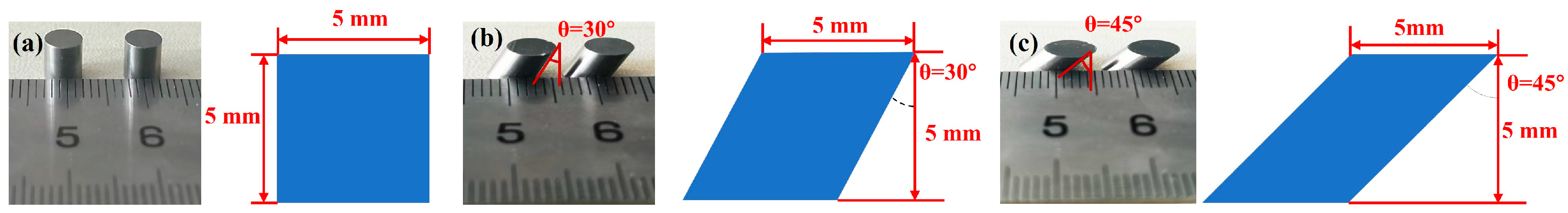
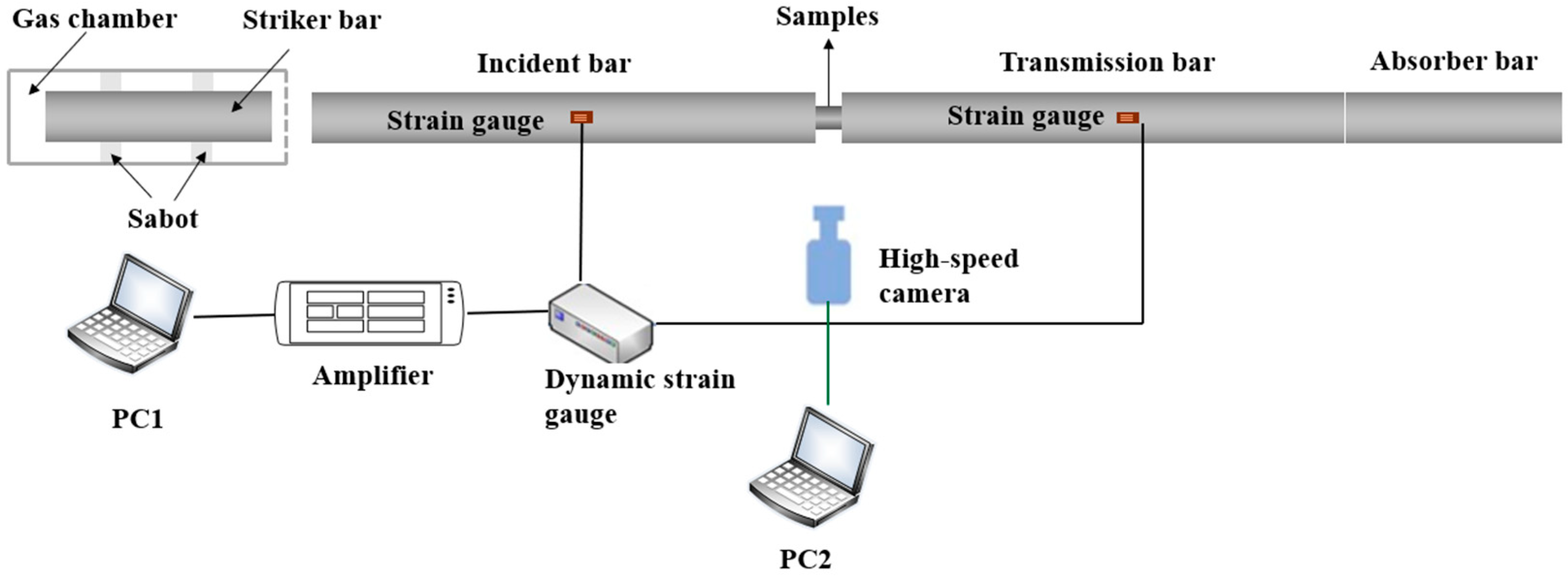
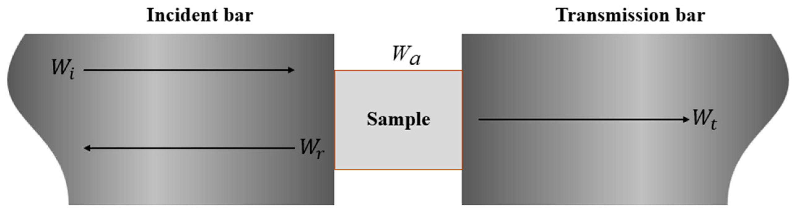
2.3. Mechanical Property Testing Methods

To obtain the dynamic mechanical properties of the WMoZrNiFe energetic structural material under medium-to-high-strain-rate conditions (10~104 s−1), dynamic compression experiments were conducted using the split-Hopkinson pressure bar (SHPB) apparatus. The dynamic compression samples were cylindrical with a diameter of 5 mm and a length of 5 mm, as shown in Figure 2. In dynamic compression experiments, due to different inclination angles, the specimen is under different compression-shear stress conditions. On the condition of three representative inclination angles (0°, 30°, and 45°), the dynamic mechanical response and the ignition threshold of WMoZrNiFe energetic structural material could be obtained.
The SHPB apparatus consisted of a high-pressure gas chamber, strike bar, incident bar, transmission bar, and energy absorption device. The dimensions of the striker bar were Φ14 mm × 200 mm, the incident bar was Φ14 mm × 1200 mm, and the transmission bar was Φ14 mm × 1200 mm, with all bars being made from high-strength steel (elastic modulus: 190 GPa, density: 7800 kg/m3, wave velocity: 4900 m/s). The strike bar velocity was adjusted through pressure modulation in the gas reservoir, enabling controlled energy input into the test specimen.
A high-speed camera (Fastcam Nova S16, frequency: 150,000 frames persecond, Manufacturer: Photron, Place of Origin: Tokyo, Japan) was used to capture the material’s dynamic deformation and fracture process. During the experiment, striker bar driven by high-pressure gas struck the incident bar, generating an elastic wave. This elastic wave then propagated through the sample placed between the incident and transmission bars, causing both reflection and transmission. Strain gauges were used to record the incident wave, reflected wave, and transmitted wave signals. The striker velocity of the bullet was adjusted by varying the pressure in the high-pressure gas chamber, enabling different strain rate loading conditions.
After the dynamic compression tests, the fracture morphology and elemental distribution were characterized using scanning electron microscopy (SEM, model: Thermo Scientific Apreo 2 SEM, Manufacturer: Thermo Fisher, Place of Origin: Hessen, Germany).

3. Experimental Results and Analysis

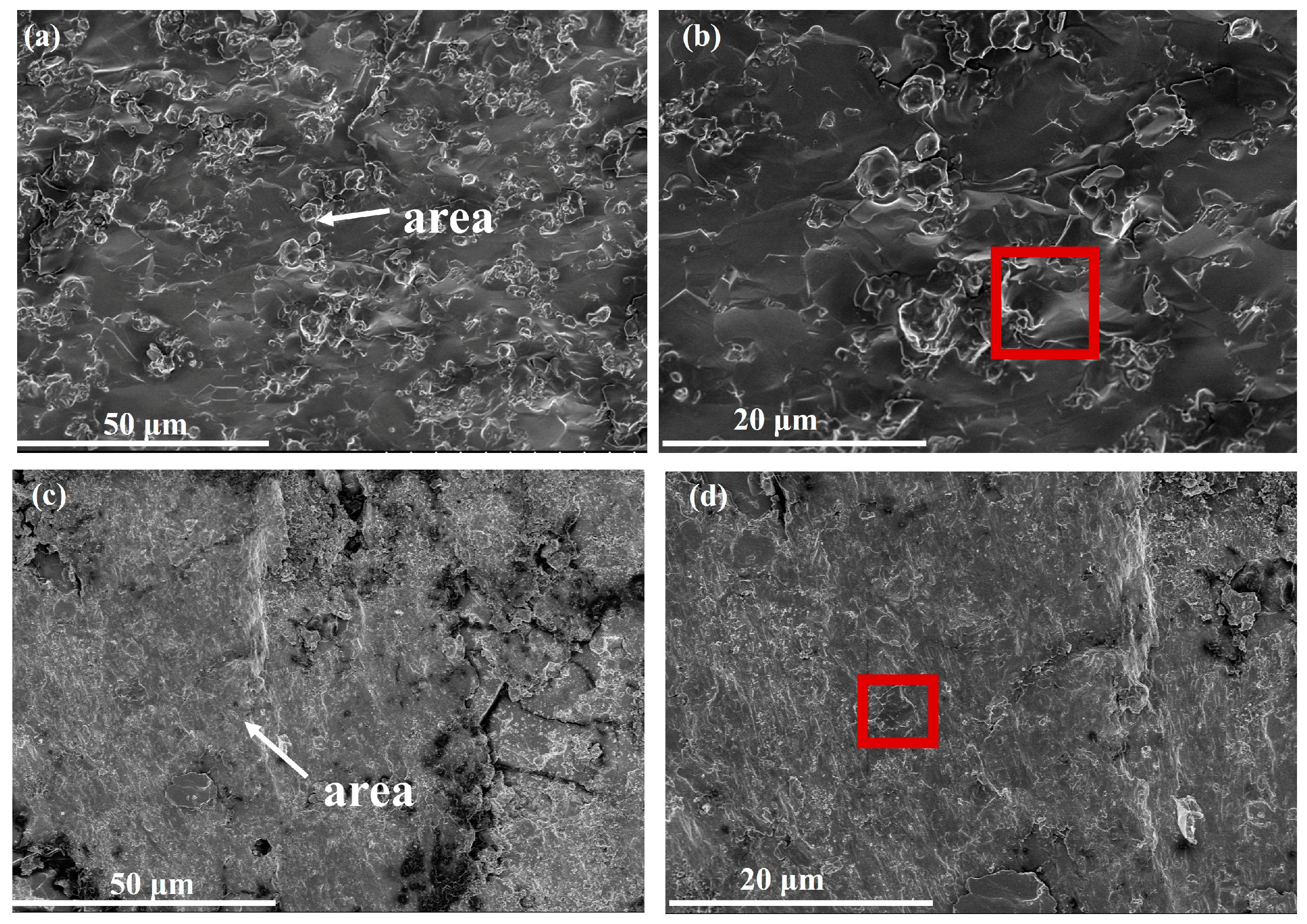
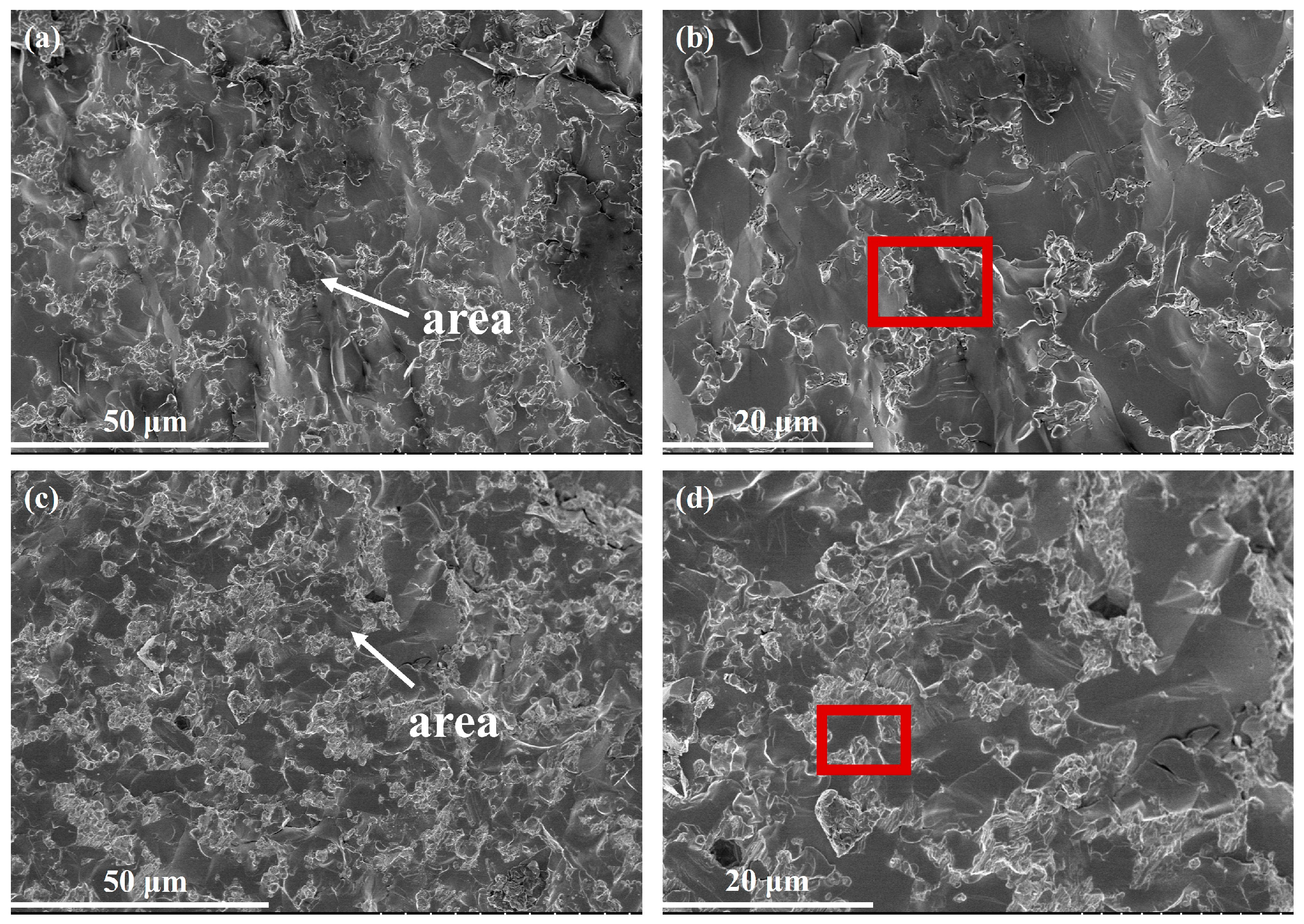
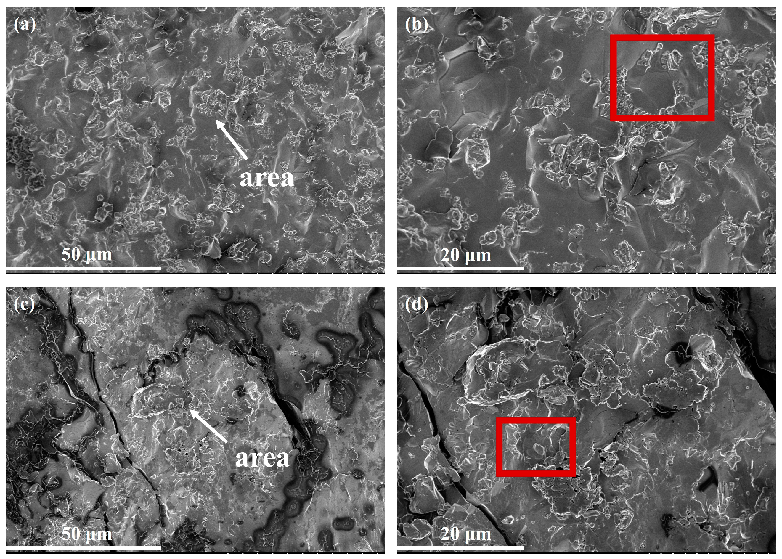
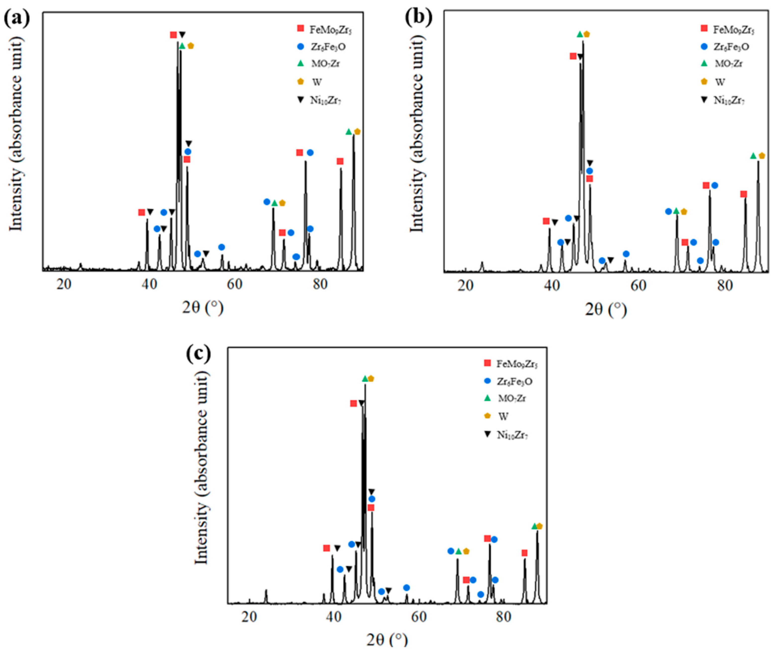
3.1. Microstructure Characteristics

Figure 3a shows the SEM image of the WMoZrNiFe energetic structural material, along with the EDS elemental mapping results. Figure 3b presents the XRD phase distribution of the WMoZrNiFe energetic structural material after sintering. As shown in Figure 3a, the EDS elemental distribution results indicate the occurrence of element segregation. Specifically, W, Mo, and Zr are enriched, while Fe and Ni are more evenly dispersed. In Figure 3b, the XRD phase distribution reveals that after sintering the WMoZrNiFe, an alloy structure is formed.

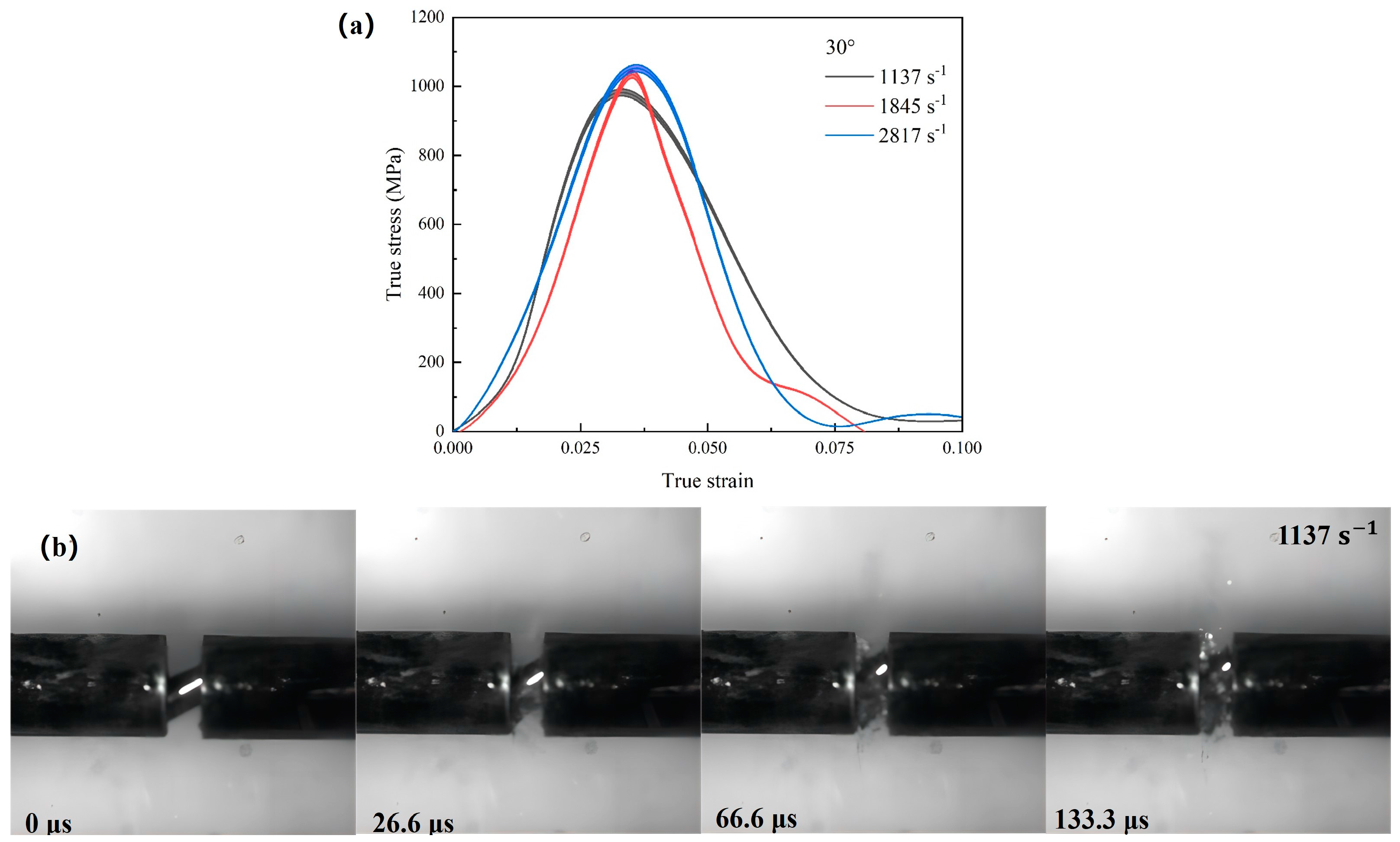
3.2. Mechanical Properties

Figure 4, Figure 5 and Figure 6 present the true stress–true strain curves and deformation failure processes for the WMoZrNiFe energetic structural materials at 0°, 30°, and 45°. Figure 4b, Figure 5b and Figure 6b demonstrate that the WMoZrNiFe energetic structural materials exhibit high compressive strength and strain rate effects. For the 0° sample, as the strain rate increased from 1753 s−1 to 2998 s−1, the compressive strength increased from 1468 MPa to 1837 MPa. For the 30° sample, when the strain rate increased from 1137 s−1 to 2817 s−1, the compressive strength increased from 982 MPa to 1053 MPa. For the 45° sample, as the strain rate increased from 1050 s−1 to 2715 s−1, the compressive strength increased from 420 MPa to 812 MPa. Obviously, as the inclination angle increased, it was much easier for the specimen to fracture. The dynamic response of the shear-dominated deformation mechanism governed the plastic flow. Further, it enhanced accumulation of plastic deformation and consequently led to an elevated failure strain.
Figure 4b, Figure 5b and Figure 6b illustrate the deformation and failure evolution of the WMoZrNiFe energetic structural materials under dynamic compression. All three samples exhibited the same fracture type, characterized by axial splitting. A comparison of the fracture strength for the three different inclination angles at similar strain rates revealed that the sample’s inclination angle significantly influenced its fracture strength. Within the 0° to 45° range, the greater the inclination angle, the lower the corresponding fracture strength.
To further analyze the failure mechanism of the WMoZrNiFe energetic structural material under dynamic compression, the fracture morphology was observed using SEM. Figure 7, Figure 8 and Figure 9 show the fracture morphologies of the 0°, 30°, and 45° WMoZrNiFe energetic structural materials under dynamic compression at different strain rates (with the area representing the region observed under higher magnification).
The fracture surfaces reveal the presence of stepped morphologies and ductile dimple regions (highlighted by red boxes), indicating a mixed mode of ductile-brittle fracture. The fracture surface of the energetic structural material also exhibits large molten regions, which are attributed to the energy release reactions that occur after the material fractures. The surface temperature increases during this process, resulting in the formation of molten areas.
Figure 10a–c show the elemental composition of the fracture surfaces of 0°, 30°, and 45° WMoZrNiFe energetic structural materials under dynamic compression at different strain rates. It can be observed that oxygen (O) is present in the fracture surfaces of the samples tested at both low and high strain rates, confirming that the energetic structural material primarily experiences reactions between its active elements and oxygen from the air under dynamic loading, releasing energy.
For the 0° WMoZrNiFe sample, when the strain rate increases from 1753 s−1 to 2998 s−1, the atomic percentage of O increases from 17.65% to 39.17%. For the 30° WMoZrNiFe sample, when the strain rate increases from 1137 s−1 to 2817 s−1, the atomic percentage of O increases from 13.85% to 24.90%. For the 45° WMoZrNiFe sample, when the strain rate increases from 1050 s−1 to 2715 s−1, the atomic percentage of O increases from 14.11% to 20.73%. This indicates that as the strain rate increases, the reaction between the active elements in the energetic structural material and oxygen from the air becomes more intense, increasing the oxygen content in the reaction products.
In comparison to the unreacted WMoZrNiFe energetic structural material, the W content in the reaction products significantly decreases, and the Mo content also decreases. The Zr content increases relatively due to the consumption of the reactive elements, which decreases their content. For dynamic compression experiments conducted at similar strain rates, the 0° WMoZrNiFe sample exhibited a higher oxygen content in its fracture surface compared to the 30° and 45° samples. This indicates that the 0° WMoZrNiFe sample undergoes a more significant reaction with oxygen from the air than the 30° and 45° samples.
Figure 11 presents XRD analysis results of recovered residues after dynamic compression experiments at three inclination angles. Under dynamic compression conditions, the energy release mechanism of WMoZrNiFe energetic structural materials was governed by synergistic intermetallic reactions and oxidation processes, yielding oxide phases Zr6Fe3O along with intermetallic compounds FeMo9Zr5, Mo7Zr, and Ni10Zr7. The XRD patterns and EDS analysis proved the ignition mechanism of this material system. From Figure 4, Figure 5 and Figure 6, the material initially undergoes fragmentation, during which frictional interactions generate localized hot spots that induce the intermetallic reaction. This thermal feedback triggers sequential oxidation reactions under elevated temperature conditions, releasing substantial thermal energy through exothermic chemical processes.

4. Dynamic Ignition Behavior

Based on the SHPB and high-speed camera dynamic testing system, high-speed photographic images were used to determine whether ignition occurred during the first pulse loading process. The high-speed camera records images starting from the zero point determined by the onset of material deformation, primarily to observe the deformation process and ignition conditions. The ignition threshold of the WMoZrNiFe energetic structural material was tested using the up–down method: if ignition occurred at a certain strain rate, the strain rate was lowered in the next test; if ignition did not occur, the strain rate was increased for the subsequent test. The adjustment of the strain rate was controlled by the air pressure in the SHPB device’s high-pressure chamber. Due to the limitations of the SHPB device, when the air pressure was lower than 0.03 MPa, no failure occurred in the WMoZrNiFe material, and 0.03 MPa was considered to be the ignition threshold for both the 30° and 45° samples.
Figure 12 presents the high-speed photographic images of the ignition process of the 0°, 30°, and 45° WMoZrNiFe energetic structural materials under different strain rates. As shown in Figure 11a, at a strain rate of 1753 s−1, the 0° sample did not show ignition but underwent compression and fracture, with shattered particle splashing. At a strain rate of 2567 s−1, ignition occurred at around 253 μs, triggering the overall combustion of the WMoZrNiFe material, and the reaction concluded at approximately 7100 μs, lasting for 6847 μs. At a strain rate of 2998 s−1, ignition occurred at around 100 μs, leading to intense combustion, and the reaction ended at approximately 18,000 μs, with an ignition duration of 17,900 μs.
As shown in Figure 12b, at a strain rate of 1137 s−1, the 30° sample did not ignite, although some particles exhibited flashes in the air. At 2445 s−1, ignition occurred at 167 μs, and combustion continued until approximately 12,745 μs, with a duration of 12,578 μs. At 2817 s−1, ignition occurred at 107 μs, followed by intense combustion, and the reaction finished at 15,692 μs, lasting for 15,585 μs.
Similarly, in Figure 12c, at a strain rate of 1050 s−1, the 45° sample showed no overall ignition, with only a few particles igniting, causing flashes. At 1770 s−1, ignition occurred at 267 μs, and the reaction lasted until 12,328 μs, with ignition lasting 12,061 μs. At 2715 s−1, ignition occurred at 200 μs, leading to intense combustion, and the reaction ended at 13,333 μs, lasting 13,133 μs.
As the loading strain rate increased, the ignition delay time decreased, and the ignition duration increased for the 0°, 30°, and 45° samples. This was due to the intense friction occurring during dynamic compression at higher strain rates, which shortened the ignition delay and prolonged the ignition duration. Furthermore, comparing the combustion behavior at the same time point for different strain rates revealed that higher strain rates resulted in more intense ignition reactions, with more violent combustion of the WMoZrNiFe material.
In the SHPB experiment, the WMoZrNiFe material samples were subjected to dynamic impact, causing fracture and the formation of fractured particles. These particles came into full contact with atmospheric oxygen. Due to the dynamic fracture, energy dissipation occurred, and the local temperature increased, leading to the reaction of the elements with oxygen and the release of energy, thereby triggering ignition. It is noteworthy that this material has low plastic deformation, which helps it to break apart more effectively under dynamic loading, promoting the energy release reactions needed for damage effects [16,17,18].
The energy absorbed by the sample during the compression process, W a , based on the SHPB experimental principle, is calculated as follows:
W a = W i W r W t
In the equation, W i , W r , and W t represent the energies of the incident wave, reflected wave, and transmitted wave, respectively. The energy transfer process is schematically illustrated in Figure 13. The absorbed energy W a is primarily consumed for specimen fragmentation and ignition.
According to [19], energy dissipation during the SHPB, loading process mainly involves the energy required for fracture and the kinetic energy of the broken particles. Among them, the kinetic energy accounts for a small proportion of the total energy dissipation, so the kinetic energy after the specimen’s impact fracture can be ignored. Based on the one-dimensional elastic stress wave theory and the uniformity assumption, the energy carried by the elastic wave in the rod can be expressed as
W i = A E c 0 t ε i 2 t d t
W r = A E c 0 t ε r 2 t d t
W t = A E c 0 t ε t 2 t d t
In the equation, A is the cross-sectional area of the input and output rods, E is the elastic modulus of the input and output rods, c is the propagation speed of the stress wave in the rods, εi(t) and εr(t) are the incident wave and reflected wave signals in the specimen.
Figure 14 shows the curve of absorbed energy of the 0°, 30°, and 45° WMoZrNiFe energetic structural materials. As shown in Figure 14, from the perspective of absorbed energy -time characteristics, before 20 µs of loading, the energy absorption of the three samples remains nearly 0 J, indicating that the samples are in the elastic deformation stage with little energy absorption. Between 20 µs and 110 µs of loading time, the samples enter the plastic deformation stage, and energy absorption starts to increase as the samples undergo damage and fracture. At around 110 µs, the samples are essentially completely fractured, and the energy absorption stabilizes. For the 0° WMoZrNiFe energetic structural material, when the strain rate reaches 2567 s−1, the energy absorption reaches 7.78 J, and ignition occurs under the threshold condition. For the 30° and 45° WMoZrNiFe energetic structural materials, ignition occurs with only 2.96 J and 2.23 J of absorbed energy. From the perspective of absorbed energy-strain characteristics, the specimen undergoes deformation through energy absorption. As strain increases, the material progressively enhances its energy absorption capacity until fracture occurs. This indicates that the inclination angle of the specimen has a significant impact on the minimum absorption energy required for ignition. As the inclination angle increases, the minimum absorption energy required for ignition decreases. It is because as the inclination angle increases, the specimen is obviously in compression-shear stress, which easily induces the dynamic fracture. It means that the compression-shear stress strengthens plastic flow in localized regions, and furthermore mechanical energy is converted into thermal energy through plastic deformation. Finally, the ignition occurs.

5. Conclusions

In this study, WMoZrNiFe energetic structural materials were designed and fabricated. The microstructure, dynamic mechanical properties, and impact ignition behavior of these materials were systematically investigated, and the ignition reaction mechanism under dynamic compression was obtained. The specific conclusions are as follows:
(1)
The WMoZrNiFe energetic structural materials exhibit a certain strain rate effect. As the strain rate increases, the yield strength of the 0° material increases from 1468 MPa to 1837 MPa, the yield strength of the 30° material increases from 982 MPa to 1053 MPa, and the yield strength of the 45° material increases from 420 MPa to 812 MPa. The material exhibits higher critical failure strain and compressive strength. Moreover, at similar strain rates, increasing the inclination angle of the sample results in a decrease in fracture strength.
(2)
The excellent mechanical properties of WMoZrNiFe energetic structural materials are related to their microstructure. At higher strain rates, the fracture morphology of the sample is characterized by partial step-like features and ductile dimples, indicating a ductile–brittle mixed fracture mode.
(3)
In dynamic compression experiments, the main elements involved in the reaction with oxygen in the air are W and Mo. For dynamic compression experiments at similar strain rates, the reaction degree between the 0° WMoZrNiFe energetic structural material and oxygen in the air is higher than those of the 30° and 45° materials.
(4)
The energy absorption thresholds for the 0°, 30°, and 45° samples are 7.78 J, 2.96 J, and 2.23 J, respectively. The energy threshold decreases as the inclination angle increases, with the 45° sample having the lowest ignition threshold, making it more prone to ignition.

Author Contributions

Conceptualization, G.P.; methodology, G.P. and X.B.; software, Z.P. and R.L.; validation, Q.J. and J.N.; formal analysis, G.P., Z.P. and R.L.; investigation, Z.P.; resources, G.P. and R.L.; data curation, Z.P. and R.L.; writing—original draft preparation, G.P., Z.P., X.B. and Q.J.; writing—review and editing, R.L. and J.N.; visualization, R.L.; supervision, J.N.; project administration, X.B. and Q.J.; funding acquisition, J.N. All authors have read and agreed to the published version of the manuscript.

Funding

This study was supported by the National Natural Science Foundation of China (Grant No. 12272051).

Data Availability Statement

The original contributions presented in this study are included in the article, further inquiries can be directed to the corresponding author.

Conflicts of Interest

Author Xiaolu Bi was employed by the company Chongqing Hongyu Precision Industry Co., Ltd. The remaining authors declare that the research was conducted in the absence of any commercial or financial relationships that could be construed as a potential conflict of interest.

References

  1. Zheng, Z.; Jiang, X.; Zhao, J. Structural, electronic and elastic properties of several metal organic frameworks as a new kind of energetic materials. Chem. Phys. Lett. 2015, 628, 76–80. [Google Scholar] [CrossRef]
  2. Wang, M.; Qiu, L.; Zhao, X.; Li, Y.; Rao, T.; He, S.; Qin, L.; Tao, J. Multilayered Al/Ni energetic structural materials with high energy density and mechanical properties prepared by a facile approach of electrodeposition and hot pressin. Mater. Sci. Eng. A 2019, 757, 23–31. [Google Scholar] [CrossRef]
  3. Semin, V.O.; Yamada, R.; Hamasaki, Y.; Miyajima, Y.; Ishikawa, K.; Watanabe, A.; Kwon, H.; Kim, H.; Kato, H.; Louzguine-Luzgin, D. The effect of some late 3d transition metals additions to a Fe-Mn-Al-C alloy on the development of high-entropy alloys. Intermetallics 2025, 177, 108589. [Google Scholar] [CrossRef]
  4. Millar, D.I.; Marshall, W.G.; Oswald, I.D.; Pulham, C.R. High-pressure structural studies of energetic materials. Crystallogr. Rev. 2010, 16, 115–132. [Google Scholar] [CrossRef]
  5. Hu, Q.; Liu, R.; Zhou, Q.; Geng, H.; Ge, C.; Wang, H.; Xiao, C.; Chen, P. Characterization of Ta-Ni-Al energetic structural material fabricated by explosive consolidation. J. Alloys Compd. 2022, 924, 166191. [Google Scholar] [CrossRef]
  6. Huang, C. Research on Prepartion, Mechanical and Thermal Characteristics of Metallic Energetic Structural Materials. Ph.D. Thesis, National University of Defense Technology, Changsha, China, 2020. (In Chinese). [Google Scholar]
  7. Tao, Y.; Bai, S.X.; Yang, S.; Li, S. Research status of preparation technology for reactive material structures. Chin. J. Nonferrous Met. 2017, 27, 2079–2090. (In Chinese) [Google Scholar]
  8. Zhao, P.; Lu, F.; Li, J.; Chen, R.; Xu, S.; Yang, S. The Dynamic Compressive Properties of PTFE/Al Reactive Materials. Energetic Mater. 2009, 17, 4. [Google Scholar]
  9. Ren, K.; Chen, R.; Lin, Y.; Li, S.; Zhang, X.; Dong, J. Probing the Impact Energy Release Behavior of Al/Ni-Based Reactive Metals with Experimental and Numerical Methods. Metals 2019, 9, 499. [Google Scholar] [CrossRef]
  10. Wang, B.; Fu, A.; Huang, X.; Liu, B.; Liu, Y.; Li, Z.; Zan, X. Mechanical Properties and Microstructure of the CoCrFeMnNi High Entropy Alloy Under High Strain Rate Compression. J. Mater. Eng. Perform. 2016, 25, 2985–2992. [Google Scholar] [CrossRef]
  11. Chen, H.; Zhang, X.; Xiong, W.; Liu, C.; Wei, H.; Wang, H.; Dai, L. Dynamic mechanical behavior and penetration performance of WFeNiMo high-entropy alloy. Chin. J. Theor. Appl. Mech. 2020, 52, 1443–1453. (In Chinese) [Google Scholar]
  12. Hou, X.; Xiong, W.; Chen, H.; Zhang, X.; Wang, H.; Dai, L. Impact energy release and damage characteristics of two high-entropy alloys. Chin. J. Theor. Appl. Mech. 2021, 53, 2528–2540. (In Chinese) [Google Scholar]
  13. Ren, H.; Li, W.; Ning, J.; Liu, Y. The Influence of Initial Defects on Impact Ignition of Aluminum/Polytetrafluoroethylene Reactive Material. Adv. Eng. Mater. 2020, 22, 1900821. [Google Scholar] [CrossRef]
  14. Ren, H.; Li, W.; Ning, J. Effect of temperature on the impact ignition behavior of the aluminum/polytetrafluoroethylene reactive material under multiple pulse loading. Mater. Des. 2020, 189, 108522. [Google Scholar] [CrossRef]
  15. Guo, Y.; Liu, R.; Ran, C.; Arab, A.; Geng, H.; Gao, M.; Guo, B.; Zhou, Q.; Chen, P. Ignition and energy release characteristics of energetic high-entropy alloy HfZrTiTa0.2Al0.8 under dynamic loading. J. Mater. Res. Technol. 2024, 28, 2819–2830. [Google Scholar] [CrossRef]
  16. Zhang, Z. Microstructure and Mechanical Properties of HfZrTiTax High-Entropy Alloys Energetic Structural Materials. Master’s Thesis, National University of Defense Technology, Changsha, China, 2017. (In Chinese). [Google Scholar]
  17. Ren, K.; Liu, H.; Chen, R.; Tang, Y.; Guo, B.; Li, S.; Wang, J.; Wang, R.; Lu, F. Compression properties and impact energy release characteristics of TiZrNbV high-entropy alloy. Mater. Sci. Eng. A 2021, 827, 142074. [Google Scholar] [CrossRef]
  18. Wang, R. Micro Structure Evolution and Energetic Structural Properties of NbZrTiTa High-Entropy Alloy. Master’s Thesis, National University of Defense Technology, Changsha, China, 2018. (In Chinese). [Google Scholar]
  19. Li, M.; Qiao, L.; Li, Q. Energy dissipation of rock specimens under high strain rate with single joint in SHPB tensile tests. Chin. J. Geotech. Eng. 2017, 39, 1336–1343. (In Chinese) [Google Scholar]
Figure 1. Samples at different inclination angles. (a) 0° samples (b) 30° samples (c) 45° samples.
Metals 15 00516 g001
Figure 2. An experimental schematic diagram of the SHPB.
Metals 15 00516 g002
Figure 3. Microstructure of WMoZrNiFe ESMs. (a) SEM image and EDS element surface scan (b) XRD phase distribution.
Metals 15 00516 g003
Figure 4. Mechanical properties of 0° WMoZrNiFe ESMs under different strain rates. (a) True stress-strain curves of 0° WMoZrNiFe ESMs. (b) High-speed photography images of 0° WMoZrNiFe ESMs under dynamic compression with 1753 s−1 strain rate.
Metals 15 00516 g004
Figure 5. Mechanical properties of 30° WMoZrNiFe ESMs under different strain rates. (a) True stress-strain curves of 30° WMoZrNiFe ESMs. (b) High-speed photography images of 30° WMoZrNiFe ESMs under dynamic compression with 1137 s−1 strain rate.
Metals 15 00516 g005
Figure 6. Mechanical properties of 45° WMoZrNiFe ESMs under different strain rates. (a) True stress-strain curves of 45° WMoZrNiFe ESMs. (b) High-speed photography images of 45° WMoZrNiFe ESMs under dynamic compression with 1050 s−1 strain rate.
Metals 15 00516 g006
Figure 7. Fracture morphology of 0° WMoZrNiFe ESMs under dynamic compression ((a,b) 1753 s−1 strain rate; (c,d) 2998 s−1 strain rate).
Metals 15 00516 g007
Figure 8. Fracture morphology of 30° WMoZrNiFe ESMs under dynamic compression ((a,b) 1137 s−1 strain rate; (c,d) 2817 s−1 strain rate).
Metals 15 00516 g008
Figure 9. Fracture morphology of 45° WMoZrNiFe ESMs under dynamic compression ((a,b) 1050 s−1 strain rate; (c,d) 2715 s−1 strain rate).
Metals 15 00516 g009
Figure 10. The content at the fracture surfaces of WMoZrNiFe ESMs under dynamic compression at different strain rates. (a) 0° WMoZrNiFe ESMs (b) 30° WMoZrNiFe ESMs (c) 45° WMoZrNiFe ESMs.
Metals 15 00516 g010
Figure 11. XRD analysis results of recovered residues from the WMoZrNiFe energetic structural material following dynamic compression experiments. (a) 0° WMoZrNiFe ESMs (b) 30° WMoZrNiFe ESMs (c) 45° WMoZrNiFe ESMs.
Metals 15 00516 g011
Figure 12. High-speed photographic images of WMoZrNiFe ESMs during impact ignition process at different strain rates. (a) High-speed photographic images of 0° WMoZrNiFe ESMs during impact ignition process. (b) High-speed photographic images of 30° WMoZrNiFe ESMs during impact ignition process. (c) High-speed photographic images of 45° WMoZrNiFe ESMs during impact ignition process.
Metals 15 00516 g012
Figure 13. Schematic diagram of energy transfer processes in SHPB experiments.
Metals 15 00516 g013
Figure 14. Absorbed energy-time curves and Absorbed energy-true curves of WMoZrNiFe ESMs. (a) 0° WMoZrNiFe ESMs (b) 30° WMoZrNiFe ESMs (c) 45° WMoZrNiFe ESMs.
Metals 15 00516 g014
Table 1. Particle sizes and purity of the single-element powder.
NamePurity (%)Particle Size (μm)
W powder≥99.991–5
Mo powder≥99.91–5
Zr powder≥991–5
Ni powder≥99.91–5
Fe powder≥99.91–5
Disclaimer/Publisher’s Note: The statements, opinions and data contained in all publications are solely those of the individual author(s) and contributor(s) and not of MDPI and/or the editor(s). MDPI and/or the editor(s) disclaim responsibility for any injury to people or property resulting from any ideas, methods, instructions or products referred to in the content.

