Article

Effect of Heat Treatment on the Corrosion Behavior of Selective Laser Melted CX Stainless Steel

1
School of Navigation and Shipping, Shandong Jiaotong University, Weihai 264209, China
2
School of Construction Machinery, Shandong Jiaotong University, Jinan 250357, China
3
Merchant Marine College, Shanghai Maritime University, Shanghai 201306, China
4
Shanghai Nanotechnology and Industry Development Promotion Center, Shanghai 200237, China
*
Author to whom correspondence should be addressed.
Metals 2025, 15(5), 517; https://doi.org/10.3390/met15050517
Submission received: 6 April 2025 / Revised: 28 April 2025 / Accepted: 2 May 2025 / Published: 3 May 2025

Abstract

The effects of different heat treatment regimes on the microstructure and corrosion behavior of selectively laser melted (SLM) Corrax (CX) stainless steel were systematically investigated. Three distinct thermal processing approaches solution treatment (ST), aging treatment (AT), and combined solution aging treatment (ST + AT) were comparatively examined to assess their microstructural evolution and corrosion performance. The results demonstrated that the SLM-processed CX sample initially consisted of martensite and retained austenite. After solution treatment at 900 °C for 0.5 h, microsegregation was eliminated, and the retained austenite fully transformed into martensite. During direct aging at 525 °C for 3 h (AT), a portion of the martensite reverted to austenite, accompanied by grain refinement that reduced the average grain size to 1.79 μm. When the CX was solution-aged at 900 °C for 0.5 h and then 525 °C for 4 h (ST + AT), the retained austenite transformed completely into martensite. The results of potentiodynamic polarization measurements and electrochemical impedance spectroscopy (EIS) revealed that the aged specimen demonstrated comparatively superior corrosion resistance with reduced surface accumulation of corrosion products relative to both ST and ST + AT specimens. The electrochemical test results indicate that the selection of heat treatment parameters has a significant impact on the corrosion resistance of SLM-formed CX samples. Compared to ST and ST + AT, the corrosion performance of AT-treated samples is improved to a certain extent, with the highest Epit (322 mV) and the largest ΔE (742). The corrosion potential is relatively high (Ecorr, −414 mV vs. SCE), and the corrosion current density is relatively low (Icorr, 0.405 μA·cm−2). This indicates that the AT samples exhibit good corrosion resistance.

1. Introduction

Selective Laser Melting, as an additive manufacturing (AM) technology, enables the fabrication of geometrically complex metallic components with enhanced design flexibility and superior material utilization efficiency [1,2]. However, the material undergoes continuous rapid melting and solidification cycles during the SLM process, which inevitably generates defects (e.g., pores and inclusions) and substantial residual stresses [3]. These defects not only compromise mechanical properties such as fatigue resistance and ductility but also severely degrade the corrosion resistance of SLM-fabricated components [4]. To mitigate these limitations, heat treatment has been widely adopted as a post-processing method.
Corrax stainless steel is a novel martensitic precipitation-hardening stainless steel that has attracted considerable attention from researchers due to its excellent strength [5]. The CX stainless steel components fabricated via SLM demonstrate an exceptional microstructure, featuring high-density dislocations and nanoscale precipitates within the martensitic matrix [6], demonstrating remarkable mechanical properties with an ultimate tensile strength (UTS) of 1058 MPa and impact toughness of 57.7 J [7]. Recent studies have explored how processing parameters and microstructures influence the corrosion behavior of stainless steel fabricated via selective laser melting (SLM). Sun et al. [8] investigated the effect of processing parameters on the corrosion resistance of SLM-produced 316L stainless steel in 0.9 wt% NaCl. They demonstrated that samples fabricated with a laser power of 150 W and a scanning speed of 0.15 m/s exhibited minimal porosity and optimal corrosion resistance. Asgari et al. [9] reported that SLM-produced CX stainless steel displayed exceptional mechanical properties, including an ultimate tensile strength of 1113 MPa and an elongation of 21.7%. Schaller et al. [10] observed reduced corrosion resistance in SLM-processed 17-4PH stainless steel immersed in 0.6 M NaCl, attributing this to the presence of numerous lack-of-fusion pores. Man et al. [11] demonstrated that selective laser melted (SLM) 316L stainless steel develops a thicker passive surface layer than conventionally forged material, a characteristic directly linked to the higher dislocation density and grain boundary concentration generated during the additive manufacturing process. Jia et al. [12] prepared CX stainless steel samples using SLM, observing a matrix dominated by martensite with minimal austenite. The fine-grained structure and precipitated phases provided good mechanical properties, although the high dislocation density adversely affected corrosion resistance. Zhao et al. [13] investigated the heterogeneous microstructure of high strength, aging martensitic stainless steel formed by SLM, observing the presence of NiAl precipitates and alumina inclusions. The sample exhibited an ultimate tensile strength of 1647 MPa and a microhardness of 520 HV. Currently, research on how heat treatment parameters influence the corrosion behavior of SLM CX stainless steel is still incomplete. Few systematic studies have been reported on the interaction between post-processing conditions and microstructure evolution.
Building on these insights, this study investigates the effects of heat treatment process parameters on the corrosion behavior and microstructure of SLM-fabricated CX stainless steel and further explores the potential corrosion mechanisms, aimed at providing theoretical support and data accumulation for practical applications.

2. Experimental Conditions

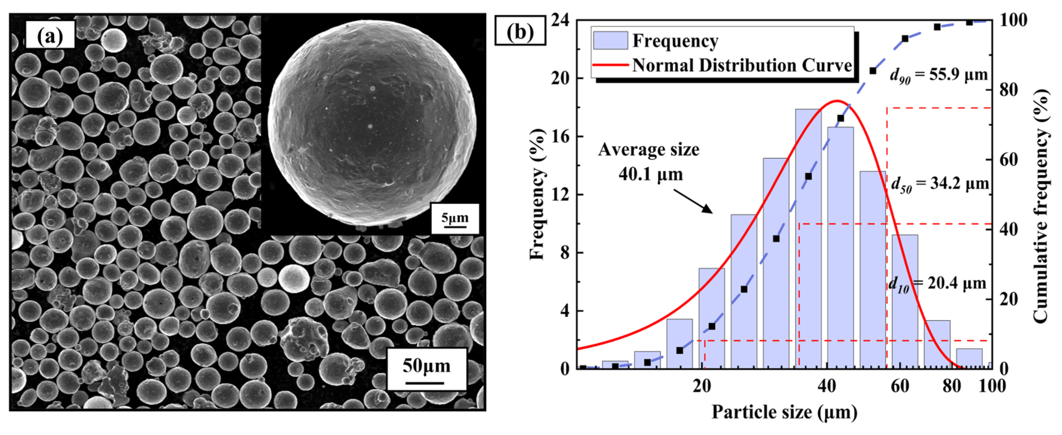
2.1. Experimental Materials

The raw material used in this experiment is the gas-atomized CX stainless steel alloy powder produced by Vlory, and the main chemical composition of the alloy is shown in Table 1. Figure 1a shows the micro morphology of the powder particles. It can be seen that the alloy powder is mainly spherical with a smooth surface and good flowability. Figure 1b shows the particle size distribution of the powder. It can be observed that the particle size conforms to a normal distribution, indicating that the powder meets the requirements for SLM forming. The experiments used a 304 stainless steel substrate with a diameter of 150 mm and a height of 25 mm. Before manufacturing, the substrate must undergo mechanical polishing to ensure the surface roughness (Ra) is below 1.6 μm. This smoothness minimizes localized stress concentrations, enhances interlayer adhesion, and prevents defects such as delamination or warpage caused by uneven thermal contraction. Additionally, the substrate should be preheated to 65 ± 5 °C to reduce residual stresses caused by rapid solidification and improve the relative density of the fabricated part [14].

2.2. Preparation Process

The CX metallographic specimens with dimensions of 10 mm × 10 mm × 10 mm were fabricated using selective laser melting (SLM). The specimens underwent three heat treatment regimes: ST (850 °C/0.5 h), AT (525 °C/4 h), and ST + AT. The SLM process utilized high-purity argon as a protective gas to establish a gas-sealed chamber, maintaining oxygen content below 500 ppm, with a laser power of 200 W and a scanning speed of 900 mm/s. All specimens were heat-treated in a box-type high-temperature sintering furnace (HF-Kejing, China; Model SX2-10-13) with a controlled heating rate of 5 °C/min. Following heat treatment, the microstructural characterization of all SLM-processed specimens was conducted on planes parallel to the build direction.

2.3. Test Methods

The test samples were sequentially polished using sandpaper with grit sizes ranging from 240 to 2000 on an automatic polishing machine, with a rotational speed of 400 r/min and a single-point pressure of 15 N. Subsequently, a 0.5 μm diamond polishing slurry was used on a velvet polishing cloth for coarse polishing, followed by a 0.05 μm SiO2 suspension on a nylon polishing cloth for fine polishing until the surface became smooth and free of scratches. Samples need to be electropolished before ESBD testing to observe their microstructure morphology. Electropolishing is performed using a solution consisting of 10% perchloric acid and 90% acetic acid to remove residual surface stress. The corrosion parameters are set as follows: voltage of 20 V, current of 0.3 A, and corrosion time of 45 s. Notably, perchloric acid must be handled in fume hoods with adequate ventilation, away from heat sources. Appropriate protective equipment is required when preparing or employing perchloric acid-containing solutions [15]. Phase analysis was conducted using a Bruker D8 Advance X-ray diffractometer (XRD), the scans ranged from 20° to 100° and the scanning speed was 5°/min. The microstructure of the specimen was observed using an Electron Backscatter Diffraction System (EBSD) produced by Oxford Instruments UK, model Nordly Max3.. Electrochemical tests were conducted on an electrochemical workstation produced by Metrohm Autolab in the Netherlands, model PGSTAT 302N. In this system, CX samples with an exposed area of 0.5 cm2 are used as working electrodes, with a saturated calomel electrode (SCE) and a graphite rod serving as the reference and auxiliary electrodes, respectively. Specimens were immersed in electrolytes for 30 min to stabilize open circuit potential before testing. The high surface activity of polished stainless steel necessitates a 20~30 min transition period in electrolyte, progressing from initial oxide film formation to complete passive layer development [16]. Potentiodynamic polarization measurements were conducted at a scan rate of 1 mV/s, with electrochemical impedance spectroscopy (EIS) tests performed over a frequency range of 0.01 Hz to 100 kHz. All electrochemical evaluations were implemented in 3.5 wt% NaCl solution at room temperature, with triplicate tests performed to ensure data reproducibility. Post-corrosion surface morphologies of CX specimens were characterized using a Zeiss Sigma 300 field-emission scanning electron microscope (SEM) produced by the German Carl Zeiss Group.

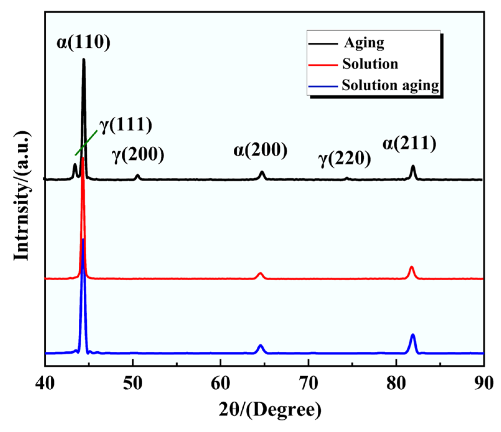
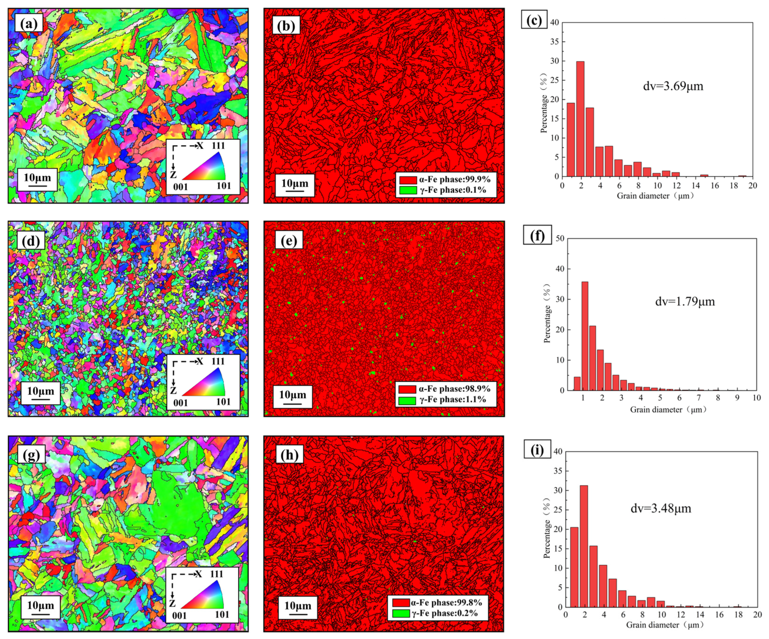
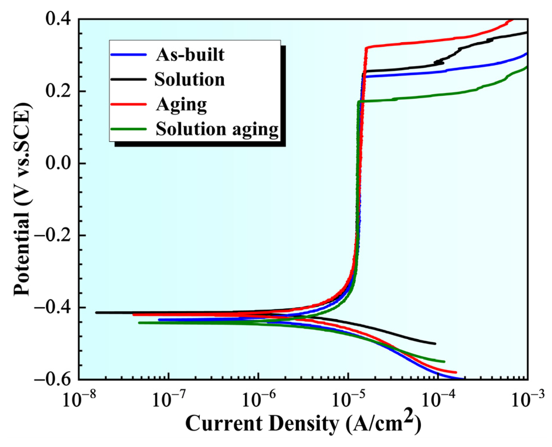
3. Results and Discussions

Figure 2 shows the inverse pole figure (IPF) and corresponding orientation color code of the SLM-fabricated CX sample, in which the grain orientations of <111>, <001>, and <101> crystal orientations are marked in blue, red, and green, respectively. The high scanning speed, rapid cooling rate, and short heating time characteristics of the SLM process resulted in a fine-grained microstructure. Additionally, the weak texture indicates no significant preferred orientation in grain distribution. Simultaneously, small substructures with distinct orientations relative to the large grains were observed within coarse grains. These substructures formed through dislocation entanglement and closure [17,18]. As shown in Figure 2b, the deposit state sample is primarily composed of martensite and residual austenite, with martensite being the dominant phase, accounting for approximately 99.6%. Moreover, the grain size of the deposit state sample is very small, with an average grain size (dv) of about 1.43 μm. Research indicates that smaller grain sizes result in more active atoms at grain boundaries, which enhances the passivation layer [19,20].
Figure 3 presents the XRD patterns of the heat-treated samples. The phase composition varied significantly across different heat treatment conditions. Following solution treatment (ST), the α-phase (110) peak intensity increased markedly, while the γ-phase (111), (200), and (220) peaks disappeared entirely. This indicates that the ST process facilitated the complete transformation of retained γ-phase into α-phase, with preferential growth along the (110) crystallographic orientation [21]. In contrast, direct aging treatment (AT) resulted in enhanced intensity of the γ-phase (111), (200), and (220) peaks. This suggests that the aging treatment promoted the reversion of martensite to austenite, thereby increasing the austenite content. Notably, no detectable γ-phase peaks were observed in the ST + AT specimens, confirming the complete transformation of austenite to martensite without retained or reverted austenite [22].
A comparative analysis of Figure 4a,d,g reveals that all heat-treated specimens contained martensite, but they displayed distinct morphological characteristics depending on thermal processing parameters. Solution treatment promoted the formation of coarse lath-like martensite through residual austenite transformation. After ST + AT, the original austenite grain boundaries remain unchanged, and a new martensitic structure forms within the matrix, with its size slightly reduced. In contrast, direct aging generated refined blocky martensite with significantly increased grain boundary density. As evidenced by Figure 4c,f,i, the direct aging treatment achieved substantial grain refinement with an average grain size (dv) of 1.79 μm. Quantitative phase analysis based on Figure 4b,e,h shows that aged specimens contained approximately 1.1% retained austenite. Previous studies [23] suggest that although the FCC-structured austenite phase occupies a minor fraction, its chromium-enriched nature facilitates localized passivation-active regions at phase boundaries. This promotes preferential formation of dense Cr2O3 films that effectively inhibit chloride ion adsorption and selective dissolution in BCC α-phase matrix, particularly at high-density crystalline defect sites [24], this enhances the corrosion resistance of the specimen.
Figure 5 shows the potentiodynamic polarization curves of the heat treatment samples, which exhibit differences in shape and trend but all display typical passivation characteristics. The potentiodynamic polarization curves of these specimens can be broadly categorized into four distinct potential regions: active dissolution region, transition passivation region, stable passivation region, and overpassivation region. Notably, the passive layer demonstrates a protective effect on the SLM-formed CX samples, effectively inhibiting corrosion. Notably, compared to the as-built state, the stable passive region of the heat treatment samples is significantly enlarged, indicating enhanced stability of the passive film and reduced risk of corrosion [14]. Compared to other samples, the passive region of the solution treatment and aged samples is narrower, making the samples more prone to enter the overpassivation zone, resulting in decreased resistance to pitting corrosion. Table 2 lists the corrosion parameters of the samples. AT has the highest Epit (322 mV), but also the largest ΔE (742). Although aging treatment improves the resistance to pitting initiation, once pitting occurs, it spreads rapidly, leading to poor repair capability of the passive film. ST + AT has the lowest Epit (172 mV) and the smallest ΔE (614), indicating that its passive film can still inhibit pitting propagation after initiation, with better repair capability of the passive film. This is due to the more uniform distribution of precipitate phases in ST + AT, resulting in lower risks of localized microgalvanic corrosion [25,26]. Meanwhile, the average grain size (dv) of the aged sample is approximately 1.79 μm (as shown in Figure 4f). Additionally, it exhibits a high Ecorr (−414 mV) and low Icorr (0.405 μA-cm−2), indicating a relatively stable passive film and excellent resistance to uniform corrosion, but relatively poor resistance to pitting corrosion. This suggests that aging treatment enhances the substrate’s resistance to uniform corrosion but sacrifices its resistance to localized corrosion. ST + AT has the lowest Ecorr (−442 mV) and the highest Icorr (0.588 μA·cm−2), suggesting a slightly elevated matrix dissolution tendency, but due to the stable passive film, the risk of localized corrosion remains relatively low.
Figure 6 presents the electrochemical impedance spectroscopy (EIS) results for heat-treated samples under steady-state corrosion potential. As shown in Figure 6a, all heat-treated samples exhibit distinct capacitive arcs, suggesting a similar passivation mechanism. Prior studies indicate that larger capacitive arc diameters correlate with improved corrosion resistance [27]. Figure 6b,c display the Bode plots for the samples. In the high-frequency region of 1–104 Hz, the impedance spectra curves overlap; the |Z| exhibits a zero slope. In the low-frequency region (<0.1 Hz), the declining phase angle is linked to charge transfer processes, where corrosion resistance is dominated by the passive layer’s performance [28]. In contrast to other samples, the AT specimen exhibited a broader phase angle distribution, suggesting the formation of a highly stable passive layer. Figure 6d shows an equivalent circuit model with two time constants used to fit the EIS spectra of these samples. In the model, R1 represents the solution resistance, R2 represents the outer layer resistance, and R3 represents the inner layer charge transfer resistance. As shown in Table 3, the R3 values (inner layer resistance) significantly exceeded the R2 values (outer layer resistance) across all samples, indicating that corrosion resistance is predominantly controlled by the inner oxide layer. Among all tested samples, the aged sample exhibited a relatively high R3 value (248,000 Ω·cm2) and a low capacitance value (Q2 = 67.3 × 10⁶ F·cm−2), indicating that the passive layer formed on the aged sample at 530 °C demonstrates the most robust protective properties. These findings align with the polarization curve results.
Figure 7 shows the SEM image of the electrochemical corrosion surface. As illustrated in Figure 7f, corrosion pits of varying sizes are distinctly visible on the surface, confirming significant pitting behavior during the electrochemical corrosion process. Due to the accumulation of corrosion products, irregular nodular protrusions and elevated oxide layers can be observed in Figure 7a,d,g. To determine their composition, points P1 and P2 in Figure 7b were subjected to EDS analysis. The results are shown in Figure 8, indicating that the primary components at the measurement points include Fe, Cr, and C, among others. From this, it can be inferred that as corrosion progresses, dissolved metal ions undergo oxidation reactions, forming corrosion products such as Fe(OH)2 and Cr2O3 [29]. Figure 7c shows that the aged sample exhibits fewer corrosion products, a smoother surface, the most complete passive film, and better uniform corrosion resistance.

4. Conclusions

In summary, the aged samples exhibit the best corrosion resistance, with the highest Ecorr value (−414 mV SCE), the lowest Icorr value (0.405 μA·cm−2), and the maximum ΔE of 742 mV. Additionally, the Rf value is relatively high (248,000 Ω·cm2), and the capacitance value is relatively low (Q2 approximately 67.3 μF·cm−2), indicating that the protective effect of this passivation layer is the strongest. Furthermore, the passivation film of the aged specimens is more intact, with fewer corrosion products and a smoother surface, demonstrating excellent resistance to uniform corrosion. The characteristics of the passivation film and its corrosion resistance mechanism can support its long-term protective requirements in harsh environments, such as marine engineering and chemical equipment. Although this study reveals the effects of different heat treatments on the corrosion behavior of materials, certain limitations remain that require further investigation in subsequent work. The current experiments primarily focus on simulated 3.5% NaCl solution environments, while the complex multifactorial coupling effects in actual marine service conditions (e.g., temperature fluctuations, salinity gradients, and cyclic loading) have not been incorporated into the analysis. Future research should integrate real-world marine exposure tests with multiphysics-coupled simulations to more accurately evaluate the service performance degradation mechanisms of materials. Additionally, the potential influence of additive-manufactured materials’ anisotropy (e.g., build orientation and process parameters) on localized corrosion susceptibility still requires systematic investigation.

Author Contributions

Conceptualization, T.W. and J.H.; methodology, Y.Z.; software, Z.L.; validation, Y.L., T.W. and Y.Z.; formal analysis, S.W. (Shaoqian Wu); investigation, Z.L.; resources, S.W. (Shuo Wu); data curation, S.X.; writing—original draft preparation, S.W. (Shaoqian Wu); writing—review and editing, S.X. and S.W. (Shuo Wu); visualization, J.H.; supervision, Y.Z.; project administration, Y.L.; funding acquisition, S.W. (Shuo Wu). All authors have read and agreed to the published version of the manuscript. All authors have read and agreed to the published version of the manuscript.

Funding

This work was supported by the Shandong Province Key Research and Development Program—Research and industrialization of high-precision intelligent mine crusher, grant No. 2024TSGC0902. This research was also funded by the Shandong Jiaotong University discipline backbone research start-up fund. This research was also supported by the technology development project: Lightweight Intelligent Fast Boat Technology (2024370105122331).

Data Availability Statement

The datasets used and/or analyzed during the current study are available from the corresponding author on reasonable request.

Conflicts of Interest

The authors declare that they have no known competing financial interests or personal relationships that could have appeared to influence the work reported in this paper.

References

  1. Yang, Y.; Bai, Y.; Wang, Y.; Zhang, Y.; Weng, C.; Lu, W.F.; Wang, H. Compressive mechanical response and microstructures in low strain rate plastic deformation of stainless steel 316L fabricated by selective laser melting. J. Mater. Res. Technol. 2024, 29, 4327–4344. [Google Scholar] [CrossRef]
  2. Zhang, C.; Li, Z.; Zhang, J.; Tang, H.; Wang, H. Additive manufacturing of magnesium matrix composites: Comprehensive review of recent progress and research perspectives. J. Magnes. Alloys 2023, 11, 425–461. [Google Scholar] [CrossRef]
  3. Qi, X.; Gao, X.; Ma, C.; Huang, R.; Huang, F.; Liu, J.; Zhang, S. Effect of heat treatment on the intergranular corrosion of 316 L stainless steel fabricated by selective laser melting. Mater. Charact. 2025, 220, 114648. [Google Scholar] [CrossRef]
  4. Wei, J.; Wang, J.; Yang, J.; Zeng, Y.; Guan, Y. Effect of internal defects on the compression behavior of stainless steel lattice structure fabricated by selective laser melting. J. Manuf. Process. 2024, 120, 809–826. [Google Scholar] [CrossRef]
  5. Dineshraj, S.; Gupta, R.K.; Govind. Development, Post Processing and Characterization of Additive Manufactured Stainless Maraging Steel. Trans. Indian Inst. Met. 2024, 77, 3729–3738. [Google Scholar] [CrossRef]
  6. Yan, X.; Chen, C.; Chang, C.; Dong, D.; Zhao, R.; Jenkins, R.; Wang, J.; Ren, Z.; Liu, M.; Liao, H.; et al. Study of the microstructure and mechanical performance of C-X stainless steel processed by selective laser melting (SLM). Mater. Sci. Eng. A 2020, 781, 139227. [Google Scholar] [CrossRef]
  7. Zhang, J.; Wang, M.; Niu, L.; Liu, J.; Wang, J.; Liu, Y.; Shi, Z. Effect of process parameters and heat treatment on the properties of stainless steel CX fabricated by selective laser melting. J. Alloys Compd. 2021, 877, 160062. [Google Scholar] [CrossRef]
  8. Sun, Y.; Moroz, A.; Alrbaey, K. Sliding Wear Characteristics and Corrosion Behaviour of Selective Laser Melted 316L Stainless Steel. J. Mater. Eng. Perform. 2013, 23, 518–526. [Google Scholar] [CrossRef]
  9. Asgari, H.; Mohammadi, M. Microstructure and mechanical properties of stainless steel CX manufactured by Direct Metal Laser Sintering. Mater. Sci. Eng. A 2018, 709, 82–89. [Google Scholar] [CrossRef]
  10. Schaller, R.F.; Taylor, J.M.; Rodelas, J.; Schindelholz, E.J. Corrosion Properties of Powder Bed Fusion Additively Manufactured 17-4 PH Stainless Steel. Corrosion 2017, 73, 796–807. [Google Scholar] [CrossRef]
  11. Man, C.; Dong, C.; Liu, T.; Kong, D.; Wang, D.; Li, X. The enhancement of microstructure on the passive and pitting behaviors of selective laser melting 316L SS in simulated body fluid. Appl. Surf. Sci. 2019, 467–468, 193–205. [Google Scholar] [CrossRef]
  12. Zhao, X.; Jia, D.; Wei, S.; Gao, Y.; Liu, H. Investigation of tribo-corrosion behaviors of SLM-printed CX stainless steel under different loads. J. Mater. Res. Technol. 2024, 30, 5266–5277. [Google Scholar] [CrossRef]
  13. Zhao, X.; Zhao, K.; Gao, Y.; Wang, D. Influence of Microdefect on Mechanical Behaviors of CX Stainless Steel Produced by Selective Laser Melting. Met. Mater. Int. 2024, 31, 70–83. [Google Scholar] [CrossRef]
  14. Gao, P.; Jing, G.; Lan, X.; Li, S.; Zhou, Y.; Wang, Y.; Yang, H.; Wei, K.; Wang, Z. Effect of heat treatment on microstructure and mechanical properties of Fe–Cr–Ni–Co–Mo maraging stainless steel produced by selective laser melting. Mater. Sci. Eng. A 2021, 814, 141149. [Google Scholar] [CrossRef]
  15. Huang, C.A.; Lin, W.; Lin, S.C. The electrochemical polishing behaviour of P/M high-speed steel (ASP 23) in perchloric–acetic mixed acids. Corros. Sci. 2003, 45, 2627–2638. [Google Scholar] [CrossRef]
  16. Li, Z.; Qiu, C.; Liu, C.; Bai, Y.; Meng, H. The mechanoelectrochemical effect on the electrochemical corrosion of austenitic stainless steel. J. Mater. Res. Technol. 2023, 24, 1203–1215. [Google Scholar] [CrossRef]
  17. Mutua, J.; Nakata, S.; Onda, T.; Chen, Z.-C. Optimization of selective laser melting parameters and influence of post heat treatment on microstructure and mechanical properties of maraging steel. Mater. Des. 2018, 139, 486–497. [Google Scholar] [CrossRef]
  18. Li, J.; Jiang, W.; Zhang, Y.; Liu, L.; Yu, Y.; Luan, J.; Jiao, Z.; Liu, C.T.; Zhang, Z. Evolution and strengthening of nanoprecipitates in a high strength maraging stainless steel. Mater. Sci. Eng. A 2024, 915, 147198. [Google Scholar] [CrossRef]
  19. Bi, J.; Lei, Z.; Chen, Y.; Chen, X.; Lu, N.; Tian, Z.; Qin, X. An additively manufactured Al-14.1Mg-0.47Si-0.31Sc-0.17Zr alloy with high specific strength, good thermal stability and excellent corrosion resistance. J. Mater. Sci. Technol. 2021, 67, 23–35. [Google Scholar] [CrossRef]
  20. Ralston, K.D.; Birbilis, N.; Davies, C.H.J. Revealing the relationship between grain size and corrosion rate of metals. Scr. Mater. 2010, 63, 1201–1204. [Google Scholar] [CrossRef]
  21. Huang, J.; Zhang, D. Effect of heat treatment on precipitation behavior of second phase and property evolution of martensitic stainless steel. Mater. Today Commun. 2023, 37, 107267. [Google Scholar] [CrossRef]
  22. Pirgazi, H.; Sanjari, M.; Tamimi, S.; Shalchi Amirkhiz, B.; Kestens, L.A.I.; Mohammadi, M. Texture evolution in selective laser melted maraging stainless steel CX with martensitic transformation. J. Mater. Sci. 2020, 56, 844–853. [Google Scholar] [CrossRef]
  23. Dong, D.; Chang, C.; Wang, H.; Yan, X.; Ma, W.; Liu, M.; Deng, S.; Gardan, J.; Bolot, R.; Liao, H. Selective laser melting (SLM) of CX stainless steel: Theoretical calculation, process optimization and strengthening mechanism. J. Mater. Sci. Technol. 2021, 73, 151–164. [Google Scholar] [CrossRef]
  24. Zhao, Y.; Liu, W.; Fan, Y.; Zhang, T.; Dong, B.; Chen, L.; Wang, Y. Influence of microstructure on the corrosion behavior of super 13Cr martensitic stainless steel under heat treatment. Mater. Charact. 2021, 175, 111066. [Google Scholar] [CrossRef]
  25. Shahriari, A.; Sanjari, M.; Mahmoudiniya, M.; Pirgazi, H.; Shalchi Amirkhiz, B.; Kestens, L.A.I.; Mohammadi, M. Quasi In-Situ Study of Microstructure in a Laser Powder Bed Fusion Martensitic Stainless Steel. Metall. Mater. Trans. A 2024, 55, 1302–1310. [Google Scholar] [CrossRef]
  26. Zhou, Y.; Zhao, Z.; Jiang, S.; Duan, D. Effect of heat treatment on the tribocorrosion behavior of 20Cr13 martensitic stainless steel. Tribol. Int. 2024, 197, 109768. [Google Scholar] [CrossRef]
  27. Wada, Y.; Ishida, K.; Tachibana, M.; Shimizu, R. High temperature electrochemical reaction parameters affecting elecrochemical corrosion potential of type 316L stainless steel. J. Nucl. Sci. Technol. 2021, 59, 491–498. [Google Scholar] [CrossRef]
  28. Ramadas, H.; Kumar Nath, A.; Madapana, D.; Dutta Majumdar, J. Role of heat treatment and laser shock peening on the electrochemical corrosion properties of 15–5 precipitation hardening stainless steel manufactured by laser powder bed fusion process. Appl. Surf. Sci. 2024, 676, 160969. [Google Scholar] [CrossRef]
  29. Jia, J.; Zhuang, W.; Li, J.; Cao, Q.; Liu, J. Corrosion behaviors of La doped in-situ synthesized nano TiB2/6061 composites. Mater. Lett. 2024, 377, 137564. [Google Scholar] [CrossRef]
Figure 1. Morphology image of cx stainless steel powder: (a) SEM image; (b) particle size distribution diagram.
Metals 15 00517 g001
Figure 2. EBSD map of as-built sample. (a) IPF map, (b) phase distribution map and grain size distribution map.
Metals 15 00517 g002
Figure 3. XRD spectra of samples after heat treatment.
Metals 15 00517 g003
Figure 4. EBSD images of heat treatment processes: (a) ST IPF map; (b) ST phase distribution map; (c) ST grain size distribution map; (d) AT IPF map; (e) AT phase distribution map; (f) AT grain size distribution map; (g) ST + AT IPF map; (h) ST + AT phase distribution map; (i) ST + AT grain size distribution map.
Metals 15 00517 g004
Figure 5. Potentiodynamic polarization curves of heat-treated specimens in 3.5 mass% NaCl solution.
Metals 15 00517 g005
Figure 6. EIS spectra of heat treatment samples: (a) Nyquist plot; (b,c) Bode plots; (d) equivalent circuit model.
Metals 15 00517 g006
Figure 7. Corroded surface SEM images of heat treatment specimens: (a,e) as-built; (b,f) solution treatment; (c,g) aging treatment; (d,h) solution aging treatment.
Metals 15 00517 g007
Figure 8. Results of the EDS analysis (mass. %) of the crosshair’s positions shown in Figure 7b.
Metals 15 00517 g008
Table 1. Chemical compositions of the CX Stainless Steel.
ElementCrNiAlMoMnSiPCFe
wt%11.759.421.51.380.160.160.0070.009Bal.
Table 2. Corrosion performance parameters of heat-treated samples.
SamplesEcorr (mV)Icorr (μA·cm−2)Epit (mV)ΔE
As-built−4340.536239673
ST−4200.497252666
AT−4140.405322742
ST + AT−4420.588172614
Table 3. Fitting results of electrochemical impedance spectroscopy.
SamplesR1 (Ω·cm2)Q (×10−6F·cm−2)nR2 (Ω·cm2)C (×10−6F·cm−2)R3 (Ω·cm2)
As-built6.0481.10.86747.45.28591,000
ST4.9970.80.88546.96.2147,500
AT5.3467.30.85814.59.81248,000
ST + AT5.7247.60.92146.69.8623,900
Disclaimer/Publisher’s Note: The statements, opinions and data contained in all publications are solely those of the individual author(s) and contributor(s) and not of MDPI and/or the editor(s). MDPI and/or the editor(s) disclaim responsibility for any injury to people or property resulting from any ideas, methods, instructions or products referred to in the content.

