Article

Effect of Intermediate Annealing Before Cold Rolling on Microstructure and Mechanical Properties of Medium Manganese Steel and Mechanism of Phase Transformation Plasticity

Collaborative Innovation Center of Steel Technology, University of Science and Technology Beijing, Beijing 100083, China
*
Author to whom correspondence should be addressed.
Current address: Beijing Guowang Fuda Science and Technology Development Co., Ltd., Beijing 100070, China.
Metals 2025, 15(5), 500; https://doi.org/10.3390/met15050500
Submission received: 30 March 2025 / Revised: 28 April 2025 / Accepted: 29 April 2025 / Published: 30 April 2025

Abstract

To address the issue of cracking in cold-rolled medium manganese steel caused by the formation of a large amount of martensite after hot rolling, intermediate annealing was conducted prior to cold rolling. The research results indicate that after 1 h of intermediate annealing at a temperature of 700 °C, some martensite is replaced by ferrite and residual austenite, leading to a reduction in rolling stress. The dissolution of cementite leads to an increase in the solubility of the alloying elements in austenite. This increases the volume fraction and carbon content of austenite. Following cold rolling and final heat treatment, the Mn content is higher in both martensite and residual austenite, while it is relatively lower in ferrite. Elevated C and Mn content enhances the stability of the austenite. The elongation of the sample with intermediate annealing increased from 17% to 27%, and the yield strength slightly decreased. During the tensile process, ferrite provides plasticity during the early stage of deformation. As strain increases, martensite begins to deform, making a significant contribution to the material’s strength. The TRIP effect of austenite contributes most of the plasticity, especially the stable thin-film residual austenite. When the residual austenite is exhausted, the incompatibility between ferrite and martensite leads to crack propagation and eventual fracture.

1. Introduction

Medium manganese steel (MMS) is commonly used in the automotive industry due to its excellent mechanical properties, good processability, and low cost [1,2,3]. The outstanding strength and ductility of MMS are mainly attributed to the TRIP effect of residual austenite during the plastic deformation process [4,5,6]. The microstructure of MMS is mainly composed of a multiphase structure of ferrite (F) and residual austenite (RA). After full austenitization and quenching, MMS exhibits a high proportion of martensitic (M) structure and a small amount of RA. Miller [7] performed austenite reverted transformation (ART) treatment on MMS. Fully austenitized and quenched MMS steel is annealed in the dual phase (F + A) region to promote the reversal of martensite to austenite, simultaneously enriching solute elements such as C and Mn and improving the stability of residual austenite to retain it at room temperature, thus obtaining a high content of RA and fine F, pioneering the subsequent ART heat treatment process for MMS.
Kozłowska et al. [8] proposed a double-step inter-critical annealing process for MMS within the two-phase temperature range. After the first inter-critical annealing (IA) At 680 °C for 30 min, the material’s microstructure consists of ferrite (F), lath martensite (M), and a small amount of carbides. Following the second IA, most of the ferrite is replaced by low-carbon martensite, leading to the dissolution of carbides. The carbon and manganese separated from the ferrite and dissolved carbides contribute to the increased stability of retained austenite. The annealing temperature affects the microstructural transformation, thereby altering the phase proportions. Research by Kalsar R et al. [9] indicates a close correlation between the fine crystal structure of austenite and ferrite in medium manganese steel with lower inter-critical annealing temperatures and extremely short annealing times. Increasing the annealing time reduces the ferrite content, dissolves carbides, and coarsens the martensitic structure. The dissolution of carbides increases the elemental content in austenite, resulting in more austenite at room temperature. As the annealing time increases, the ferrite transformation leads to an increase in austenite content, but there is not enough alloying element supplementation, resulting in a decrease in austenite content at room temperature. The RA content initially increases and then decreases, reaching its highest level when carbides are completely dissolved. During the inter-critical annealing process, the distribution of Mn and C is the fundamental reason for lattice parameter changes and increased austenite fraction. Si can expand the two-phase region and increase the austenite transformation temperature. It can also inhibit the precipitation of cementite [10,11,12].
The research on the large-scale ART process indicates that the content of RA depends on the appropriate heat treatment process [13,14,15,16,17,18]. The common production method for MMS automotive panels involves hot rolling, followed by cold rolling after coiling, and then subjected to a dual-phase region annealing process [19,20,21]. However, during the air cooling process at the end of coiling, a large amount of martensite still forms in the MMS automotive sheet, causing cracking during the cold rolling process with a large reduction. This phenomenon has always been a challenging issue in the production of MMS [22,23]. Therefore, this study attempts to conduct intermediate annealing before cold rolling, using ferrite and residual austenite to replace some martensite, in order to reduce rolling stresses and minimize the risk of cold rolling cracks.

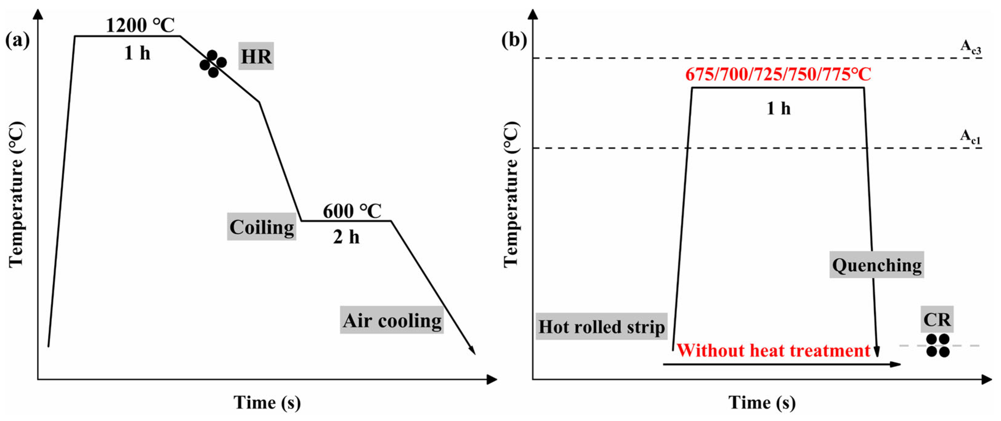
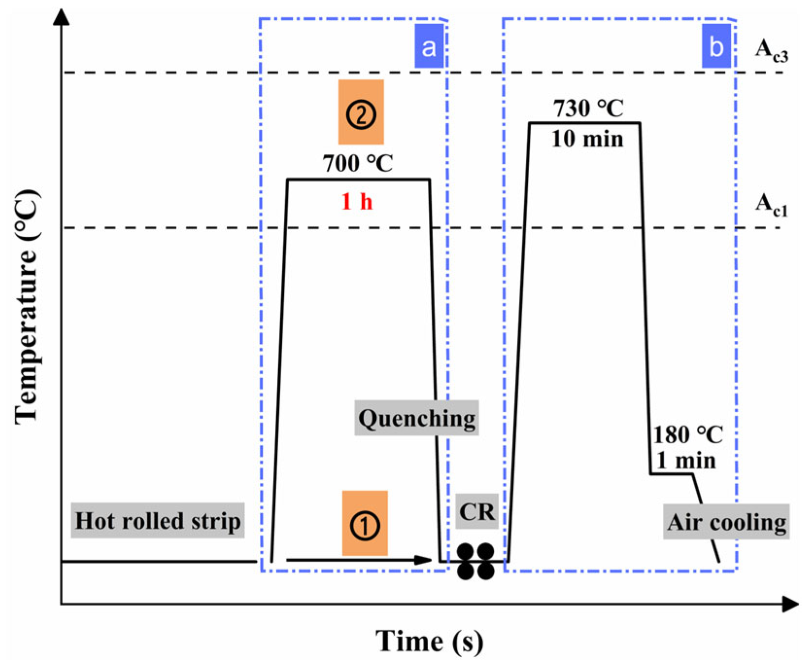
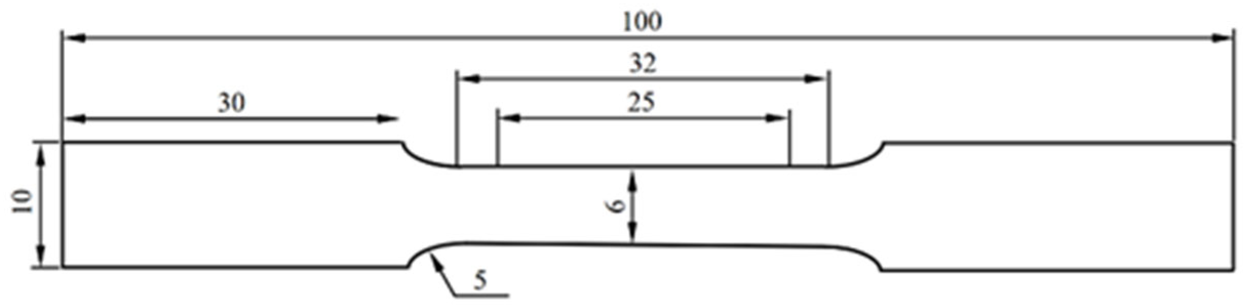
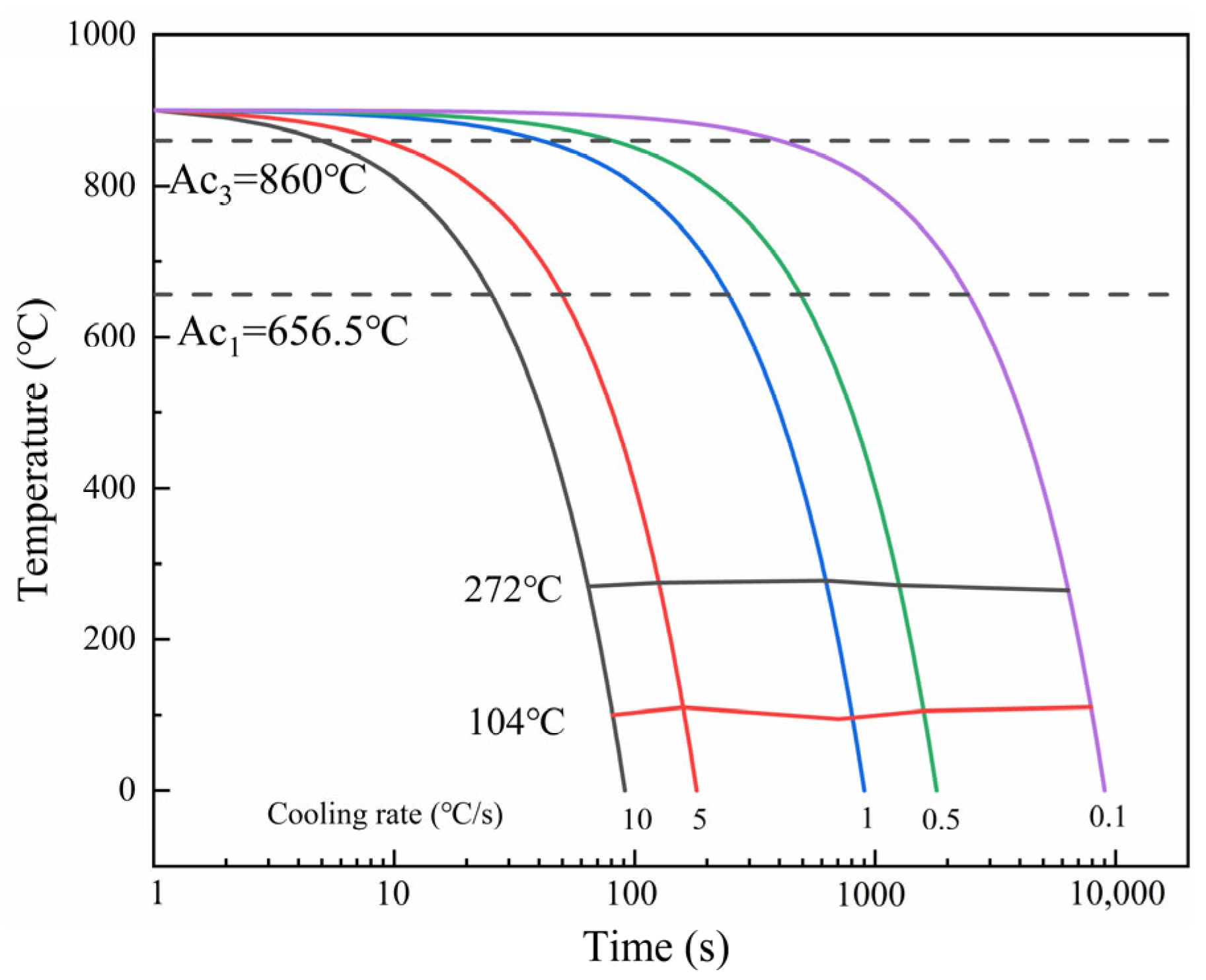
2. Materials and Experimental Procedure

The sample was taken from a hot-rolled, coiled, and air-cooled steel strip with a thickness of 3.2 mm, as shown in Figure 1a, for the hot-rolling process. Table 1 lists the chemical composition of the sample.
To determine the intermediate annealing temperature before cold rolling, annealing experiments were conducted on hot-rolled steel strip samples. The temperature range was 675~775 °C (ΔT = 25 °C), with an annealing time of 1 h, followed by water quenching. The intermediate annealing process is illustrated in Figure 1b.
The specimens were subjected to cold rolling and quenching and partitioning (Q&P) with and without intermediate annealing. The specific process schemes are shown in Figure 2. The thickness of the specimens after cold rolling was 2.1 mm. After cold rolling, the sample undergoes Q&P heat treatment, which involves holding at 730 °C for 10 min and quenching in a 180 °C salt bath for 1 min (as shown by the blue dashed box b in Figure 2). The blue dashed box a indicates whether an intermediate annealing process has been carried out, where Schemes ① and ② correspond to different processes. The specimens without intermediate annealing underwent direct cold rolling followed by heat treatment (blue dashed box b process) to obtain 600CR (Scheme ①), while the specimens with intermediate annealing underwent cold rolling followed by heat treatment (blue dashed box b process) to obtain 700CR (Scheme ②).
The thermal dilatation tests were conducted on a L78Rita/D/Q thermal dilatometer, with specimen dimensions of Φ3 mm × 10 mm. The sample was heated at a rate not exceeding 200 °C/h to 900 °C to obtain Ac1 and Ac3 temperatures. Afterwards, the samples were heated to 900 °C for 10 min and cooled to room temperature at different cooling rates to obtain the Ms and Mf temperatures. Microstructural observations were carried out using a ZEISS Gemini 500 (Carl Zeiss AG, Oberkochen, Baden-Württemberg, Germany) scanning electron microscope (SEM). Electron back scatter diffraction (EBSD) was employed to determine phase orientation and composition. The EBSD sample underwent multiple rounds of grinding and polishing, followed by electrolytic polishing in a 10% perchloric acid alcohol solution for approximately 10 s at a voltage of 15 V and a current of 1 A. Measurements were made at 20 kV with a step size of 0.04 μm. The phase and elemental distribution were determined using transmission electron microscopy (TEM). The volume fractions of RA were calculated by X-ray diffraction (XRD) analysis, based on the integrated intensities of the (200)γ, (220)γ, (311)γ, (200)α, and (211)α peaks. The scanning speed is 0.02°/s, and the scanning range is 47°~95°.
Tensile tests were performed on a CMT5605 electronic universal testing machine(SUST, Zhuhai, China), with specimen dimensions as shown in Figure 3. The axial direction of the tensile specimen is parallel to the rolling direction. The stretching speed is 1 mm/min, and the gauge length is 25 mm. In order to analyze the transformation behavior of RA during deformation, calculate the length change (Δ l) of the tensile test specimen after subtracting the elastic deformation stage. Based on this, calculate the length variation distance of Δ l at 10%, 40%, and 70%. Subsequently, the sample was pulled to these specified distances using a static tensile testing machine, and the microstructure near the center of the specimen was observed at different degrees of tensile testing.

3. Results and Discussion

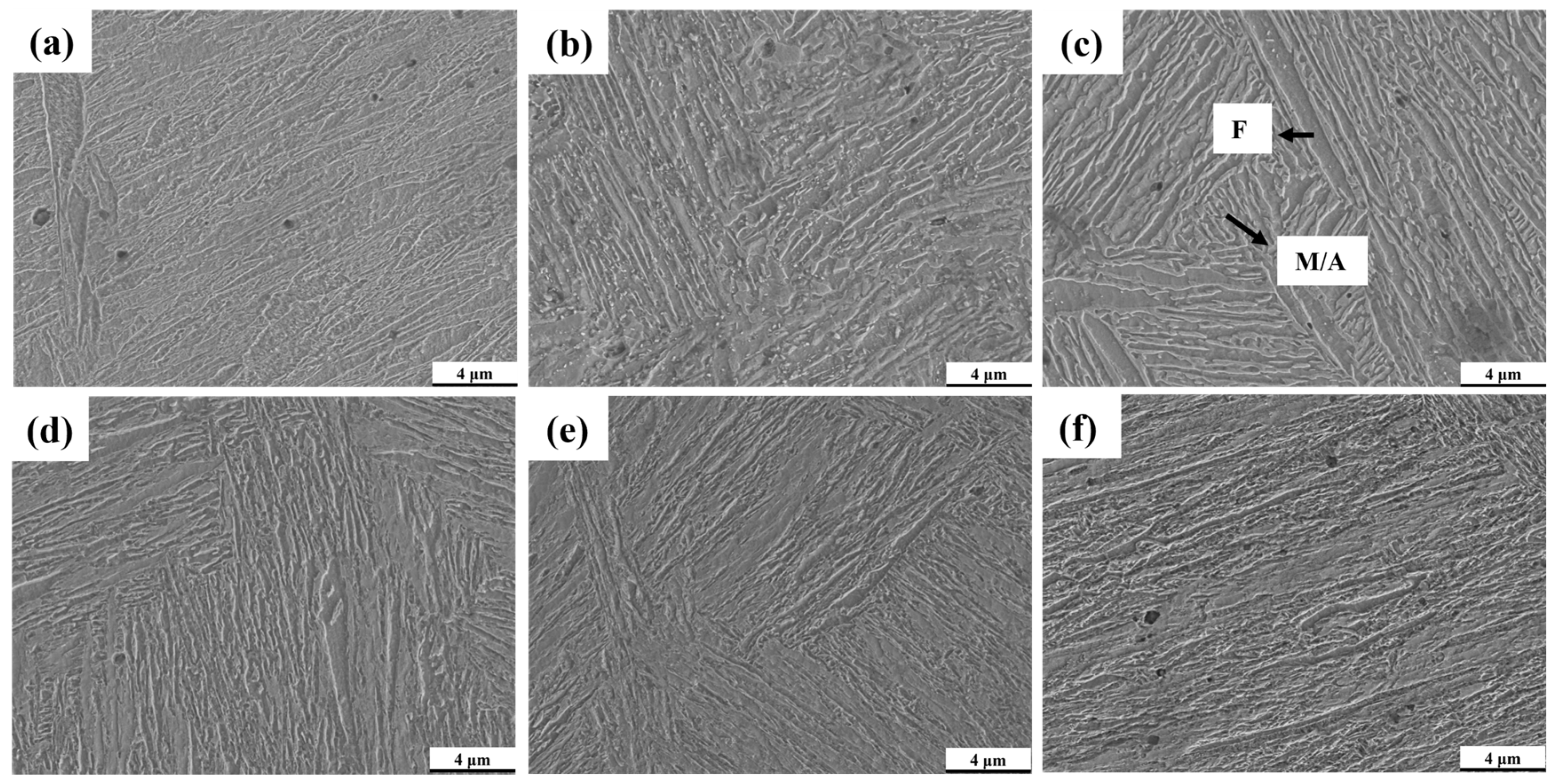
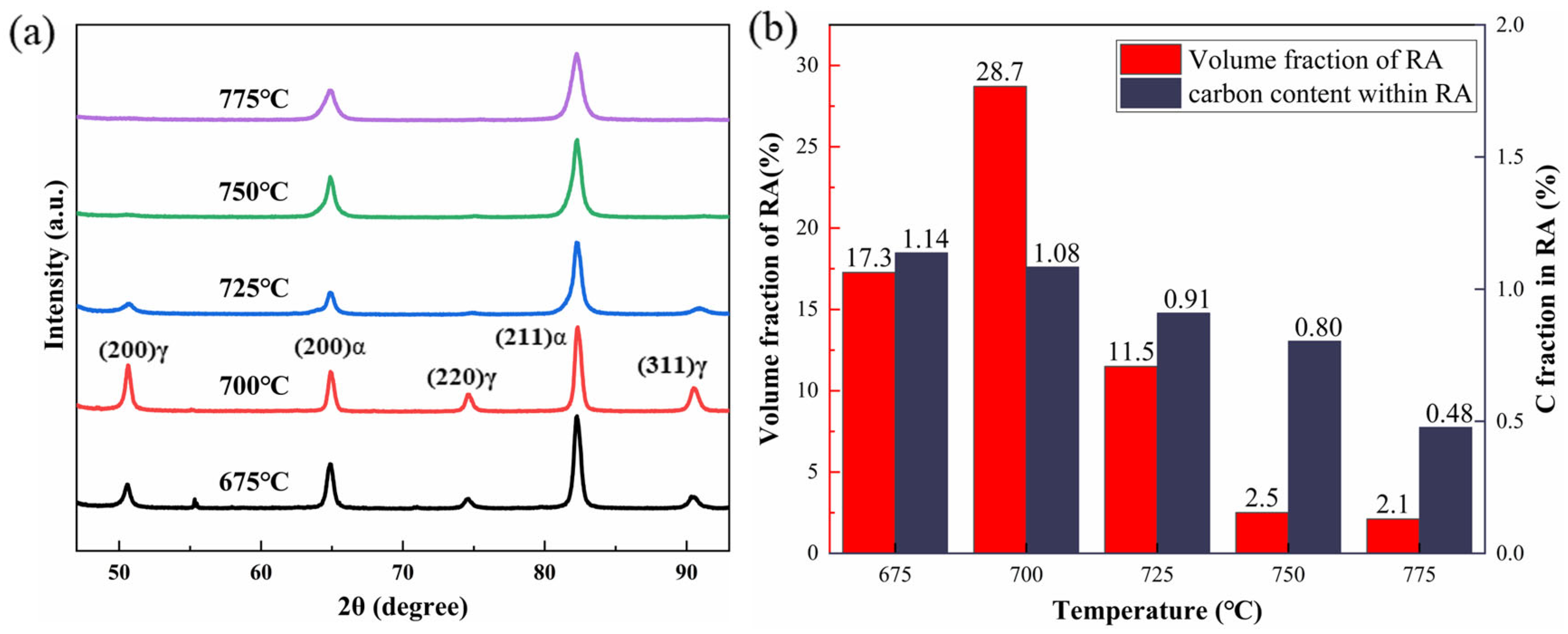
3.1. Intermediate Annealing Temperature

The thermal dilatation tests of hot rolled strip samples were carried out at cooling rates of 0.1 °C/s, 0.5 °C/s, 1 °C/s, 5 °C/s, and 10 °C/s. Figure 4 shows the continuous cooling transformation curve (CCT) of the MMS in the experiment. The thermal dilatation data indicate that only the martensitic phase transformation occurred with the change in cooling rate from 0.1 °C/s to 10 °C/s. The temperature range for the two-phase region is 657 °C to 860 °C.
The microstructure observation of the specimens before and after intermediate annealing (Figure 5) and the XRD detection of residual austenite (RA) (Figure 6) were conducted. It can be seen from Figure 5a that a martensite structure is formed after coiling of hot rolled strip of MMS. The microstructure after intermediate annealing mainly consists of F, RA, and M. From Figure 5b, the presence of cementite was observed at lower two-phase region annealing temperatures. As the annealing temperature increased, the amount of cementite gradually decreased, until at 725 °C annealing, the cementite structure was basically not observed. The XRD results at different intermediate annealing temperatures show that the residual austenite content is highest after annealing at 700 °C. This is related to the disappearance of some cementite and the redistribution of more alloying elements into the austenite [24]. With the increase in annealing temperature, more BCC phases undergo austenitization, but the cementite has disappeared. There is not enough alloy element and carbon element to supplement [9]. The increase in austenite content is not coordinated with the replenishment of elements, leading to a decrease in the stability of austenite in the steel and resulting in more martensite after quenching. An increase in annealing temperature leads to a decrease in RA content and the carbon content within RA, with a significant decrease at 725 °C. Annealing at 700 °C yields the highest RA volume fraction (28.71%) and a higher carbon content in the austenite (1.08%). The dissolution of cementite in the steel results in the solid solution of elements into the residual austenite, with an appropriate presence of ferrite in the structure. Therefore, 700 °C is determined to be the ideal temperature for intermediate annealing.

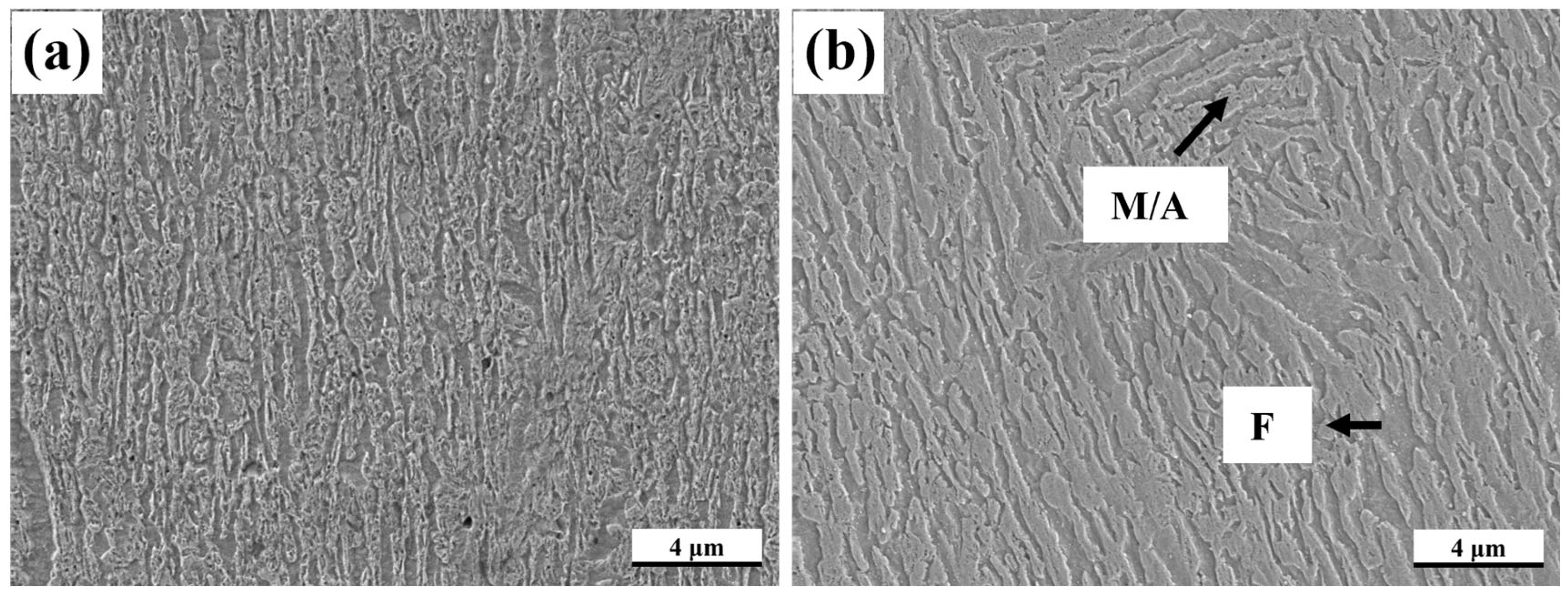
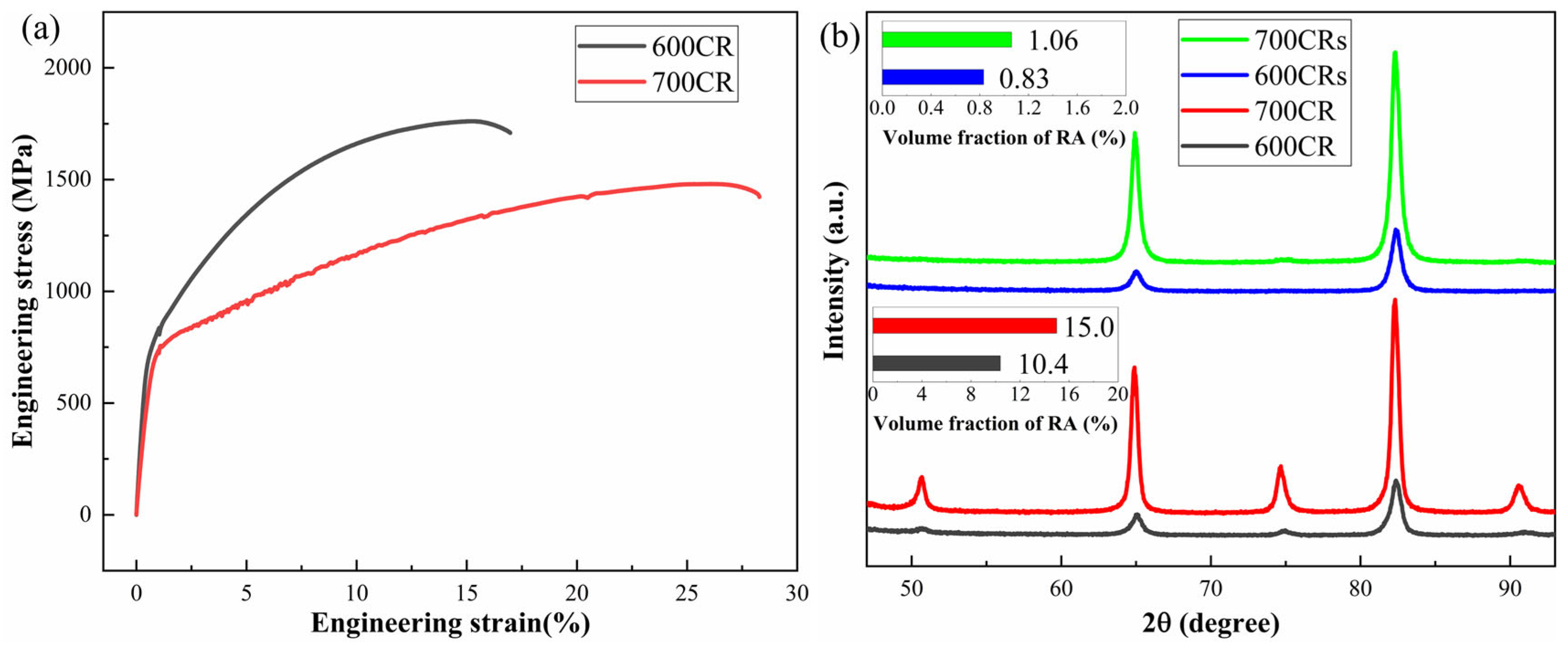
3.2. Microstructure and Properties of 600CR and 700CR Processes

Figure 7 shows the final microstructures of the 600CR and 700CR processes, primarily composed of M, F, and RA phases. The F retains its original state before quenching, while some RA is preserved due to higher element concentration. Tensile specimens in the rolling direction were used for tensile testing of the two process samples, and the results are shown in Figure 8a and Table 2. The 600CR sample exhibits good tensile strength but low elongation, while the 700CR sample demonstrates high elongation and strong plastic product. Plastic product represents the tensile strength and elongation of products, which are comprehensive performance indicators that characterize the strength and toughness level of metal materials. XRD analysis was conducted on the samples from both processes before and after tensile testing to determine the RA content, as shown in Figure 8b. The 600CRs and 700CRs represent the specimens after tensile fracture of 600CR and 700CR, respectively. The volume fractions of RA of 600CR and 700CR specimens before tensile testing are 10.4% and 15%, respectively. The RA content in both the 600CRs and 700CRs samples is nearly equal. To study the stability of RA, the exponent decay law proposed by Sugimoto et al. is introduced [25,26,27,28]:
k ε = ln ( f γ / f 0 )
where f 0 is the volume fraction of RA in the steel before deformation, and f γ is the volume fraction of RA when the strain is ε. k is the austenite stability index. The smaller the k value, the more stable the austenite. The ε values at the time of fracture for 600CR and 700CR samples are 0.17 and 0.27, respectively. The k values of the 600CR and 700CR samples were calculated to be 14.9 and 9.8, respectively. Therefore, the RA of 700CR is more stable. However, there are many factors affecting the stability of RA, including austenite size, morphology, etc. EBSD was used to further analyze the role of retained austenite in steel.
Figure 9 shows the EBSD data of samples with 600CRs and 700CRs. Among them, Kernel Average Misalignment (KAM) is applied to analyze the degree of change in local orientation differences within grains. The higher the KAM value, the higher the level of deformation [29]. The average grain sizes of the 600CRs and 700CRs samples are 0.91 μm and 1.25 μm, respectively. The grain size of 600CRs is significantly smaller, which is related to the pinning effect of undissolved carbides. The fine grains make a significant contribution to the material’s strength, laying the foundation for the high strength of 600CR. The RA content of 600CR is lower, leading to a shorter duration of the TRIP effect, earlier martensitic transformation, and the absorption of some stress by the fine ferrite and residual austenite during martensitic transformation, coordinating the deformation of the structure. This is also the reason for the high tensile strength of 1762 MPa of 600CR. Figure 10 is a magnified view of Figure 9. From Figure 10(a1), it can be seen that the stress of the large BCC grains is almost negligible, but stress is formed at the grain boundaries due to rotation towards the deformation direction. As shown in Figure 10(b1) at position ①, the stress at this position is released after the transformation of RA to M, showing lower stress values. However, at position ②, some blocky RA has not undergone phase transformation, leading to higher stress values at this position. In Figure 10(b2), the RA is film-like, and the entire residual austenite remains relatively intact with a low KAM value. At this point, the M grains exhibit a preferred orientation to provide strength to the material, while the RA contributes to both strength and ductility. The rotation and phase transformation of RA grains lead to local stress relaxation, delaying the occurrence of cracks and improving the ductility of materials [29].
Figure 11 shows the TEM data of the 700CR before tensile testing, where thin film-like RA can be observed between the martensite platelets, as well as blocky ferrite. The elemental surface scan results indicate that both M and RA contain a higher concentration of Mn elements, while the Mn content in F is relatively low. The high concentration of Mn increases the stability of RA. This is an important reason why RA is preserved after two-phase zone annealing. However, the stability of retained austenite depends not only on the degree of element enrichment, but also on the grain morphology and size, which is also the difference in the stability of austenite shown in Figure 10(b1,b2).

3.3. Mechanism of Phase Change Plasticization

Figure 12 presents the EBSD data of the 700CR tensile specimen with a deformation degree of 10%. The IPF diagram is used to represent the orientation distribution of grains. The RA content is high in the microstructure, and large-sized blocky RA is uniformly distributed within the BCC phase. As shown in Figure 12a, the volume fraction of RA is 14.8%. Compared to the pre-tensile test data, the content of RA remains almost unchanged. When the deformation degree is 10%, the stress concentration is smaller, as indicated by the arrow position in Figure 12b. Figure 12c shows the IPF map in the Y-axis (deformation direction), with blue areas leaning more towards the <111> direction. It can be observed that due to the small degree of tensile deformation, the grain orientation at this point is relatively random, with some grains retaining the orientation from cold rolling, while others have lost their original orientation due to recrystallization or phase transformation. When the specimen undergoes deformation, dislocations in F and RA begin to proliferate, and grains start to rotate. Due to the significant difference in strength between ferrite and martensite, stress concentrations easily occur between blocky ferrite and martensite, especially in small recrystallized grains. In Figure 12d, the arrows indicate small equiaxed grains, all of which have low-angle grain boundaries. The different grain boundary angles correspond to varying degrees of stress concentration. High-angle grain boundaries hinder dislocation movement, making grains less deformable, while low-angle grain boundaries offer weaker resistance to dislocation movement, resulting in easier grain deformation and stress concentration [30,31,32]. The stress values of the residual austenite in the KAM map are generally low, with most not undergoing phase transformation, and there is almost no deformation martensite in the material.
Figure 13 shows the EBSD data for the 700CR tensile sample with a deformation of 40%, where a large amount of RA undergoes phase transformation, resulting in a RA volume fraction of 4%. The IPF map indicates a tendency for grain orientation consistency, suggesting a significant strain level at this point. Multiple BCC grains at the white arrow in Figure 13 exhibit consistent orientations, and the KAM map reveals low internal stress values within these grains, while stress concentration exists in the periphery, indicating that they maintain a preferred orientation due to cold rolling even after heat treatment. As the sample deforms, they undergo collective rotation, leading to severe deformation of the surrounding residual austenite after phase transformation. The rotation and deformation of ferrite absorb energy in the early stage, driving the rotation of residual austenite and martensite. When studying the deformation mechanism of dual-phase high manganese steel at different deformation stages, many scholars have found two ways for the transformation of residual austenite to martensite: γ→ε→α′ and γ→α′ [33,34,35]. When subjected to external force, RA first undergoes rotation and deformation. As the stress increases, dislocation energy accumulates to a certain extent, causing the lattice of RA to rotate. Due to the large lattice distortion and hindered atomic movement, high Mn-containing RA is not easily transformed into α′ martensite, thus forming the intermediate HCP crystal structure of ε martensite. However, the formation of ε martensite generally occurs in residual austenite with higher Mn content, while the Mn content in 700CR is limited, resulting in a small amount of ε martensite formed during deformation. It is worth noting that a large amount of RA transforms into α′ martensite during deformation, especially blocky RA, and the transformation of clustered blocky residual austenite can protect the central RA, hindering the transformation of blocky RA. Figure 14 is a local enlarged image of point A in Figure 13, showing the surviving blocky RA surrounded by BCC with consistent orientations. Stress concentration still occurs at small-angle grain boundaries in the KAM map. However, compared to Figure 12b, it is evident that the internal stress in the 40% tensile sample has significantly decreased, indicating that the phase transformation of a large amount of RA has absorbed most of the stress, alleviating stress concentration in the sample.
Figure 15 shows the EBSD data of a 700CR tensile specimen deformed to 70% strain, where most of the RA undergoes phase transformation, resulting in a RA fraction of 2.1%. At this stage, the orientation of the grains is evident. As the deformation process progresses, the number of low-angle grain boundaries decreases continuously, from 53.5% at 10% strain to 40.8%, indicating that increasing stress promotes grain rotation and the formation of more high-angle grain boundaries to hinder dislocation motion. The KAM map indicates that the material has generally high stress values. When the tensile strain reaches 40%, a large amount of RA undergoes phase transformation, absorbing most of the stress. As the tensile deformation continues, the applied stress needs to be borne by other microstructural features. A small fraction of the transformed martensite derived from the deformation of the RA transforms into α’ martensite after dislocation multiplication, but more stress requires the deformation of newly formed martensite to bear. Both ferrite and martensite continue to deform, and martensite significantly contributes to the tensile strength and brittleness of the material. When there is a misalignment between ferrite and martensite deformation, cracks initiate and propagate at the interface between martensite and ferrite, leading to necking and fracture of the specimen.
In the initial stages of specimen deformation, most of the external force is absorbed by the proliferation of dislocations and grain rotation. Dislocation accumulation occurs at the grain boundaries of F and RA, with the softest F deforming first at stress concentration sites. As stress increases, dislocations continue to proliferate, and stacking faults increase. Unstable blocky RA easily transforms into deformed M. With increasing stress, more RA undergoes phase transformation, leading to a continuous increase in deformed M content. When RA no longer serves as the primary absorber of external force, a small amount of ε martensite transforms into α’ martensite, which then experiences significant stress. Both the phase transformation and deformation of M require greater external force, with M deformation necessitating coordination between F and RA. After the TRIP effect ends, the plasticity provided by F and the strength of M contribute to the mechanical properties of the specimen until performance instability leads to fracture.

4. Conclusions

To reduce cold rolling cracking and increase the proportion of RA after rolling, an intermediate annealing process was conducted before cold rolling. The mechanical properties and microstructures of samples without intermediate annealing and with intermediate annealing before cold rolling and subsequent QP treatment were compared. The influence of microstructure on the mechanical properties of multiphase steel was discussed, and the phase transformation plasticity mechanism of RA during tensile deformation was analyzed. The conclusions are as follows:
  • It was confirmed that the intermediate annealing temperature of the dual-phase zone before cold rolling at 700 °C could achieve a high proportion of RA and F. The higher carbon content in RA increased the stability of RA, thereby reducing the occurrence of cracking during cold rolling.
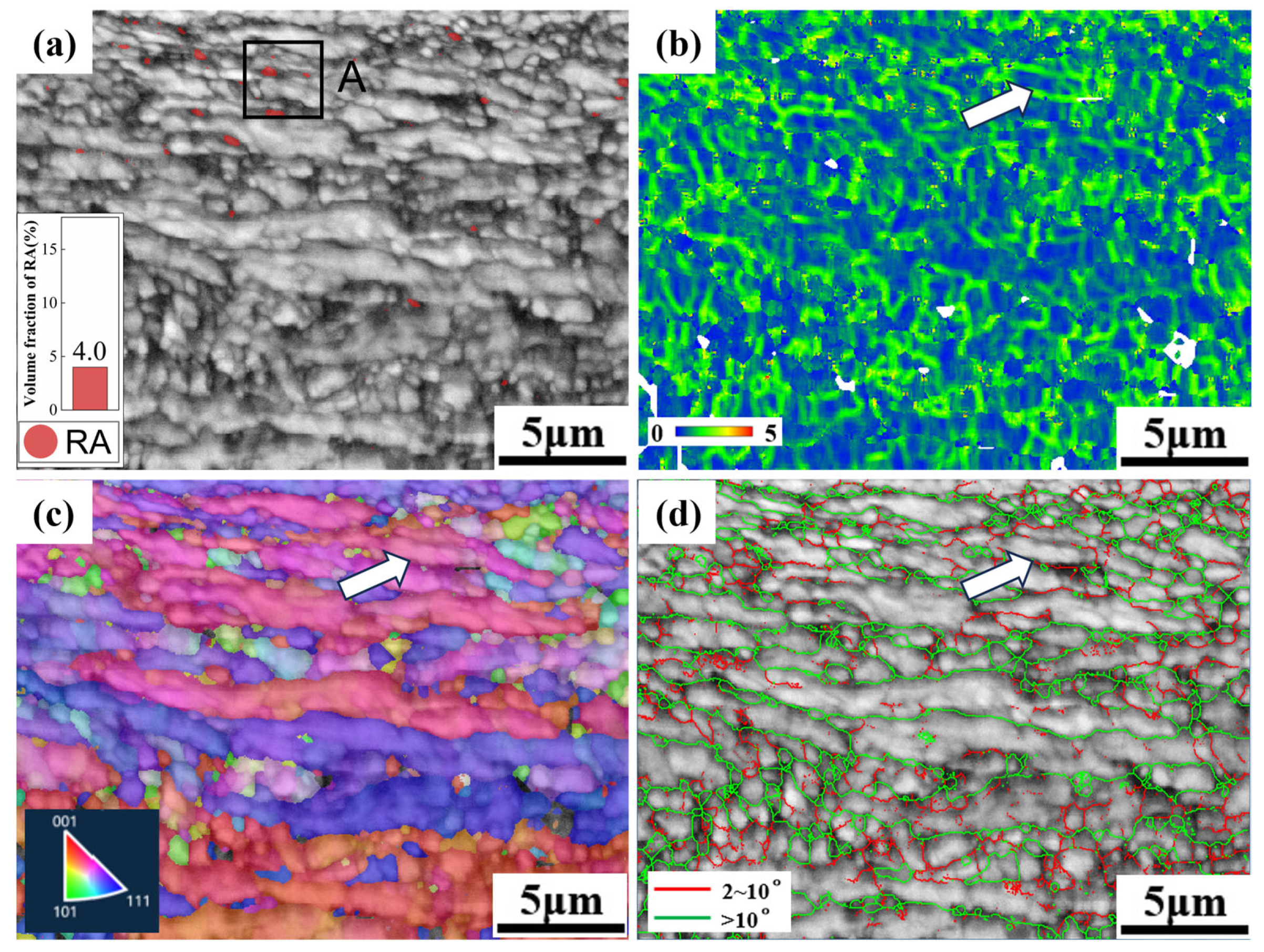
  • The 600CR sample exhibited a tensile strength of nearly 1760 MPa, but with relatively low elongation. The 700CR sample achieved an RA content of nearly 15% and a high strong plastic product of 37.4 GPa%.
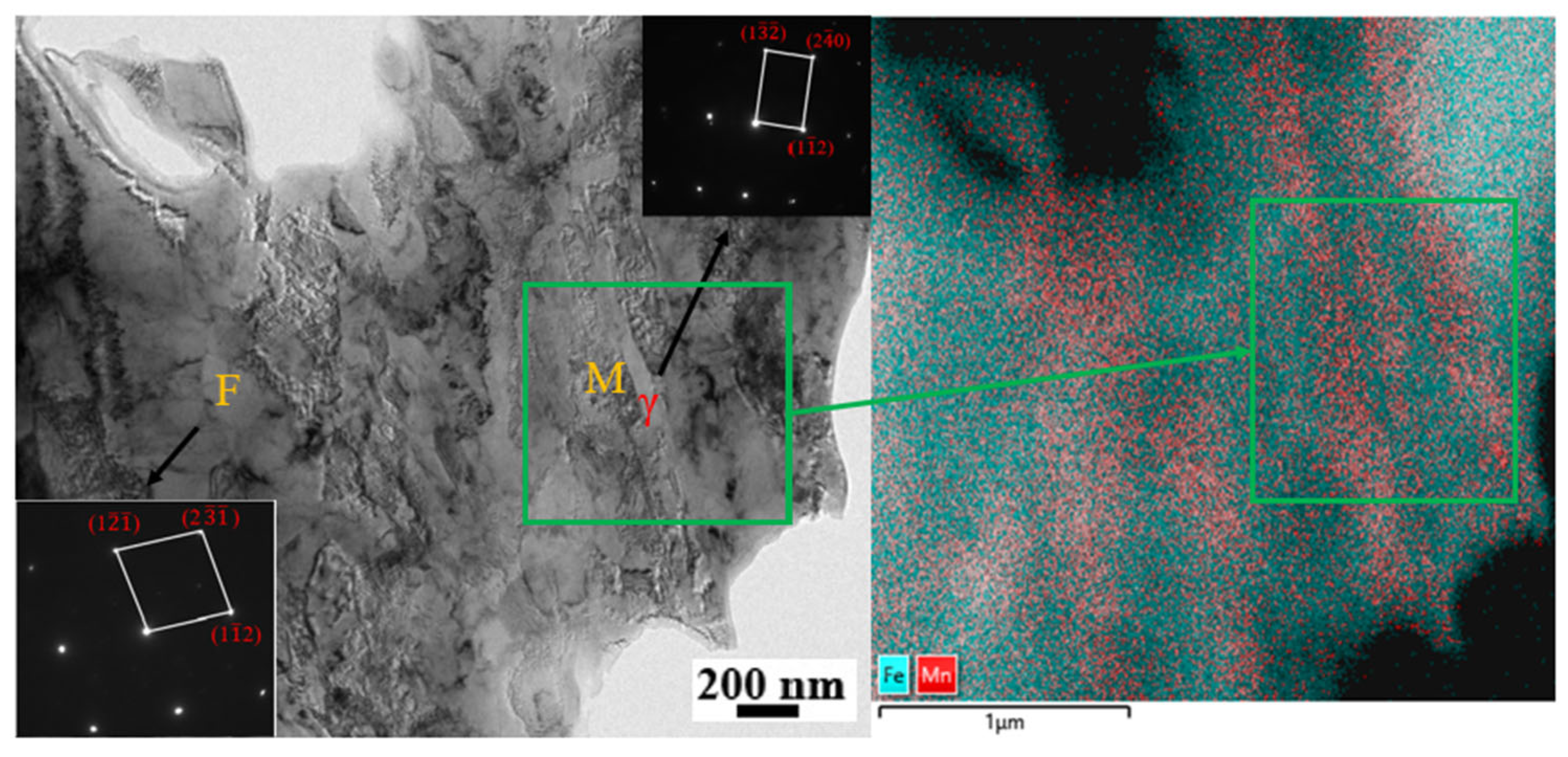
  • RA undergoes phase transformation during deformation to absorb deformation stress, especially in the form of fine, evenly distributed lamellar austenite. F, as the material that undergoes deformation first, provides some plasticity to the structure. As strain increases, RA engages in phase transformation plasticity mechanisms until M undergoes deformation. M significantly contributes to material strength but is also prone to crack initiation. When RA is depleted, the discordance in properties between F and M leads to crack propagation and ultimately fracture.

Author Contributions

Conceptualization, S.Y. and K.C.; Methodology, S.Y. and K.C.; Software, D.W. and J.C.; Investigation, S.Y. and D.W.; Visualization, D.W. and J.C.; Formal Analysis, K.C. and J.C.; Supervision, D.W. and A.Z.; Writing—Original Draft Preparation, S.Y. and J.C.; Writing—Review and Editing, S.Y., K.C. and A.Z.; Project Administration, A.Z.; Funding acquisition, A.Z. All authors have read and agreed to the published version of the manuscript.

Funding

This work was supported by the Fundamental Research Funds for the Central Universities (FRF-BD-23-02).

Data Availability Statement

The data presented in this study are available on request from the corresponding author. (The data are not publicly available due to privacy or ethical restrictions.)

Acknowledgments

We thank the Tsinghua Institute of Mechanics for providing the high-definition field emission scanning electron microscope. The thermal dilatometer was provided by the State Key Laboratory of Iron and Steel Metallurgy New Technology, Beijing University of Science and Technology. The use of transmission electron microscopy was supported by the ZKKF(Beijing) Science and Technology Co., Ltd.

Conflicts of Interest

Author Junming Chen is employed by: Beijing Guowang Fuda Science and Technology Development Co., Ltd. The other authors declare no conflicts of interest.

References

  1. Qiao, Y.; Zheng, Z.; Yang, H.; Long, J.; Han, P.X. Recent progress in microstructural evolution, mechanical and corrosion properties of medium-Mn steel. J. Iron Steel Res. Int. 2023, 30, 1463–1476. [Google Scholar] [CrossRef]
  2. Dai, Z.; Chen, H.; Ding, R.; Lu, Q.; Zhang, C.; Yang, Z.; van der Zwaag, S. Fundamentals and application of solid-state phase transformations for advanced high strength steels containing metastable retained austenite. Mater. Sci. Eng. R Rep. 2021, 143, 100590. [Google Scholar] [CrossRef]
  3. Burda, I.; Zweiacker, K.; Arabi-Hashemi, A.; Barriobero-Vila, P.; Stutz, A.; Koller, R.; Roelofs, H.; Oberli, L.; Lembke, M.; Affolter, C.; et al. Fatigue crack propagation behavior of a micro-bainitic TRIP steel. Mater. Sci. Eng. A 2022, 840, 142898. [Google Scholar] [CrossRef]
  4. Yi, H.L.; Lee, K.Y.; Bhadeshia, H.K.D.H. Mechanical stabilisation of retained austenite in δ-TRIP steel. Mater. Sci. Eng. A 2011, 528, 5900–5903. [Google Scholar] [CrossRef]
  5. Li, G.Q.; Shen, Y.F.; Jia, N.; Feng, X.W.; Xue, W.Y. Microstructural evolution and mechanical properties of a micro-alloyed low-density δ-TRIP steel. Mater. Sci. Eng. A 2022, 848, 143430. [Google Scholar] [CrossRef]
  6. Emamian, Y.; Kolahi, A.; Palizdar, Y. Evaluation of microstructures and mechanical properties of deltha trip steel with different vanadium contents. Results Mater. 2024, 21, 100530. [Google Scholar] [CrossRef]
  7. Miller, R.L. Ultrafine-grained microstructures and mechanical properties of alloy steels. Metall. Trans. 1972, 3, 905–912. [Google Scholar] [CrossRef]
  8. Kozłowska, A.; Morawiec, M.; Skowronek, A.; Grajcar, A.; Matus, K.; Nuckowski, P.M. Enhancing mechanical properties of hot-rolled Al-alloyed medium-Mn steel by novel double-step intercritical annealing. Mater. Sci. Eng. A 2023, 865, 144650. [Google Scholar] [CrossRef]
  9. Kalsar, R.; Sanamar, S.; Schell, N.; Brokmeier, H.-G.; Saha, R.; Ghosh, P.; Bhagat, A.; Suwas, S. Elemental partitioning in medium Mn steel during short-time annealing: An in-situ study using synchrotron x-rays. Materialia 2020, 9, 100594. [Google Scholar] [CrossRef]
  10. Song, C.; Zhang, Z.; Wu, W.; Wang, H.; Cheng, Z.; Sun, Z.; Xia, Y.; Yin, W.; Yu, H. Effect of Si on the deformation behavior of retained austenite and annealed martensite in medium Mn steels. Mater. Sci. Eng. A 2024, 899, 146451. [Google Scholar] [CrossRef]
  11. Song, C.; Zhang, Z.; Wu, W.; Wang, H.; Sun, Z.; Yang, Y.; He, W.; Xu, J.; Xia, Y.; Yin, W.; et al. Effect of Si on the dislocation state within martensite of ultra-high strength hot-rolled medium Mn steel with good ductility. Mater. Sci. Eng. A 2023, 869, 144825. [Google Scholar] [CrossRef]
  12. Yuzbekova, D.; Dudko, V.; Kniaziuk, T.; Kaibyshev, R. Tempering behavior of an ultra-high-strength steel with 1.6 wt% Si at low to medium temperatures. Mater. Sci. Eng. A 2024, 896, 146264. [Google Scholar] [CrossRef]
  13. Li, T.; Yan, S.; Liu, X. Microstructure and tensile behaviors for a medium Mn steel with δ-ferrite phase under different annealing temperatures. J. Mater. Res. Technol. 2021, 15, 708–718. [Google Scholar] [CrossRef]
  14. Kumar, A.; Blessto, B.; Singh, A. Development of a low-carbon carbide-free nanostructured bainitic steel with extremely high strength and toughness. Mater. Sci. Eng. A 2023, 877, 145–186. [Google Scholar] [CrossRef]
  15. Hasan, S.M.; Ghosh, M.; Chakrabarti, D.; Singh, S.B. Development of continuously cooled low-carbon, low-alloy, high strength carbide-free bainitic rail steels. Mater. Sci. Eng. A 2020, 771, 138590. [Google Scholar] [CrossRef]
  16. Long, X.; Liu, W.; Zhu, R.; Zhang, Y.; Zhang, F.; Yang, Z.; Li, Y. Effect of the cooling rate in the medium temperature zone on the phase transformation and microstructure of carbide-free bainitic steel. J. Mater. Res. Technol. 2024, 29, 50–66. [Google Scholar] [CrossRef]
  17. Zhang, T.; Wang, L.; Wang, Y.; Hu, J.; Di, H.; Xu, W. Tailoring bainitic transformation and enhancing mechanical properties of carbide-free bainitic steel via high-temperature ausforming. Mater. Sci. Eng. A 2022, 852, 143677. [Google Scholar] [CrossRef]
  18. Xu, N.; Wang, L.; Hu, J.; Chai, Z.; Zhao, W.; Xu, W. Promoting ductility and formability in a carbide free bainitic steel via pre-annealing treatment. Mater. Charact. 2023, 204, 113205. [Google Scholar] [CrossRef]
  19. Speer, J.; Matlock, D.K.; De Cooman, B.C.; Schroth, J.G. Carbon partitioning into austenite after martensite transformation. Acta Mater. 2003, 51, 2611–2622. [Google Scholar] [CrossRef]
  20. Cabo Rios, A.; Arlazarov, A.; Charbonnier, N.; De Diego-Calderón, I. Characterization and modelling of microstructure evolution during partitioning in Q&P steels. Materialia 2024, 33, 101981. [Google Scholar]
  21. Gu, G.; Kim, J.H.; Lee, H.H.; Zargaran, A.; Koo, M.; Kim, S.H.; Lee, J.S.; Suh, D.W. Room temperature quenching and partitioning (RT-Q&P) processed steel with chemically heterogeneous initial microstructure. Mater. Sci. Eng. A 2022, 851, 143651. [Google Scholar]
  22. Parthiban, R.; Ray, R.K.; Hari Kumar, K.C.; Sankaran, S. Influence of rolling temperature and strain on the microstructural evolution and mechanical properties in quench and partition (Q&P) steels. Mater. Sci. Eng. A 2021, 825, 141893. [Google Scholar]
  23. Wang, X.; Xu, Y.; Wang, Y.; Li, J.; Wang, Y.; Gu, X.; Misra, R. Combined effect of Cu partitioning and nano-size precipitates on improving strength-ductility balance of Cu bearing Q&P steel. Mater. Charact. 2022, 194, 112441. [Google Scholar]
  24. Li, T.; Yan, S.; An, D.; Li, X.; Chen, J. Austenite transformation associated with δ-ferrite phase in a medium-Mn steel after cold-rolling and intercritical annealing. J. Mater. Process. Technol. 2022, 306, 117632. [Google Scholar] [CrossRef]
  25. Sugimoto, K.; Kobayashi, M.; Hashimoto, S. Ductility and strain-induced transformation in a high-strength transformation-induced plasticity-aided dual-phase steel. Metall. Trans. 1992, 23, 3085–3091. [Google Scholar] [CrossRef]
  26. Sherif, M.Y.; Mateo, C.G.; Sourmail, T.; Bhadeshia, H.K.D.H. Stability of retained austenite in TRIP-assisted steels. Mater. Sci. Technol. 2004, 20, 319–322. [Google Scholar] [CrossRef]
  27. Shi, J.; Sun, X.; Wang, M.; Hui, W.; Dong, H.; Cao, W. Enhanced work-hardening behavior and mechanical properties in ultrafine-grained steels with large-fractioned metastable austenite. Scr. Mater. 2010, 63, 815–818. [Google Scholar] [CrossRef]
  28. Zhang, Y.; Ye, Q.; Yan, Y. Processing, microstructure, mechanical properties, and hydrogen embrittlement of medium-Mn steels: A review. J. Mater. Sci. Technol. 2024, 201, 44–57. [Google Scholar] [CrossRef]
  29. Zou, Y.; Gao, Q.; Ding, H.; Tang, Z. Effect of heterogeneous microstructure on martensitic transformation behavior and mechanical properties of a cold rolling medium Mn steel. Mater. Sci. Eng. A 2023, 885, 145630. [Google Scholar] [CrossRef]
  30. Kwok, T.W.J.; Gong, P.; Rose, R.; Dye, D. The relative contributions of TWIP and TRIP to strength in fine grained medium-Mn steels. Mater. Sci. Eng. A 2022, 855, 143864. [Google Scholar] [CrossRef]
  31. Khan, A.S.; Baig, M.; Choi, S.H.; Yang, H.S.; Sun, X. Quasi-static and dynamic responses of advanced high strength steels: Experiments and modeling. Int. J. Plast. 2012, 30–31, 1–17. [Google Scholar]
  32. Choi, S.H.; Kim, E.Y.; Woo, W.; Han, S.H.; Kwak, J.H. The effect of crystallographic orientation on the micromechanical deformation and failure behaviors of DP980 steel during uniaxial tension. Int. J. Plast. 2013, 45, 85–102. [Google Scholar] [CrossRef]
  33. Tian, G.; Li, Z.; Yao, S.; Cui, Y.; Zhao, A. Partitioning of C and Mn During Intercritical Annealing and Transformation of Retained Austenite During Deformation in Medium Mn Steel. Steel Res. Int. 2023, 94, 2200731. [Google Scholar] [CrossRef]
  34. Seong, B.S.; Shin, E.; Choi, S.H.; Choi, Y.; Han, Y.S.; Lee, K.H.; Tomota, Y. Quantitative analysis of fine nano-sized precipitates in low-carbon steels by small angle neutron scattering. Appl. Phys. A 2010, 99, 613–620. [Google Scholar] [CrossRef]
  35. Kim, E.Y.; Yang, H.S.; Han, S.H.; Kwak, J.H.; Choi, S.H. Effect of initial microstructure on strain-stress partitioning and void formation in DP980 steel during uniaxial tension. Met. Mater. Int. 2012, 18, 573–582. [Google Scholar] [CrossRef]
Figure 1. Schematic diagram of heat treatment process: (a) hot rolling process; (b) intermediate annealing process.
Metals 15 00500 g001
Figure 2. 600CR and 700CR process diagram. The blue dashed box a represents whether to perform intermediate annealing; The blue dashed box b represents the Q&P heat treatment process.
Metals 15 00500 g002
Figure 3. Dimensions of tensile specimen (unit: mm).
Metals 15 00500 g003
Figure 4. Continuous cooling transition curve of MMS.
Metals 15 00500 g004
Figure 5. Microstructure of hot rolled strip after coiling (a). Microstructure after intermediate annealing at (b) 675 °C, (c) 700 °C, (d) 725 °C, (e) 750 °C, (f) 775 °C.
Metals 15 00500 g005
Figure 6. XRD data after different intermediate annealing temperatures: (a) XRD curve; (b) the volume fraction of RA and the carbon content inside RA.
Metals 15 00500 g006
Figure 7. SEM images of (a) 600CR and (b) 700CR sample.
Metals 15 00500 g007
Figure 8. (a) Engineering stress–strain curves under different processes; (b) XRD curves before and after tensile testing and volume fraction of RA.
Metals 15 00500 g008
Figure 9. The EBSD diagram: (a) 600CRs; (b) 700CRs.
Metals 15 00500 g009
Figure 10. The enlarged graphs of a1, b1, and b2 in Figure 9.
Metals 15 00500 g010
Figure 11. TEM image of 700CR sample.
Metals 15 00500 g011
Figure 12. EBSD diagram of 10% deformation degree of 700CR tensile specimen. (a) Phase distribution diagram; (b) KAM diagram; (c) IPF diagram; (d) grain boundary diagram.
Metals 15 00500 g012
Figure 13. EBSD diagram of 40% deformation degree of 700CR tensile specimen. (a) Phase distribution diagram; (b) KAM diagram; (c) IPF diagram; (d) grain boundary diagram.
Metals 15 00500 g013
Figure 14. The EBSD data: (a) enlarged figure at box A in Figure 13; (b) grain orientation difference along the arrow direction.
Metals 15 00500 g014
Figure 15. EBSD diagram of 70% deformation degree of 700CR tensile specimen. (a) Phase distribution diagram; (b) KAM diagram; (c) IPF diagram; (d) grain boundary diagram.
Metals 15 00500 g015
Table 1. Chemical composition of hot rolled strip (Wt. %).
CMnSiNbVFe
0.204.801.530.030.062Balance
Table 2. Tensile test data.
Tensile Strength/MPaElongation/%Product/GPa%
600CR176217.1230.17
700CR148127.2837.40
Disclaimer/Publisher’s Note: The statements, opinions and data contained in all publications are solely those of the individual author(s) and contributor(s) and not of MDPI and/or the editor(s). MDPI and/or the editor(s) disclaim responsibility for any injury to people or property resulting from any ideas, methods, instructions or products referred to in the content.

