Abstract
The HP40Nb alloy, commonly used in the petrochemical industry as a heat-resistant material, undergoes significant microstructural changes at high temperatures. This study examined samples from the HP40Nb radiant tube used in a reformer furnace, exposed to 950, 1050, and 1150 °C for 2 and 8 h. Metallographic analysis, including optical microscopy, SEM, EDS, and XRPD, revealed that the as-cast alloy has an austenitic dendritic matrix with primary eutectic-like carbides (M23C6 and MC types). Prolonged exposure to high temperatures transformed the primary carbides into coarse M23C6 forms, losing their lamellar shape. The number of secondary carbides decreased with increasing temperature, and at 1150 °C for 480 min, secondary Cr23C6 carbides nearly decomposed, and Nb carbides dissolved into the austenitic matrix.
1. Introduction
Centrifugally cast heat-resistant alloys of the HP (ASTM A297/ASTM A297-21a [1]) series are used for applications in the manufacture of high-temperature components in petrochemical systems, such as steam reformer tubes, radiation tubes, and ethylene cracking furnace tubes [2,3,4,5]. An HP alloy series, well known for its ASTM designation—where “H” signifies heat resistance and “P” denotes its nickel content—is primarily composed of Fe-25Cr-35Ni-0.4C (by weight) and is widely used in petrochemical furnace applications. Thanks to the unique mechanical properties under service at high temperatures, these alloys have good resistance to corrosion, high oxidation, carburization, and good creep resistance [6,7,8,9,10]. The reformer furnace tubes made of the HP40 (ASTM A608 [11]) alloy are designed for a nominal life of up to 100,000 h. However, the lifespan of these materials is influenced by various mechanisms, including creep, carburization, oxidation, thermal shock, and accidental overheating that occur due to the combined effects of the high service temperatures, mechanical loads, and the duration of service [12,13].
In recent years, there has been growing interest in the application of the centrifugally cast HP40Nb alloy, which has been developed by adding a small amount of niobium to the HP40 alloy [14]. It should be mentioned that the addition of niobium to the HP alloy hinders the precipitation of chromium carbides and improves its mechanical properties, increasing creep strength and creep ductility, as well as carburization resistance [12].
In the as-cast state, the microstructure of HP40Nb alloys features an austenitic matrix interspersed with intergranular and inter-dendritic eutectic-like primary Cr-rich carbides of the M23C6 type and Nb-rich carbides of the MC type. The microstructure of centrifugally cast HP40 reformer tubes is significantly affected by high-temperature service, leading to creep damage and the accumulation of microcracks [15]. This damage is often characterized by the presence of carbides at grain boundaries [16], coarsening of the grain boundaries due to carbide precipitation, and degradation of the mechanical properties [17,18]. These studies collectively underscore the importance of microstructural characterization in understanding the behavior of centrifugally cast steel furnace tubes, particularly in response to short or long high-temperature exposure. Thus, the formation of different carbide morphologies during processing and the expected structures in HP40Nb alloys during aging heat treatment can be understood through a combination of metallography, X-ray diffraction, and electron beam backscattered diffraction techniques [19]. Skindaras et al. [20] further explored the microstructure and mechanical properties of cast alloys with high chromium and nickel content after long-term high-temperature exposure, highlighting the emergence of carbides and other precipitates. The morphology and structure of the carbides in high-alloy steels, including HP40Nb alloys, are influenced by the aging time and secondary carbide precipitation [21]. Specifically, the eutectic carbide morphology in HP alloys changes to more complex shapes with longer aging times, and the presence of secondary carbides can lead to the coalescence of eutectic carbides [22]. The aging of HP40Nb alloys at 1000 °C under air results in the replacement of M7C3 carbides with M23C6 carbides, and the formation of a sub-surface zone depleted in chromium [23]. The inter-dendritic niobium–titanium-rich carbides in HP-NbTi alloys can have blocky or nodular morphologies [24]. The transformation of M7C3 to M23C6 and subsequent secondary carbide precipitation in austenitic matrices is a complex process influenced by various factors. The stability of the M23C6 phase is crucial, with its dissolution affecting the kinetics of the ferrite-to-austenite transformation [25]. The formation of M23C6 from M7C3 is influenced by temperature and time, with the former being a key factor in the transformation [26]. The presence of niobium and titanium in austenitic stainless steels can further complicate the process, with the formation of Z phase and the stability of the MX phase being important considerations [27]. The transformation of M7C3 to M23C6 and the subsequent secondary carbide precipitation are thus influenced by a range of factors, including temperature, time, and the presence of other elements in the steel.
The microstructural development of HP40 alloy micro-alloyed with Nb after overheating at a high-temperature hold is, as stated before, a complex process influenced by various factors. These studies collectively suggest that the microstructural development of an HP40 alloy with Nb is a dynamic process and further research is needed to fully understand its behavior after short-term overheating. Moreover, findings that the content of inter-dendritic carbides is a key factor in its creep performance add to the importance of a better understanding of short-term exposure [23].
Thermal instability results in accelerated microstructural aging, which unequivocally contributes to the premature and unexpected failure of tubes due to bending or cracking [28]. It is essential to recognize that there is a significant gap in our understanding of the fitness for service of tubes that endure a temperature surge without displaying any cracking or visible damage. To ensure the safe and reliable operation of tube materials throughout their lifespan, it is essential to thoroughly verify their mechanical and metallurgical properties. This careful examination acts as a safeguard, confirming that the materials possess the necessary strength and durability to withstand the demands of their application [29]. The evolution processes of carbides and other intermetallic compounds during creep exposure result in a reduction in ductility. This diminished ductility may lead to cracking due to thermal stresses occurring during shut-down and start-up operations, as well as during welding repairs [30]. Enhancing the material’s performance significantly extends their lifespan, thereby reducing both capital costs and environmental impact for each unit of H2 produced [31].
Therefore, the aim of this study was to explore the effect of short-term overheating temperatures on the microstructure and creep behavior of an HP40Nb alloy. This was achieved by discussing the microstructural evolution of HP40Nb alloys during aging, with a focus on the formation of different carbides and transition zones.
The combination of presented techniques has provided new insight into how different carbide types and morphologies form during overheating, and further highlighted the significance of microstructure control and monitoring in utilization of the reformer tubes in extreme conditions.
2. Materials and Methods
2.1. Material
The material investigated in this study was machined out of the centrifugally cast HP40Nb alloy radiant tube used in process of ethylene cracking [2,3]. The chemical composition of the tube material consists of 0.44% C, 1.11% Mn, 1.81% Si, 34.04% Ni, 26.99% Cr, and 0.63% Nb (mass %). The exact locations where the sections were cut on the reformer columns used for ethylene cracking in the respective industrial plant are not known precisely. Specimens for metallographic and mechanical tests were cut from a tube segment 350 mm long, with an outer diameter of 76.2 mm, an inner diameter of 63.5 mm, and a wall thickness of 6.35 mm, using a saw with minimal heating.
The specimens were short-term exposed at high temperatures of 950, 1050, and 1150 °C for 2 and 8 h in an electric furnace under an air atmosphere and subsequently cooled in air. The temperature was controlled by the thermocouple Pt-Pt13%Rh placed just above the samples. At least five samples were tested for each heat treatment condition.
Microstructural observations were performed on the tube samples before and after heat treatment. The morphology and chemical composition of various phases and precipitates were observed and characterized by means of metallography techniques: light microscopy (LM) and scanning electron microscopy (SEM) with secondary (SE) and backscattered electron (BSE) imaging, energy-dispersive X-ray spectroscopy (EDS), and X-ray powder diffraction (XRPD). Metallographic specimens were prepared following standard techniques, including grinding with SiC papers ranging from 180 to 2400 grit; polishing using diamond suspensions with particle sizes of 6, 3, 1, and 1/4 µm; and etching with a solution composed of 15 mL HCl, 10 mL glycerol, and 5 mL HNO3.
2.2. Methods
The chemical composition of the service reformer tube was analyzed through the standard analytical spectrometry method, using the Type I Spark 8860 Optical Energy Spectrometer (OES) (Thermo Scientific, Waltham, MA, USA).
Metallographic specimens were prepared by the standard metallographic preparation technique: grinding (with SiC papers, grit size from 180 to 2400), polishing (diamond suspensions with 6, 3, 1, and 1/4 μm particle size), and etching with a solution of 15 mL HCl, 10 mL glycerol, and 5 mL HNO3 [3].
The microstructure was examined using light microscopy (LM) on an Orthoplan microscope (Leitz, Oberkochen, Germany) and on a scanning electron microscope (JSM 6460 LV, JEOL, Tokyo, Japan) operating at 20 kV, and working primarily in back-scatter electron (BSE) and secondary electron (SE) imaging modes. The observed phases were analyzed using an energy dispersive X-ray analyzer system (EDS) INCA (Oxford Instruments, Abingdon, UK) in conjunction with a scanning electron microscope. It is widely recognized that EDS offers semi-quantitative chemical data and may overestimate carbon (C) content at low concentrations. However, when the carbon content in the alloy is higher, like in the case of point analysis of carbides, the margin of error is smaller. Furthermore, the size (width/depth) of carbides is larger than the interaction volume, which is around 1–2 microns for standard EDS, thus reducing any significant artefacts of the background dissolved elements. Consequently, EDS results were carefully analyzed in this study and were further supplemented by XRPD analysis to provide a more comprehensive and accurate characterization.
The Vickers hardness HV10 (ISO 6507 [32]) was determined with a test load of 98.07 N (10 kg) and a dwell time of 15 s. The testing machine was an HPO 250 (WPM, Markkleeberg, Germany). During these tests, seven measurements were taken, and the highest and lowest values were excluded to achieve a more accurate estimate of the true average.
The X-ray phase analysis (X-ray powder diffraction—XRPD) was performed on powdered samples with the help of a Smartlab powder diffractometer (Rigaku, Tokyo, Japan). Radiation from the copper anticathode CuKα12 was used. The operating voltage on the tube was U = 40 kV, and the current was I = 30 mA. The electrolytic method of anodic extraction, successfully tested in the extraction of carbides and intermetallic phases from the matrix of different superalloys [33], was applied in this case. The electrolyte was a mixture of 94 vol% ethanol and 6 vol% HCl. The current during dissolution was 120 mA (the current density was about 0.2 A/cm2) between the sample and titanium wire, which was also submerged in the electrolyte and served as a cathode. The sample of parallelepiped dimensions 15 × 12.5 × 6.35 mm, previously polished, was embedded in a bath of the appropriate solution and constituted the anode.
The collected fine powder after extraction was examined via Bragg–Brentano geometry (incident parallel slit, Soller slit 2.5°; incident slit, 0.5°; length limiting slit, 10 mm; receiving Slit #1, 20 mm; filter, CuKβ; receiving parallel slit, Soller slit 2.5°; receiving Slit #2, 20 mm; detector, D/teX Ultra 250 in XRF reduction mode) and in a transparent sample holder under the following experimental conditions: a range of diffraction angles of 5–130° 2θ with a step of 0.01° and a recording speed of 6°/minute. Diffraction data were processed using the software package PDXL2 (version 2.8.30, Rigaku, Tokyo, Japan). The positions of the diffraction maxima (2θ), as well as the corresponding intensities (counts), are shown graphically. On the basis of the obtained values, by comparing them with literature data and powder diffraction file (PDF) standards, the present (only) crystalline phases whose content in the sample was greater than approximately 1% were identified.
3. Results
3.1. As-Cast Microstructure
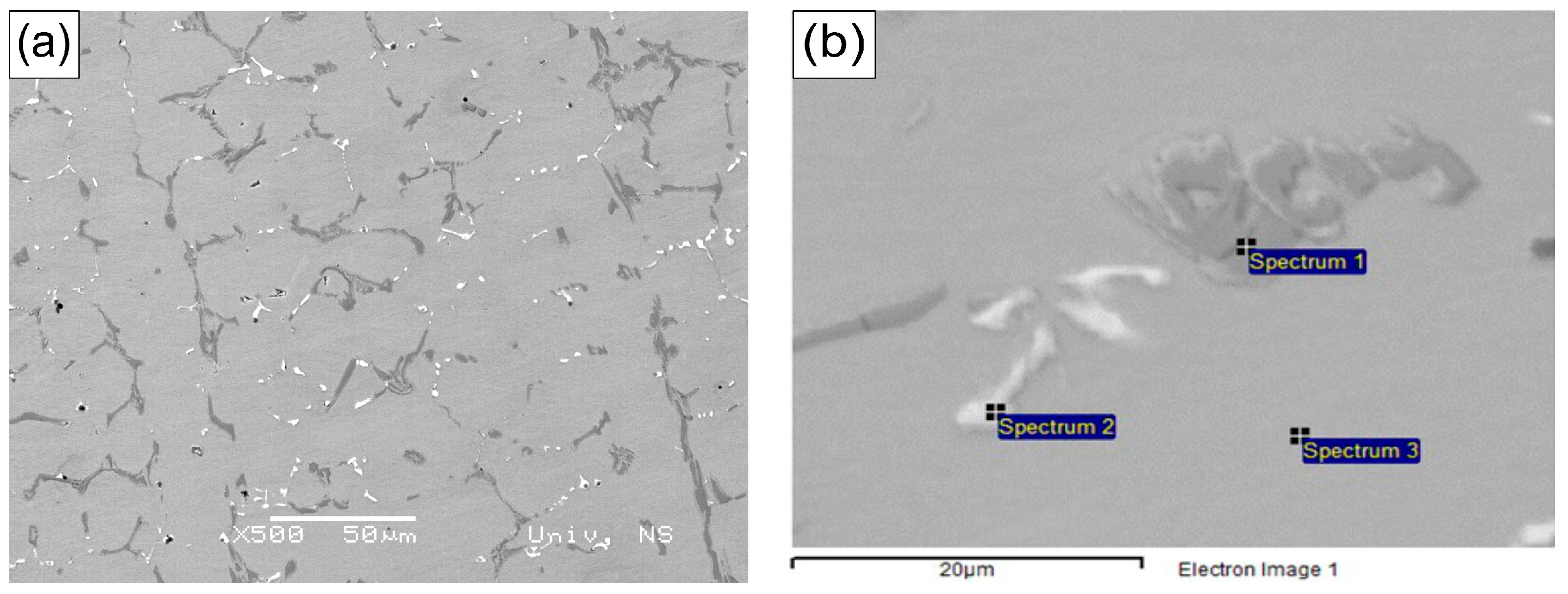
The microstructure of the as-cast alloy has a dendrite morphology with an austenitic matrix and a network of skeleton-shaped eutectic primary carbides located at the grain boundaries and between dendrites (Figure 1a). At higher magnification, according to the BSE intensity contrast, the presence of two types of second-phase particles of different morphology may be seen at the grain boundaries (Figure 1b). As can be seen in Figure 1b, one is a niobium-rich phase (white phase) having laminar-type (or skeleton form) features, whereas the other is a chromium-rich phase (dark gray phase) having fine particle-like features [18].
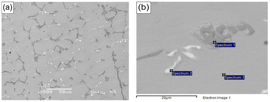
Figure 1.
Microstructure of the HP40Nb alloy as cast. (a) SEM (BSE) microscopy at low magnification (500×); (b) SEM-EDS (BSE) image at high magnification (2000×).
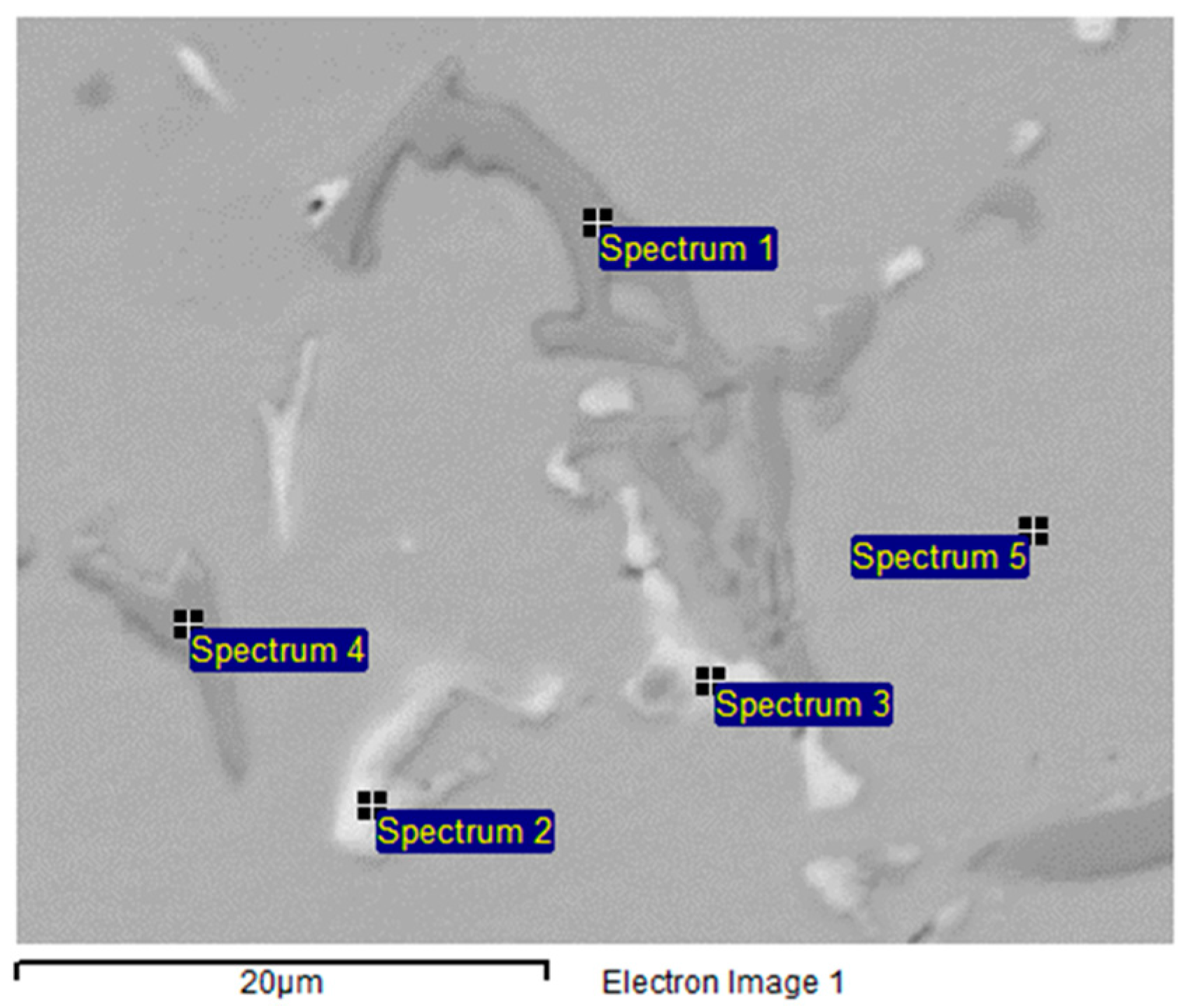
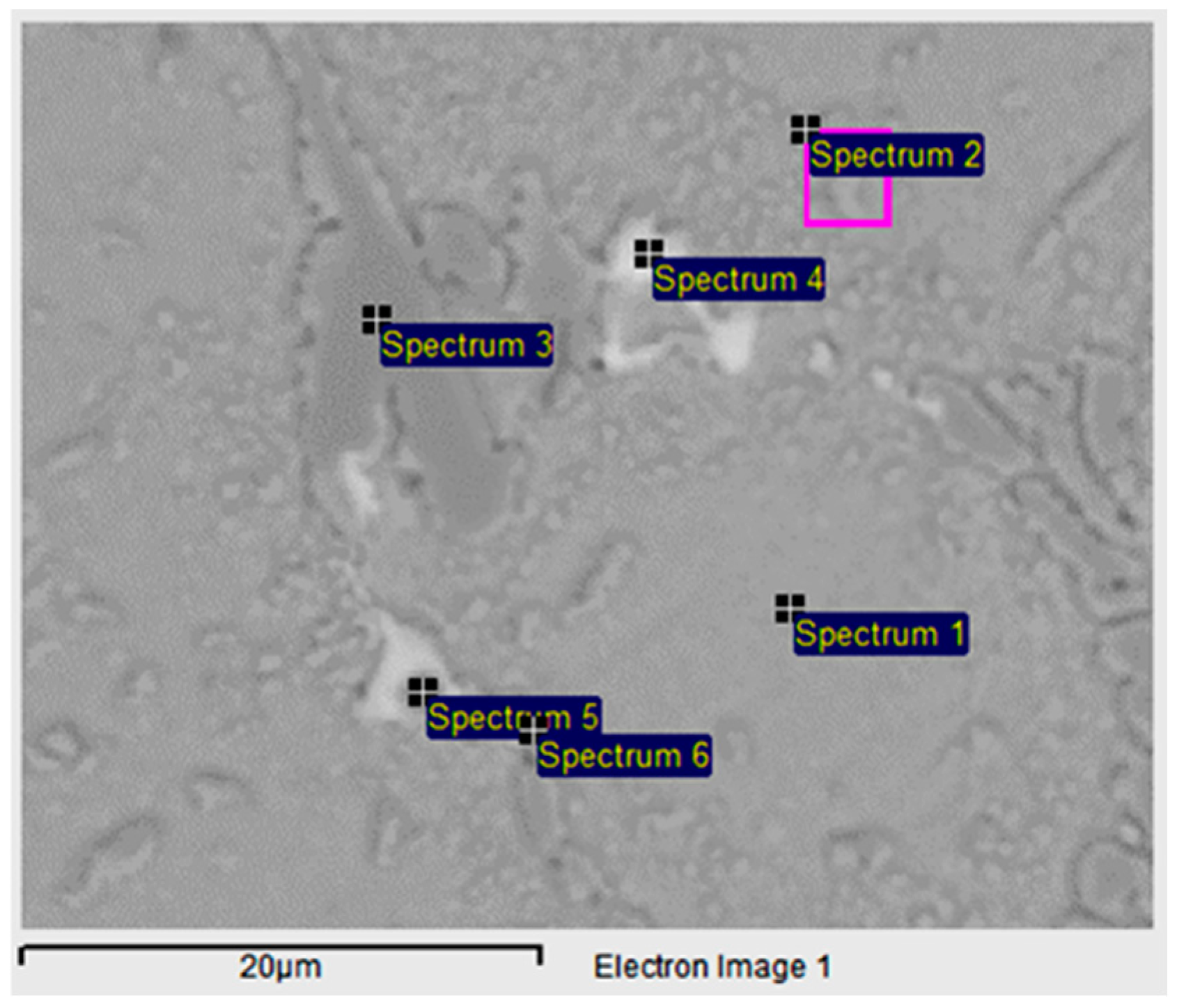
Figure 2 shows an SEM (BSE) micrograph of the HP40Nb alloy in the as-cast condition. As seen in Figure 2, the microstructure consists of an austenitic matrix and a network of primary carbides with two types present: MC carbides (M = Nb, Ti), mainly NbC in white, and M7C3 carbides (M = Cr, Ni, Fe) in dark gray.

Figure 2.
SEM-EDS (BSE) image of phases present in the as-cast HP40Nb alloy.
The chemical composition of the phases present in the HP40Nb alloy, as observed in Figure 2, is shown in Table 1.

Table 1.
Chemical composition of the phases present in the HP40Nb alloy, corresponding to Figure 2.
Two distinct phases were identified: a niobium-rich phase, corresponding to the bright particles in Figure 2 (Spectra 2 and 3), and a chromium-rich phase, corresponding to the dark particles (Spectra 1 and 4). Furthermore, it has been noted that the two varieties of carbides exhibit different morphological characteristics. Carbides in the inter-dendritic boundaries appear as lamellar or skeleton forms. The M7C3 types show the morphological characteristics of a eutectic composite, while the MC types have a more regular morphology [33]. The niobium-rich carbides are more stable at high temperatures compared with the secondary chromium carbides [14].
3.2. XRPD Analysis
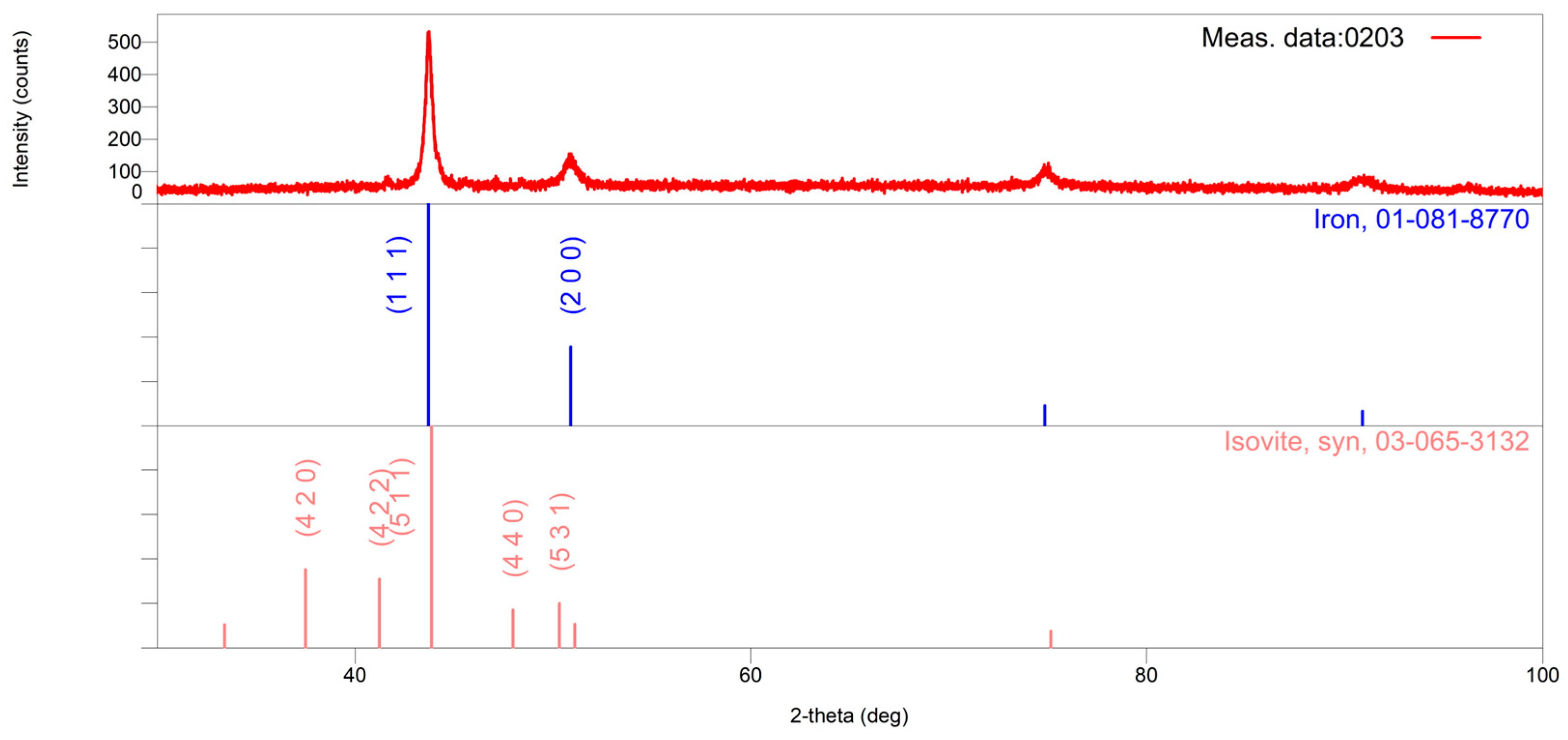
In the as-cast tube sample, the following two major crystal phases are identified: γ-Fe, whose diffraction pattern corresponds to the standard PDF # 01-081-8770, and Cr23C6, whose diffraction pattern corresponds to the standard PDF # 03-065-3132. However, two minor crystal phases in the amount of a few percent could be noticed: Cr7C3, whose diffraction pattern corresponds to the standard PDF # 01-071-3789, and Nb3Ni2Si, whose diffraction pattern corresponds to the standard PDF # 01-072-2171 (PDF-2 Release 2016 RDB), Figure 3. The results of the submitted chemical analysis indicate the possibility of multiple atomic replacements in the abovementioned crystal structures. The stated formulas of the crystal phases should be considered as approximate chemical formulas, i.e., M23C6 instead of Cr23C6, where M = Cr, Fe, Ni, Nb. This is in agreement with the unit cell parameters being significantly different from the standard values for γ-Fe and Cr23C6 (Table 2).
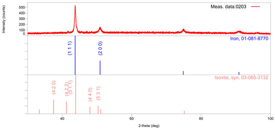
Figure 3.
The X-ray powder pattern of the as-cast sample is shown in red. In the lower part of the graphic, vertical lines show the positions and intensities of the standard reflections of the abovementioned crystal phases (taken from the PDF database) and the numbers of the corresponding cards. In the first row, the positions and intensities of γ-Fe reflections are shown in blue; in the second row, the positions and intensities of M23C6 reflections are shown in pink.
Table 2.
Unit cell parameters of significantly present crystalline phases in the as-cast sample.
In the 950 °C/2 h sample, the following crystalline phases were identified: Cr18.93Fe4.07C6, whose diffraction pattern corresponds to the PDF standard #01-078-1501; NbC, corresponding to the PDF standard #01-074-1222; Cr2O3, corresponding to the PDF standard #01-073-4336; and Nb3Cr4Si5, corresponding to the PDF standard #01-089-2262 (PDF-2 Release 2016 RDB), as shown in Figure 4.

Figure 4.
The XRPD pattern of the 950 °C/2 h sample is shown in red. In the lower part of the graphic, vertical lines show the positions and intensities of the standard reflections of the abovementioned crystal phases (taken from the PDF database) and the numbers of the corresponding cards.
The results of the chemical analysis provided indicate the possibility of multiple atomic substitutions within these crystalline structures. The formulas given for the crystalline phases should be considered approximate chemical formulas; for example, M23C6 instead of Cr23C6 for the carbide phase. This is in agreement with the unit cell parameters being significantly different from the standard values for NbC and M23C6 (Table 3).
Table 3.
Unit cell parameters of significantly present crystalline phases in the 950 °C/2 h sample.
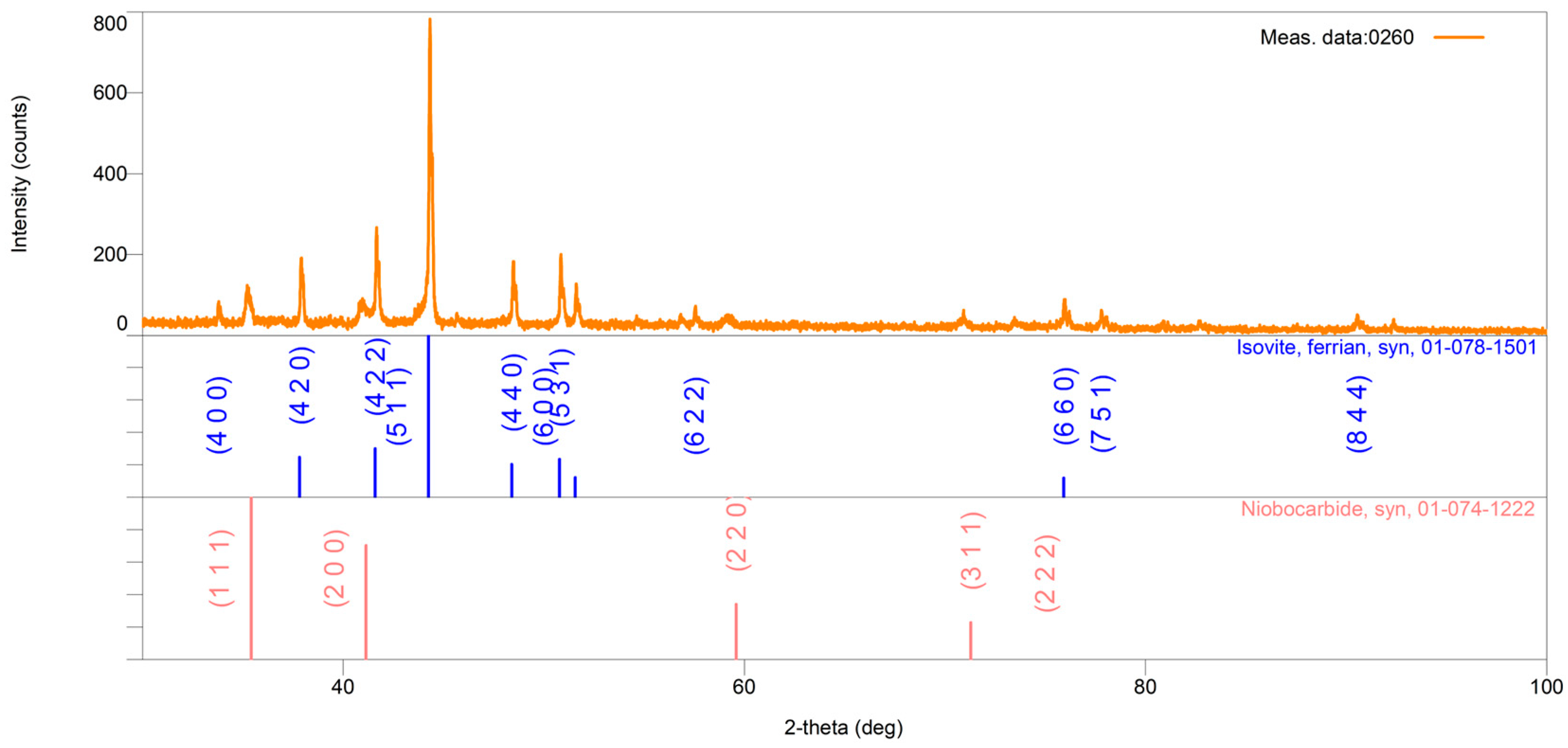
Figure 5 displays the XRPD pattern obtained from the reformer tube sample after being overheated at 950 °C for 8 h. In the reformer tube sample, the following crystal phases are identified: Cr18.93Fe4.07C6, whose diffraction pattern corresponds to the standard PDF#, and 01-078-1501 NbC, whose diffraction pattern corresponds to the standard PDF# 01-074-1222 (PDF-2 Release 2016 RDB) (Figure 5). The results of the submitted chemical analysis indicate the possibility of multiple atomic replacements in the abovementioned crystal structures.
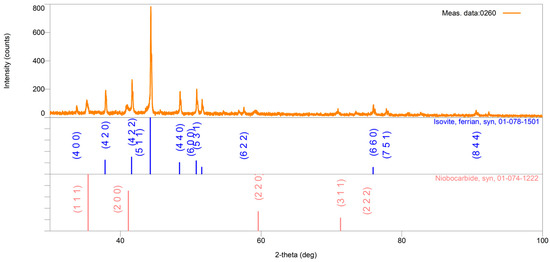
Figure 5.
The XRPD pattern of the 950 °C/8 h sample is shown in orange. In the lower part of the graphic, vertical lines show the positions and intensities of the standard reflections of the abovementioned crystal phases (taken from the PDF database) and the numbers of the corresponding cards. In the first row, the positions and intensities of Cr18.93Fe4.07C6 reflections are shown in blue; in the second row, the positions and intensities of NbC reflections are shown in pink.
The given formulas of crystalline phases should be considered as approximate chemical formulas; for example, for the carbide M23C6 instead of Cr23C6.
The unit cell parameters a (Å) of the notable crystalline phases present in the investigated 950 °C/8 h samples are displayed in Table 4.
Table 4.
Unit cell parameters of significantly present crystalline phases in the 950 °C/8 h sample.
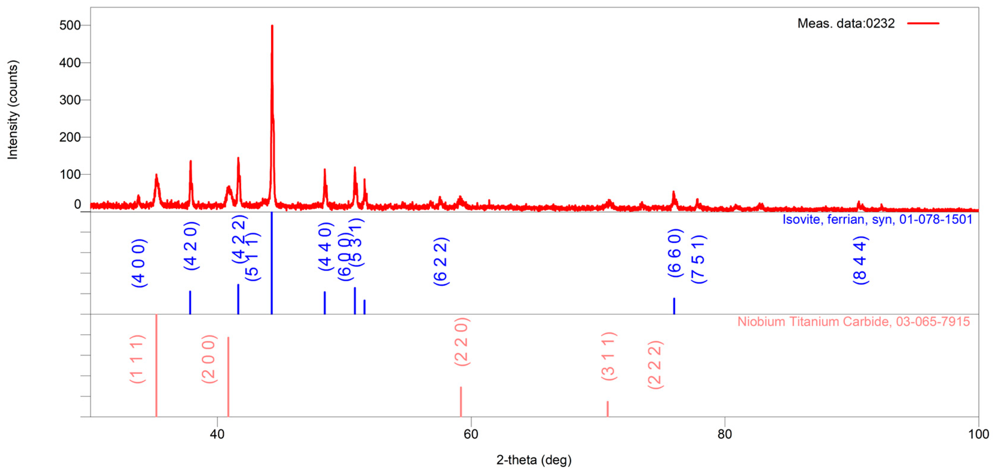
Figure 6 shows the XRPD pattern of the reformer tube sample after overheating at 1050 °C for 2 h. The identified crystal phases include Cr18.93Fe 4.07C6, with a diffraction pattern matching the standard PDF#01-078-1501, and Nb0.9Ti1.1C2, corresponding to the standard PDF#03-065-7915.
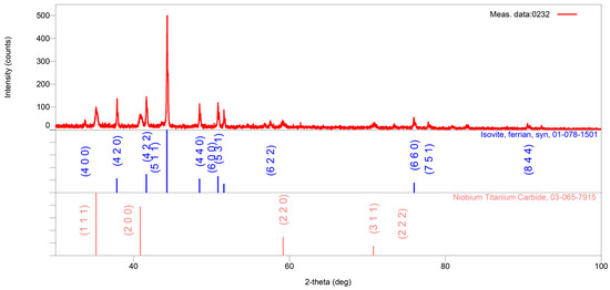
Figure 6.
The X-ray powder pattern of the 1050 °C/2 h sample is shown in red. In the lower part of the graphic, vertical lines show the positions and intensities of the standard reflections of the abovementioned crystal phases (taken from the PDF database) and the numbers of the corresponding cards. In the first row, the positions and intensities of Cr18.93Fe4.07C6 reflections are shown in blue; in the second row, the positions and intensities of Nb0.9Ti1.1C2 reflections are shown in pink.
The results of the submitted chemical analysis indicate the possibility of multiple atomic replacements in the abovementioned crystal structures.
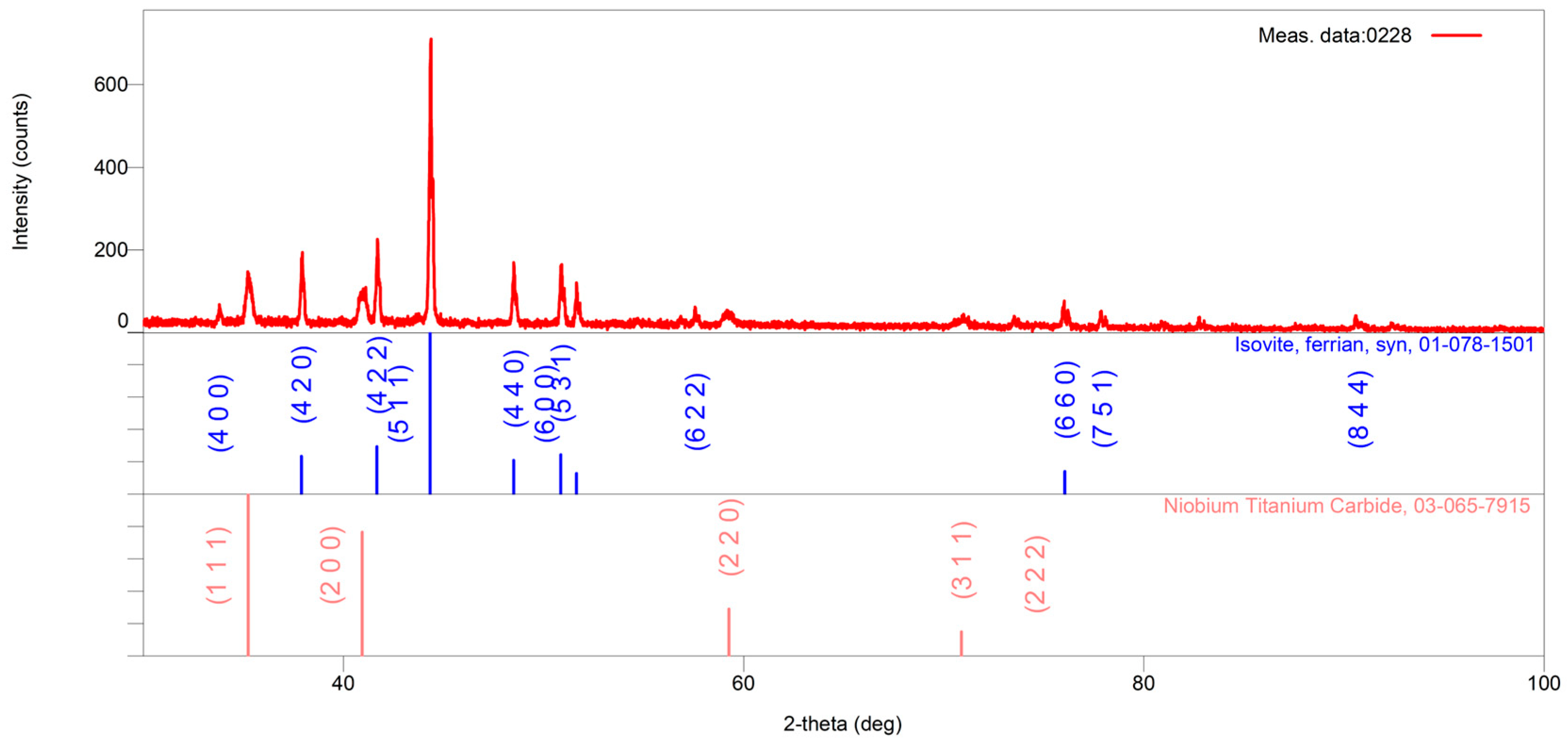
Figure 7 presents the XRPD pattern of the reformer tube sample after overheating at 1050 °C for 8 h. The identified crystal phases in the sample include Cr18.93Fe4.07C6, with a diffraction pattern matching the standard PDF#01-078-1501, and Nb0.9Ti1.1C2, corresponding to the standard PDF#03-065-7915.
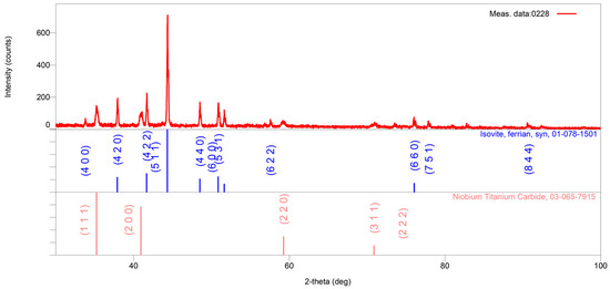
Figure 7.
The X-ray powder diffraction pattern of the sample heat-treated at 1050 °C for 8 h is shown in red. Standard reflection positions and intensities for the identified crystalline phases, obtained from the PDF database, are indicated by vertical lines in the lower part of the figure along with their corresponding card numbers. Reflections for Cr18.93Fe4.07C6 are displayed in blue (top row), while those for Nb0.9Ti1.1C2 are shown in pink (bottom row).
The submitted chemical analysis results indicate the possibility of multiple atomic replacements in the abovementioned crystal structures.
Figure 7 presents the XRPD pattern of the reformer tube sample after overheating at 1050 °C for 8 h. The identified crystal phases in the sample include Cr18.93Fe4.07C6, with a diffraction pattern matching the standard PDF#01-078-1501, and Nb0.9Ti1.1C2, corresponding to the standard PDF#03-065-7915.
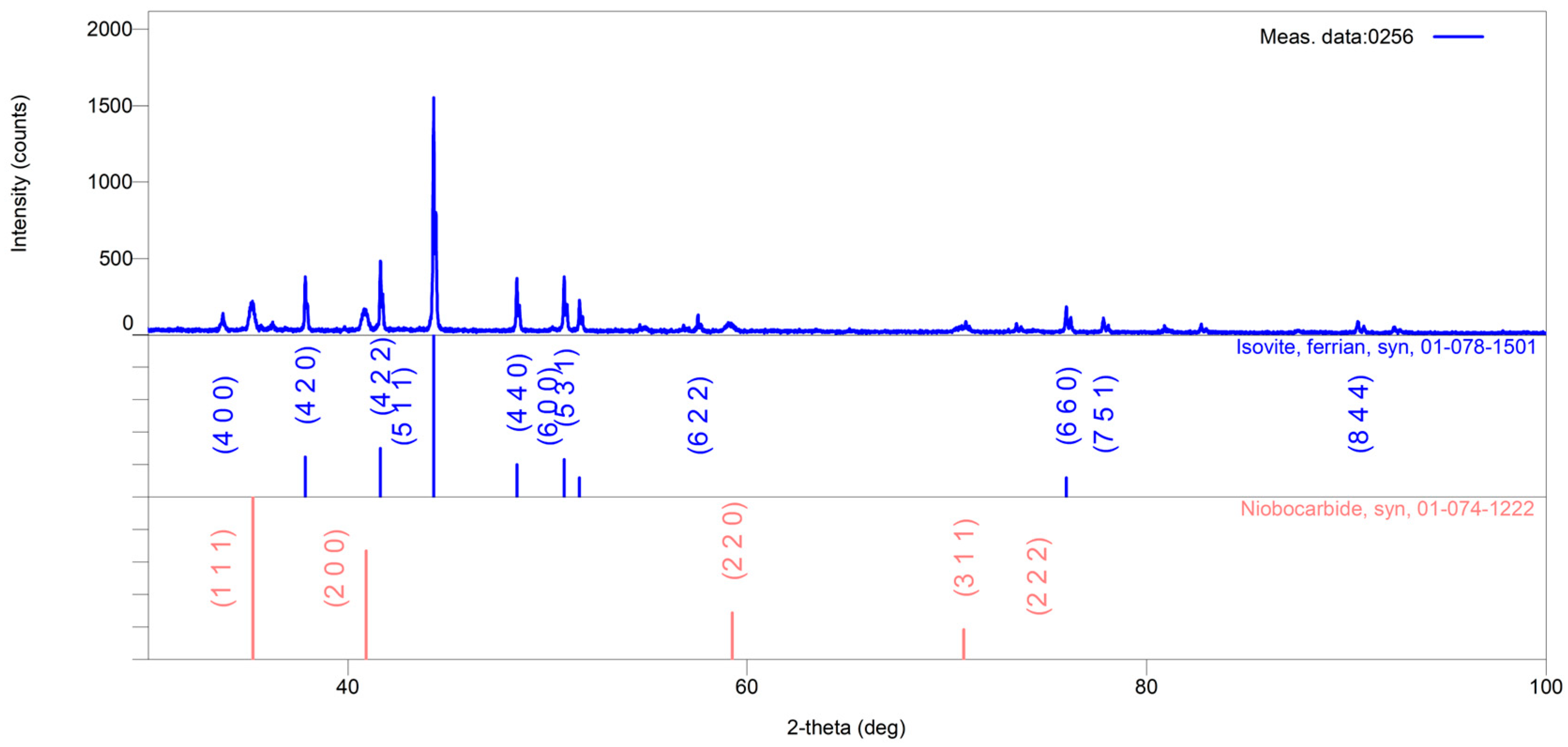
The X-ray powder patterns of extracted powder of samples of the HP40Nb alloy after aging at 1150 °C for 2 and 8 h are shown in Figure 8 and Figure 9, respectively.
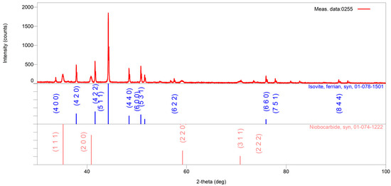
Figure 8.
The X-ray powder pattern of the 1150 °C/2 h sample is shown in red. In the lower part of the graphic, vertical lines show the positions and intensities of the standard reflections of the abovementioned crystal phases (taken from the PDF database) and the numbers of the corresponding cards. In the first row, the positions and intensities of Cr18.93Fe4.07C6 reflections are shown in blue; in the second row, the positions and intensities of NbC reflections are shown in pink.

Figure 9.
The X-ray powder pattern of the 1150 °C/8 h sample is shown in blue. In the lower part of the graphic, vertical lines show the positions and intensities of the standard reflections of the abovementioned crystal phases (taken from the PDF database) and the numbers of the corresponding cards. In the first row, the positions and intensities of Cr18.93Fe4.07C6 reflections are shown in blue; in the second row, the positions and intensities of NbC reflections are shown in pink.
In case of overheating for 2 h (1150 °C/2 h), the identified phases correspond to the complex Cr18.93Fe4.07C6 carbide of the M23C6-type (blue line) and to the NbC carbide (pink line), while after exposure for 8 h (1150 °C/8 h), the same phases (Cr18.93Fe4.07C6 and NbC) were also identified.
3.3. Microstructure After 2 h of Overheating Treatment
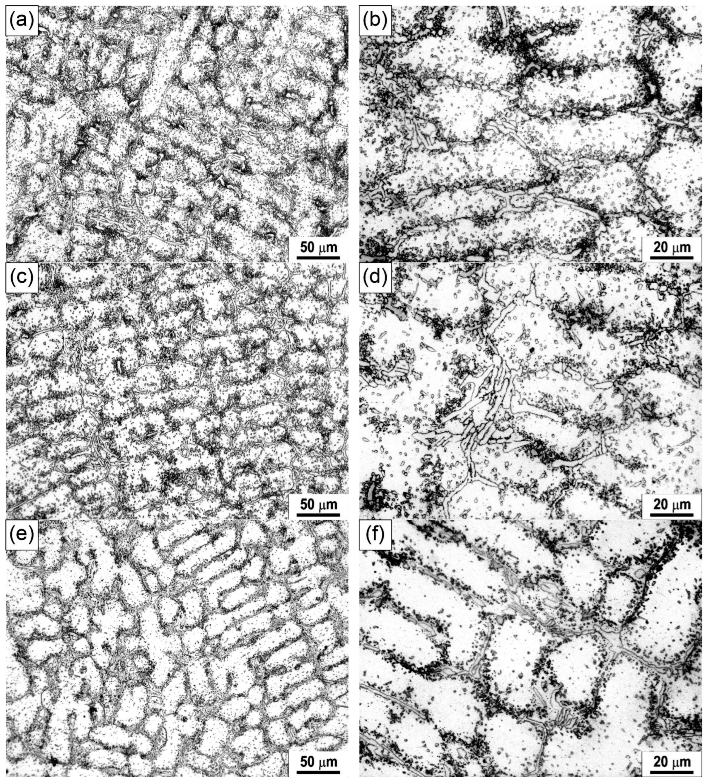
Figure 10 presents representative optical micrographs (LM) illustrating the microstructure of the sample after being overheated at 950 °C, 1050 °C, and 1150 °C for 2 h.
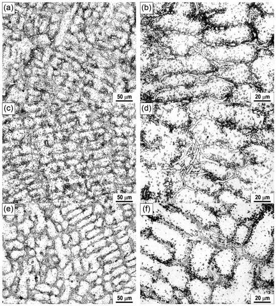
Figure 10.
Light micrographs of the HP40Nb alloy after being overheated at (a,b) 950 °C, (c,d) 1050 °C and (e,f) 1150 °C for 2 h.
As illustrated in Figure 10a,b, the microstructure has experienced considerable changes following overheating at a temperature of 950 °C for 2 h. Its microstructure comprises an austenitic dendritic matrix with a discontinuous network of skeletal-like primary carbides along the grain boundaries and secondary precipitates within the grains. Many secondary carbides were precipitated in the austenitic matrix near the primary carbides and the inter-dendritic region.
Figure 11 illustrates that the microstructure experienced significant changes after overheating at 950 °C, while Table 5 presents the EDS analysis results of the phases in the sample treated at 950 °C for 2 h, as observed in the SEM micrograph in Figure 11.
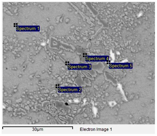
Figure 11.
SEM micrograph of the HP40Nb alloy after being overheated at 950 °C/2 h.
Table 5.
Chemical composition of the phases present in the HP40Nb alloy, corresponding to Figure 11.
The microstructure consists of an austenitic matrix (Spectra 1, 2, and 3) and two types of carbides: niobium-rich carbides (white phase, Spectrum 5) and chromium-rich carbides (dark gray phase, Spectrum 4). On the basis of Figure 10a,b and Figure 11, as well as Table 5, the dark carbides are identified as the M23C6 type (M = Cr) and the light carbides as the MC type (M = Nb), with traces of niobium–chromium–nickel silicide (Nb3Ni2Cr2Si6) and chromium oxide (Cr2O3) also present.
Figure 10c,d show the microstructure of the sample after overheating at 1050 °C for 2 h. The microstructure consists of an austenitic dendritic matrix and a discontinuous network of primary skeletal-shaped carbides located along the dendrite boundaries. Table 6 provides the EDS analysis results of the phases in the sample treated at 1050 °C for 2 h, as observed in the SEM micrograph in Figure 12.
Table 6.
Chemical composition of the phases present in the HP40Nb alloy, corresponding to Figure 12.

Figure 12.
SEM micrograph of the HP40Nb alloy after being overheated at 1050 °C/2 h.
The microstructure consists of an austenitic matrix (Spec. 1) and two types of precipitates: one rich in Nb (white phase, Spec. 6) and one rich in Cr (dark gray phase, Spec. 3, 4, and 5).
A large amount of secondary carbides has precipitated in the austenitic matrix near the primary carbides and the zones around the dendrite boundaries. According to Figure 10c,d, and Figure 12 and Table 6, it can be observed that the primary chromium carbides completely transformed from M7C3 to M23C6. Secondary carbides are detected within the austenitic matrix near the primary carbides. It is important to note that a small quantity of acicular carbides M23C6 (M = Cr, Ni, Fe) was formed in the austenite matrix. Additionally, the amount of precipitated secondary carbides increased with the increase in the superheating temperatures up to 1050 °C.
Figure 10e,f show the microstructure of the sample after overheating at 1150 °C for 2 h. Following this thermal treatment, the quantity of secondary carbides in the austenitic matrix and around the primary carbides was significantly reduced. The microstructure consists of an austenitic dendritic matrix and a discontinuous network of primary skeletal-shaped carbides located along the dendrite boundaries. The primary carbides have coagulated and merged. A significant amount of fine secondary carbides is present in the austenitic matrix near the primary carbides, while carbide-free zones have appeared in the inter-dendritic regions. Although the quantity of secondary carbides has decreased, their coarsening is evident [34]. Table 7 provides the EDS analysis results of the phases in the sample treated at 1150 °C for 2 h, as observed in the SEM micrograph in Figure 13. As a result of overheating at 1150 °C for 2 h, globular secondary carbides have formed in the inter-dendritic zones. On the basis of Figure 12 and Figure 13, it can be concluded that increasing the temperature from 1050 °C to 1150 °C did not affect the type of carbides present in the microstructure.
Table 7.
Chemical composition of the phases present in the HP40Nb alloy, corresponding to Figure 13.
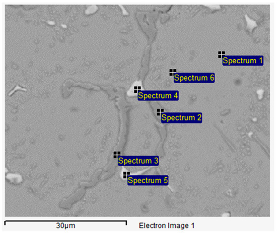
Figure 13.
SEM micrograph of the HP40Nb alloy after being overheated at 1150 °C/2 h.
3.4. Microstructure After 8 h of Overheating Treatment
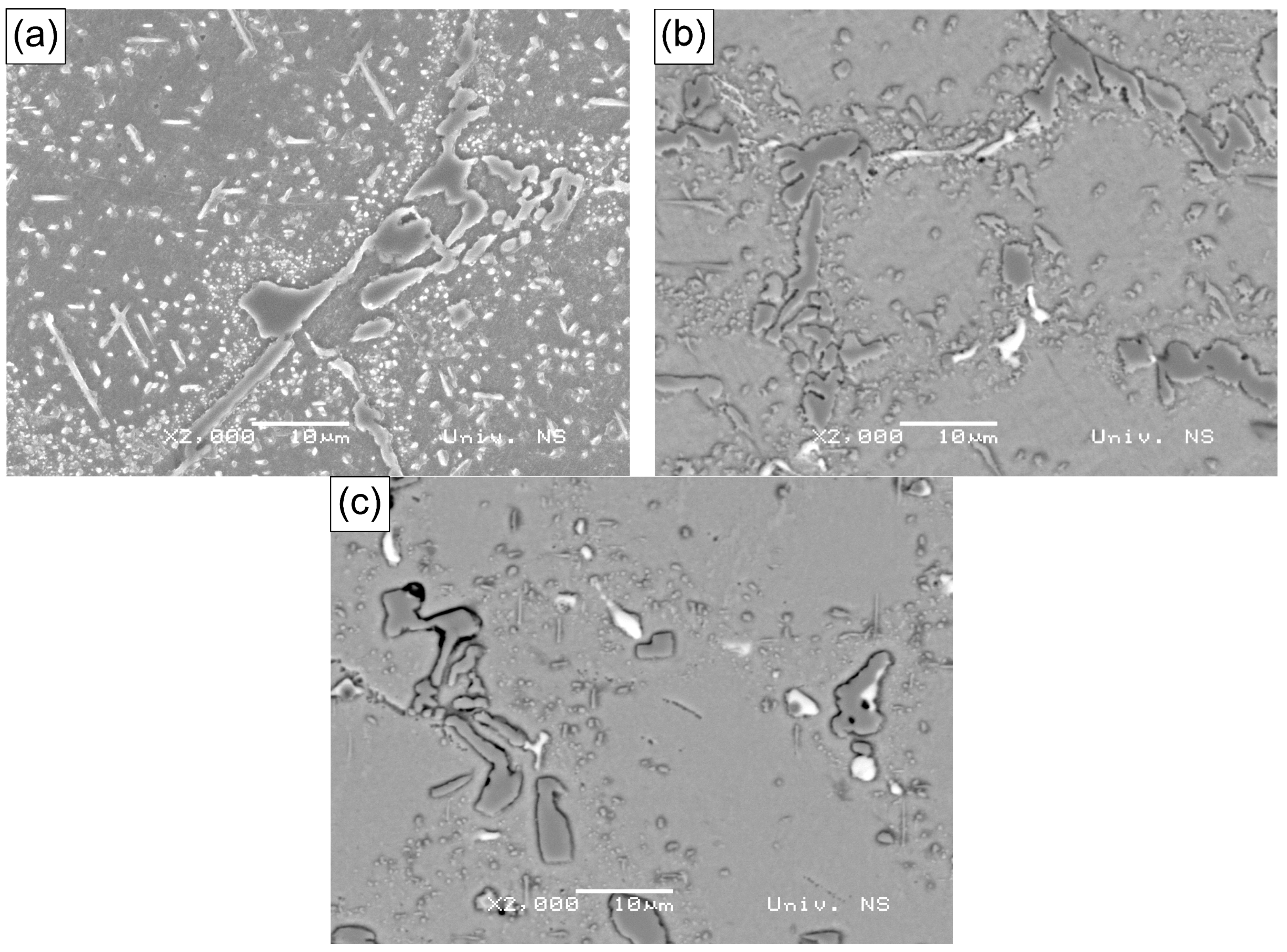
Figure 14a–c illustrate the microstructure of the material obtained after overheating at 950 °C, 1050 °C, and 1150 °C for 8 h.
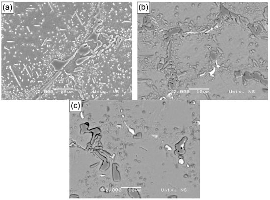
Figure 14.
SEM micrographs of the HP40Nb alloy after being overheated at (a) 950 °C (SE), (b) 1050 °C (BSE) and (c) 1150 °C (BSE) for 8 h.
Figure 14a shows the microstructure of the HP40Nb alloy after overheating at 950 °C for 8 h. The microstructure consists of an austenitic dendritic matrix and a discontinuous network of primary skeletal-shaped carbides located along the dendrite boundaries. A large amount of secondary carbides has precipitated within the dendrites.
Figure 14b shows the microstructure of the HP40Nb alloy after overheating at 1050 °C for 8 h. A large amount of fine secondary carbides has precipitated near the primary carbides located along the dendrite boundaries. Compared with the as-cast microstructure, a finer grain structure is observed, with carbides dissolved along the austenitic grain boundaries. Unlike the as-cast structure on the boundary of primary austenitic grains, a large number of tiny carbides are present, which may be the result of the dissolution of massive carbides on the boundary and carbide islands inside the grain, as indicated in some data in the literature [4,34].
Figure 14c shows the microstructure of the HP40Nb alloy after overheating at 1150 °C for 8 h. A small amount of secondary carbides can be observed in the austenitic matrix. For samples overheated for 8 h, the increase in overheating temperature led to the dissolution of secondary carbides in the inter-dendritic region, followed by the dissolution of carbides near the primary carbides along the dendrite boundaries. On the basis of Figure 15, Figure 16 and Figure 17, it can be observed that the primary chromium carbides (M7C3) transformed into M23C6-type carbides [35,36,37,38,39,40,41]. Secondary carbides were detected within the austenitic matrix near the primary carbides (Figure 15).
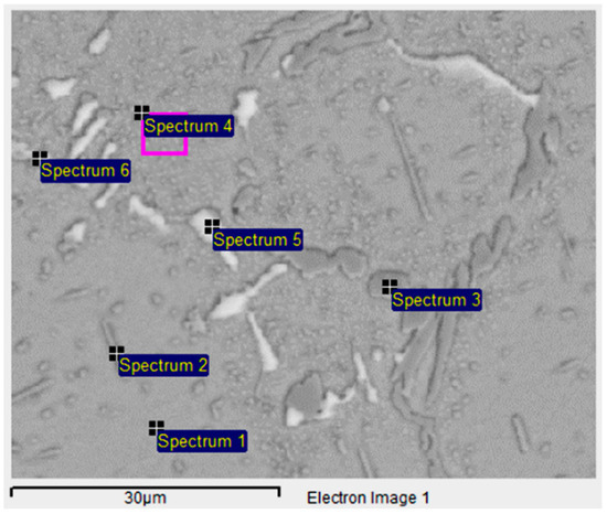
Figure 15.
SEM-EDS (BSE) micrograph of the HP40Nb alloy after being overheated at 950 °C/8 h.
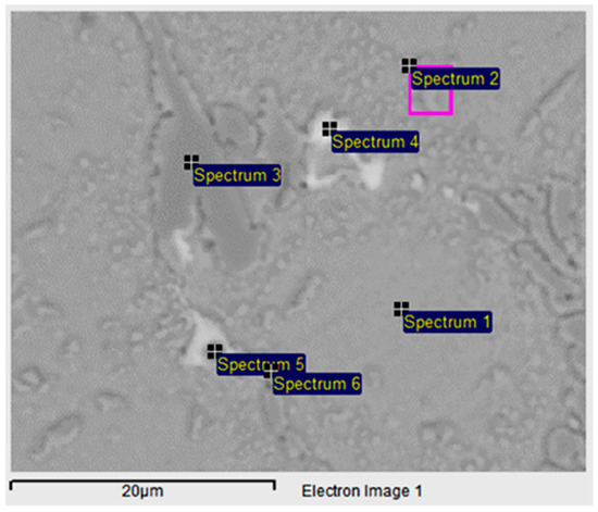
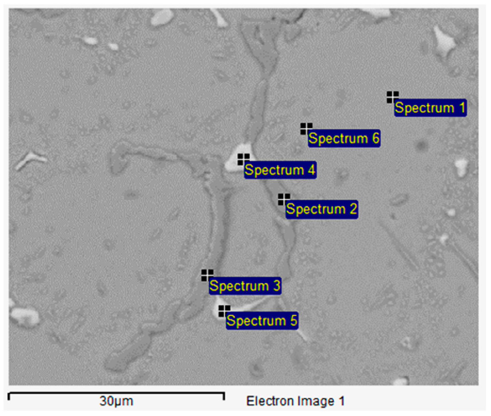
Figure 16.
SEM-EDS (BSE) micrograph of the HP40Nb alloy after being overheated at 1050 °C/8 h.

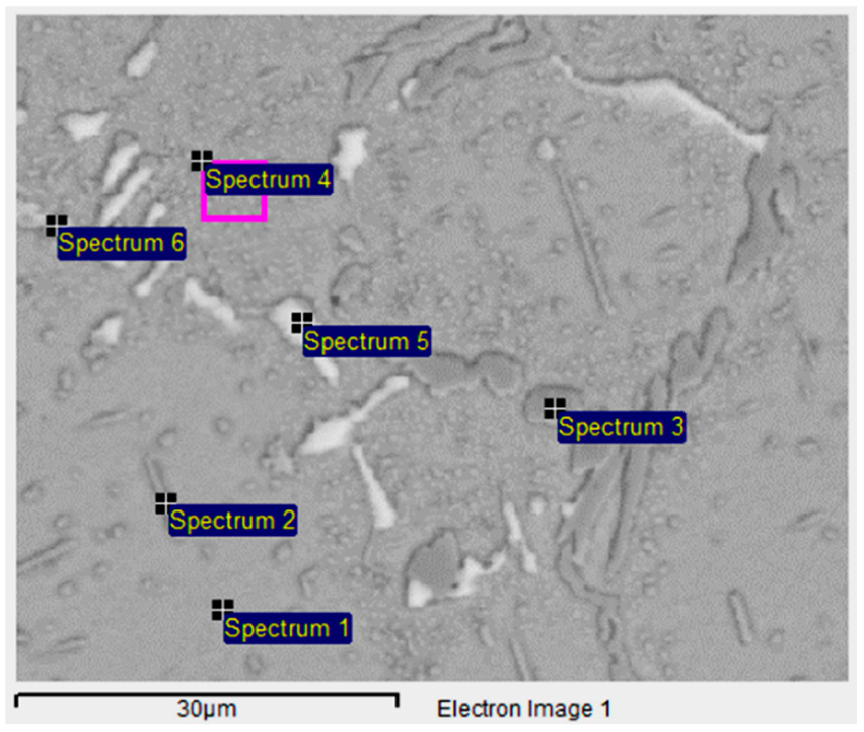
Figure 17.
SEM-EDS (BSE) micrograph of the HP40Nb alloy after being overheated at 1150 °C/8 h.
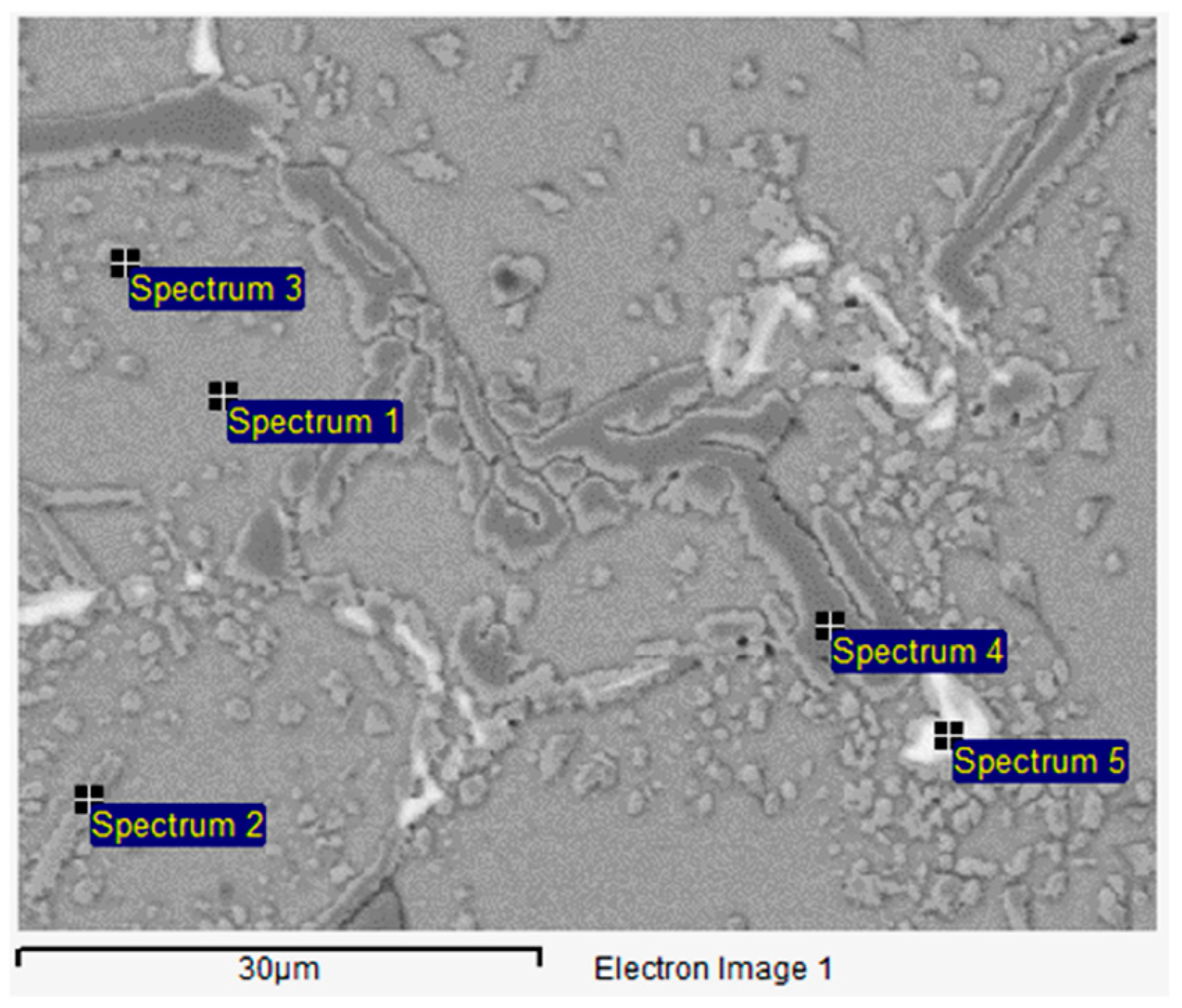
It should be noted that the amount of M23C6-type secondary carbides (M = Cr) formed in the austenitic matrix increased with the increase in overheating temperature to 1050 °C [42], followed by a decrease in the amount of secondary carbides. Secondary carbides precipitate in the austenitic matrix up to a temperature of 1050 °C [19], after which, they undergo partial dissolution (near the primary carbides) or complete dissolution within the dendrites. This change can be observed in detail in SEM Figure 15, Figure 16 and Figure 17 and in the corresponding EDS Table 8, Table 9 and Table 10, respectively.
Table 8.
Chemical composition of the phases present in the HP40Nb alloy, corresponding to Figure 15.
Table 9.
Chemical composition of the phases present in the HP40Nb alloy, corresponding to Figure 16.
Table 10.
Chemical composition of the phases present in the HP40Nb alloy, corresponding to Figure 17.
Table 8 provides the EDS analysis results of the phases in the sample treated at 950 °C for 8 h, as observed in the SEM micrograph in Figure 15.
The chemical composition (at%) of the phases present in the HP40Nb alloy after being overheated at 1050 °C for 8 h, as observed in Figure 16, is given in Table 9.
Table 10 provides the EDX analysis results of the sample treated at 1150 °C for 8 h, as observed in the SEM micrograph in Figure 17.
Table 11 presents the alloy hardness test results, including the average hardness for each trial. The hardness measurements of the specimens, following overheating treatment at 950, 1050, and 1150 °C, reveal an increase in hardness compared with the initially received specimen. The hardness of the as-received alloy was 215 HV10. The hardness value reached its maximum of 232 HV10 after 8 h at a temperature of 1050 °C. Extending the overheating time from 2 h to 8 h at 1150 °C resulted in an increase in hardness from 207 to 232 HV10.
Table 11.
The hardness values of the alloy HP40Nb in its initial state and after overheating at 950, 1050, and 1150 °C for 2 and 8 h, respectively.
The hardness results are consistent with those reported by other authors [18].
Additionally, Table 11 indicates that the highest hardness values were recorded in specimens subjected to overheating for 8 h.
4. Discussion
The microstructure of the as-received alloy consists of primary carbide networks dispersed within an austenitic matrix, as presented in Figure 1. The dendritic morphology is indicative of a typical cast microstructure. Notably, no secondary carbide formation was observed, as shown in Figure 2. SEM analysis further revealed that the primary carbide networks can be distinguished into two distinct phases, which exhibit dark and bright contrast. As illustrated in Figure 1, the Cr-rich phases identified in the microstructure primarily correspond to M23C6 and M7C3 carbides, while the Nb-rich precipitate is characterized as NbC carbide. According to previous investigations [35,43,44], niobium preferentially reacts with carbon during solidification at elevated temperatures, leading to the formation of NbC, with the Nb-to-C atomic ratio playing a crucial role in driving its precipitation. In the present study, the relatively low Nb-to-C ratio (0.2) was insufficient to fully incorporate all available free carbon into NbC [35]. As a result, the remaining carbon in the matrix was preferentially bound by chromium, promoting the formation of Cr-rich carbides at lower solidification temperatures. Due to the high cooling rate, the complete transformation of M7C3 into M23C6 was inhibited.
The overheating temperature is an important factor that affects the morphology of carbides. On one hand, irregularly shaped carbides at the grain boundaries hinder the sliding of grain boundaries, while intragranular carbides prevent dislocation movement on the other hand. The precipitation of secondary carbides leads to a reduction in the carbon atom content in the matrix and decreases the effect of solid solution strengthening. During carbide precipitation, the ability of carbides to block dislocation slips is reduced. The morphology of carbides is an important factor influencing the creep properties of the HP40Nb alloy [42,45,46].
In comparison with the microstructure in its initial state, the microstructure of the HP40Nb alloy after overheating at 950 °C for 2 h (Figure 10b) exhibits a markedly higher concentration of carbide in the austenitic region adjacent to the secondary carbide and within the austenitic matrix in the inter-dendritic region. Primary carbides with lamellar and plate-like morphologies are observed along the dendrites, forming discontinuous chains. Additionally, a significant amount of finely precipitated secondary carbides is visible within the austenitic matrix and near the boundaries of the dendrites. On the basis of the XRPD pattern presented in Figure 4, the Cr-rich carbide is identified as an M23C6-type carbide, whereas the Nb-rich phase is classified as an NbC phase.
At an overheating temperature of 1050 °C, in addition to secondary carbides, a quantity of needle-like M23C6 type carbides (where M = Cr, Ni, Fe) was formed within the austenite matrix. The amount of secondary carbides increased as the overheating temperature rose to 1050 °C.
The results of the microstructure analysis of the HP40Nb alloy after overheating at 1050 °C for 2 h are consistent with the findings of Sourmail [27], Fuyang et al. [41], and the work of Martin C. H. Tse [31]. Fuyang et al. [41] also observed the transformation of M7C3-type carbides into M23C6 due to the exposure of the HP40Nb alloy to temperatures ranging from 700 to 990 °C for 1 to 6000 h. This transformation is driven by the thermodynamic instability of M7C3 at elevated temperatures, resulting in its dissolution and the subsequent precipitation of the more stable M23C6 phase. Furthermore, Tse’s research [31] offers valuable insights into the metallurgical advancements in reformer tube alloys, which further enhance the understanding of carbides’ evolution under high-temperature conditions.
Liu et al. [17] analyzed the changes in the microstructure and mechanical properties of the HP40Nb alloy during aging at 900 °C from 0 to 2016 h and observed the transformation of M7C3-type carbides into M23C6-type carbides.
Almeida et al. [42] studied the influence of niobium content on the microstructural changes in the HP40Nb alloy after aging at 700, 900, and 1100 °C for 1000 h and also observed the transformation of M7C3-type carbides into M23C6-type carbides. Wang et al. [35] investigated the effect of overheating the HP40Nb alloy at temperatures ranging from 900 to 1250 °C for 100 h on its microstructure and observed the transformation of M7C3-type carbides into M23C6-type carbides.
Zones without secondary carbides appeared in the inter-dendritic space (Figure 10c,d). Near the primary carbides are many finely dispersed secondary carbides in the austenitic matrix.
The quantity of secondary carbides diminished, but their coarsening is evident [34]. Overheating at a temperature of 1150 °C for 2 h resulted in the formation of globular-shaped secondary carbides that separated the regions between the dendrites.
Fuyang et al. [41] also observed the dissolution of secondary carbides with increasing overheating temperature while studying the microstructural changes in the HP series of alloys containing 0.6% C, 1.34% Nb, and Mo during aging at temperatures between 750 and 950 °C across intervals of 1 to 1800 h.
Liu [4] stated that the carbide shape present in the microstructure of the tested material is highly sensitive to the overheating temperature. The overheating of the alloy accelerates the dissolution of smaller carbide particles and the enlargement of larger ones through coagulation, accompanied by morphological changes in carbides that ultimately result in material failure. Coagulation requires a difference in the particle size of the carbide phase, resulting in the solid austenite solution becoming undersaturated and affecting smaller particles under these conditions.
As a result, the smaller particles dissolve, while carbon atoms and alloying elements are transferred via diffusion and incorporated on the surface of the larger particles.
According to the XRPD pattern of the phases present, it can be concluded that the phases present in the original material are the Cr-rich carbide M7C3 and the Nb carbide NbC; after overheating, the phases present in the material are Cr-rich carbide M23C6 and the Nb-rich carbide NbC. The difference between the Cr-rich phase in the original material and the superheated material is that the furnace tube is manufactured using a centrifugal casting process. The cooling rate of the original material is relatively fast during the manufacturing process. The metastable M7C3 carbide that crystallizes first does not have time to be converted into M23C6 carbide. After overheating, the metastable M7C3 carbide becomes stable. The state M7C3 carbide is completely transformed into the stable M23C6 carbide [35]. The phase type, grain size, and degree of dispersion of secondary carbides in the microstructure affect the mechanical properties of the material [20].
The difference between samples in the content of intragranular carbide and the degree of grain boundary carbide coarsening increases with longer superheating times.
After exposure for 8 h at 1050 °C (high temperature), secondary chromium carbides precipitate inside the grains (Figure 14b). The appearance of needles (carbides), indicating carbides (dark gray) with gray edges, white carbides, and small gray carbides at the base, can be noticed in Figure 14c. Fewer secondary carbides are present, and these have solidified. The change in the carbide contents can be attributed to the dynamic equilibrium between the dissolution and growth of carbides and the carbon diffusion.
As the temperature rises to 1150 °C for 8 h, the content of secondary carbides decreases due to carbide dissolution. The appearance of carbide needles becomes noticeable; dark gray carbides with gray edges are evident. Small, tiny white carbides are found at the base (as seen in Figure 14c).
Liu and Chen [17] also reported that the content of inter-dendritic carbides increases with longer aging times at a constant temperature of 900 °C.
Extending the overheating time to 8 h at 1150 °C (Figure 14c) results in a reduction in the quantity of secondary carbides and the formation of carbide-free zones within the microstructure. The results indicate that with a prolonged soaking time, chromium carbide decomposes, and the carbon combines with niobium, leading to an increase in niobium-rich carbides. These findings are consistent with the study by Wang et al. [4], which found that the carbide content decreased at a temperature of 1250 °C.
According to the microstructure results of the HP40Nb alloy samples after all overheating treatments (Figure 10 and Figure 14) and the hardness measurement results (Table 11), it can be concluded that the presence of a large number of secondary carbides in the austenitic matrix contributes to the increased hardness of the alloy, as observed by other authors [39,41].
Lanz et al. [39] investigated the effect of overheating temperatures ranging from 750 to 950 °C over various time intervals (1–1800 h) on a modified HP alloy containing 0.6% S and 1.34% Nb. They observed an increase in the alloy’s hardness after aging due to the precipitation of needle-like secondary carbides. However, as the aging time and temperature increased, the coarsening of these carbides led to a reduction in hardness. Picasso et al. [33] studied a nickel-based alloy subjected to aging treatments at temperatures between 750 and 900 °C for durations of 1000–4000 h. Their research indicated an increase in hardness values due to aging compared with the as-cast state. However, when the aging time exceeded 500 h, the hardness value began to decline.
The maximum hardness observed in the sample treated at 1150 °C for 8 h is attributed to the dissolution of secondary chromium carbides and the diffusion of carbon into the austenitic matrix.
5. Conclusions
The microstructural evolution of the HP40 alloy alloyed with Nb following short-term overheating was investigated. The main conclusions are based on the experimental results observed.
The as-cast microstructure of the HP40Nb alloy consists of an austenitic dendritic matrix strengthened by a network of primary eutectic-like carbides rich in chromium and niobium of the M23C6 and MC types, respectively.
Microstructural analysis of the HP40 alloy micro-alloyed with Nb after short-term overheating at 950 °C for 2 h revealed a significant presence of secondary carbides in the austenite matrix and near the primary carbides.
Exposure to a temperature of 1050 °C for 2 h resulted in a significant quantity of secondary carbides being dispersed and distributed within the austenitic matrix and agglomerated along the grain boundaries. When the overheating time reached 8 h at a temperature of 1050 °C, a finer grain structure was observed, with carbides dissolved along the austenitic grain boundaries.
Increasing the temperature of overheating from 950 °C to 1150 °C resulted in a reduction in secondary carbides within the structure. Additionally, this increase in temperature altered the morphology of the primary carbides, causing them to adopt a spherical shape.
At a higher overheating temperature of 1150 °C, soaking for 2 h yielded a significantly reduced quantity of the secondary carbides within the austenitic matrix and in the surroundings of the primary carbides. Extending the overheating time to 8 h further decreased the number of secondary carbides.
The increase in hardness values is due to the high content of secondary carbides in the austenitic matrix. This increase is also influenced by the dissolution of secondary carbides and the diffusion of carbon within the austenitic structure.
The microstructure studied via the given combination of techniques has provided new insight into how different carbide types and morphologies form during overheating and further highlighted the significance of microstructure control and monitoring in utilization of reformer tubes in extreme conditions.
In general, this research is beneficial, as it provides insights into how short-term high-temperature exposure affects HP40Nb alloys, particularly under real operating conditions.
Author Contributions
Conceptualization, M.T., D.R. and O.E.C.; methodology, O.E.C., P.J., D.R. and A.K.; validation, M.T.; formal analysis, M.R.; investigation, M.T., P.J., A.K. and D.R.; resources, P.J., S.S. and M.R.; data curation, A.K.; writing—original draft preparation, O.E.C. and S.S.; writing—review and editing, D.R., A.K., O.E.C. and P.J.; visualization, M.T. and P.J.; supervision, D.R.; project administration, P.J. and S.S.; funding acquisition, M.R. and S.S. All authors have read and agreed to the published version of the manuscript.
Funding
This work was supported by the Ministry of Science, Technological Development, and Innovation of the Republic of Serbia; Contract No. 451-03-137/2025-03/200108, Faculty of Mechanical and Civil Engineering in Kraljevo, University of Kragujevac; 451-03-136/2025-03/200213, Innovation Centre of the Faculty of Mechanical Engineering, Belgrade, University of Belgrade; 451-03-136/2025-03/200017 through the realization of research theme 1702514 by the “Vinča” Institute of Nuclear Sciences, National Institute of the Republic of Serbia, University of Belgrade; 451-03-137/2025-03/200156 and 01-50/295 by the Faculty of Technical Science, University of Novi Sad; and 451-03-136/2025-03/200126 by the Faculty of Mining and Geology, University of Belgrade, Serbia. The work titled “Insight into the Microstructure Analysis of HP Austenitic Heat-Resistant Steel under Short-Term High-Temperature Exposure” primarily aligns with Sustainable Development Goal (SDG) 9 Industry, Innovation and Infrastructure from the UN’s Agenda 2030.
Data Availability Statement
The original contributions presented in the study are included in the article. Further inquiries can be directed to the corresponding authors.
Conflicts of Interest
The authors declare no conflicts of interest.
References
- ASTM A297/ASTM A297-21a; Standard Specification for Castings, Austenitic, for High Temperature Service. ASTM International: West Conshohocken, PA, USA, 2021.
- Bonaccorsi, L.; Guglielmino, E.; Pino, R.; Servetto, C.; Sili, A. Damage analysis in Fe–Cr–Ni centrifugally cast alloy tubes for reforming furnaces. Eng. Fail. Anal. 2014, 36, 65–74. [Google Scholar] [CrossRef]
- Ilman, M.; Kusmono, N. Analysis of material degradation and life assessment of 25Cr–38Ni–Mo–Ti wrought alloy steel (HPM) for cracking tubes in an ethylene plant. Eng. Fail. Anal. 2014, 42, 100–108. [Google Scholar] [CrossRef]
- Wang, W.Z.; Xuan, F.Z.; Wang, Z.D.; Liu, C.J. Effect of overheating temperature on the microstructure and creep behavior of HP40Nb alloy. Mater. Des. 2011, 32, 4010–4016. [Google Scholar] [CrossRef]
- Tillack, D.J.; Guthrie, J.E. Wrought and Cast Heat-Resistant Stainless Steels and Nickel Alloys for the Refining and Petrochemical Industries; Technical Series; Nickel Development Institute: Toronto, ON, Canada, 1998; Volume 10, pp. 71–85. [Google Scholar]
- Allahkaram, S.R.; Borjali, S.; Khosravi, H. Investigation of weldability and property changes of high-pressure heat-resistant cast stainless steel tubes used in pyrolysis furnaces after a five-year service. Mater. Des. 2012, 33, 476–484. [Google Scholar] [CrossRef]
- Shen, L.M.; Gong, J.M.; Jiang, Y.; Geng, L.Y. Effects of aging treatment on microstructure and mechanical properties of Cr25Ni35Nb and Cr35Ni45Nb furnace tube steel. Acta Metall. Sin. Engl. Lett. 2011, 24, 235–242. [Google Scholar] [CrossRef]
- Nishiyama, Y.; Otsuka, N.; Nishizawa, T. Carburization Resistance of Austenitic Alloys in CH4-CO2-H2 Gas Mixtures at Elevated Temperatures. Corrosion 2003, 59, 688–700. [Google Scholar] [CrossRef]
- Mobaraki, M.; Afshang, B.; Rahimpour, M.R.; Bahrololoom, M.E. Effect of cracking feedstock on carburization mechanism of cracking furnace tubes. Eng. Fail. Anal. 2020, 107, 104216. [Google Scholar] [CrossRef]
- Tawancy, H.M. Degradation of mechanical strength of pyrolysis furnace tubes by high-temperature carburization in a petrochemical plant. Eng. Fail. Anal. 2019, 16, 2171–2178. [Google Scholar] [CrossRef]
- ASTM A608/A608M-20; Standard Specification for Centrifugally Cast Iron-Chromium-Nickel High-Alloy Tubing for High-Temperature Service. ASTM International: West Conshohocken, PA, USA, 2020.
- Lissarrague, M.H.S.; Lanz, C.A. NbC transformation during aging in HP40-Nb heat resistant alloy. Acta Metall. Slovaca 2022, 28, 147–150. [Google Scholar] [CrossRef]
- Timotijević, M.; Erić Cekić, O.; Rajnović, D.; Dojčinović, M.; Janjatović, P. Microstructural evolution and mechanical properties degradation HPNb alloy degradation after eleven year serviced. Struct. Integr. Life 2022, 22, 299–304. [Google Scholar]
- Zhou, Y.; Liu, Y.; Zhou, X.; Liu, C.; Yu, J. Precipitation and hot deformation behavior of austenitic heat-resistant steels: A review. J. Mater. Sci. Technol. 2017, 33, 1448–1456. [Google Scholar] [CrossRef]
- Dessolier, T.; McAuliffe, T.; Hamer, W.J.; Hermse, C.G.M.; Britton, T.B. Effect of high temperature service on the complex through-wall microstructure of centrifugally cast HP40 reformer tube. Mater. Charact. 2021, 177, 111070. [Google Scholar] [CrossRef]
- Ghatak, A.; Robi, P.S. Investigation of Microstructure and Creep Life Analysis of Centrifugally Cast Fe-Cr-Ni Alloy Reformer Tubes. Manuf. Sci. Technol. 2015, 3, 155–159. [Google Scholar] [CrossRef]
- Liu, C.J.; Chen, Y. Variations of the microstructure and mechanical properties of HP40Nb hydrogen reformer tube with time at elevated temperature. Mater. Des. 2011, 32, 2507–2512. [Google Scholar] [CrossRef]
- Timotijević, M.; Erić Cekić, O.; Rajnović, D.; Janatović, P. Microstructural analysis of a HP 40Nb alloy aged. Eng. Today 2022, 1, 41–47. [Google Scholar] [CrossRef]
- Hetzner, D.W.; Geertruyden, W.V. Crystallography and metallography of carbides in high alloy steels. Mater. Charact. 2008, 59, 825–841. [Google Scholar] [CrossRef]
- Skindaras, R.; Valiulis, A.V.; Spychalski, W.L. The structure and mechanical properties of the high chromium and nickel content cast alloy after long duration work in high temperature. MECH 2014, 19, 706–710. [Google Scholar] [CrossRef]
- Kondo, Y.; Sakurai, Y.; Namekata, J.; Tanaka, M.; Hangai, F. Effect of High Temperature Aging on Eutectic Carbide Morphology of Centrifugally Cast HK40 and HP Steels. Tetsu Hagane 1990, 7, 1195–1201. [Google Scholar] [CrossRef]
- Haidemenopoulos, G.N.; Zervaki, A.D.; Kamoutsi, H.; Polychronopoulou, K. Creep rupture in HP-Nb refractory steel tubes due to short-term overheating. Eur. J. Mater. 2021, 1, 1–22. [Google Scholar] [CrossRef]
- Voicu, R.; Eric, A.; Poquillon, D.; Furtado, J.; Lacaze, J. Microstructure evolution of HP40-Nb alloys during aging under air at 1000 °C. Mater. Charact. 2009, 60, 1020–1027. [Google Scholar] [CrossRef]
- Buchanan, K.G.; Kral, M.V.; Bishop, C.M. Crystallography and Morphology of MC Carbides in Niobium-Titanium Modified As-Cast HP Alloys. Metall. Mater. Trans. A 2014, 45, 3373–3385. [Google Scholar] [CrossRef]
- Bettanini, A.M.; Ding, L.; Mithieux, J.D.; Parrens, C.; Idrissi, H.; Schryvers, D.; Delannay, L.; Pardoen, T.; Jacques, P.J. Influence of M23C6 dissolution on the kinetics of ferrite to austenite transformation in Fe-11Cr-0.06C stainless steel. Mater. Des. 2019, 162, 362–374. [Google Scholar] [CrossRef]
- Zhang, J.; Li, J.; Shi, C.; Li, J. Evolution of Eutectic Carbide during M7C3 /M23C6 in situ Transformation in Martensitic Stainless Steel. Steel Res. Int. 2022, 93, 2200231. [Google Scholar] [CrossRef]
- Sourmail, T. Precipitation in creep resistant austenitic stainless steel. Mater. Sci. Technol. 2001, 17, 1–13. [Google Scholar] [CrossRef]
- Nascimento, M.L.C.; da Cruz Gallo, F.; dos Santos Queiroz, F.; Mendes, M.C.; Eckstein, C.B.; Nogueira, L., Jr.; Le May, I.; Ribeiro Pereira, G.; de Almeida, L.H. Effect of short-time overheating in the morphology of primary carbides network in Nb and NbTi-modified HP stainless steels steam reforming tubes. J. Mater. Res. Technol. 2023, 22, 382–392. [Google Scholar] [CrossRef]
- Ma, Y.W.; Yang, G.; Yoon, K.B.; Le, T.G. Microstructure Evaluation During Short Term Creep of Cr35Ni45Nb Cast Alloy Reformer Tube. Met. Mater. Int. 2020, 27, 5165–5172. [Google Scholar] [CrossRef]
- Haidemenopoulos, G.N.; Polychronopoulou, K.; Zervaki, A.D.; Kamoutsi, H.; Alkhoori, S.I.; Jaffar, S.; Cho, P.; Mavros, H. Aging Phenomena during In-Service Creep Exposure of Heat-Resistant Steels. Metals 2019, 9, 800. [Google Scholar] [CrossRef]
- Tse, M.C.H.; Livera, E.R.; Christofidou, K.A. Metallurgical developments in steam-methane reformer tube alloys. Mater. Sci. Technol. 2024, 1–15. [Google Scholar] [CrossRef]
- ISO 6507-1:2018; Metallic Materials—Vickers Hardness Test—Part 1: Test Method. International Organization for Standardization: Geneva, Switzerland, 2018.
- Picasso, A.C.; Lanz, C.A.; Lissarrague, M.S.; Garófo, A.D. Microstructure Evolution of a Nickel-Base Alloy Resistant to High Temperature during Aging. JMMCE 2016, 4, 48–61. [Google Scholar] [CrossRef]
- Maminska, K. Optimisation microstructuraled’unacier HP pour des applications àhaute temperature. Ph.D. Thesis, Ecole Nationale Supérieuredes Minesde Saint-Etienne, Saint-Etienne, France, 2013. Available online: https://theses.hal.science/tel-02003637/ (accessed on 1 January 2020).
- Zhou, Y.; Fuyang, C.; Gong, J.; Geng, L.; Jiang, Y.; Tang, J. Effect of overheating on the microstructures and mechanical properties of HP 40-Nb furnace tube. J.Press. Vessel Technol. 2021, 38, 1–9. [Google Scholar] [CrossRef]
- Wang, M.; Flahaut, D.; Zhang, Z.; Jones, I.P.; Chiu, Y. Primary carbide transformation in a high performance micro-alloy at 1000 °C. J. Alloys Compd. 2019, 781, 751–760. [Google Scholar] [CrossRef]
- Ray, A.K.; Kumar, S.; Krishna, G. Microstructural studies and remnant life assessment of eleven years service exposed reformer tube. Mater. Sci. Eng. A 2011, 529, 102–112. [Google Scholar] [CrossRef]
- Liu, W.; Zheng, Y.G.; Yao, Z.M.; WU, X.Q.; Ke, W. Cavitation Erosion of 20SiMn and 0Cr13Ni5Mo Steels in Distilled Water with and without Sand. Acta Metall. Sin.-Engl. Lett. 2001, 37, 197–201. [Google Scholar] [CrossRef]
- Lanz, C.; Brizuela, G.; Juan, A.; Simonetti, S. Microstructural evolution of a modified HP alloy: Experimental and complementary computational study. J. Adv. Phys. 2017, 13, 5141–5145. [Google Scholar] [CrossRef]
- Delić, A.; Oruč, M.; Rimac, M.; Gigović-Gekić, A.; Sunulahpašić, R. The influence of solution annealing on microstructure and mechanical properties of heat resistant cast steel HK30 modified by niobium. Metall. Mater. Eng. 2009, 25, 237. [Google Scholar] [CrossRef]
- Fuyang, C.M.; Chen, J.; Shao, B.; Zhou, Y.; Gong, J.; Guo, X.; Jiang, Y. Effect of microstructural evolution in thermal exposure on mechanical properties of HP40Nb alloy. Int. J. Press. Vessel. Pip. 2021, 192, 104391. [Google Scholar] [CrossRef]
- Almeida, L.H.D.; Ribeiro, A.F.; May, I.L. Microstructural characterization of modified 25Cr–35Ni centrifugally cast steel furnace tubes. Mater. Charact. 2003, 49, 219–229. [Google Scholar] [CrossRef]
- Shi, S.; Lippold, J.C. Microstructure evolution during service exposure of two cast, heat-resisting stainless steels—HP-Nb modified and 20-32Nb. Mater. Charact. 2008, 59, 1029–1040. [Google Scholar] [CrossRef]
- Lissarrague, M.H.S.; Limandri, S.; Prado, F.A.; Picasso, C. Study of the Microstructural Evolution in a 35Ni-25Cr-Nb Heat-Resistant Alloy by Dilatometry and Electron Microscopy. Metallogr. Microstruct. Anal. 2018, 7, 356–362. [Google Scholar] [CrossRef]
- Ghatak, A.; Robi, P.S. Effect of Microstructure with Hardness on Heat Treatment of HP40Nb Microalloyed Reformer Tube. In Proceedings of the 5th International & 26th All India Manufacturing Technology, Design and Research Conference (AIMTDR 2014), Guwahati, India, 12–14 December 2014. [Google Scholar]
- Gao, Y.J.; Yang, Y.; Yao, F.; Ye, C.; Yi, Z.D.; Ma, S. Effect of tungsten on the microstructure evolution and mechanical properties of yttrium modified HP40Nb alloy. Mater. Sci. Eng. A 2011, 529, 361–369. [Google Scholar] [CrossRef]


Disclaimer/Publisher’s Note: The statements, opinions and data contained in all publications are solely those of the individual author(s) and contributor(s) and not of MDPI and/or the editor(s). MDPI and/or the editor(s) disclaim responsibility for any injury to people or property resulting from any ideas, methods, instructions or products referred to in the content. |
© 2025 by the authors. Licensee MDPI, Basel, Switzerland. This article is an open access article distributed under the terms and conditions of the Creative Commons Attribution (CC BY) license (https://creativecommons.org/licenses/by/4.0/).