Article

Effect of TiC Coating Thickness on Carbon Fiber Surface on Microstructure and Properties of Aluminum Matrix Composites

1
Department of Electrical Engineering, Shenyang University of Technology, Shenyang 110178, China
2
CCTEG Shenyang Research Institute, Fushun 110178, China
3
Fushun CCTEG Inspection Center Co., Ltd., Fushun 110178, China
4
School of Materials Science and Engineering, Shenyang University of Technology, Shenyang 110178, China
*
Authors to whom correspondence should be addressed.
Metals 2025, 15(4), 459; https://doi.org/10.3390/met15040459
Submission received: 19 February 2025 / Revised: 2 April 2025 / Accepted: 9 April 2025 / Published: 18 April 2025

Abstract

In this paper, the synthesis of TiC-coated carbon fibers (TiC-CFs) with varying thicknesses is achieved through the manipulation of the molten salt reaction, along with the fabrication of TiC-coated carbon fiber-reinforced aluminum matrix (TiC-CF/Al) composites via the vacuum pressure infiltration technique. The results show that modulating the holding time of the molten salt reaction significantly enhances the wettability between the carbon fiber (CF) and the aluminum, thereby augmenting the mechanical integrity of the composite materials. Should the holding time be excessively short, the coating on the CF surface develops an uneven distribution, and its efficacy in obstructing the direct interaction with the aluminum is inadequate. As the holding time prolongs, the TiC coating thickens, achieving a comprehensive coverage after 2 h of holding. The presence of a pristine TiC coating on the CF surface not only optimizes the wettability with the aluminum melt but also mitigates the reaction between the CF and aluminum. However, an excessively thick coating not only reduces the strength of the fibers, due to excessive reactions, but also makes the coating prone to detachment during the preparation process due to stress. At a holding time of 3 h, the tensile strength of the CF/Al composite material reaches its highest value, with a tensile strength of 103.93 MPa and an impressive 72.35% enhancement over that of the aluminum.

1. Introduction

Metal-based composite materials have become key materials required in many industries due to their excellent performance [1]. Among numerous metal-based composite materials, Al-based composite materials [2] have developed rapidly due to their lightweight, high specific strength, low thermal expansion coefficient, good wear resistance, and corrosion resistance and are widely used in key parts of automobiles such as roofs, doors, and floorboards due to their excellent lightweight and high-strength characteristics. Similarly, this material is widely used in the skin, wing beams, wing boxes, and other structures of aircraft [3,4]. In addition, in the field of precision component manufacturing for electrical equipment and medical devices [5], carbon fiber aluminum-based composite materials have also demonstrated their unique advantages. Their lightweight and high-strength characteristics not only significantly reduce the weight of the shell, but also greatly increase the effective load of the system [6]. The reinforcing phases in Al-based composite materials are mostly hard ceramic particles, whiskers, or fibers. Compared to whisker- or particle-reinforced aluminum matrix composites, carbon fiber-reinforced aluminum matrix (CF/Al) composites have a series of excellent properties, such as high specific strength, high specific modulus, and good dimensional stability, making them an important direction for the research and development of aluminum matrix composites [7,8,9]. However, during the preparation process of composite materials, it was found that there is a significant wetting angle between the carbon fiber (CF) and aluminum alloy [10]. At higher temperatures, although there is some improvement in wettability, carbon fibers react with aluminum to form brittle phase Al4C3, which will affect the formability and properties of the composite material [11,12]. Through the research of many scholars, it has been found that metal coatings on the surface of carbon fibers can not only effectively improve the wettability of the fibers, but also suppress interfacial reactions [13,14]. Hajjari et al. [15] found that the presence of a Ni coating on CF significantly improves the tensile strength of composite materials. However, the interface bonding between the CF and Ni coating is not strong enough [16] and is unable to maintain continuity under a high pressure, resulting in coating separation. Rohatgi et al. [17] found that Ni coatings belong to mechanical bonding, and the coefficient of the thermal expansion between Ni coatings and fibers varies greatly, resulting in weak bonding and easy coating detachment. Zhou et al. [18] confirmed the effectiveness of Cu-coated carbon fibers in improving the surface properties of metal substrates. However, the reaction between copper and aluminum forms the Cu2Al brittle phase, which significantly damages the mechanical properties of the composite material [19]. In the preparation process of CF/Al composites, metal coatings, such as nickel and copper, will diffuse into the Al melt in a solid solution form, which will affect the chemical composition of the substrate [20]. Tang et al. [21] conducted extensive research on the interface bonding between carbon materials and metal substrates and found that coating the surface of carbon materials with metal elements that can react with carbon elements to form stable carbides can greatly improve the interface bonding strength between carbon fibers and metal substrates. Si et al. [22] used a diffusion model to investigate the interfacial stability between Ni-coated, Cu-coated, and TiC-coated carbon fibers and the matrix. Only the decomposition of the outermost TiC coating was observed in CF/Al composites prepared using TiC coatings formed by the reaction between Ti and CF. The result showed that, compared to Ni and Cu coatings, the TiC interface may have a higher chemical bonding strength and thermal stability, so only the outermost TiC coating decomposes during preparation, while the inner coating remains stable. The bonding strength between the carbon fiber and matrix is moderate, which will be beneficial for improving the mechanical properties of TiC-coated carbon fiber Al-based composites. Among numerous coating materials, TiC coatings prepared by the reaction between a Ti element and carbon fiber have the advantages of a high melting point, high strength, high hardness, good thermal expansion coefficient, and chemical stability [23]. Dong et al. [24] found that TiC has good chemical compatibility with the Al matrix, and a TiC coating can improve the wettability between the CF and Al matrix. Park et al. [25] found that there is a strong bonding force between TiC and carbon fiber, and a TiC coating can serve as a diffusion barrier layer between the carbon fiber and aluminum matrix, effectively preventing the occurrence of interfacial chemical reactions, inhibiting the formation of the brittle Al4C3 phase.
In summary, in order to better apply TiC coatings to enhance Al-based composite materials (TiC-CF/Al), this study used the molten salt reaction method to prepare TiC coatings of different thicknesses by adjusting the holding time and achieved the optimal infiltration state in CF/Al composite materials. Meanwhile, the influence of the TiC coating thickness on the microstructure and properties of CF/Al composites was analyzed to optimize the quality control of TiC coatings.

2. Materials and Methods

2.1. Preparation of Coatings and Composite Materials

The molten salt used in this study is KCl. The particle size of titanium powder is 300 mesh, with a purity of over 95%. The carbon fiber used is developed and produced by Japan’s Toray Corporation, and its model is TR30S3L carbon fiber. Each bundle of fibers consists of 3000 single filaments. The titanium powder is produced by China Nangong Sharp Alloy Welding Alloy Materials Co., Ltd. (purity ≥ 99.5%), with a particle size of 300 mesh (Xingtai, China).
Due to the non-self-catalytic ability of the low carbon fiber surface with low activity, it is necessary to perform a delamination and roughening treatment on CF. The specific composition of the solution is shown in Table 1. After the fiber surface is debonded, the original resin matrix can be removed, and the surface of the exposed carbon fiber will be roughened to facilitate the penetration and infiltration of the TiC coating. We then weigh the molten salt and Ti powder in a ratio of 3:1 and use ball milling to select 3 mm zirconia balls to mix KCl molten salt. The rotation speed is set to 200 r/min, and the mixture is kept for more than 10 min to achieve uniform mixing. Then, CF is cleaned and dried and evenly spread in a mixture of molten salt and titanium powder. Under the protection of high-purity argon gas (99.999%), we then maintain the crucible at 1073 K for 1 h, 2 h, 3 h, and 4 h. After cooling to room temperature in the furnace, TiC-CF is obtained by washing and drying with distilled water. The function of cleaning is to remove residual molten salt, and the function of drying is to remove the moisture produced during cleaning.
TiC-CF/Al composite materials were prepared by vacuum pressure infiltration method in a vacuum quenching furnace, and commercial aluminum blocks with a purity higher than 99% (provided by Southwest Aluminum Corporation of Chongqing, China) were selected as the Al matrix. The TiC CF/Al composite material prepared in this article has a CF content of 3%. Firstly, vacuum the quartz tube containing Al block and CF, and start heating it when the vacuum degree is less than 60 Pa. Heat the furnace to 1073 K at a heating rate of 14.7 °C/s. After reaching the preparation temperature, keep it in the furnace for 40 min. Stop vacuuming after the holding is completed. At this time, quickly fill it with high-purity argon gas, with a purity greater than 99.99%, and maintain the pressure at 0.25 MPa to achieve sufficient contact and infiltration between molten aluminum and fibers. After the pressurization process is completed, water quenching treatment is carried out to complete the preparation of TiC-CF/Al composite materials. During this process, due to the reaction between the quartz tube and aluminum, a small amount of silicon melts into the aluminum substrate. However, due to the same preparation process parameters, this article ignores the influence of a small amount of silicon. The process diagram for manufacturing TiC-CF/Al composite materials of this experiment is shown in Figure 1.

2.2. Examination of Microstructure

In this experiment, the thickness and morphology of TiC-CF coating were observed using a scanning electron microscope (SU8010, Hitachi High Tech Company, Tokyo, Japan), the thickness measurement is obtained by randomly selecting ten TiC-CFs and taking the average value after measurement. The interface composition was analyzed by EDS. The matrix and interface characteristics of TiC-CF/Al composite materials were observed by scanning electron microscopy (Gemini3030, Carl Zeiss GmbH, Oberkochen, Germany).

2.3. Testing of Mechanical Properties of Composite Materials

The size of the tensile specimen is shown in Figure 2. The universal testing machine (MTS E45, MTS Corporation, Eden Prairie, MN, USA) is used to test the tensile strength of the specimen at room temperature, with a crosshead separation rate of 1 mm/min. Finally, the tensile fracture morphology of the sample was observed and analyzed using a scanning electron microscope (GeminiSEM300, Carl Zeiss GmbH, Oberkochen, Germany). The mechanical properties of TiC CF/Al composites with different thicknesses were studied by tensile testing at room temperature.

3. Results

3.1. Microstructure of TiC Coating

As shown in Figure 3, the CF cross-sectional morphology of TiC coatings prepared by molten salt reaction with holding times of 1, 2, 3, and 4 h is presented. Figure 3a shows that after 1 h of holding time, the TiC coating has not completely covered the CF surface, and small TiC particles and island-shaped TiC coatings have formed on the CF surface, indicating that the molten salt reaction time is still too short. As the reaction time prolongs, the TiC coating gradually distributes uniformly on the CF surface. After 2 h of holding time, the CF surface showed rough features, and the coating showed integrity and uniformity, as shown in Figure 3b. However, the surface of the CF has just undergone the initial reaction stage, and the coating thickness is insufficient, which may result in insufficient density. When the holding time reaches 3 h, as shown in Figure 3c, with the increase in coating thickness, the surface roughness increases, and the material exhibits a better uniformity and extremely high density. Further increasing the holding time to 4 h, as shown in Figure 3d, the flocculent crystals on the surface become denser. These grains are larger and have a relatively loose structure. This is consistent with the surface state of the graphite particles uniformly coated with TiC studied by Faraji et al. [26]. In order to investigate the effect of the holding time of the molten salt reaction on TiC coatings, the Rosin–Rammler mathematical model analysis method [27] was used to measure the average thickness of four TiC coatings. The holding time was extended from 1 h to 4 h, and the coating thickness continued to increase (0.093 μm, 0.287 μm, 0.623 μm, and 1.131 μm).
In order to better explore the variation law of coating thickness and holding time, this article establishes a mathematical theoretical model based on the actual relationship between the coating thickness and time, which can be expressed as follows:
D = 0.1 t 2 0.15 t + 0.15
In the formula, D is the thickness of the coating and t is the holding time. As shown in Figure 4, the variation law of coating thickness between calculated and measured values of the TiC-CF coating with holding times can be observed. It can be found that with the extension of the holding time, the growth rate of the coating thickness on the surface of the CF gradually increases and follows a quadratic function. By comparing the theoretical and measured values, it was found that the calculated values fully conform to the variation law of the coating over time, and the theoretical and measured values are within the error range. The establishment of this formula will be convenient for later research on the relationship between coating thickness and time.
During the process of coating TiC on the surface of the CF, the formation of TiC is accompanied by significant volume changes and crystal phase transformations, thus exhibiting brittle characteristics. This leads to a stress concentration at the interface between the coating and the CF substrate [28]. Therefore, increasing the thickness of the coating will lead to a decrease in the bonding strength between the coating and the substrate. Meanwhile, thermal stress is one of the key factors affecting the performance of the TiC-CF. The thermal expansion coefficient of the CF is 4.0 × 10⁻⁶/°C, while that of TiC is 7.4 × 10⁻⁶/°C, indicating a significant difference between the two [29]. During the cooling process, this difference leads to a more significant shrinkage trend of TiC and creates a mutual constraint effect at the interface [30]. After ignoring the strain of the carbon fiber matrix, the thermal stress of the coating can be derived [31]:
σ f E f ( α s α f ) L 1 υ f d T
In the formula, σf is the stress experienced by the coating, Ef is the elastic modulus of TiC, υf is the Poisson’s ratio of TiC, αs is the thermal expansion coefficient of CF, αf is the thermal expansion coefficient of the aluminum alloy substrate, T is the difference between the coating synthesis temperature and the ambient temperature, and L is the axial length under stress.
Based on the above equation, there is a positive correlation between σf and (αs − αf). It can be concluded that the greater the difference in the thermal expansion coefficient between the two materials, the thicker the coating thickness and the greater the thermal stress on the coating. When the holding time reaches 3 h, the coating thickness has already reached 0.623 μm. Continuing to increase the holding time will result in excessive thermal stress between the CF and Ti powder, which will damage the mechanical properties of the CF.
In order to further investigate the bonding strength between the TiC coating and CF, Figure 5 shows the EDS scan images of TiC-CF cross-sections after holding for 2 h and 3 h. After 2 h of holding, Ti is uniformly distributed on the surface of the CF. Based on Figure 3, there is no separation or layering at the joint, and the interface is clear, forming a core–shell structure. It can be observed that Ti penetrates into the interior of the interface layer, resulting in a blurred distribution of the Ti and C interfaces. Combined with Figure 3, this indicates good interface bonding between the TiC coating and CF. According to Figure 5k, it can be seen that KCl, as the medium for the molten salt reaction, accounts for less than 1% of the particles attached to the coating surface. This indicates that water washing is an effective method for removing KCl from TiC-CF materials that have been maintained for 2 h. After 3 h of holding, a small amount of flocculent structures appeared on the surface of the TiC-CF. Based on Figure 5h, it can be confirmed that these flocs contain unreacted Ti. Due to the increased roughness of the TiC surface and the appearance of flocs, the molten salt medium tends to solidify in the pits on the coating surface, with the proportions of K and Cl atoms reaching 3.61% and 8.38%, respectively (as shown in Figure 5l).
According to the above experimental results, the growth mechanism of TiC synthesized by the molten salt method on the CF surface is shown in Figure 6. At a temperature of 1073 K, the molten KCl salt promotes the dissolution and free movement of metal ions, providing a liquid phase reaction environment for the titanium powder and CF. Titanium atoms migrate and diffuse from the molten salt to the surface of the CF and then slowly penetrate into the internal structure of the CF, where they react with the outwardly moving carbon atoms to form TiC grains. These grains are interconnected to form a coating, and as the holding time of the molten salt reaction increases, their rate accelerates, which in turn has an adverse effect on the roughness and controllability of the TiC coating surface. A small amount of flocculent material appears on the surface of the coating, which is mixed with Ti particles and adheres to the TiC surface. These flocculent materials will intensify with the prolongation of the holding time.

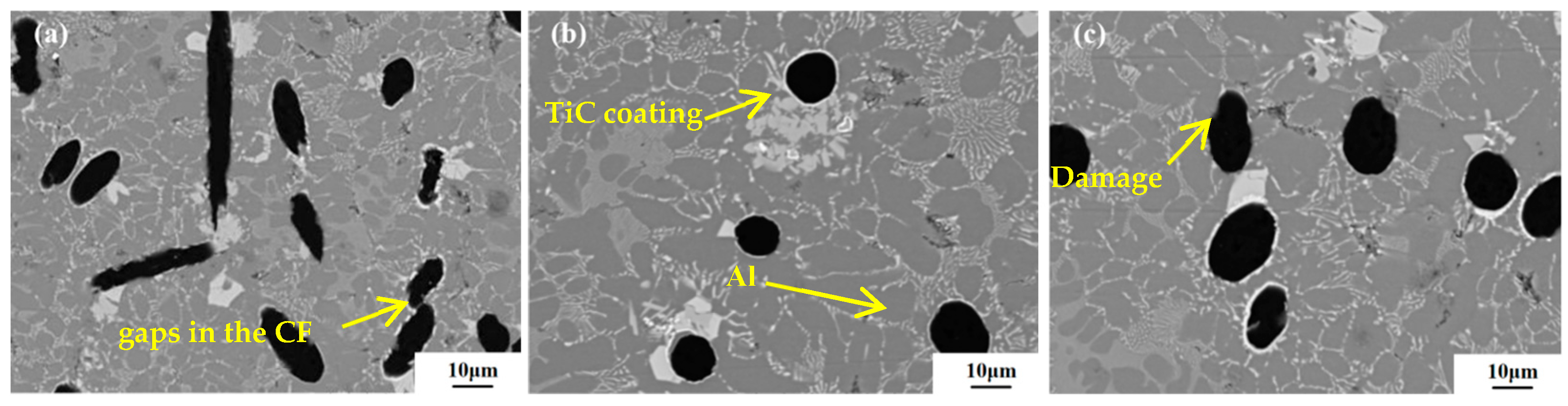
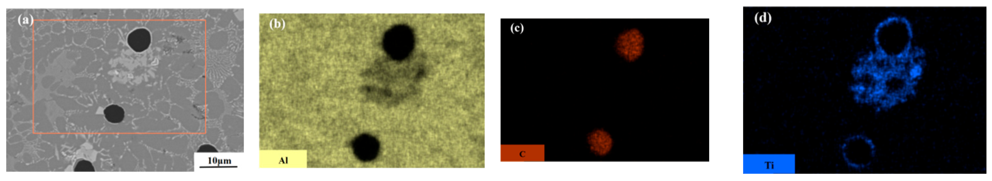
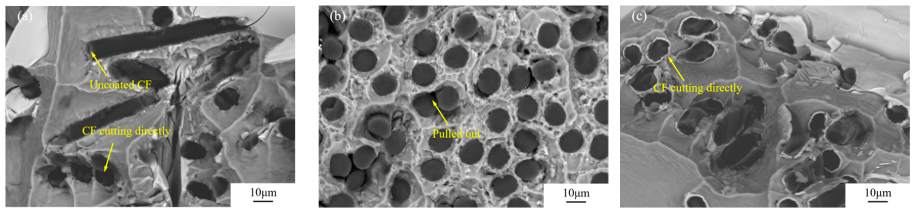
3.2. Microstructure and Analysis of TiC-CF/Al Composite Materials

When the holding time during the molten salt reaction is only 1 h, TiC fails to completely encapsulate the CF, which is not conducive to the performance strengthening of TiC-CF/Al composite materials. The microstructure of TiC-CF/Al composite materials prepared by the vacuum pressure infiltration method using TiC-CF prepared under holding times of 2 h, 3 h, and 4 h is shown in Figure 7. The vacuum pressure infiltration technology ensures the effective dispersion of TiC-CF in the matrix [32]. The holding time for the molten salt reaction was extended from 2 h to 4 h, and the CF in the composite matrix was evenly distributed. However, due to the dissolution of residual Ti particles on the coating surface in the Al matrix, the aggregation of white, block-shaped Ti particles in the TiC-CF/Al composite matrix increased, and a dark-white Al-Ti intermetallic phase was formed [33].
As shown in Figure 8a, when the holding time of the molten salt reaction is 2 h, there is no significant gap at the junction between the TiC-hhhCF and Al matrix, indicating that the wettability between the CF and Al matrix has been enhanced. However, local damage occurred to the TiC coating, resulting in an incomplete surface morphology of the CF and a blurred interface at the direct contact with the Al substrate. The interface reaction may have generated Al4C3 [34]. This indicates that although the coating obtained after 2 h of holding significantly improves the wettability of the CF, its strength is affected due to the thin coating, and coating damage limits the optimization of its overall performance. When the holding time of the molten salt reaction reaches 3 h, the CF distribution inside the composite material is uniform. And the CF maintains its original shape, at which point the interface reaction has significantly weakened. In the preparation process of CF/Al composite materials, due to the high melting point of the Ti element, its diffusion ability in the Al melt is limited during the rapid preparation process. As a result, the Ti element is often concentrated near the CF surface in the composite material, forming a rich Ti phase, as shown in Figure 9. The Ti element that segregates near the CF in the matrix will supplement the detached coating, thereby suppressing the formation of the Al4C3 compound [35]. This constitutes the second protective barrier against the CF. However, when the holding time of the molten salt reaction was increased to 4 h, significant differences in the thickness of TiC coatings on different fiber surfaces were observed, and an uneven coating was observed on the surface of the same CF, with local damage, resulting in gaps in the CF.

3.3. Mechanical Properties of TiC-CF/Al Composite Materials

Table 2 and Figure 10 show the stress–strain curves of the pure aluminum matrix and TiC-CF/Al composite material. After retaining three valid values for each group, we took the average and plotted the tensile strength curve. Pure Al exhibits a high toughness, low tensile strength, and good elongation. The measured tensile strength of pure Al is 60.30 MPa.
In TiC CF/Al composites prepared by the molten salt reaction, the retention time of the coating prepared by the molten salt reaction method is 2 h; the interfacial bonding strength was improved due to the introduction of TiC, resulting in a significant increase in tensile strength, reaching 88.21 MPa. Compared with the pure Al matrix, the strength was increased by about 46.28%. The holding time for the molten salt reaction is 3 h, and an appropriate increase in the coating thickness promotes the bonding between the coating, CF, and substrate. The tensile strength of this composite material reaches its highest value, with a tensile strength of 103.93 MPa, which is about 72.35% higher than that of the pure Al substrate. When the holding time for the molten salt reaction is 4 h, the excessive reaction of the CF leads to a decrease in its own stiffness, and the contribution of the damaged CF to the adhesive strength is relatively limited, resulting in weak bonding between the CF and TiC. The tensile strength of the composite material is 94.50 MPa, which is about 56.7% higher than that of the pure Al matrix.
Figure 11 shows the fracture morphology of Ti-CF/Al specimens prepared using the CF with different coating thicknesses. As shown in Figure 11a, the CFs with coating damage were observed in the fracture surface of the TiC-CF/Al composite material prepared by coating with a holding time of 2 h. Due to the unevenness of the coating surface, the bonding strength between the CF and Al substrate is insufficient. Meanwhile, when the Al melt comes into direct contact with the CF, it is prone to the formation of brittle-phase Al4C3, which seriously damages the CF interface and becomes a crack source [36,37]. In the TiC-CF/Al composite material prepared by coating with a holding of 3 h, the bonding strength between the CF and Al matrix is high, and the overall composite exhibits a short pull-out fracture morphology. The formation of tearing ridges around the short pulled out fibers is consistent with the mechanisms of fiber debonding and fiber pull-out fracture [38]. The strength of the TiC-CF bonding interface exceeds the tensile strength that the TiC coating can withstand. In the process of resisting tensile deformation in composite materials, when the TiC-CF structure exhibits a core–shell structure, the crack source starts from the coating and leads to fracture, and the CF inside the shell will also fracture in weak areas. When TiC-CF achieves effective bonding, the shear effect at the coating interface can be effectively transmitted to the carbon fiber reinforcement [39,40]. In addition, CF reinforcements typically have a high stiffness, resulting in shear fracture when subjected to tensile failure [41,42].
The TiC-CF/Al composite material prepared by coating obtained after 4 h of holding treatment mainly exhibits shear fracture characteristics as a whole. As shown in Figure 11c, the prolonged molten salt reaction time of the CF leads to damage to its matrix, which in turn causes a decrease in the stiffness of the monofilament. In addition, the thickness of the TiC coating is relatively large, resulting in a relatively weak bonding force at the TiC-CF interface. Therefore, during the stretching process, the CF is more prone to shear fracture, leading to the overall shear fracture of the composite material [43], and it also triggers shear fracture between the CF and the coating.
The introduction of CF leads to brittle fracture characteristics in CF/Al composites, which is fundamentally due to the significant mismatch in mechanical properties between the high elastic modulus of the CF and the low elastic modulus of Al. This mismatch makes it difficult for CF/Al composite materials to absorb energy through plastic deformation under stress, resulting in a decrease in their toughness. And in TiC CF/Al, the interface combination may be relatively strong at the macro level, but at the micro level it may form stress concentration points, which can easily become the origin of cracks when the material is subjected to tensile stress, thereby limiting the material’s ductility. If sufficient interface bonding is formed between the CF and Al matrix, the interface can effectively disperse stress, thereby enabling the CF to resist tensile deformation under stress. During the molten salt reaction process, when the CF holding time is 3 h, the TiC-CF interface bonding strength is higher, and the fracture surface tends to be a short fiber pull-out fracture, significantly improving the tensile strength of TiC-CF/Al composite materials.

4. Conclusions

This article explores, in detail, the influence of adjusting the holding time during the molten salt reaction process on the interface thickness of TiC-CF and the microstructure and properties of TiC-CF/Al composites. The conclusions of this study are as follows:
(1)
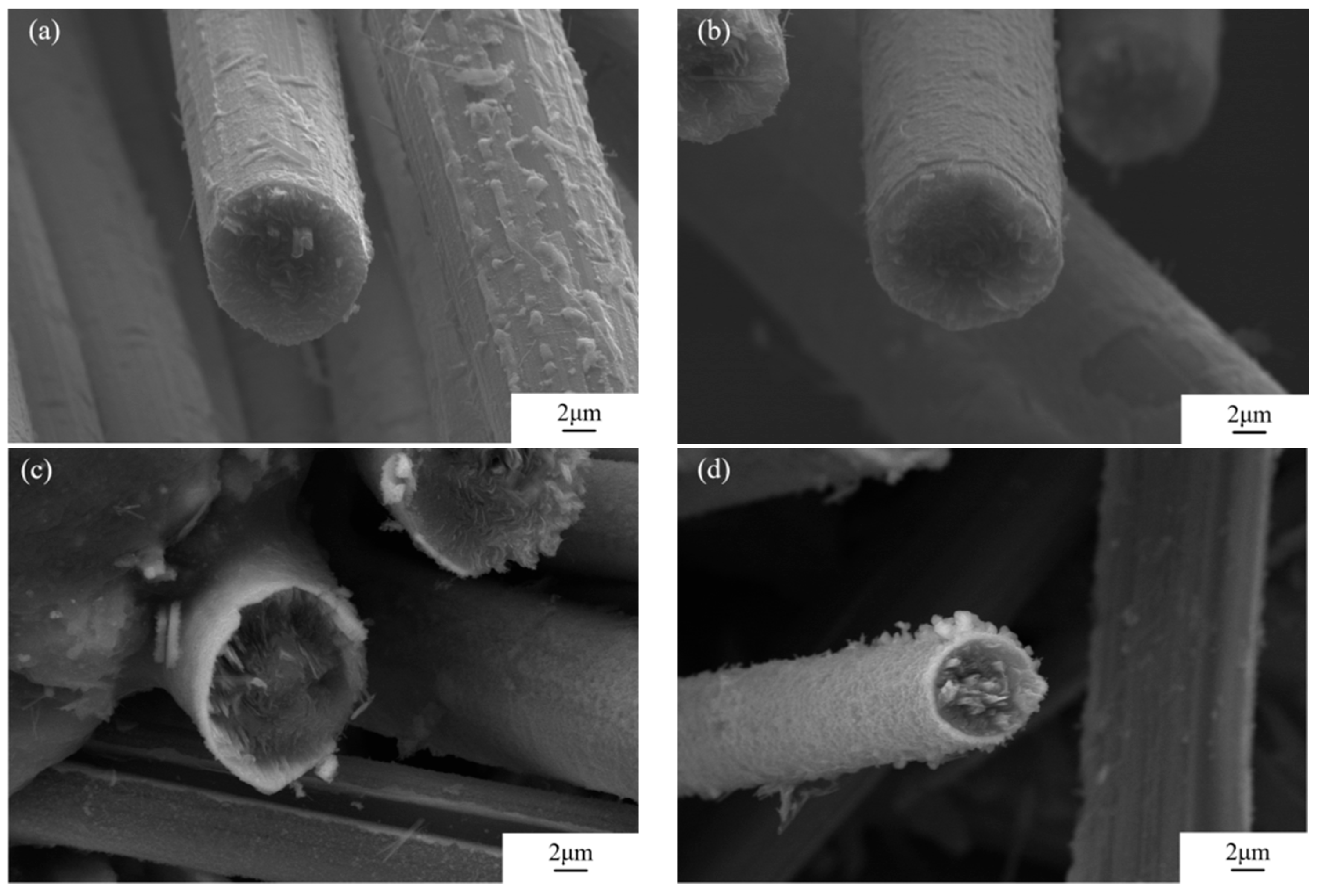
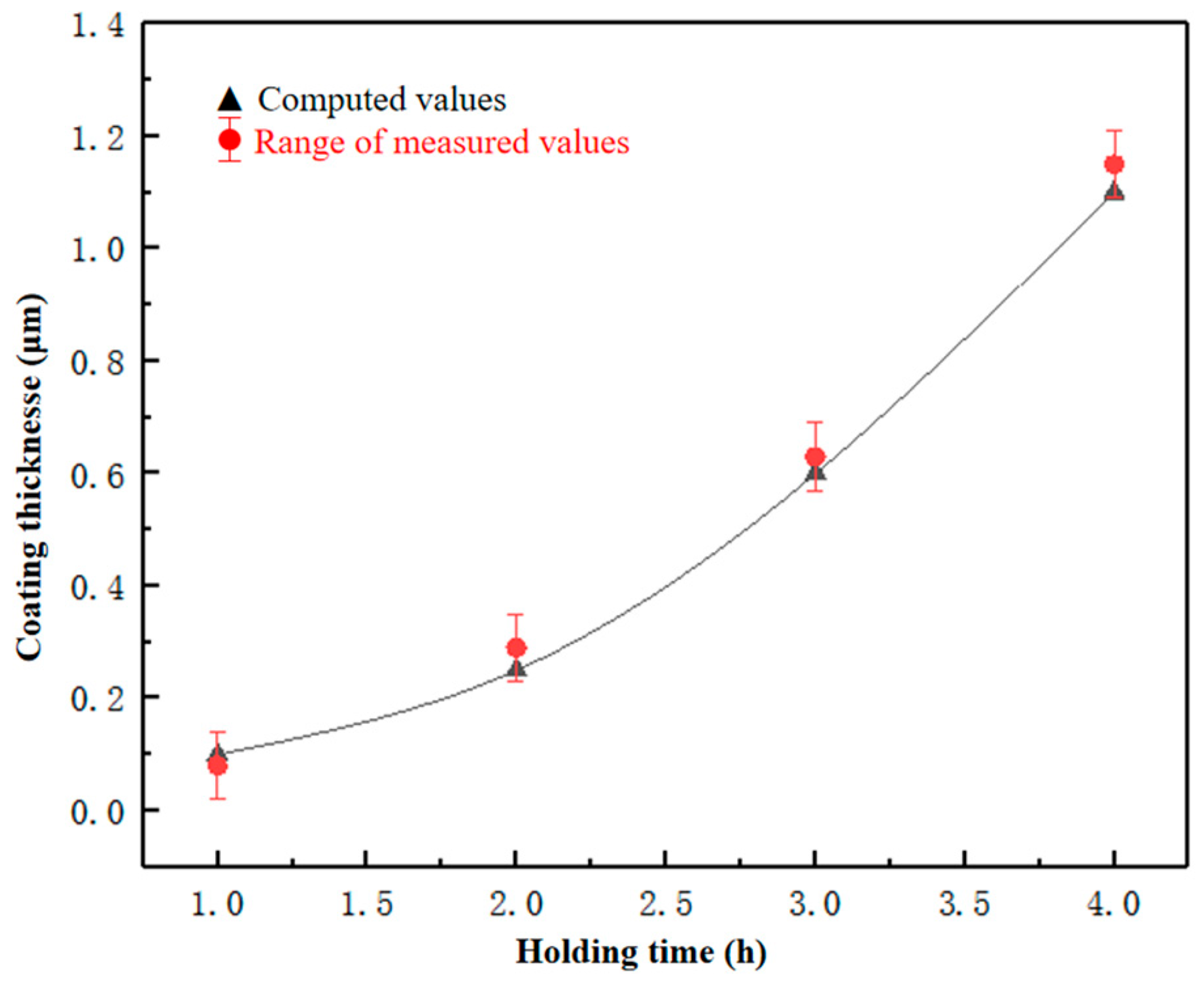
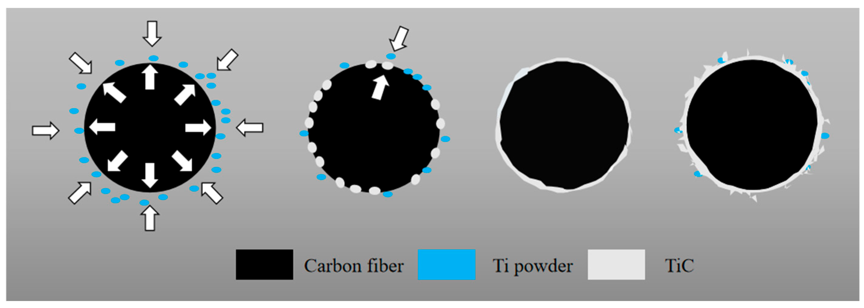
As the holding time of the molten salt reaction increases from 1 h to 4 h, the thickness of the TiC coating increases and the morphology gradually becomes rougher, and this trend is positively correlated with the increase in the holding time. The coating reaches a fully coated state on the surface after 2 h of holding.
(2)
The presence of the intact TiC coating on the surface of the CF can not only effectively improve the wettability between the CF and aluminum melt but also suppress the reaction between the CF and aluminum. However, an excessively thick coating not only reduces the strength of the fibers, due to excessive reactions, but also makes the coating prone to detachment during the preparation process due to stress.
(3)
When the holding time is 3 h, the strength of the TiC-CF bonding interface exceeds the tensile strength that the TiC coating can withstand, effectively transferring the load during deformation. The tensile strength reached 103.93 MPa, which is 72.35% higher than the tensile strength of the pure aluminum matrix.
This paper did not delve deeply into the bonding mechanism of the TiC-CF interface, and future research directions can start from the perspective of exploring chemical bonding and mechanical interlocking. It can also explore the changes in the interfacial bonding strength under different insulation times, as well as the impact of changes in the interfacial structure on the properties of composite materials.

Author Contributions

Conceptualization, H.Z. and Y.L.; methodology, H.Z.; software, H.Z. and W.L.; validation, H.Z., Y.L. and W.L.; formal analysis, H.Z. and X.M.; investigation, H.Z., Y.L. and X.M.; resources, H.Z. and Y.L.; data curation, H.Z., W.L. and G.L.; writing—original draft preparation, H.Z. and W.L.; writing—review and editing, H.Z., X.M. and W.L.; visualization, H.Z. and X.M.; supervision, H.Z. and G.L.; project administration, H.Z. and G.L.; funding acquisition, Y.L. and G.L. All authors have read and agreed to the published version of the manuscript.

Funding

This research was funded by National Natural Science Foundation of China (Grant No. 52174228).

Data Availability Statement

The original contributions presented in this study are included in the article. Further inquiries can be directed to the corresponding author.

Conflicts of Interest

Author Hongkui Zhang was employed by the CCTEG Shenyang Research Institute; and was employed by the Fushun CCTEG Inspection Center Co., Ltd. The remaining authors declare that the research was conducted in the absence of any commercial or financial relationships that could be construed as a potential conflict of interest.

References

  1. Pawlak, A.M.; Górny, T.; Dopierała, L.; Paczos, P. The Use of CFRP for Structural Reinforcement-Literature Review. Metals 2022, 12, 1470. [Google Scholar] [CrossRef]
  2. Chakrapani, P.; Suryakumari, T.S.A. Mechanical properties of aluminium metal matrix composites—A review. Mater. Today Proc. 2021, 9, 247. [Google Scholar] [CrossRef]
  3. Selvamuthukumar, M.; Bobba, S.; Padmanabhan, S.; Satyanarayana, D. Analysis of glass and carbon fiber-reinforced aluminum-sandwiched composites in automotive applications. J. Inst. Eng. (India) Ser. D 2024, 105, 725–731. [Google Scholar] [CrossRef]
  4. Mirza, H.A.; Lang, L.; Tabasum, M.N.; Meng, Z.; Alexandrov, S.; Jiang, J. An investigation into the forming of fiber metal laminates with different thickness metal skins using hydromechanical deep drawing. Appl. Compos. Mater. 2022, 29, 1349–1365. [Google Scholar] [CrossRef]
  5. Guo, K.W. Fracture Characteristics of Welded Joints in Aluminum Matrix Composites; Springer: Cham, Switzerland, 2025; pp. 22–62. [Google Scholar]
  6. Kuang, C.; Zhou, Y.; Zhu, H.; Shi, Q.; Fu, K.; Li, Y. Thermal and mechanical damage to carbon fibre reinforced composites with metallic fasteners under lightning strike. Thin-Walled Struct. 2023, 193, 111280. [Google Scholar] [CrossRef]
  7. Solazzi, L.; Danzi, N.; Pasinetti, M. Development and design of an innovative and lightweight reconnaissance rover using composite materials. J. Multiscale Model. 2024, 15, 24410003. [Google Scholar] [CrossRef]
  8. Yang, H.; Chang, M.; Wu, C. Continuous casting preparation process of helical fiber-reinforced metal matrix composites. Metals 2024, 14, 832. [Google Scholar] [CrossRef]
  9. Tanaka, K.; Aiba, Y. Evaluation of joint strength for CFRPs and aluminum alloys by friction stir spot welding using multi-stage heating. J. Compos. Sci. 2024, 8, 110. [Google Scholar] [CrossRef]
  10. Li, G.L.; Qu, Y.D.; Zhou, Q.W.; Man, C.; Zhou, S.; Li, R.D. Effect of fiber binding force on the molding of Cf/Al composites. Mater. Res. Express 2019, 6, 105619. [Google Scholar] [CrossRef]
  11. Nishi, Y.; Sagawa, K.; Faudree, M.C.; Uchida, H.T.; Kanda, M.; Kaneko, S.; Salvia, M.; Matsumura, Y.; Kimura, H. A novel nickel-plated Carbon Fiber insert in Aluminum joints with thermoplastic abs polymer or stainless steel. Materials 2023, 16, 5777. [Google Scholar] [CrossRef]
  12. Hu, S.F.; Sun, Z.Z.; Shen, F.H.; Deng, J.; Yang, W.P.; Yang, H.K. Carbon fiber breakage mechanism in aluminum(Al)/carbon fibers(CFS) composite sheet during accumulative roll bonding(ARB) process. J. Wuhan Univ. Technol. (Mater. Sci.) 2024, 39, 167–173. [Google Scholar] [CrossRef]
  13. Liu, T.T.; He, X.B.; Liu, Q.; Ren, S.B.; Kang, Q.P.; Zhang, L.; Qu, X.H. Effect of chromium carbide coating on thermal properties of short graphite fiber/Al composites. J. Mater. Sci. 2014, 49, 6705–6715. [Google Scholar] [CrossRef]
  14. Urea, A.; Rams, J.; Escalera, M.D. Effect of copper electroless coatings on the interaction between a molten Al-Si-Mg alloy and coated short carbon fibres. Compos. Part A Appl. Sci. Manuf. 2007, 38, 1947–1956. [Google Scholar] [CrossRef]
  15. Hajjari, E.; Divandari, M.; Mirhabibi, A.R. The effect of applied pressure on fracture surface and tensile properties of nickel coated continuous carbon fiber reinforced aluminum composites fabricated by squeeze casting. Mater. Des. 2010, 31, 2381–2386. [Google Scholar] [CrossRef]
  16. Gupta, N.; Nguyen, N.Q.; Rohatgi, P.K. Analysis of active cooling through nickel coated carbon fibers in the solidification processing of aluminum matrix composites. Compos. Part. B-Eng. 2011, 42, 916–925. [Google Scholar] [CrossRef]
  17. Rohatgi, P.K.; Tiwari, V.; Gupta, N. Squeeze infiltration processing of nickel coated carbon fiber reinforced Al-2014 composite. J. Mater. Sci. 2006, 41, 7232–7239. [Google Scholar] [CrossRef]
  18. Zhou, Q.W.; Li, G.L.; Zhou, Z.; Qu, Y.D.; Li, R.D. Effect of Ni2+ concentration on microstructure and bonding capacity of electroless copper plating on carbon fiber. J. Alloys Compd. 2021, 863, 158467. [Google Scholar] [CrossRef]
  19. Yang, D.C.; Zhao, X.; Ren, X.W.; Yan, S.L.; Gao, Y.H.; Liu, H.B. Effect of Stress Aging on Strength, Toughness and Corrosion Resistance of Al-10Zn-3Mg-3Cu Alloy. Materials 2025, 18, 181. [Google Scholar] [CrossRef]
  20. Alten, A.; Erzi, E.; Gürsoy, O.; Agaoglu, G.H.; Dispinar, D.; Orhan, G. Production and mechanical characterization of Ni-coated carbon fibers reinforced Al-6063 alloy matrix composites. J. Alloys Compd. 2019, 787, 543–550. [Google Scholar] [CrossRef]
  21. Tang, Y.P.; Liu, L.; Li, W.W.; Shen, B.; Hu, W.B. Interface characteristics and mechanical properties of short carbon fibers/Al composites with different coatings. Appl. Surf. Sci. 2009, 255, 4393–4400. [Google Scholar] [CrossRef]
  22. Si, H.L.; Zhou, Q.W.; Zhou, S.; Zhang, J.; Liu, W.J.; Gao, G.H.; Wang, Z.M.; Hou, P.Q.; Qu, Y.D.; Li, G.L. Effect of interfacial stabilityon microstructure and properties of carbon fiber reinforced aluminum matrix composites. Surf. Interfaces 2023, 38, 102816. [Google Scholar] [CrossRef]
  23. Xiong, Y.; Wang, W.L.; Ye, Z.; Yang, J.; Zhao, Y.; Huang, J.H. Fabrication and mechanical properties of TiC coated short carbon fiber reinforced Ti5Si3-TiC composites. Mater. Sci. Eng. A 2024, 893, 146135. [Google Scholar] [CrossRef]
  24. Dong, Z.J.; Li, X.K.; Yuan, G.M.; Cui, Z.W.; Cong, Y.; Westwood, A. Tensile strength, oxidation resistance and wettability of carbon fibers coated with a TiC layer using a molten salt method. Mater. Des. 2013, 50, 156–164. [Google Scholar] [CrossRef]
  25. Park, S.; Cho, M. Effect of anti-oxidative filler on the interfacial mechanical properties of carbon-carbon composites measured at high temperature. Carbon Int. J. Spons. Am. Carbon Soc. 2000, 38, 1053–1058. [Google Scholar] [CrossRef]
  26. Behboudi, F.; Kakroudi, M.G.; Vafa, N.P.; Faraji, M.; Milani, S.S. Molten salt synthesis of in-situ TiC coating on graphite flakes. Ceram. Int. 2020, 47, 8161–8168. [Google Scholar] [CrossRef]
  27. Kjamarani, K.M.; Clark, I.M. Characterization of particle size based on fine and coarse fractions. Powder Technol. 1997, 93, 101–108. [Google Scholar] [CrossRef]
  28. Li, X.; Dong, Z.; Westwood, A.; Brown, A.; Zhang, S.; Brydson, R.; Nan, L.; Rand, B. Preparation of a titanium carbide coating on carbon fibre using a molten salt method. Carbon 2008, 46, 305–309. [Google Scholar] [CrossRef]
  29. Nagarjuna, C.; Dewangan, S.K.; Lee, K.; Ahn, B. Mechanical and thermal expansion behaviour of TiC-reinforced CoCrFeMnNi high entropy alloy prepared by mechanical alloying and spark plasma sintering. Powder Metall. 2023, 25, 613–622. [Google Scholar] [CrossRef]
  30. Nguyen, N.Q.; Peterson, S.D.; Gupta, N.; Rohatgi, P.K. Modeling the effect of active fiber cooling on the microstructure of fiber reinforced metal matrix composites. Metall. Mater. Trans. A 2009, 40, 1911–1922. [Google Scholar] [CrossRef]
  31. Wang, Y.; Wang, C.; You, Y.; Cheng, W.; Dong, M.; Zhu, Z.; Liu, J.; Xie, W.; Wang, L.; Zhang, X.; et al. Finite element simulations of thermal stress distribution in thermal barrier coatings with different mullite whisker arrangements. Ceram. Int. 2024, 50, 43397–43413. [Google Scholar] [CrossRef]
  32. Swaffield, D.; Lewis, C.; Eugene, J.; Ingles, J.; Peach, D. Testing of machine wound second generation HTS tape Vacuum Pressure Impregnated coils. J. Phys. Conf. Ser. 2014, 507, 032046. [Google Scholar] [CrossRef]
  33. Zheng, M.; Zheng, T.; Chen, W.; Qu, D.; Chen, W.; Zhu, Z. Effect of interfacial microstructure on TiAl-Ti3Al biphase alloy was studied via molecular dynamics. Appl. Phys. A 2024, 131, 46. [Google Scholar] [CrossRef]
  34. Li, G.L.; Zhang, J.; Wang, Z.M.; Zhou, S.; Liu, W.J.; Zhang, W.; Zhang, H.K.; Qu, Y.D. Effect of Ni coating thickness on microstructure and properties of CF/Al composites prepared by vacuum pressure infiltration process. Mater. Sci. Eng. 2024, 222, 113101. [Google Scholar] [CrossRef]
  35. Sobczak, N.; Sobczak, J.; Seal, S.; Morgiel, J. TEM examination of the effect of titanium on the Al/C interface structure. Mater. Chem. Phys. 2003, 81, 319–322. [Google Scholar] [CrossRef]
  36. Nygren, G.; Wang, L.; Yang, Q.D.; Karkkainen, R. Microstructural effects on failure modes in highly aligned short carbon fiber composites. Polym. Compos. 2020, 41, 4288–4296. [Google Scholar] [CrossRef]
  37. Yang, Z.; Wu, T.; Liu, J.; Zhou, L.; Li, S. Interface optimization and mechanical properties of Cu-coated carbon fiber cloth/Titanium alloy composite. Rare Met. Mater. Eng. 2017, 46, 869–875. [Google Scholar]
  38. Lv, Z.Z.; Wang, J.; Guo, Y.J.; Dong, S.Q.; Sha, J.J.; Cheng, X.P. Effect of Cu coating thickness on carbon fiber surface on microstructure and mechanical properties of carbon fiber reinforced aluminum matrix composites. Mater. Today Commun. 2023, 34, 105424. [Google Scholar] [CrossRef]
  39. Wu, J.H.; Zhang, C.; Meng, Q.N.; Liu, B.C.; Sun, Y.H.; Wen, M.; Ma, S.M.; He, L.K. Study on tensile properties of carbon fiber reinforced AA7075 composite at high temperatures. Mater. Sci. Eng. A 2021, 825, 141931. [Google Scholar] [CrossRef]
  40. Chen, B.; Li, S.F.; Imai, H.; Jia, L.; Umeda, J.; Takahashi, M.; Kondoh, K. An approach for homogeneous carbon nanotube dispersion in Al matrix composites. Mater. Des. 2015, 72, 1–8. [Google Scholar] [CrossRef]
  41. Zhang, Y.L.; Hu, Z.; Yang, B.; Ren, J.; Li, H. Effect of pre-oxidation on the ablation resistance of ZrB2-SiC coating for SiC-coated carbon/carbon composites. Ceram. Int. 2015, 41, 2582–2589. [Google Scholar] [CrossRef]
  42. Li, F.; Liu, Y.; Qu, C.B.; Xiao, H.M.; Hua, Y.; Sui, G.X.; Fu, S.Y. Enhanced mechanical properties of short carbon fiber reinforced polyethersulfone composites by graphene oxide coating. Polymer 2015, 59, 155–165. [Google Scholar] [CrossRef]
  43. Zhu, J.W.; Jiang, W.M.; Li, G.Y.; Guan, F.; Yu, Y.; Fan, Z.T. Microstructure and mechanical properties of SiCnp/Al6082 aluminum matrix composites prepared by squeeze casting combined with stir casting. J. Mater. Process. Technol. 2020, 283, 1451. [Google Scholar] [CrossRef]
Figure 1. Process diagram for manufacturing TiC-CF/Al composite materials.
Metals 15 00459 g001
Figure 2. Shape and size of tensile specimen (Unit: mm).
Metals 15 00459 g002
Figure 3. Coating CF cross-section under different holding times: (a) 1 h; (b) 2 h; (c) 3 h; and (d) 4 h.
Metals 15 00459 g003
Figure 4. Coating thickness under different holding times.
Metals 15 00459 g004
Figure 5. Distribution of elements and surface composition analysis of TiC-CF cross-section: (ae) holding for 2 h; (fj) holding for 3 h; (k) surface composition analysis after 2 h of holding; and (l) surface composition analysis after 3 h of holding. The yellow box indicates the scanning range of EDS.
Metals 15 00459 g005
Figure 6. Growth mechanism of TiC on CF surface.
Metals 15 00459 g006
Figure 7. Morphology of TiC-CF/Al composite materials prepared using coatings of different thicknesses: (a) holding for 2 h; (b) holding for 3 h; and (c) holding for 4 h.
Metals 15 00459 g007
Figure 8. Morphology of TiC CF/Al composites prepared using coatings of different thicknesses at high magnification: (a) holding for 2 h; (b) holding for 3 h; and (c) holding for 4 h.
Metals 15 00459 g008
Figure 9. Energy spectrum analysis of TiC-CF/Al composite material with holding time of 3 h. (a) SEM (b) Al (c) C (d) Ti. The orange box indicates the scanning range of EDS.
Metals 15 00459 g009
Figure 10. Tensile curves of TiC-CF/Al composites prepared with coatings of different thicknesses.
Metals 15 00459 g010
Figure 11. Fracture morphology of TiC-CF/Al composite materials prepared with coatings of different thicknesses: (a) holding for 2 h; (b) holding for 3 h; and (c) holding for 4 h.
Metals 15 00459 g011
Table 1. Chemical composition of pretreatment solution.
ProcessSolution Composition
Degum20 g/L NaOH + 25 g/L Na2CO3 + 20 g/L Na3PO4 +
5 mL/L monoglyceride
Roughening treatment20 g/L K2CrO7 + 10 mL/L H2SO4
Table 2. Tensile strength of TiC-CF/Al composite materials.
Tensile Strength of TiC-CF/Al Composite Materials (MPa)
ExperimentExperiment 1Experiment 2Experiment 3Average
Holding time 2 h60.3262.6757.9160.30
Holding time 3 h89.3288.1387.1888.21
Holding time 4 h101.86104.351105.58103.93
Pure Al94.6096.3292.5894.50
Disclaimer/Publisher’s Note: The statements, opinions and data contained in all publications are solely those of the individual author(s) and contributor(s) and not of MDPI and/or the editor(s). MDPI and/or the editor(s) disclaim responsibility for any injury to people or property resulting from any ideas, methods, instructions or products referred to in the content.

