
Optimized and Additively Manufactured Face Mills for Enhanced Cutting Performance


Abstract

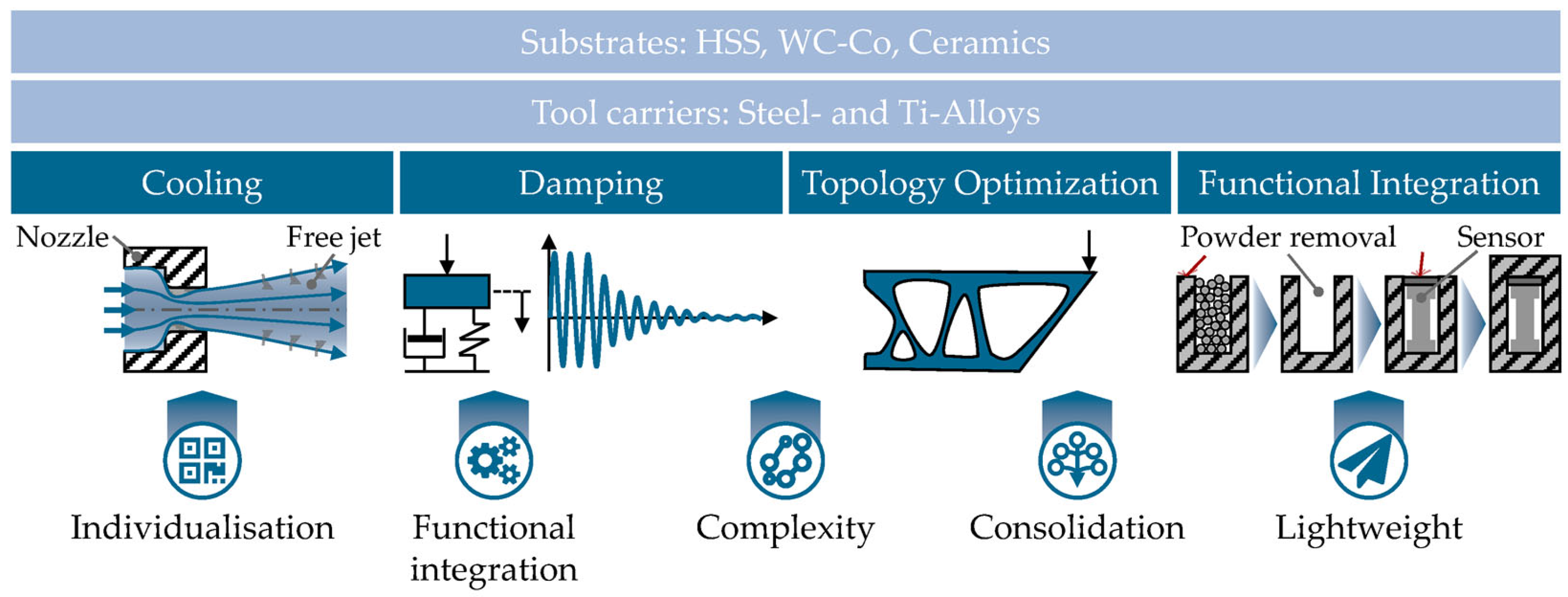
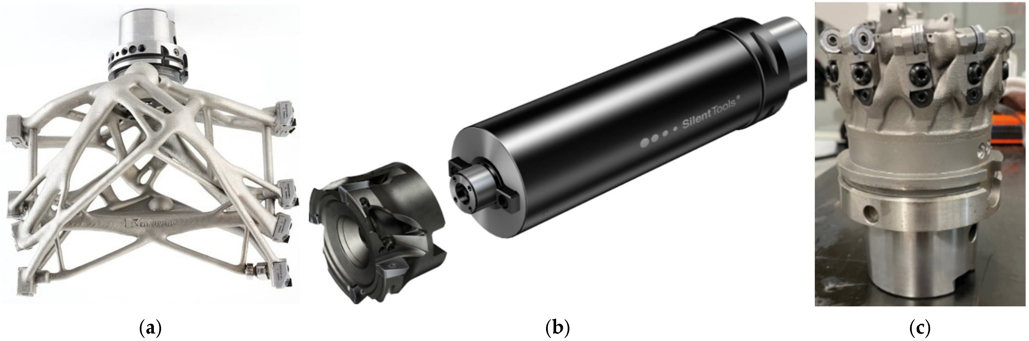
1. Introduction
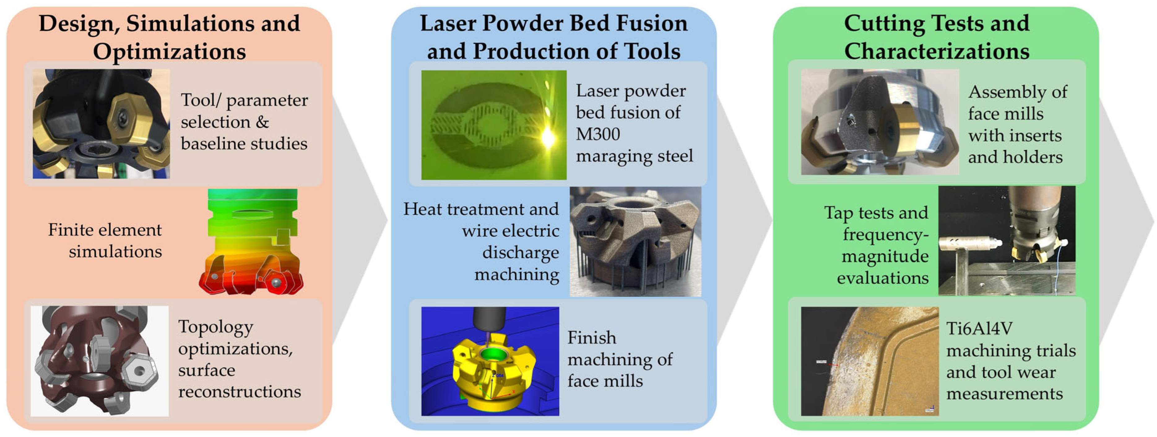
2. Materials and Methods
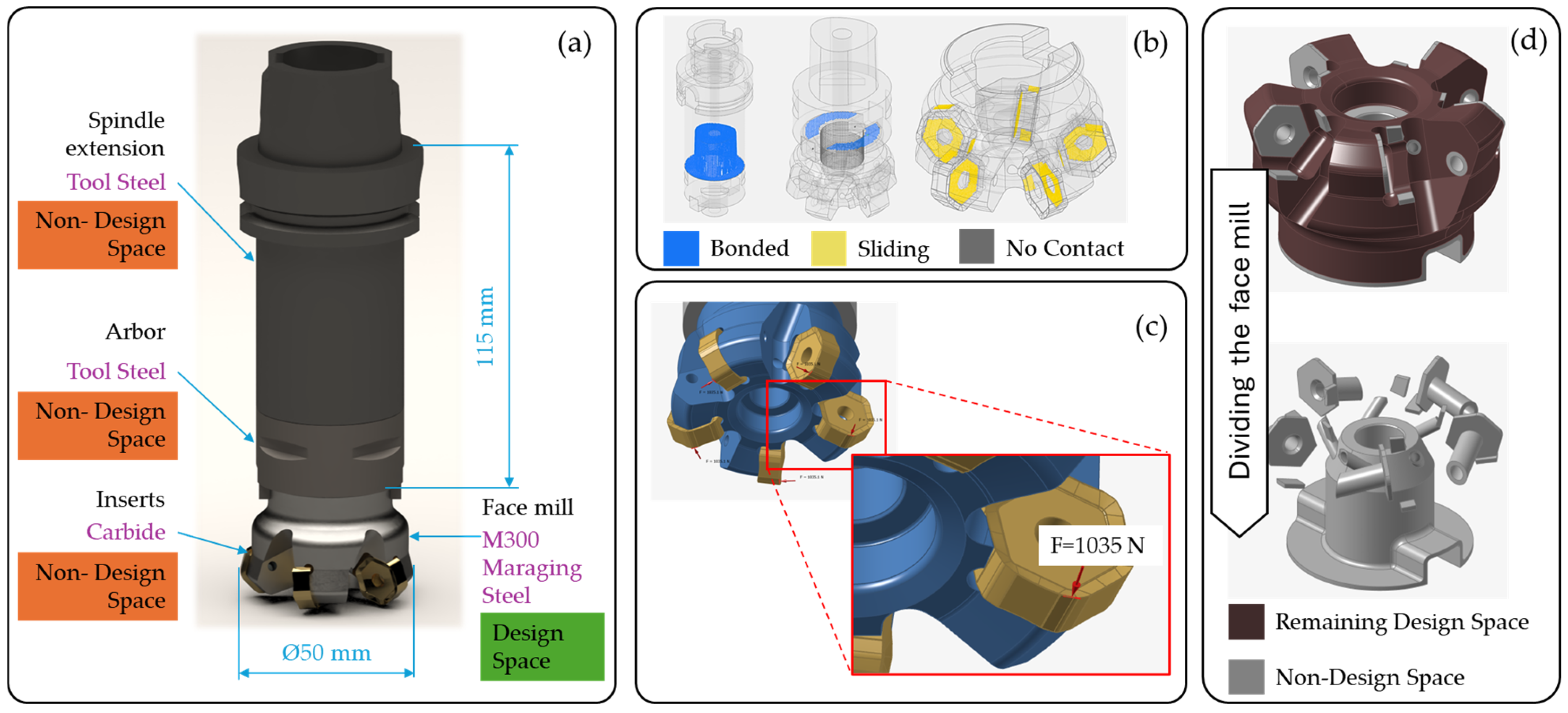
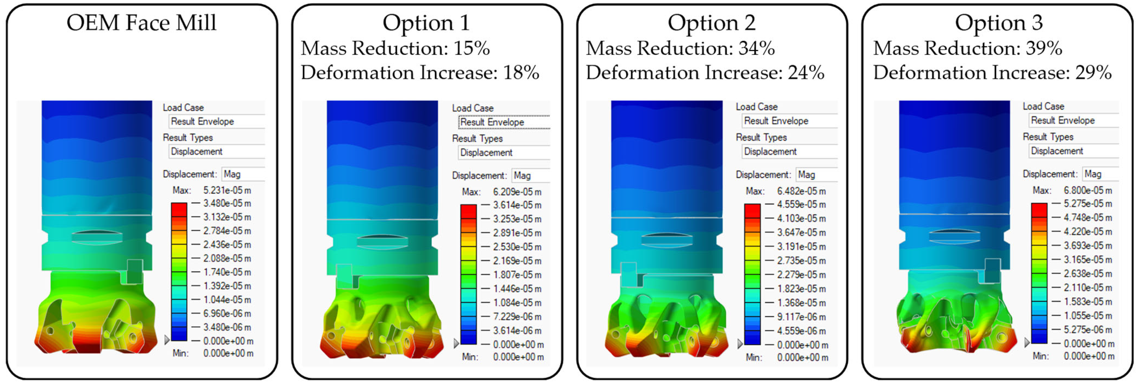
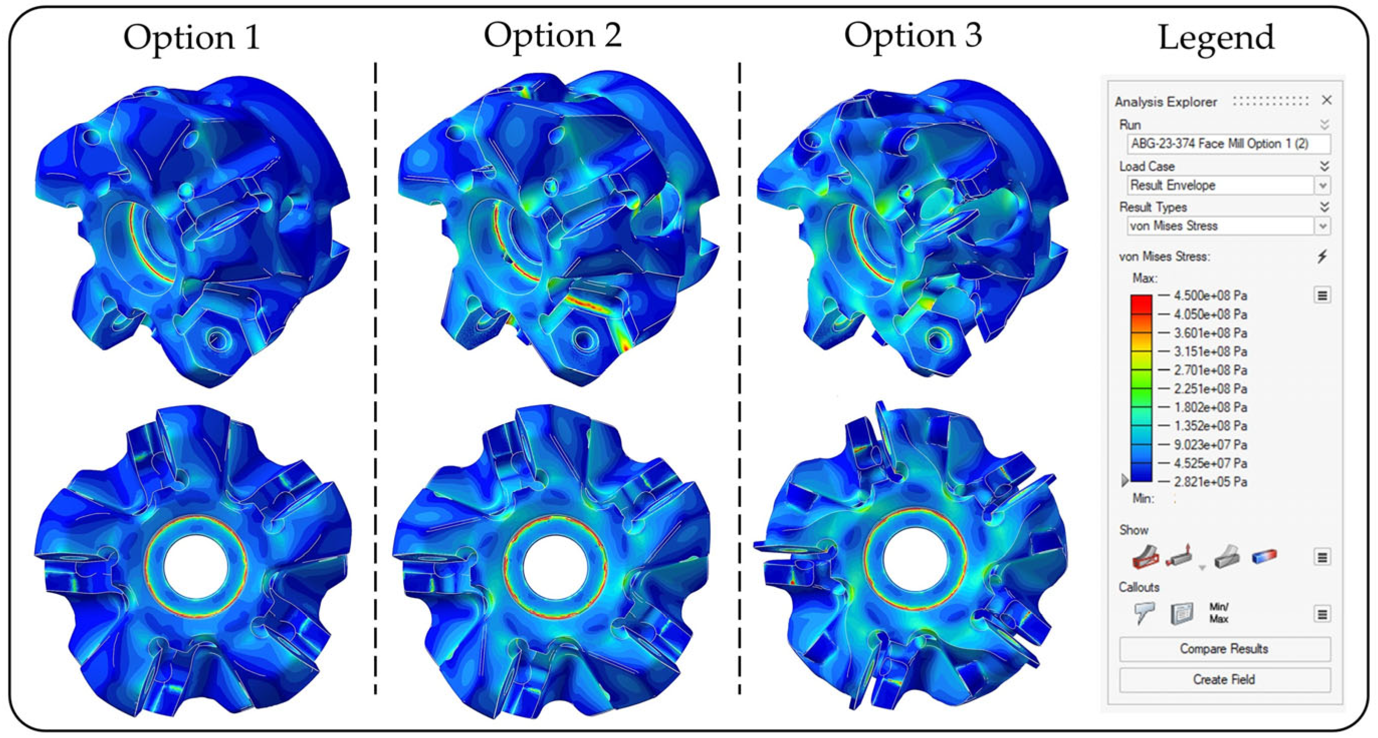
2.1. Design, Simulations and Optimizations
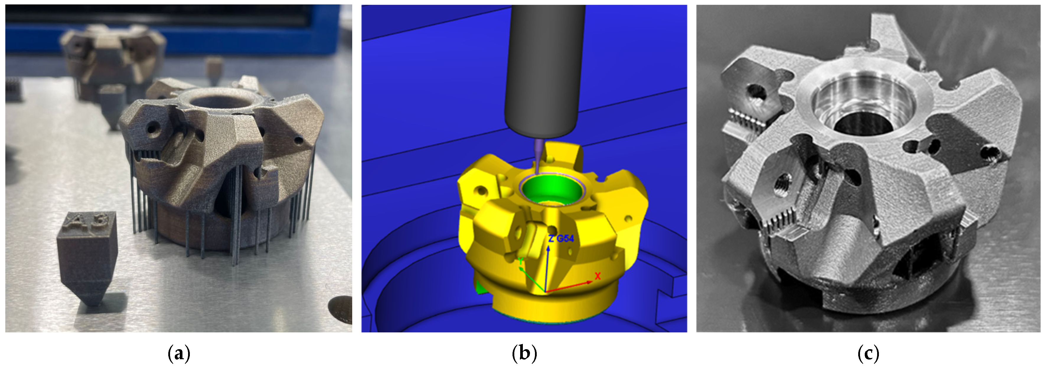
2.2. Laser Powder Bed Fusion and Production of Face Mills
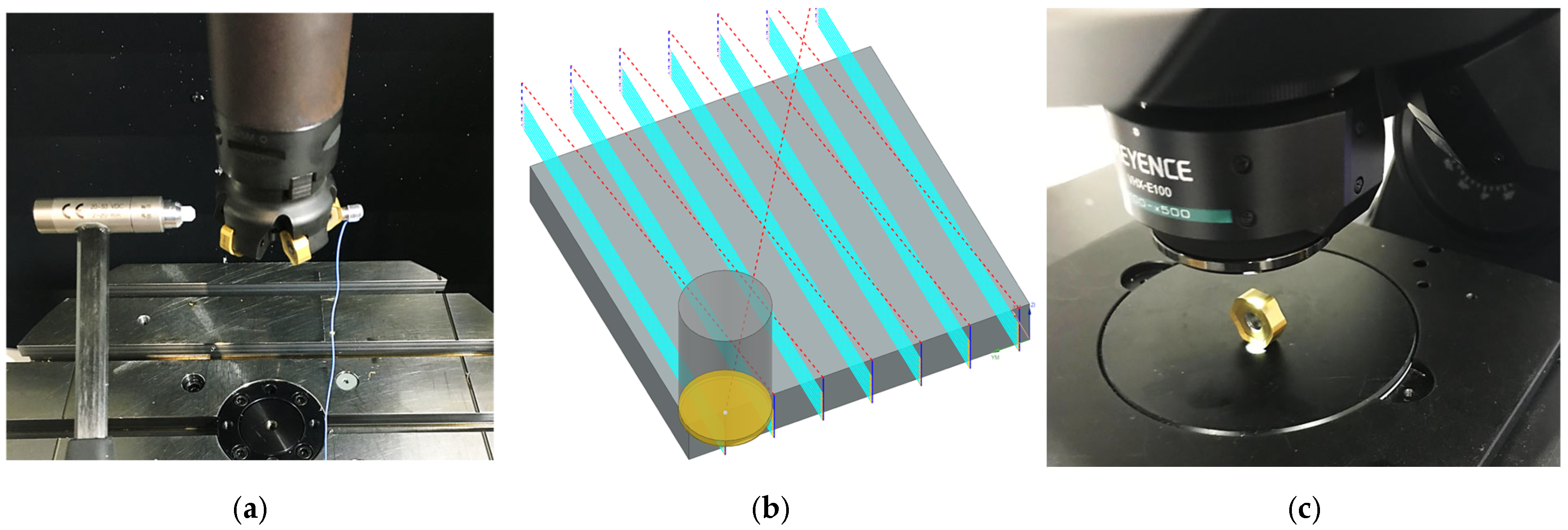
2.3. Tests and Investigations
3. Results and Discussions
4. Conclusions
Author Contributions
Funding
Data Availability Statement
Acknowledgments
Conflicts of Interest
Abbreviations
| 3D | Three-dimensional |
| AM | Additive manufacturing |
| BCC | Body centered cubic |
| BJ | Binder jetting |
| CAM | Computer aided manufacturing |
| DED | Directed energy deposition |
| DfAM | Design for additive manufacturing |
| Dv (X) | Particle size distribution for X percentage |
| FEA | Finite element analysis |
| ME | Material extrusion |
| MJ | Material jetting |
| OEM | Original equipment manufacture |
| PBF | Powder bed fusion |
| PBF-LB | Laser-based powder bed fusion |
| PCD | Ploy crystalline diamond |
| SR | Stress relieved |
| stl | Standard tessellation language file format |
| TO | Topology optimization |
| VB | Flank wear |
| Vc | Cutting speed |
| WEDM | Wire electric discharge machining |
References
- Martínez-García, A.; Monzón, M.; Paz, R. Standards for Additive Manufacturing Technologies. In Additive Manufacturing; Elsevier: Amsterdam, The Netherlands, 2021; pp. 395–408. ISBN 9780128184110. [Google Scholar]
- Leary, M.; Downing, D.; Lozanovski, B.; Harris, J. Design Principles. In Fundamentals of Laser Powder Bed Fusion of Metals; Elsevier: Amsterdam, The Netherlands, 2021; pp. 119–154. ISBN 9780128240908. [Google Scholar]
- Guan, J.; Wang, Q. Laser Powder Bed Fusion of Dissimilar Metal Materials: A Review. Materials 2023, 16, 2757. [Google Scholar] [CrossRef] [PubMed]
- Lupo, M.; Ajabshir, S.Z.; Sofia, D.; Barletta, D.; Poletto, M. Experimental Metrics of the Powder Layer Quality in the Selective Laser Sintering Process. Powder Technol. 2023, 419, 118346. [Google Scholar] [CrossRef]
- Depboylu, F.N.; Yasa, E.; Poyraz, O.; Korkusuz, F. Thin-Walled Commercially Pure Titanium Structures: Laser Powder Bed Fusion Process Parameter Optimization. Machines 2023, 11, 272. [Google Scholar] [CrossRef]
- Kundakcıoğlu, E.; Lazoglu, I.; Poyraz, Ö.; Yasa, E. Modeling of Residual Stress and Distortion in Direct Metal Laser Sintering Process: A Fast Prediction Approach. Prod. Eng. Res. Dev. 2022, 16, 769–783. [Google Scholar] [CrossRef]
- Flores, I.; Kretzschmar, N.; Azman, A.H.; Chekurov, S.; Pedersen, D.B.; Chaudhuri, A. Implications of Lattice Structures on Economics and Productivity of Metal Powder Bed Fusion. Addit. Manuf. 2020, 31, 100947. [Google Scholar] [CrossRef]
- Eren, O.; Kürşad Sezer, H.; Ersel Canyurt, O. Perspective Chapter: Design Considerations for Additive Manufacturing. In Product Design—A Manufacturing Perspective; Yasa, E., Poyraz, O., Eds.; IntechOpen: London, UK, 2024; ISBN 9781803565545. [Google Scholar]
- Khorasani, M.; Ghasemi, A.; Rolfe, B.; Gibson, I. Additive Manufacturing a Powerful Tool for the Aerospace Industry. Rapid Prototyp. J. 2022, 28, 87–100. [Google Scholar] [CrossRef]
- Hurtado-Pérez, A.B.; Pablo-Sotelo, A.D.J.; Ramírez-López, F.; Hernández-Gómez, J.J.; Mata-Rivera, M.F. On Topology Optimisation Methods and Additive Manufacture for Satellite Structures: A Review. Aerospace 2023, 10, 1025. [Google Scholar] [CrossRef]
- Goldstine, H.H. A History of the Calculus of Variations from the 17th Through the 19th Century; Studies in the History of Mathematics and Physical Sciences; Springer: New York, NY, USA, 1980; Volume 5, ISBN 9781461381082. [Google Scholar]
- Maxwell, J.C.I. On Reciprocal Figures, Frames, and Diagrams of Forces. Trans. R. Soc. Edinb. 1870, 26, 1–40. [Google Scholar] [CrossRef]
- Bendsøe, M.P.; Kikuchi, N. Generating Optimal Topologies in Structural Design Using a Homogenization Method. Comput. Methods Appl. Mech. Eng. 1988, 71, 197–224. [Google Scholar] [CrossRef]
- Altair. Topology Optimization and the Lessons of History. 2020. Available online: https://altair.com/blog/executive-insights/Topology-Optimization-and-the-Lessons-of-History#:~:text=As%20the%20world%20leader%20in,also%20saw%20the%20competitive%20advantages (accessed on 21 January 2025).
- Liu, S.; Li, Q.; Hu, J.; Chen, W.; Zhang, Y.; Luo, Y.; Wang, Q. A Survey of Topology Optimization Methods Considering Manufacturable Structural Feature Constraints for Additive Manufacturing Structures. Addit. Manuf. Front. 2024, 3, 200143. [Google Scholar] [CrossRef]
- Ibhadode, O.; Zhang, Z.; Sixt, J.; Nsiempba, K.M.; Orakwe, J.; Martinez-Marchese, A.; Ero, O.; Shahabad, S.I.; Bonakdar, A.; Toyserkani, E. Topology Optimization for Metal Additive Manufacturing: Current Trends, Challenges, and Future Outlook. Virtual Phys. Prototyp. 2023, 18, e2181192. [Google Scholar] [CrossRef]
- Kelliger, T.; Meurer, M.; Bergs, T. Potentials of Additive Manufacturing for Cutting Tools: A Review of Scientific and Industrial Applications. Metals 2024, 14, 982. [Google Scholar] [CrossRef]
- Lakner, T.; Bergs, T.; Döbbeler, B. Additively Manufactured Milling Tool with Focused Cutting Fluid Supply. Procedia CIRP 2019, 81, 464–469. [Google Scholar] [CrossRef]
- Kugaevskii, S.; Pizhenkov, E.; Gamberg, A. The Effectiveness of Additive SLM-Technologies in the Manufacture of Cutting Tools. Mater. Today Proc. 2019, 19, 1977–1981. [Google Scholar] [CrossRef]
- Zäh, M.; Seidel, C.; Sellmer, D. Technologie Report 08—Additive Fertigung; MAPAL Präzisionswerkzeuge Dr. Kress KG: Aalen, Germany, 2018. [Google Scholar]
- Vogel, F.A.M.; Berger, S.; Özkaya, E.; Biermann, D. Vibration Suppression in Turning TiAl6V4 Using Additively Manufactured Tool Holders with Specially Structured, Particle Filled Hollow Elements. Procedia Manuf. 2019, 40, 32–37. [Google Scholar] [CrossRef]
- Vogel, F.; Baumann, J.; Jaquet, S.; Biermann, D. Particle Damped Tool Holders Enable Higher Stability Limits When Milling EN AW-7075. SSRN J. 2023, 77–84. [Google Scholar] [CrossRef]
- Hanzl, P.; Zetek, M.; Rulc, V.; Purš, H.; Zetková, I. Finite Element Analysis of a Lightweight Milling Cutter for Metal Additive Manufacturing. Manuf. Technol. 2019, 19, 753–758. [Google Scholar] [CrossRef]
- Hanzl, P.; Zetková, I.; Zetek, M. Comparison of Lightweight and Solid Milling Cutter Capabilities. Manuf. Technol. 2020, 20, 23–26. [Google Scholar] [CrossRef]
- Tomasoni, D.; Giorleo, L.; Ceretti, E. Milling Tool Optimization by Topology Optimization Technique. ESAFORM 2021, 2021, 1–10. [Google Scholar] [CrossRef]
- Kennametal. Kennametal Innovation Earns International Recognition as Recipient of R&D 100 Award. 2023. Available online: https://www.kennametal.com/de/en/news/123114.html (accessed on 23 January 2025).
- Sandvik. How 3D-Printing and Titanium Became Game-Changers for Lightweight CoroMill® 390. 2020. Available online: https://www.metalpowder.sandvik/en/news-media/news/2020/07/additive-manufacturing-and-titanium-optimized-the-lightweight-coromill-390/ (accessed on 12 February 2025).
- Seco. Seco Tools 3D Manufacturing Creates New Opportunities. 2023. Available online: https://www.secotools.com/article/123840?language=en (accessed on 12 February 2025).
- Renishaw. M300 Maraging Steel Data Sheet. 2017. Available online: https://www.renishaw.com/resourcecentre/download/data-sheet-maraging-steel-m300-for-200-w-powder-for-additive-manufacturing--96325?userLanguage=en&srsltid=AfmBOoq3HAz4jS0jcXDJMppmcNjfWZyIduCVDA8sYjGEslKZRXPXXTtO (accessed on 23 January 2025).
- Davis, J.R.; ASM International (Eds.) Carbon and Alloy Steels; ASM Speciality Handbook; ASM International: Materials Park, OH, USA, 1996; ISBN 9780871705570. [Google Scholar]
- ASM International ASM Engineered Materials Reference Book; ASM International: Metals Park, OH, USA, 1989; ISBN 9780871703507.
- Carpenter. PowderRange M300 Data Sheet. Available online: https://www.carpenteradditive.com/hubfs/Resources/datasheets%202023/PowderRange_M300_Datasheet.pdf (accessed on 21 February 2025).
- ASTM B962-23; Standard Test Methods for Density of Compacted or Sintered Powder Metallurgy (PM) Products Using Archimedes’ Principle. American Society for Testing and Materials (ASTM): West Conshohocken, PA, USA, 2023.
- Metalweb. Titanium Ti-6Al-4V (Grade 5), STA. Available online: https://www.matweb.com/search/datasheet.aspx?MatGUID=b350a789eda946c6b86a3e4d3c577b39&ckck=1 (accessed on 25 February 2025).
- International Standard ISO 8688; Tool-Life Testing in Milling. ISO: Geneva, Switzerland, 1989.
- Liang, X.; Liu, Z.; Wang, B.; Hou, X. Modeling of Plastic Deformation Induced by Thermo-Mechanical Stresses Considering Tool Flank Wear in High-Speed Machining Ti-6Al-4V. Int. J. Mech. Sci. 2018, 140, 1–12. [Google Scholar] [CrossRef]
- Yue, C.; Li, X.; Liu, X.; Du, J.; Liang, S.Y.; Wang, L.; Sun, Y. Wear Behavior of Tool Flank in the Side Milling of Ti6Al4V: An Analytical Model and Experimental Validation. Proc. Inst. Mech. Eng. Part C J. Mech. Eng. Sci. 2022, 236, 1631–1644. [Google Scholar] [CrossRef]
- Dynamic Metals. AMS 6411 Alloy Steel Data. Available online: https://dynamicmetalsltd.com/products/alloy-steel/4330-alloy-steel/ (accessed on 13 March 2025).
- Dang, J.; Zang, H.; An, Q.; Ming, W.; Chen, M. Feasibility Study of Creep Feed Grinding of 300M Steel with Zirconium Corundum Wheel. Chin. J. Aeronaut. 2022, 35, 565–578. [Google Scholar] [CrossRef]


| Material | Density (kg/m3) | Elastic Modulus (GPa) | Yield Strength (MPa) | Reference No. |
|---|---|---|---|---|
| M300 | 8100 | 199 | 1873 | [29] |
| Tool Steel | 7800 | 210 | 1650 | [30] |
| Carbide | 15,700 | 669 | 300 | [31] |
| Original Face Mill | Unoptimized AM Face Mill | TO Option 1 Face Mill | TO Option 2 Face Mill | TO Option 3 Face Mill | |
|---|---|---|---|---|---|
| Mass (g) | 329 | 344 | 279 | 213 | 201 |
Disclaimer/Publisher’s Note: The statements, opinions and data contained in all publications are solely those of the individual author(s) and contributor(s) and not of MDPI and/or the editor(s). MDPI and/or the editor(s) disclaim responsibility for any injury to people or property resulting from any ideas, methods, instructions or products referred to in the content. |
© 2025 by the authors. Licensee MDPI, Basel, Switzerland. This article is an open access article distributed under the terms and conditions of the Creative Commons Attribution (CC BY) license (https://creativecommons.org/licenses/by/4.0/).
Share and Cite
Poyraz, O.; Tomlinson, D.; Molyneux, A.; Baxter, M.E.; Yasa, E.; Hughes, J. Optimized and Additively Manufactured Face Mills for Enhanced Cutting Performance. Metals 2025, 15, 376. https://doi.org/10.3390/met15040376
Poyraz O, Tomlinson D, Molyneux A, Baxter ME, Yasa E, Hughes J. Optimized and Additively Manufactured Face Mills for Enhanced Cutting Performance. Metals. 2025; 15(4):376. https://doi.org/10.3390/met15040376
Chicago/Turabian StylePoyraz, Ozgur, Daniel Tomlinson, Anthony Molyneux, Marie E. Baxter, Evren Yasa, and James Hughes. 2025. "Optimized and Additively Manufactured Face Mills for Enhanced Cutting Performance" Metals 15, no. 4: 376. https://doi.org/10.3390/met15040376
APA StylePoyraz, O., Tomlinson, D., Molyneux, A., Baxter, M. E., Yasa, E., & Hughes, J. (2025). Optimized and Additively Manufactured Face Mills for Enhanced Cutting Performance. Metals, 15(4), 376. https://doi.org/10.3390/met15040376