Article

Characterizing the Behavior and Microstructure of Cu-La2O3 Composite Processed via Equal Channel Angular Pressing

Department of Metallurgical Technologies, Faculty of Materials Science and Technology, VŠB Technical University of Ostrava, 17. listopadu 2172-15, 708 00 Ostrava, Czech Republic
*
Author to whom correspondence should be addressed.
Metals 2025, 15(4), 368; https://doi.org/10.3390/met15040368
Submission received: 2 March 2025 / Revised: 24 March 2025 / Accepted: 26 March 2025 / Published: 27 March 2025
(This article belongs to the Special Issue Design and Development of Metal Matrix Composites)

Abstract

:
Cu-based alloys and composites are popular to prepare electroconductive parts. However, their processing can be challenging, especially in case of composites strengthened with oxides. To save the necessary time and costs, numerical simulations can be of help when determining the deformation behaviour of (newly introduced) materials. The study presents a combined method of strengthening of Cu by adding 5 wt.% of La2O3 particles and performing shear-based deformation by equal channel angular pressing (ECAP). The effects of the method on the microstructure, mechanical properties, and thermal stability of the composite are examined both numerically and experimentally. The results showed that the La2O3 addition caused the maximum imposed strain to be higher for the composite than for commercially pure Cu, which led to the development of subgrains and shear bands within the microstructure, and a consequent increase in microhardness. The numerical predictions revealed that the observed differences could be explained by the differences in the material plastic flow (comparing the composite to commercially pure Cu). The work hardening supported by the addition of La2O3 led to a significant increase in stress and punch load during processing, as well as contributed to a slight increase in deformation temperature in the main deformation zone of the ECAP die. Certain inhomogeneity of the parameters of interest across the processed workpiece was observed. Nevertheless, such inhomogeneity is typical for the ECAP process and steps prospectively leading to its elimination are proposed.

1. Introduction

Cu of a high purity (commercially pure, CP) is a highly versatile conductive material, but features relatively low strength [1]. Advantageous ways of increasing the mechanical properties of Cu include application of various heat, deformation, and thermomechanical treatments [2,3,4,5], as well as additions of strengthening/reinforcing elements to create alloys [6,7] and composites [8,9]. As for the first mentioned way, optimized treatments enhancing the mechanical properties of Cu can advantageously be carried out by methods of intensive and severe plastic deformation (IPD, e.g., [10,11,12], and SPD, e.g., [13,14,15,16]). Such methods impart strengthening by introducing nucleation of dislocations and formation of substructure, resulting in grain refinement and consequently to improvement of the mechanical properties [17,18]. As for the second mentioned way, besides the alloying element typically added to fabricate the commonly known Cu-based alloys (e.g., bronzes and brasses [19,20]), additions of specific elements can improve the properties of Cu. For example, small amounts of Ag, Cd, or Fe were reported to improve the durability of Cu at elevated temperatures [21,22]. Cu-based composites are very advantageous for achieving specific combinations of properties. Both laminated composites, consisting of (multiple) layers of Cu + other elements (e.g., Mg [23,24,25], Al [26,27,28], Nb [29,30,31], Ti [32,33,34], combinations of elements [35,36], various alloys [37], graphene [38], etc.), and powder-based Cu composites, usually containing strengthening particles (carbon [39,40,41,42], various oxides, such as Al2O3 [43,44,45], or Y2O3 [46,47,48,49]), are widely researched.
The presented study introduces a Cu-based composite consisting of Cu + 5 wt.% of La2O3 particles. Cu is mainly used for electroconductive components, operating typically in contact with other (such) parts. Therefore, such parts can be subject to not only electrical erosion, but also wear by abrasion and adhesion [50]. For this reason, it is of a high importance to increase the mechanical (as well as tribological) properties of Cu-based electroconductive materials. This can advantageously be done by adding stable and resistant reinforcing particles, such as the La2O3. The La2O3 oxide was, similar to the Y2O3 one, documented to enhance the mechanical properties, especially hardness and elastic modulus, without having significantly negative effects on the electric conductivity [51]. Moreover, adding La2O3 to Cu was shown to be highly supportive of grain refinement, which is advantageous from the viewpoint of introducing another strengthening, by the Hall–Petch effect [52]. Nevertheless, contrary to Y2O3, the effects of La2O3 additions on the overall behavior of Cu have not been sufficiently studied yet (either experimentally or via numerical simulations).
The processing method selected herein is equal channel angular pressing (ECAP), a widely used and researched SPD method suitable for processing of relatively large billets (see, e.g., [53,54]). The positive effects of ECAP on the microstructures and properties of CP Cu and selected Cu-based alloys were documented. For example, Heidari et al. [55] increased the lifetime of a tool electrode Cu by ECAP, and Volokitina et al. [56] subjected CP Cu to ECAP under cryogenic conditions and achieved double the effectivity of room temperature ECAP as regards the increase in the mechanical properties. Guo et al. [57] subjected a Cu1Cr0.2Si alloy to four pass ECAP (route Bc [58]) and achieved an increase in its tensile strength by 47% (up to 564 MPa), whereas Chu et al. [59] used combinations of ECAP, rolling, and heat treatments to impart nano-sized structural features within a CuCrZr alloy to increase its tensile strength up to 730 MPa, while maintaining the electric conductivity of 75.5% IACS (International Annealed Copper Standard). Several types of Cu-based composites were also subjected to ECAP and other ECAP-based methods; for example, Cu-Al laminates were prepared by ECAP [60], ECAP + drawing [61], or TCAP (twist channel angular pressing) [62].
Numerical simulations using the finite element method (FEM) advantageously provide deeper insights into the production processes, as they enable to predict processing parameters, such as distribution of temperature, strain, stress, forming forces and their developments, etc. [63,64]. They can be advantageously used to study the microstructures and behaviors of metallic materials during processing by SPD methods, such as the ECAP process applied herein. For example, Borodin et al. [65] used FEM to predict the development of microstructural features within CuCrZr alloys during ECAP and multidirectional forging, Bratov et al. [66] used modelling to predict dislocations and grain size development within Cu and Al subjected to ECAP, Aal [67] numerically studied the deformation behavior of pure Al when deformed by ECAP, and a combination of ECAP and direct extrusion, Hongyu et al. [68] predicted the quality of shape control of a square Al tube during ECAP, Vafaeenezhad et al. [69] assembled a numerical model to analyze the effect of severe plastic deformation on wear of Al-7075 alloy deformed by ECAP, and Ghosh et al. [70] used computer simulations to investigate the deformation behavior of EN AW 7075 alloy during ECAP processing through dies with different outer corner angles. Nevertheless, to successfully assemble a numerical simulation, numerous input data and boundary conditions have to be set. Therefore, when proposing a new material, or examining a material the properties of which are not widely known, its behavior needs to be thoroughly studied at first to gain input data for the numerical modelling.
The study presented herein features a combined method of strengthening of CP Cu by adding La2O3 oxide particles and performing SPD by ECAP. The results were acquired both experimentally and via numerical simulations; the simulations were also performed for CP Cu to provide in-depth insight into the effects of La2O3 addition on the behavior of the composite. As characterized in the following section, the study starts with the investigation of the mechanical properties of the as-cast Cu-La2O3 composite. The acquired data were then advantageously used to assemble the numerical simulation to predict the behavior of the composite during the ECAP processing. Along with examining the mechanical properties, the experimentally prepared composite billets were subjected to detailed investigations of microstructures and investigation of their thermal stability (as electroconductive parts can experience temperature fluctuations). Subsequently, the numerical simulations were focused on assessing the material plastic flow and stress–strain conditions during processing, as well as on the processing parameters, such as deformation temperature and punch load. Finally, the acquired results were put in correlation to characterize the enhancement resulting from the performed processing steps.

2. Materials and Methods

2.1. Experimental

The used materials were electro-conductive CP Cu (impurities of, in wt.%, 0.002 O, 0.002 Zn, and 0.015 P), and La2O3 particles. The initial Cu was a commonly available as-cast electro-conductive Cu rod (UCB Technometal, s.r.o., Loděnice u Berouna, Czech Republic), while the La2O3 powder of 99.99% purity was obtained from Thermo Scientific Chemicals Inc. (Waltham, MA, USA). The initial composite material was cast by vacuum induction melting (VIM) to a 200 mm long billet with the diameter of 20 mm. Subsequently, the billet was machined to acquire 100 mm long workpieces with the cross-section of 10 × 10 mm2 for room temperature ECAP processing, which was performed via a single pass through a die with the bending angle of 110°. In order to confirm robustness of the experiment and repeatability of the results, all the experimental works, from casting to investigations, were doubled with another billet. As no significant discrepancies in the mechanical properties, microstructures, and overall behaviors of the billets were observed, the results from one billet are presented to keep the manuscript within a reasonable length.
Mechanical properties of the as-cast composite, as well as ECAP-processed composites, were at first examined using uniaxial compression testing (ASTM D7012-23 standard [71]) at room temperature (20 °C) and strain rate of 0.01 s−1. This particular strain rate was chosen based on the fact that the experimental ECAP processing was performed using a hydraulic press featuring very low strain rates, so the acquired data could subsequently be used to reliably perform the numerical simulations. However, higher strain rate values of 0.1 s−1 and 10 s−1 were also applied in order to experimentally characterize the deformation behavior of the prepared composite at a wider range of thermomechanical conditions, as well as to assess its thermal stability. The testing was carried out using a Gleeble 3800-GTC thermal-mechanical simulator equipped with a Hydrawedge II testing unit (both Dynamic System Inc., Poestenkill, NY, USA), see, e.g., [72,73,74]. The specimens were of a cylindrical shape with the dimensions of 10 mm in diameter and 15 mm in length. Each specimen was deformed by uniaxial compression to the final true strain of 1.0. To reduce friction on the contact surfaces between the anvils and the specimen and to protect the anvils, nickel-based lubricant with tantalum washers were used. The Gleeble 3800 equipment and testing samples of the above-described dimensions were also used for the experiments investigating the thermal stability of the ECAP-processed Cu-La2O3 composite. For this purpose, the heat treatment regime of 250° C/30 min was selected and applied on the ECAP-processed composite samples.
To experimentally acquire data on the mechanical properties for subsequent detailed comparison of the deformation behavior of the composite with the results of numerical simulations, Vickers microhardness HV0.05 was measured along two intersecting diagonals across the cross-sections of both the as-cast and ECAP-processed billets (see Figure 1). The load for the measurements was 50 g, and indent load time was 10 s (ASTM E384 standard [75], FM ARS 900 equipment by Future Tech, Spectrographic Limited, Leeds, UK).
Finally, samples for scanning electron microscopy (SEM) (electron backscatter diffraction, EBSD), were prepared from both, the as-cast and ECAP-processed billets (SEM by Tescan Orsay Holding a.s., Brno, Czech Republic). The billets were cut longitudinally along the axis to prepare samples, which were mechanically ground, and finally polished via an OPS (Oxide Polishing Suspension, by Struers s.r.o, Ostrava, Czech Republic). EBSD scans were acquired both from relatively larger areas to provide overviews of the microstructures, as well as from detailed views on the microstructures with 0.05 μm scan step to closely investigate the development of substructure. The results were evaluated with the limit values of 5° for low angle grain boundaries (LAGB), and 15° for high angle grain boundaries (HAGB).

2.2. Numerical Simulation

The numerical simulation of the ECAP process was assembled using the Forge software (version NxT®, Transvalor S.A., Biot, France), see, e.g., [76,77]. The comparative simulation of CP Cu was carried out using data files for 99.97% pure Cu already included in the material database of the software. The material behavior of the prepared composite was defined using the data acquired via the above-mentioned compression testing procedure. The data needed to be implemented into the software to assess the behavior of the composite. The material file of the prepared composite was filled in with the following parameters: Young’s modulus E of 110 MPa, Poisson’s ratio ν of 0.3, specific heat capacity c of 435 J·kg−1·K−1, and density ρ, of 8100 kg·m−3. The modification also consisted in adjusting the material constants of the Hensel–Spittel rheology law [78], see Equation (1),
σ = A e m 1 T ε m 2 ε ˙ m 3 e m 4 / ε 1 + ε m 5 T e m 7 ε ε ˙ m 8 T T m 9
where T (°C), ε (-), ε ˙ (s−1), and σ (MPa) represent the deformation temperature, true strain, strain rate, and true flow stress, respectively. The constants originally determined for the 99.97% pure Cu were recalculated for the examined Cu-La2O3 composite using regression analysis of the experimentally acquired data. The resulting constants, together with the original constants, are summarized in Table 1. When compared to the Hensel–Spittel model for the pure Cu, the model assembled for the Cu-La2O3 composite differed significantly in several key constants (see Table 1). These differences point to and explain the differences in the results predicted for the Cu and Cu-La2O3 composite, as further discussed in Section 3. Fundamental parameters affecting the material behavior are the coefficients influencing the strain hardening/softening processes, i.e., m2, m4, m5, and m7 (constants related to true strain). In the material database of the used Forge NxT® software, the constants m5 and m7 are equal to zero for pure Cu. However, for the Cu-La2O3 composite, these constants were considered to be non-zero in order to achieve the most reliable fit of the experimental data during the regression analysis.
The accuracy of the assembled model was verified by the root mean squared error RMSE (5.042 MPa), and Pearson’s correlation coefficient R (0.998), calculated as follows (Equations (2) and (3)):
R M S E = 1 n i = 1 n E i M i 2
R = i = 1 n E i E ¯ M i M ¯ i = 1 n E i E ¯ 2 i = 1 n M i M ¯ 2
In Equations (2) and (3), E i (MPa) and M i (MPa) represent the i -th experimental and modelled true flow stress, respectively, E ¯ (MPa) and M ¯ (MPa) represent the corresponding arithmetic means, and i = 1 , n N , where n is the number of datapoints.
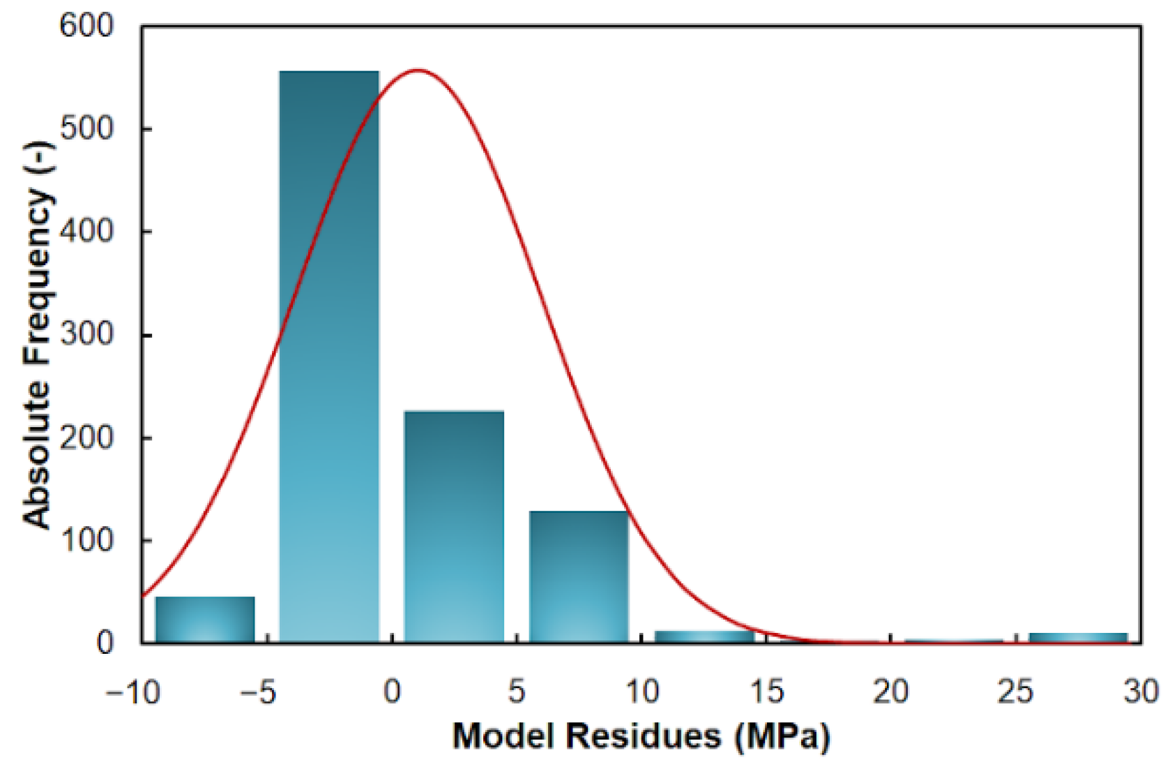
The above-mentioned favorable values of RMSE and R parameters are further supported by the histogram, showing the distribution of residuals of the Hensel–Spittel rheology law (Equation (1)), depicted in Figure 2. As can be observed, the model deviations from the experimental data were mostly lower than 5 MPa (a negligible number of residues exceeded the limit of 10 MPa, with the maximum of 30 MPa). However, further analysis of the residuals showed that such high deviations were exclusively associated with very low true strain values (below ~0.025). This corresponds to the very beginning of the deformation process and, therefore, does not fundamentally affect the accuracy of the calculations.
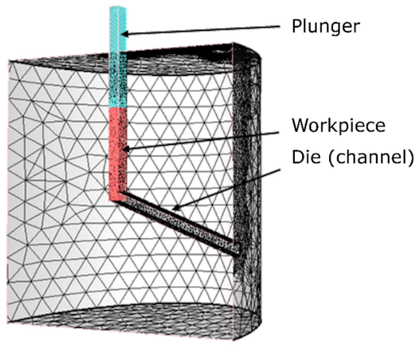
The assembly of the room temperature ECAP process for the numerical simulation, i.e., channel (die), workpiece (billet), and plunger, is depicted in Figure 3. The initial dimensions of the workpiece were 10 × 10 × 100 mm3, the dimensions of the plunger were 10.05 × 10.05 × 110 mm3, and the cross-section of the channel was 10.1 × 10.1 mm2, with the bending angle of 110°, all corresponding to the real experimental setup. The entire die was a cylinder with the diameter of 300 mm and height of 300 mm. The workpiece was considered as a deformable body, while both the tools (die, plunger) were considered as rigid bodies. Correspondingly, the die and plunger were surface-meshed, while the workpiece, defined with tetrahedron elements, was volume-meshed. The mesh of the workpiece consisted of a total of 13,128 nodes connecting 61,271 elements, while the meshes of the plunger and channel consisted of 2120 and 4652 nodes connecting 4236 and 9304 elements, respectively. To increase the efficiency and reduce the time required to calculate the simulations, anisotropic mesh was chosen, i.e., finer meshes were selected for the workpiece, and die locations of primary interest (Figure 3). As for the die, the channel part, being in a direct contact with the workpiece, was finely meshed, similar to the lower part of the plunger. Based on our previous experience with numerical simulations of SPD processes, the re-meshing procedure was activated.
The initial temperature of the workpiece, as well as of the die, plunger, and the ambient environment, was 20 °C. The temperature conditions were based on the conditions of the real ECAP process, which was performed at room temperature, without any preheating. The thermal exchange between the equipment, i.e., steel die and plunger, and the workpiece was determined by a heat transfer coefficient α of 10 000 W·m−2·K−1, and tool effusivity E of 11,764 J·m−2·K−1·s−1/2 (interface with the rigid die). The surrounding environment was set as air, and the thermal exchange between the assembly and the environment was characterized by a heat transfer coefficient α of 10 W·m−2·K−1, which corresponds to the assumption of free convection in the surroundings. Considering the fact that the ECAP process is a bulk forming process, and taking into account our previous experience, the combined (Coulomb and Tresca) friction law was selected. The friction between the tools and the workpiece was determined using a friction coefficient µ of 0.05 and friction factor m of 0.1. The movement of the plunger was controlled by a hydraulic press with the speed rate of 1 mm·s−1.
In the following section, the results of the numerical simulations performed for the Cu-La2O3 composite and, for comparison, for CP Cu are represented as graphical depictions of the distributions of the parameters of interest, i.e., temperature, effective strain, material plastic flow, stress state, and punch load. For the purposes of more detailed investigations of selected parameters, a monitoring plane was created along the longitudinal cross-sectional cut through the workpiece, and three individual sensors were located on this plane. Figure 4a shows that sensor 1 was located on one (top) workpiece surface, sensor 2 was located in the axis (i.e., middle of workpiece thickness), and sensor 3 was located at the opposite (bottom) surface of the extruded workpiece. Furthermore, a superimposed grid defined with square cells with the dimensions of 0.5 × 0.5 mm2 was created in the monitored plane to observe the material plastic flow (Figure 4b).

3. Results and Discussions

3.1. Experimental Analysis

3.1.1. Mechanical Behavior

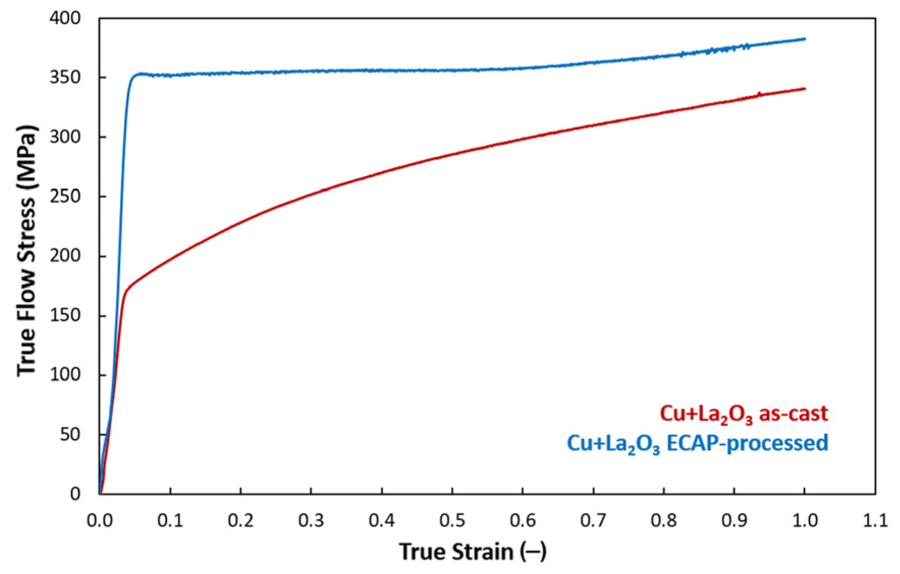
The results of the compression tests performed for both the Cu-La2O3 composites (as-cast and ECAP-processed) at the strain rate of 0.01 s−1 are depicted as the true flow stress–true strain curves in Figure 5. The figure shows that the maximum flow stress, achieved at the true strain of 1.0, was 340 MPa for the as-cast composite, and reached to 382 MPa for the ECAP-processed one. The difference in the maximum values was thus approximately 13%. Nevertheless, the behaviors of both the material states during the loading differed significantly. The as-cast composite exhibited a steep increase in the flow stress up to the value of ~170.4 MPa (true strain of 0.37). After reaching this value, the increase continued, but in a more gradual manner. On the other hand, the ECAP-processed composite exhibited a rapid increase in the flow stress up to the value of ~352.5 MPa (true strain of 0.055). With continuing deformation, the material exhibited more or less steady state like behavior. The rapid increase in flow stress observed at the very beginning of deformation for both the investigated material states can be attributed to rapid work hardening due to the presence of oxide particles acting as effective barriers for dislocations movement (introducing dislocations pinning and pile-ups) [17]. The acquired results can be compared to those acquired by Zhang et al. [79], who investigated the compressive strengths of Cu with additions of Y2O3 of 4, 7, and 10 wt.%. The compressive yield strengths achieved herein were 274, 438, and 613 MPa, respectively. Considering that the composite features presented herein were 5 wt.% of La2O3, the strengthening effect can be considered comparable to that of Y2O3. However, adding La2O3 is more favorable as it is less costly and generally features better room temperature conductivity than Y2O3 [80]. The very high initial increase in flow stress observed for the ECAP-processed composite studied herein can be attributed to the deformation history, i.e., to the ECAP-processing introducing numerous lattice defects, substructure development, and accumulation of dislocations (primarily at subgrain boundaries and oxide particles, as further discussed). It also confirms the highly favorable effect of La2O3 on dislocations pinning during deformation.
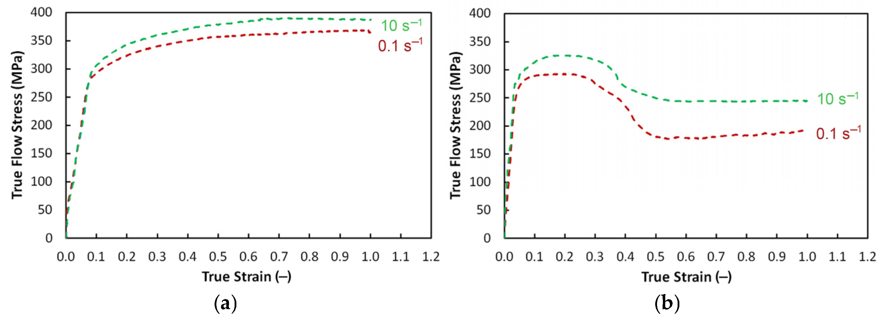
The fact that the microstructures and mechanical properties of SPD-processed materials are strongly dependent on temperature is known [81,82,83]. In this respect, thermal stability of the ECAP-processed composite under various thermomechanical conditions was further investigated. Figure 6a depicts the true flow stress–true strain curves acquired at the strain rates of 0.1 s−1 and 10 s−1 for the ECAP-processed composite, while Figure 6b depicts the true flow stress–true strain curves at identical strain rates for the ECAP-processed composite further subjected to the 250 °C/30 min heat treatment.
As can be seen in Figure 6a, the samples taken from the ECAP-processed composite with no heat treatment exhibited very similar deformation behaviors regardless the applied strain rate. This points to a relatively high stability of the ECAP-processed composite at room temperature. The fact that higher values of flow stress were achieved for the higher strain rate of 10 s−1 corresponds to: (i) the general hypothesis applicable for deformation processing of the majority of metallic alloys, (ii) the presence of La2O3 particles. In other words, the increased flow stress was related to: (i) the aggravated conditions for possible development of dynamic restoration processes given by speeding up the process of plastic deformation (i.e., work hardening dominated over dynamic restoration) [84], as well as (ii) increased frequency of interactions between dislocations and oxide particles during the (substantial) work hardening. As can be seen in Figure 6a, both the flow stress curves exhibited slight but continuous increases after reaching the strain value of 0.1 s−1. In other words, work hardening, supported by the intense dislocations pinning effect of the reinforcing oxide particles, dominated over dynamic softening (recovery) within the ECAP-processed composite under all the examined strain rates.
Figure 6b then documents that the applied heat treatment significantly influenced the deformation behavior of the ECAP-processed composite. The work hardening was significant already at the beginning of testing, and was visibly more progressive than in the case of the ECAP-processed composite with no heat treatment (compare Figure 6a,b, the flow stress curves in the latter exhibited steeper increases). Despite the fact that both the examined material states achieved similar flow stress values at the true strains at which deformation softening occurred, the deformation behaviors differed entirely. After reaching the peak stress, both the flow stress curves exhibited plateaus, followed with flow stress decreases. Such behavior confirmed the occurrence of dynamic softening, i.e., dynamic recrystallization. Although the applied heat treatment temperature of 250 °C was relatively low to trigger dynamic recrystallization, the process was initiated by the accumulated energy (severe strain imposed during ECAP), which lowered the necessary activation temperature [84]. Figure 6b also shows that the flow stress curve acquired for the strain rate of 0.1 s−1 exhibited a more significant decrease compared to that acquired for 10 s−1, i.e., softening was more prominent at the lower strain rate. This finding can be attributed to the differences in the mutual effects of work hardening and subsequent heat treatment and can be explained by similar phenomena as above, i.e., by speeding up the deformation process, the conditions for possible development of dynamic restoration were aggravated. It confirms the results acquired for the ECAP-processed composite with no heat treatment, and is in accordance with the above-mentioned hypothesis.

3.1.2. Vickers Microhardness

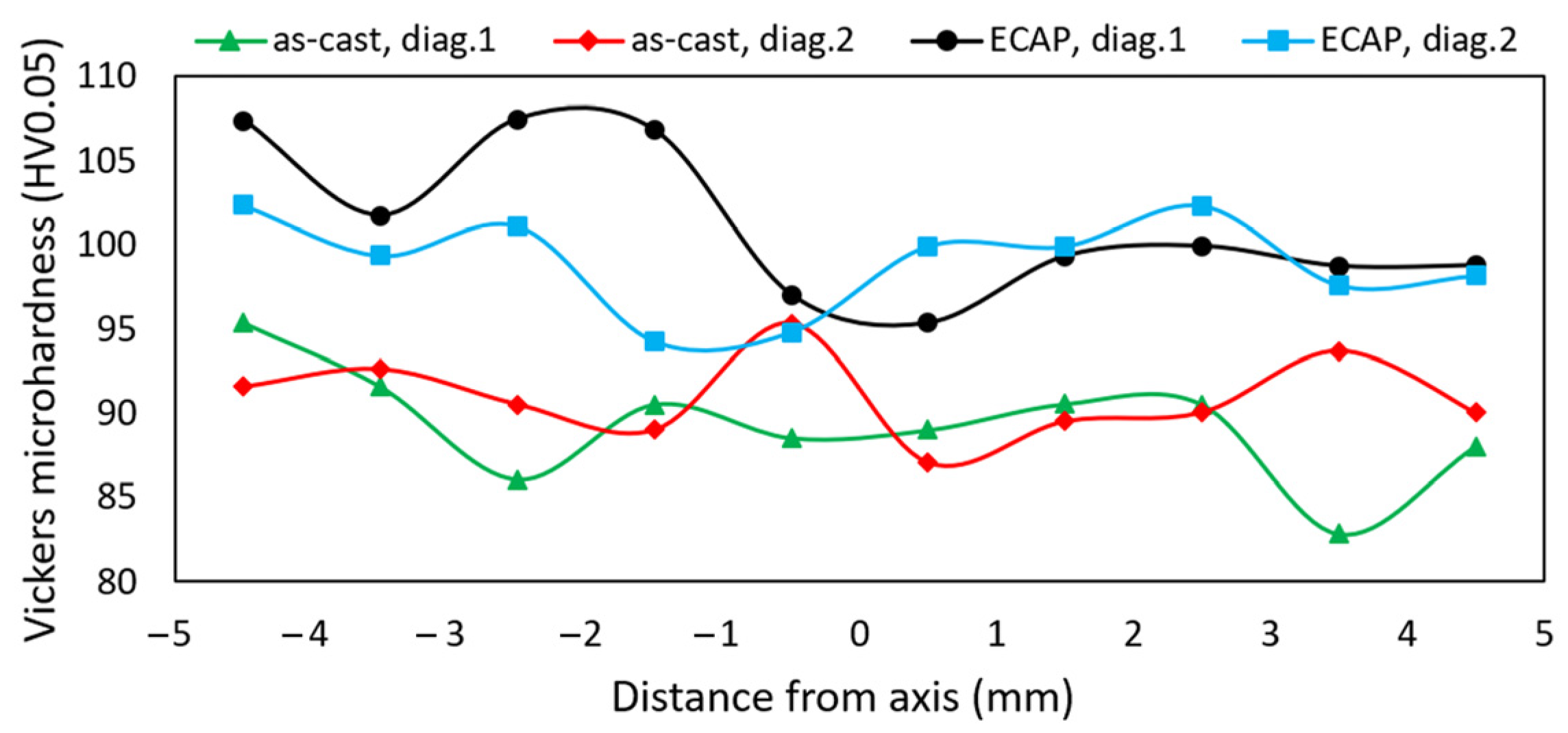
The average Vickers microhardness, measured for the CP Cu used to fabricate the Cu-La2O3 composite, was 46.2 HV0.05. The results of measurements of Vickers microhardness for the cross-sectional samples taken from both the as-cast and ECAP-processed composites are summarized in Figure 7. The measurements were performed along the intersecting diagonals across the cross-sections of the workpieces, as depicted in Figure 1. The as-cast Cu-La2O3 composite featured the average microhardness value of 90.1 HV0.05, which represents almost a 100% increase when compared to the original CP Cu. As shown in Figure 7, the diagonal trends across the cross-section of the as-cast composite were more or less random. In other words, the as-cast composite did not feature any clear decreasing/increasing trend in the microhardness across the cross-section, neither did it exhibit any severe local HV drops/increases, which would point to the presence of clusters of oxide particles.
The average Vickers microhardness value for the composite processed via a single pass ECAP increased to 100.6 HV0.05, which is another increase by more than 10% compared to the as-cast composite, and more than 120% increase when compared to the original CP Cu. Contrary to the as-cast composite, the microhardness values measured across the cross-section of the ECAP-processed composite exhibited a decreasing trend towards the bottom edge of the workpiece. In other words, the microhardness exhibited a trend specific for ECAP processing: the composite processed via ECAP exhibited increased microhardness values primarily in its (sub)surface region, in the vicinity of the top edge of the billet [54,85]. This phenomenon, which will further be discussed also in correlation with the results from the numerical simulations, can primarily be attributed to the influence of friction between the (sub)surface material layers and ECAP die. By the effect of friction, the material plastic flow was aggravated in this region, and thus the grains sheared and fragmented significantly therein. This effect was supported even more by the presence of oxide particles pinning the occurring and moving dislocations. These factors resulted in the observed microhardness increase (especially in the top workpiece region). Towards the bulk volume of the ECAP-processed composite, the effect of friction gradually mitigated. Therefore, the microhardness values gradually decreased, then remained more or less constant with no excessive deviations throughout the cross-section.
The phenomenon of cross-sectional inhomogeneity can be reduced by several approaches, one of which is applying multiple ECAP passes [86,87,88]. Another one is incorporating another feature in the die, such as when applying the twist channel (multi) angular pressing method (TCAP, TCMAP) [62,89]. These approaches were proven to successfully improve the homogeneity of the effective imposed strain across the cross-section of an ECAP-processed workpiece.

3.1.3. Microstructure

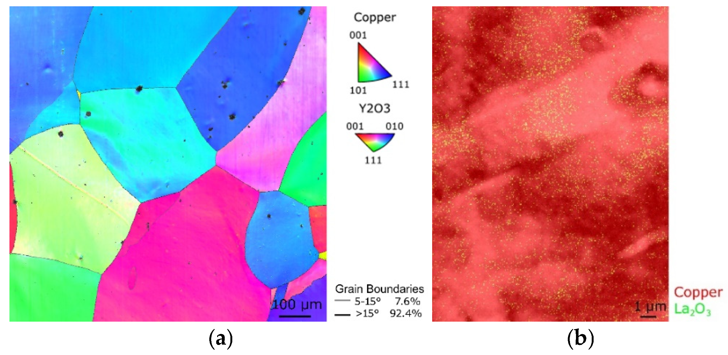
The microstructure of the as-cast Cu-La2O3 composite was analyzed at first. The Orientation Image Map (OIM) depicted in Figure 8a shows that the microstructure of the as-cast composite consisted of coarse equiaxed grains featuring a major fraction (more than 90%) of HAGB. The arithmetic mean grain size for the as-cast composite (measured as equivalent circle diameter) reached up to 190 µm, and the grains exhibited no dominant preferential orientations. Figure 8b, showing a detailed phase map of the as-cast composite, depicts that the distribution of the La2O3 particles within the Cu grains was more or less homogeneous. The homogeneity of the as-cast microstructure was documented by the stress–strain curve (Figure 5) and microhardness (Figure 7) acquired for the as-cast material state, both of which exhibited homogeneous trends with no obvious discrepancies (which could be caused by possibly present inhomogeneities or casting defects).
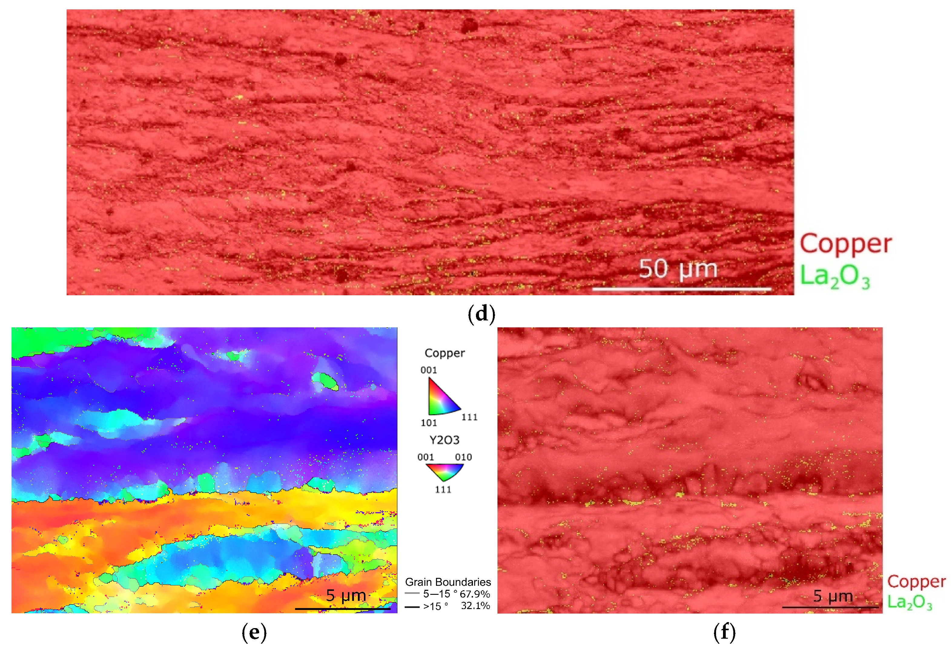
Figure 9a shows the OIM image of the microstructure of the ECAP-processed Cu-La2O3 composite. As can be seen, a single ECAP pass imparted substantial changes in the micro and substructure. The grains, which were more or less randomly oriented after casting, exhibited the tendency to form typical <111> || SD (shear direction) shear texture fiber already after the single pass ECAP; see also the Inverse Pole Figures (IPF) depicting texture orientations and texture intensity in Figure 9b. The fraction of LAGB changed remarkably, too, and increased from a negligible value observed before ECAP-processing up to more than 17%. Both tendencies—to form substructure (increase in the fraction of LAGBs) and texture fibers—can be attributed to the fact that the La2O3 particles acted as effective obstacles and hindered the movement of dislocations [17,52]. This hypothesis was confirmed by subsequent detailed observations, which revealed the presence of shear bands within the ECAP-processed Cu grains. Figure 9c depicts the OIM map showing a more detailed view on the microstructure of the ECAP-processed composite, while the OIM image in Figure 9e shows a very close view depicting the substructure. Both the Figures clearly show the presence of dislocation walls and developing subgrains in the shear bands within a single grain affected by the ECAP processing. Sousa et al. [90] previously reported that a single ECAP pass is able to increase the dislocations density within pure Cu to more than 1 × 10¹². Such an increase in dislocations density imparted by ECAP, together with the presence of La2O3 particles, non-negligibly resulted in the intense strain hardening, as documented in Section 3.1.1 and Section 3.1.2. As revealed by the phase map depicted in Figure 9d, as well as by the very detailed phase map shown in Figure 9f, (the close vicinity of) the shear band boundaries exhibited the presence of (increased volume fractions) the oxide particles. In other words, the analysis confirmed that the presence of La2O3 particles supported the development of substructure and shear banding within the composite workpiece during ECAP processing (both of which contributed to increase in the mechanical properties, as discussed above). The experimentally acquired results on microstructures and mechanical properties are further put in correlation with the overall material behavior, which was examined via a numerical simulation (Section 3.2).

3.2. Numerical Prediction

3.2.1. Deformation Temperature

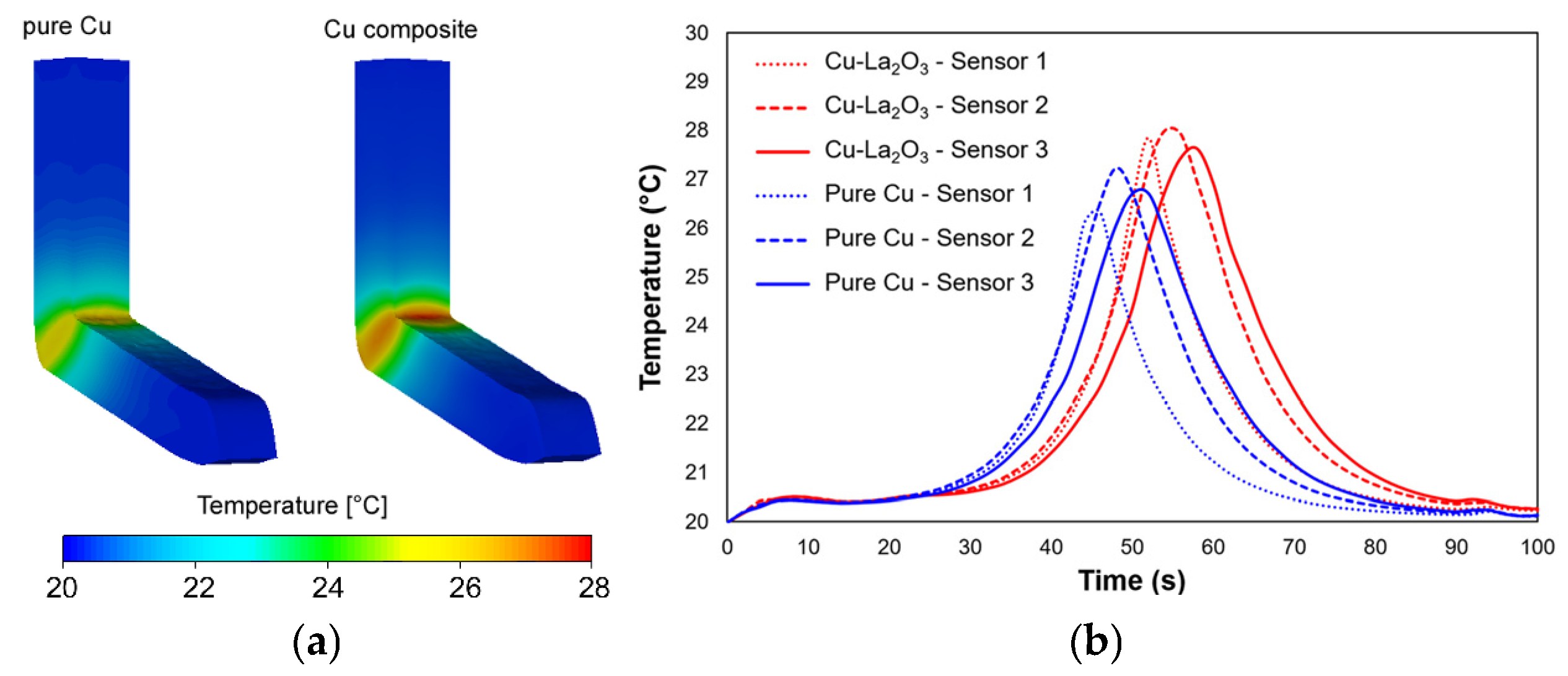
The predicted developments of deformation temperature within the Cu-La2O3 composite and CP Cu during the ECAP process are depicted in Figure 10a. Both the workpieces clearly exhibited slight increases in temperature in the region of the main deformation zone (i.e., passage through the channel bending). For both the investigated materials, this phenomenon can be attributed to the development of deformation heat, see, e.g., [85,89]. However, the Figure also demonstrates that this increase was more intense (approximately by 20%) for the composite with La2O3 particles than for the CP Cu. This finding is in accordance with the expected substantial development of dislocations during ECAP processing, and also confirms that the presence of the oxide particles contributed to a more intense work hardening within the composite.
As regards the bulk volume of an extruded workpiece, the highest temperature was detected in sensor 2 (i.e., in the vicinity of workpiece axis) for both the investigated materials; see Figure 10b depicting the developments of temperature in time of extrusion for both the CP Cu and Cu-La2O3. This result is in agreement with the localization of the main deformation zone in the ECAP die, the simple shear in which is the most intense, and, simultaneously, temperature transfer into the die is the most aggravated, also due to the occurrence of the dead zone (Section 3.2.5).

3.2.2. Effective Strain

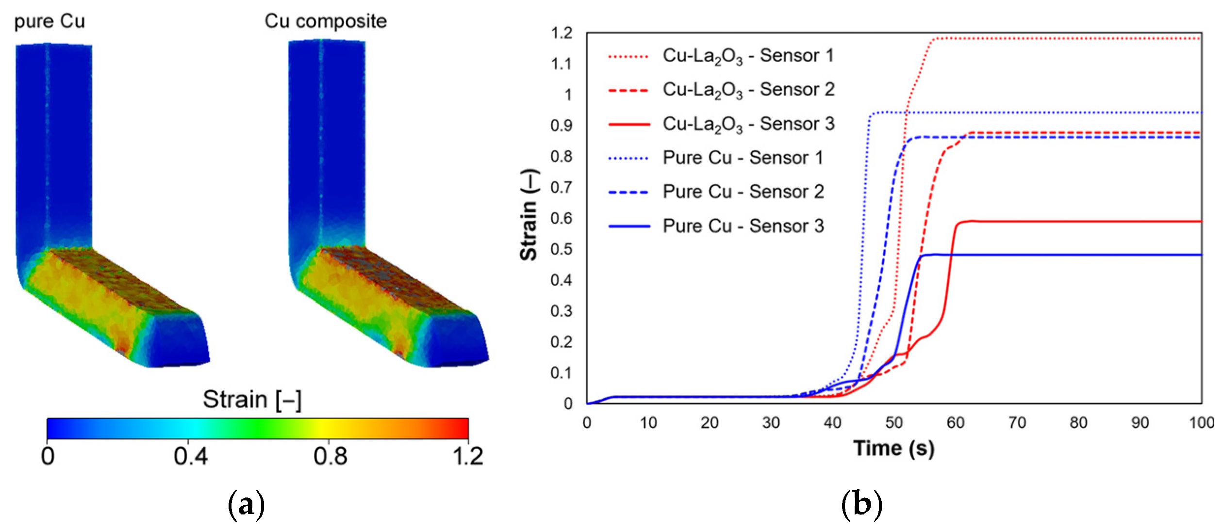
Figure 11a depicts the distributions of the effective imposed strain within both the CP Cu and Cu-La2O3 composite during ECAP processing. Similar to the distributions of deformation temperature, both the extruded workpieces exhibited increased imposed strain after passing through the main deformation zone of the die. Figure 11b shows gradual increases in strain over time in the individual sensors for both the materials; such development corresponded to gradual approaching of a workpiece (location with the sensors) to the main deformation zone. Entering of a workpiece (i.e., location with sensors) to the main deformation zone was then accompanied with a rapid increase in the effective imposed strain. Further, as the workpiece passed through the channel bending zone, the effective imposed strain remained more or less constant. However, the differences between both the processed workpieces were evident.
Primarily, the increase in strain was again greater for the composite than for CP Cu, in all the monitored sensors. In other words, the predicted maxima of the effective imposed strain were higher for the Cu-La2O3 composite. This finding was in accordance with: (i) the experimental results and above-mentioned hypotheses on dislocations development and work hardening, and (ii) the fact that the values of the strain hardening/softening constants acquired for the reliable fit of the Hensel–Spittel model (Equation (1)) for the Cu-La2O3 composite pointed to a more significant work hardening when compared to CP Cu. Also, during the processing, two interesting phenomena were noticed. The first one was that the increase in the effective strain in time was quicker for the composite than for the CP Cu. In other words, the Cu-La2O3 composite exhibited a more rapid increase in the imposed strain in all the examined locations than CP Cu, which was confirmed by steeper growths of the curves at the time of 40–60 s, see Figure 11b. This phenomenon can be attributed to the rapid work hardening of the composite, as also documented by the experimentally acquired data (Section 3.1.1 and Section 3.1.2). The second intriguing phenomenon was that sensor 1 for the CP Cu generally exhibited slightly lower increase in the effective imposed strain than sensors 2 and 3. The effective imposed strain in the top (sub)surface region of the composite (sensor 1) thus achieved a higher maximum value (by ~20%) when compared to CP Cu. This phenomenon again points to intense dislocations development and work hardening of the composite. However, it also points to a certain inhomogeneity of the imposed strain across the cross-section of the workpiece.
The cross-sectional inhomogeneity can be explained by the material plastic flow, i.e., the paths the atoms (crystallites) take during passing through the ECAP channel (see also Section 3.2.5 on plastic flow). The strain imposed during ECAP processing generally tends to be the highest along the top surface (sensor 1) of a workpiece, as the paths of the crystallites in the (very) vicinity of the top workpiece–die interface are the shortest [54,85]. Towards the longitudinal axis of a workpiece (sensor 2) the paths of the crystallites lengthen, and are the longest along the bottom workpiece surface, in the (very) vicinity of the bottom workpiece–die interface (sensor 3). For this reason, the effective imposed strain generally tends to be higher along the top surface of a processed workpiece than along its bottom surface. The inhomogeneity can also be affected by friction (i) and (ii) die bending angle. (i) The effect of friction, aggravating the material plastic flow at the workpiece–die interface, diminishes towards the bulk of the processed workpiece [91,92]. (ii) Die angles higher than 90° are generally preferred for processing of materials with low formability, such as Mg-based ones [56,93], or materials for which a high hardening rate is expected, such as the Cu-La2O3 composite. On the other hand, increasing the die bending angle generally decreases the maximum imposed strain achievable within a single pass, and increases the cross-sectional inhomogeneity [94,95].
The predicted results went hand in hand with the experimentally observed inhomogeneity in microhardness (Section 3.1.2). Nevertheless, the absolute value of the imposed strain is dependent on the particular material behavior. Note that the difference in the imposed strain between sensor 1 and sensor 2 was substantially higher for the composite than for the CP Cu, Figure 11b. The most probable reason for this was the presence of oxide particles imparting differences in the material plastic flow, as further discussed in detail. The presence of the oxide particles introduced the above-mentioned work hardening, modified the effectivity of the acting simple shear deformation mechanism and consequently changed the plastic flow, i.e., depth of penetration of the imposed strain into the bulk of the workpiece. The comparisons of the predicted effective imposed strain for both the CP Cu and Cu-La2O3 composite depicted in Figure 11a,b document that the latter exhibited a higher hardening rate during ECAP processing, although the inhomogeneity typical for materials processed with a single pass ECAP could be observed for both.

3.2.3. Stress Distribution

The predicted distribution of von Mises stress depicted in Figure 12a shows evident differences between the two ECAP-processed materials. The Cu-La2O3 composite exhibited the maximum stress of up to 600 MPa when passing through the main deformation zone, which was by up to 50% higher than the maximum stress predicted for the CP Cu. This indicates that the Cu-La2O3 composite required a (much) greater punch load to be successfully deformed by the ECAP process than CP Cu (see also Section 3.2.4). This finding supported the experimentally acquired results and confirmed that the addition of La2O3 particles has a highly strengthening effect on Cu. When compared to the CP Cu, the Cu-La2O3 composite exhibited notable increase in stress, especially in the vicinity of the top workpiece–die interface. Similar to the effective strain distribution, the stress distribution corresponds with the observed cross-sectional inhomogeneity of mechanical properties, as documented in Section 3.1.3.
Figure 12b depicts predicted residual stress within the ECAP-processed workpieces. As evident from the Figure, the maximum values of both the tensile and compressive stress were substantially higher (by more than 20%) for the composite than for the CP Cu. Interestingly, the majority of the volume of the ECAP-processed composite exhibited tensile residual stress, while the processed CP Cu featured predominantly compressive residual stress. The presence of tensile stress is related to a higher risk of occurrence of cracks during processing. In this respect, processing of the composite via ECAP can be considered to be more problematic than ECAP processing of CP Cu. With a high probability, the presence of tensile residual stress originated from the presence of a highly effective mechanism of work hardening introduced by the oxide particles.

3.2.4. Punch Load

Among the very important parameters characterizing deformation processing is the force that needs to be applied for the process to be successfully performed. In case of ECAP processing, the punch load parameter is crucial for the choice of a suitable extrusion machine, as well as for determination of punch stability and durability. Figure 13 shows that the necessary load for ECAP processing of the Cu-La2O3 composite can be up to 30% higher in comparison with ECAP processing of CP Cu. In addition, two distinct differences can be noticed. First, processing of the composite featured a substantially higher increase in the load force than processing of the CP Cu at the moment of entering/crossing the main deformation zone (time of extrusion ~15 s). Second, contrary to the punch load predicted for the CP Cu, the load predicted for the composite featured a final increase at the very end of processing. The most probable reason for these differences was the presence of the oxide particles and their influence on the work hardening; the oscillations on both the curves are typically related to instability of material plastic flow, which, again, goes hand in hand with work hardening. The punch load is another factor supporting the experimentally acquired results and predicted differences between both the examined materials.

3.2.5. Plastic Flow

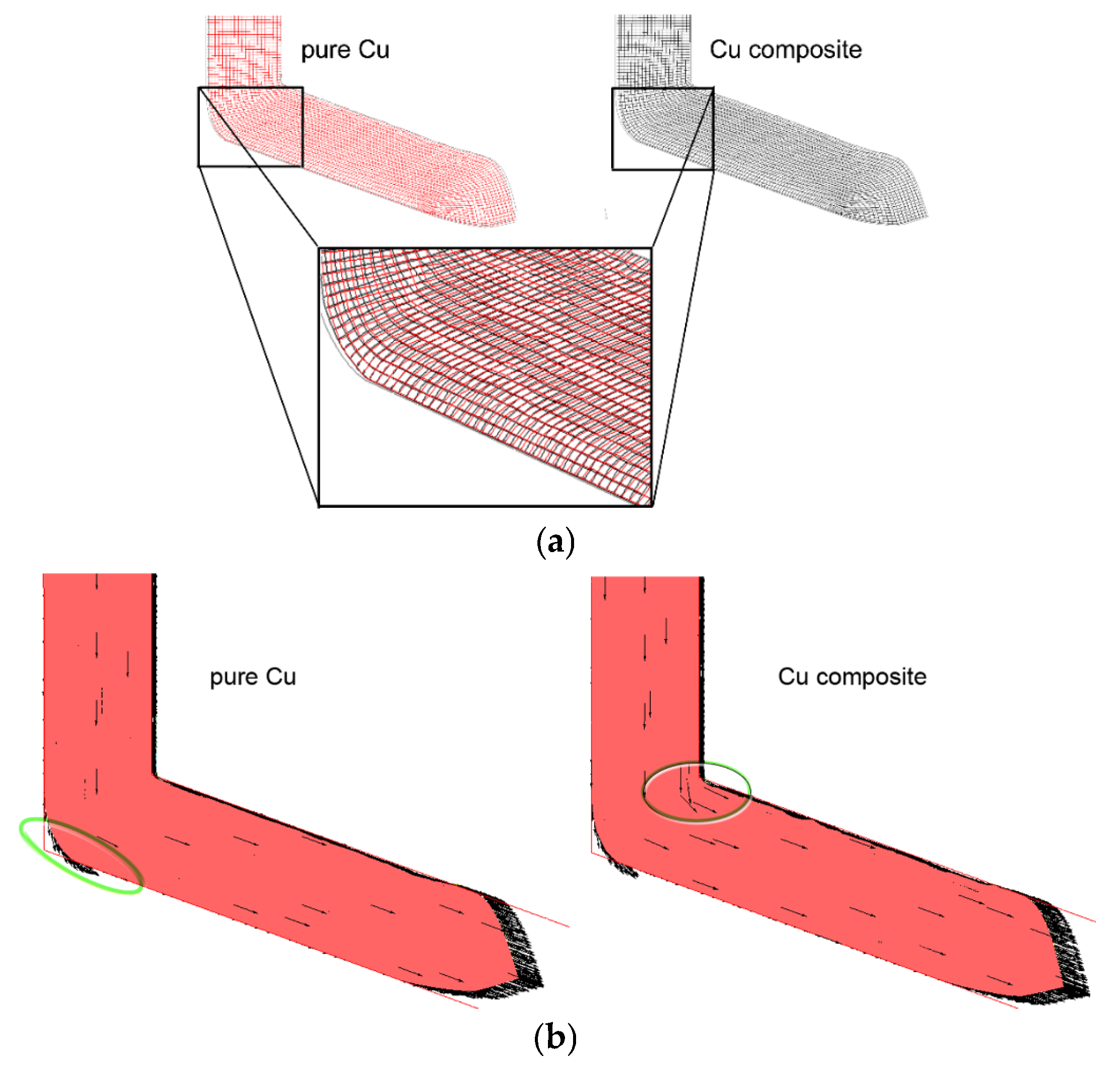
The (differences in the) material plastic flows of both the processed materials were the primary reasons for/consequences of the majority of the above discussed differences observed during the simulation, as well as experiment. At first, the predicted plastic flow was evaluated using the superimposed grid (see Figure 14a). The grid clearly shows the differences in the intensity of forward material flow of the Cu-La2O3 composite and CP Cu. The original square cells of the grids within both the workpieces were deformed by the effect of simple shear. However, the effect of the oxide particles, acting as effective obstacles for dislocations movement and thus aggravating the forward plastic flow, is clearly visible in Figure 14a. In case of CP Cu, a more complicated material plastic flow can be expected as this material features (virtually) no obstacles, such as precipitates and oxide particles (pure metals tend to exhibit more “turbulent” plastic flows than alloys or composites), e.g., [89]. On the other hand, the material plastic flow of the Cu-La2O3 composite exhibited the tendency to delay, particularly along the top and bottom interfaces. This was primarily caused by the effect of friction and intense work hardening in these regions. The plastic flow was aggravated already in the main deformation zone (the transverse lines of the grid within the CP Cu evidently moved faster than those within the composite). This phenomenon also directly affected the size of the dead zone, i.e., the zone in the corner of the bending channel, the workpiece in which was not in contact with the channel wall. The dead zone was thus larger when processing CP Cu than the composite, see Figure 14a,b. Increasing the size of the dead zone generally results in a higher heterogeneity of the imposed strain [96]. As can be seen from the comparison of the imposed strains for both the workpieces (Figure 11b), the material plastic flow predicted within this study is in accordance with this hypothesis. Figure 14b then shows that the velocity of the material plastic flow of the composite tended to decelerate in the main deformation zone. The plastic flow vectors in the bulk of the composite changed their directions, particularly in the area of the inner corner of the die channel. In other words, the plastic flow within the composite exhibited a tendency to flow towards the outer corner of the die, contrary to CP Cu. By this effect, the size of the dead zone decreased during ECAP processing of the composite (see Figure 14b).
Considering the results acquired from the experimental investigation and numerical simulation of a vacuum induction cast Cu-La2O3 composite processed via a single pass ECAP and their mutual correlation, the conclusion that such a composite could be manufactured by the proposed method in commercial conditions can be drawn. The designed composite could be used to manufacture little durable components, such as specific components in the microelectronics, and their final properties could be tailored by modifying and optimizing the processing conditions, especially when considering wider processing possibilities, such as the application of TC(M)AP or multiple pass ECAP. Nevertheless, in order to tailor and optimize the properties of such a Cu-La2O3 composite for application in the microelectronics, the relation of processing conditions and electric conductivity should be further investigated. Our prospective research is going to involve a study of the effects of ECAP processing by multiple passes via various deformation routes on the homogeneity of the imposed strain across the cross-sections of Cu-La2O3 composite workpieces, in correlation with the electric properties.

4. Conclusions

The study involved experimental and numerical examination of an innovative Cu-based composite with 5 wt.% addition of La2O3, processed by equal channel angular pressing (ECAP) through a 110° die. The most important results were:
-
La2O3 hindered movement of dislocations and supported the development of shear bands and substructure during ECAP; their presence promoted formation of <111>||SD texture.
-
ECAP processing caused accumulation of dislocations and consequently increased the maximum flow stress of the composite to 382 MPa, average Vickers microhardness increased by 120% compared to CP Cu.
-
the composite exhibited substantial work hardening, which increased the effective imposed strain, but at the expense of tensile residual stress and increased punch load; the presence of La2O3 directly influenced the size of the dead zone in the ECAP die.
-
the energy accumulated during ECAP decreased the activation energy for dynamic recrystallization and influenced thermal stability of the mechanical properties.
The acquired results document that the ECAP method is highly promising for preparation of Cu-based composites with enhanced mechanical properties. The observed inhomogeneities introduced by the ECAP process can be overcome by optimized additional deformation processing (e.g., using multiple ECAP passes).

Author Contributions

Conceptualization, data curation, investigation, writing—original draft preparation: L.K.; investigation, project administration, funding acquisition, software, writing—review and editing: R.K. All authors have read and agreed to the published version of the manuscript.

Funding

The authors acknowledge the support of project no. 25-16860S by the Czech Science Foundation.

Data Availability Statement

The original data supporting the research are available upon a reasonable request from the corresponding author.

Acknowledgments

We would like to thank Petr Opěla and Josef Walek (Department of Metallurgical Technologies, VŠB-Technical University of Ostrava) for their assistance.

Conflicts of Interest

The authors declare no conflicts of interest. The funders had no role in the design of the study, in the collection, analyses, or interpretation of data, in the writing of the manuscript, or in the decision to publish the results.

References

  1. Russell, A.; Lee, K.L. Structure-Property Relations in Nonferrous Metals, 1st ed.; John Wiley & Sons, Inc.: Hoboken, NJ, USA, 2005; ISBN 978-0-471-64952-6. [Google Scholar]
  2. Konchakova, I.S.; Kolmakov, A.G.; Gvozdev, A.E. Features of the Influence of Thermal Action on Structural Changes in Copper Conductors. Inorg. Mater. Appl. Res. 2021, 12, 993–999. [Google Scholar] [CrossRef]
  3. Gilev, V.G.; Bezmaternykh, N.V.; Morozov, E.A. Study of Steel–Copper Pseudo Alloy Microstructure and Microhardness After Laser Heat Treatment. Met. Sci. Heat Treat. 2014, 56, 262–268. [Google Scholar] [CrossRef]
  4. Chu, Z.Q.; Wei, K.X.; Wei, W.; Alexandrov, I.V.; An, X.L.; Wang, D.D.; Liu, X.K. Simultaneously Enhancing Mechanical Properties and Electrical Conductivity of Cu-0.5%Cr Alloy as 5G Connector Material. J. Alloys Compd. 2023, 948, 169750. [Google Scholar] [CrossRef]
  5. Kocich, R.; Kunčická, L. Crossing the Limits of Electric Conductivity of Copper by Inducing Nanotwinning via Extreme Plastic Deformation at Cryogenic Conditions. Mater. Charact. 2024, 207, 113513. [Google Scholar] [CrossRef]
  6. Popovich, A.; Sufiiarov, V.; Polozov, I.; Borisov, E.; Masaylo, D.; Orlov, A. Microstructure and Mechanical Properties of Additive Manufactured Copper Alloy. Mater. Lett. 2016, 179, 38–41. [Google Scholar] [CrossRef]
  7. Wu, Y.; Zhang, W.; Li, Y.; Yang, F.; Liu, H.; Zou, J.; Jiang, J.; Fang, F.; Ma, A. An Overview of Microstructure Regulation Treatment of Cu-Fe Alloys to Improve Strength, Conductivity, and Electromagnetic Shielding. J. Alloys Compd. 2024, 1002, 175425. [Google Scholar] [CrossRef]
  8. Kunčická, L.; Kocich, R. Effect of Activated Slip Systems on Dynamic Recrystallization during Rotary Swaging of Electro-Conductive Al-Cu Composites. Mater. Lett. 2022, 321, 10–13. [Google Scholar] [CrossRef]
  9. Hu, X.; Hu, H.; Lai, R.; Xie, Q.; Zhi, Y. Cyclic Warm Rolling: A Path to Superior Properties in Mo Cu Composites. Int. J. Refract. Met. Hard Mater. 2025, 126, 106926. [Google Scholar] [CrossRef]
  10. Strunz, P.; Kunčická, L.; Beran, P.; Kocich, R.; Hervoches, C. Correlating Microstrain and Activated Slip Systems with Mechanical Properties within Rotary Swaged WNiCo Pseudoalloy. Materials 2020, 13, 208. [Google Scholar] [CrossRef]
  11. Kunčická, L.; Kocich, R.; Németh, G.; Dvořák, K.; Pagáč, M. Effect of Post Process Shear Straining on Structure and Mechanical Properties of 316 L Stainless Steel Manufactured via Powder Bed Fusion. Addit. Manuf. 2022, 59, 103128. [Google Scholar] [CrossRef]
  12. Canelo-Yubero, D.; Kocich, R.; Hervoches, C.; Strunz, P.; Kunčická, L.; Krátká, L. Neutron Diffraction Study of Residual Stresses in a W–Ni–Co Heavy Alloy Processed by Rotary Swaging at Room and High Temperatures. Met. Mater. Int. 2022, 28, 919–930. [Google Scholar] [CrossRef]
  13. Wang, Z.; Chen, J.; Kocich, R.; Tardif, S.; Dolbnya, I.P.; Kunčická, L.; Micha, J.-S.; Liogas, K.; Magdysyuk, O.V.; Szurman, I.; et al. Grain Structure Engineering of NiTi Shape Memory Alloys by Intensive Plastic Deformation. ACS Appl. Mater. Interfaces 2022, 14, 31396–31410. [Google Scholar] [CrossRef] [PubMed]
  14. Kunčická, L.; Kocich, R.; Ryukhtin, V.; Cullen, J.C.T.; Lavery, N.P. Study of Structure of Naturally Aged Aluminium after Twist Channel Angular Pressing. Mater. Charact. 2019, 152, 94–100. [Google Scholar] [CrossRef]
  15. Segal, V. Review: Modes and Processes of Severe Plastic Deformation (SPD). Materials 2018, 11, 1175. [Google Scholar] [CrossRef]
  16. Arbuz, A.; Lutchenko, N.; Yordanova, R. FEM Method Study of the Advanced ECAP Die Channel and Tool Design. Modelling 2025, 6, 19. [Google Scholar] [CrossRef]
  17. Verlinden, B.; Driver, J.; Samajdar, I.; Doherty, R.D. Thermo-Mechanical Processing of Metallic Materials; Elsevier: Amsterdam, The Netherland, 2007; ISBN 9780080444970. [Google Scholar]
  18. Bodyakova, A.; Tkachev, M.; Raab, G.I.; Kaibyshev, R.; Belyakov, A.N. Regularities of Microstructure Evolution in a Cu-Cr-Zr Alloy during Severe Plastic Deformation. Materials 2022, 15, 5745. [Google Scholar] [CrossRef]
  19. Sukhov, I.A.; Shafeev, G.A.; Voronov, V.V.; Sygletou, M.; Stratakis, E.; Fotakis, C. Generation of Nanoparticles of Bronze and Brass by Laser Ablation in Liquid. Appl. Surf. Sci. 2014, 302, 79–82. [Google Scholar] [CrossRef]
  20. Muñoz, A.I.; Antón, J.G.; Guiñón, J.L.; Herranz, V.P. Corrosion Behavior and Galvanic Studies of Brass and Bronzes in Aqueous Lithium Bromide Solutions. Corrosion 2002, 58, 560–569. [Google Scholar] [CrossRef]
  21. Zhou, M.; Geng, Y.; Zhang, Y.; Ban, Y.; Li, X.; Jia, Y.; Liang, S.; Tian, B.; Liu, Y.; Volinsky, A.A. Enhanced Mechanical Properties and High Electrical Conductivity of Copper Alloy via Dual-Nanoprecipitation. Mater. Charact. 2023, 195, 112494. [Google Scholar] [CrossRef]
  22. Dubskii, G.A.; Vdovin, K.N.; Nefed’ev, A.A.; Egorova, L.G. Thermal Conductivity of Low-Alloy Copper for Molds. Russ. Metall. 2018, 2018, 252–258. [Google Scholar] [CrossRef]
  23. Tian, W.; Zhang, F.; Han, S.; Chen, X.; Gao, P.; Zheng, K. Analysis of Microstructure and Properties in Cold Rotary Swaged Copper-Clad Magnesium Wires. Metals 2023, 13, 467. [Google Scholar] [CrossRef]
  24. Volkov, A.Y.; Kalonov, A.A.; Zavalishin, V.A.; Glukhov, A.V.; Komkova, D.A.; Antonov, B.D. The Influence of Interfaces on the Physicomechanical Properties of Cu/Mg Composites. Phys. Met. Metallogr. 2020, 121, 568–574. [Google Scholar] [CrossRef]
  25. Volkov, A.Y.; Kalonov, A.A.; Komkova, D.A.; Glukhov, A.V. Structure and Properties of Cu/Mg Composites Produced by Hydrostatic Extrusion. Phys. Met. Metallogr. 2018, 119, 946–955. [Google Scholar] [CrossRef]
  26. Kocich, R.; Kunčická, L. Optimizing Structure and Properties of Al/Cu Laminated Conductors via Severe Shear Strain. J. Alloys Compd. 2023, 953, 170124. [Google Scholar] [CrossRef]
  27. Rogachev, S.O.; Sundeev, R.V.; Andreev, V.A.; Andreev, N.V.; Tabachkova, N.Y.; Korotkova, N.O. The Microstructure and Conductivity of Copper–Aluminum Composites Prepared by Rotary Swaging. Phys. Met. Metallogr. 2022, 123, 1193–1200. [Google Scholar] [CrossRef]
  28. Zhang, X.; Yu, Y.; Liu, B.; Ren, J. Mechanical Properties and Tensile Fracture Mechanism Investigation of Al/Cu/Ti/Cu/Al Laminated Composites Fabricated by Rolling. J. Alloys Compd. 2019, 805, 338–345. [Google Scholar] [CrossRef]
  29. Popova, E.N.; Deryagina, I.L.; Valova-Zaharevskaya, E.G.; Ruello, M.L.; Popov, V.V. Microstructural Features in Multicore Cu–Nb Composites. Materials 2021, 14, 7033. [Google Scholar] [CrossRef]
  30. Permyakova, I.E.; Glezer, A.M.; Karpov, M.I.; Vnukov, V.I.; Shtansky, D.V.; Gorshenkov, M.V.; Schetinin, I.V. Structure Amorphization and Mechanical Properties of Nanolaminates of the Copper–Niobium System During High-Pressure Torsion. Russ. Phys. J. 2018, 61, 428–438. [Google Scholar] [CrossRef]
  31. Deryagina, I.L.; Popova, E.N.; Valova-Zaharevskaya, E.G.; Patrakov, E.I. Structure and Thermal Stability of High-Strength Cu–18Nb Composite Depending on the Degree of Deformation. Phys. Met. Metallogr. 2018, 119, 92–102. [Google Scholar] [CrossRef]
  32. Bokstein, B.S.; Vnukov, V.I.; Golosov, E.V.; Karpov, M.I.; Kolobov, Y.R.; Kolesnikov, D.A.; Korzhov, V.P.; Rodin, A.O. Structure and Diffusion Processes in Laminated Composites of a Cu–Ti System. Russ. Phys. J. 2009, 52, 811–815. [Google Scholar] [CrossRef]
  33. Liu, Z.; Wang, X.; Liu, M.; Liu, Y.; Liu, J.; Ignatov, A.V.; Wang, T. Microstructure and Mechanical Behavior of Ti/Cu/Ti Laminated Composites Produced by Corrugated and Flat Rolling. Trans. Nonferrous Met. Soc. China 2022, 32, 2598–2608. [Google Scholar] [CrossRef]
  34. Xu, Q.; Zhang, X.; Han, J.; He, X.; Kvanin, V.L. Combustion Synthesis and Densification of Titanium Diboride–Copper Matrix Composite. Mater. Lett. 2003, 57, 4439–4444. [Google Scholar] [CrossRef]
  35. Mali, V.I.; Bataev, A.A.; Maliutina, I.N.; Kurguzov, V.D.; Bataev, I.A.; Esikov, M.A.; Lozhkin, V.S. Microstructure and Mechanical Properties of Ti/Ta/Cu/Ni Alloy Laminate Composite Materials Produced by Explosive Welding. Int. J. Adv. Manuf. Technol. 2017, 93, 4285–4294. [Google Scholar] [CrossRef]
  36. Trykov, Y.; Gurevich, L.; Pronichev, D.; Trunov, M. Investigation of the Rupture of Ti/Steel Laminated Composite with Soft Interlayers. FME Trans. 2016, 44, 16–21. [Google Scholar] [CrossRef]
  37. Xu, W.; Qi, J.; Zhang, Y.; Zeng, G.; Zhou, Y.; Ou, H.; Zhou, H.; Wu, Y.; Yang, Y. Effect of Annealing Treatment on Electromagnetic Shielding Effectiveness of Double-Layer FeSiBCuNb/Cu Composite Strips. J. Mater. Sci. Mater. Electron. 2023, 34, 376. [Google Scholar] [CrossRef]
  38. Sheinerman, A.G.; Gutkin, M.Y. Multiple Cracking in Deformed Laminated Metal-Graphene Composites. Compos. Struct. 2018, 191, 113–118. [Google Scholar] [CrossRef]
  39. Zhao, Y.; Zhang, Y.; Wang, W.; Yue, S.; Li, T. A Novel Approach to Achieve High Strength, High Plasticity and High Conductivity of Graphene/Cu Composites with Graphene Core-Shell Structure. J. Alloys Compd. 2024, 1002, 175207. [Google Scholar] [CrossRef]
  40. Wei, K.X.; Jia, F.L.; Wei, W.; Zhou, H.R.; Chu, F.Q.; Du, Q.B.; Alexandrov, I.V.; Hu, J. Flexible Nanotwinned Graphene/Copper Composites as Thermal Management Materials. ACS Appl. Nano Mater. 2020, 3, 4810–4817. [Google Scholar] [CrossRef]
  41. Akmal, J.; Salmi, M. Additive Manufacturing of Self-Sensing Parts through Material Extrusion. Virtual Phys. Prototyp. 2024, 19, e2321200. [Google Scholar] [CrossRef]
  42. Koltsova, T.S.; Bobrynina, E.V.; Larionova, T.V.; Salynova, M.A.; Tolochko, O.V. Structure and Properties of Copper-Based Composite with Different Types of Carbon Nanostructures. Diam. Relat. Mater. 2022, 124, 108933. [Google Scholar] [CrossRef]
  43. Han, K.; Goddard, R.E.; Toplosky, V.; Niu, R.; Lu, J.; Walsh, R. Alumina Particle Reinforced Cu Matrix Conductors. IEEE Trans. Appl. Supercond. 2018, 28, 1–5. [Google Scholar] [CrossRef]
  44. Grigoreva, T.F.; Talako, T.L.; Devyatkina, E.T.; Vosmerikov, S.V.; Ancharov, A.I.; Tsybulya, S.V.; Vityaz, P.A.; Lyakhov, N.Z. Modifying Copper with Alumina during a Mechanically Stimulated Reaction. Phys. Met. Metallogr. 2023, 124, 74–79. [Google Scholar] [CrossRef]
  45. Volkova, I.R.; Tyryshkina, L.E.; Volochaev, M.N.; Zaloga, A.N.; Shabanova, K.A.; Ovchinnikov, A.V.; Lyamkin, A.I. The Effect of Aluminum-Oxide Powders on the Structure and Properties of Copper Electrodeposited Composite Coatings. Prot. Met. Phys. Chem. Surf. 2023, 59, 71–75. [Google Scholar] [CrossRef]
  46. Ma, B.; Ding, H.; Jiang, F.; Hishinuma, Y.; Luo, L.; Zhang, Y.; Wang, J.; Sheng, X.; Noto, H.; Liu, J.; et al. Effect of Process Control Agent on the Synthesis of Cu-Y2O3 by Mechanical Alloying. Nucl. Mater. Energy 2024, 38, 101599. [Google Scholar] [CrossRef]
  47. Huang, F.; Wang, H.; Yang, B.; Liao, T.; Wang, Z. Pinning Effect of Y2O3 Network on Copper Grain Growth during High Temperature Annealing. Mater. Res. Express 2018, 5, 056520. [Google Scholar] [CrossRef]
  48. Sobahi, N.; El-Kady, O.A.; Nouh, F.; Banoqitah, E.; Ghoname, R.; Moustafa, E.B.; Elsheikh, A. Impact of Nano-Y2O3 on the Physical, Microstructure, and Mechanical Characteristics of Cu Composite Fabricated via Powder Metallurgy. J. Alloys Compd. 2025, 1010, 177042. [Google Scholar] [CrossRef]
  49. Huang, F.; Wang, H.; Yang, B.; Liao, T.; Wang, Z. Uniformly Dispersed Y2O3 Nanoparticles in Nanocrystalline Copper Matrix via Multi-Step Ball Milling and Reduction Process. Mater. Lett. 2019, 242, 119–122. [Google Scholar] [CrossRef]
  50. Zheng, R.G.; Zhan, Z.J.; Wang, W.K. Wear Behavior of Cu-La2O3 Composite. Rare Met. Mater. Eng. 2010, 39, 293–295. [Google Scholar]
  51. Li, X.; Wang, Y.; Yang, P.; Han, T.; Shi, X.; He, K.; Zu, C. Effect of Y2O3/La2O3 on Structure and Mechanical Properties of Li2O–Al2O3–SiO2 Glass. J. Non. Cryst. Solids 2022, 596, 121847. [Google Scholar] [CrossRef]
  52. Zheng, R.G.; Zhan, Z.J.; Liang, B.; Wang, W.K. Tribological Behavior of La2O3 Particulate Reinforced Copper Matrix Composites. Adv. Mater. Res. 2010, 150–151, 979–983. [Google Scholar] [CrossRef]
  53. Kocich, R.; Kursa, M.; Macháčková, A. FEA of Plastic Flow in AZ63 Alloy during ECAP Process. Acta Phys. Pol. A 2012, 122, 581–587. [Google Scholar]
  54. Kunčická, L.; Kocich, R. Comprehensive Characterisation of a Newly Developed Mg-Dy-Al-Zn-Zr Alloy Structure. Metals 2018, 8, 73. [Google Scholar] [CrossRef]
  55. Heidari, S.; Afsari, A.; Ranaei, M.A. Increasing Wear Resistance of Copper Electrode in Electrical Discharge Machining by Using Ultra-Fine-Grained Structure. Trans. Indian Inst. Met. 2020, 73, 2901–2910. [Google Scholar] [CrossRef]
  56. Volokitina, I.E. Evolution of the Microstructure and Mechanical Properties of Copper under ECAP with Intense Cooling. Met. Sci. Heat Treat. 2020, 62, 253–258. [Google Scholar] [CrossRef]
  57. Guo, T.; Wang, J.; Wu, Y.; Tai, X.; Jia, Z.; Ding, Y. Fabricate of High-Strength and High-Conductivity Cu–Cr–Si Alloys through ECAP-Bc and Aging Heat Treatment. Materials 2020, 13, 1603. [Google Scholar] [CrossRef]
  58. Zhilyaev, A.P.; Oh-ishi, K.; Raab, G.I.; McNelley, T.R. Influence of ECAP Processing Parameters on Texture and Microstructure of Commercially Pure Aluminum. Mater. Sci. Eng. A 2006, 441, 245–252. [Google Scholar] [CrossRef]
  59. Chu, Z.; Pan, X.; Wei, W.; Wei, K.; Alexandrov, I.V.; An, X.; Wang, D.; Liu, X. High Strength and Electrical Conductivity of Nanostructured Cu–1Cr–0.1Zr Alloy Processed by Multi–Stage Deformation and Aging. J. Mater. Res. Technol. 2024, 29, 2051–2060. [Google Scholar] [CrossRef]
  60. Eivani, A.R.; Mirzakoochakshirazi, H.R.; Jafarian, H.R. Investigation of Joint Interface and Cracking Mechanism of Thick Cladding of Copper on Aluminum by Equal Channel Angular Pressing (ECAP). J. Mater. Res. Technol. 2020, 9, 3394–3405. [Google Scholar] [CrossRef]
  61. Volokitina, I.; Sapargaliyeva, B.; Agabekova, A.; Syrlybekkyzy, S.; Volokitin, A.; Nurshakhanova, L.; Nurbaeva, F.; Kolesnikov, A.; Sabyrbayeva, G.; Izbassar, A.; et al. Increasing Strength and Performance Properties of Bimetallic Rods during Severe Plastic Deformation. Case Stud. Constr. Mater. 2023, 19, e02256. [Google Scholar] [CrossRef]
  62. Kocich, R.; Kunčická, L. Development of Structure and Properties in Bimetallic Al/Cu Sandwich Composite during Cumulative Severe Plastic Deformation. J. Sandw. Struct. Mater. 2021, 23, 4252–4275. [Google Scholar] [CrossRef]
  63. Macháčková, A.; Kocich, R.; Bojko, M.; Kunčická, L.; Polko, K. Numerical and Experimental Investigation of Flue Gases Heat Recovery via Condensing Heat Exchanger. Int. J. Heat Mass Transf. 2018, 124, 1321–1333. [Google Scholar] [CrossRef]
  64. Fiedler, T.; Löffler, R.; Bernthaler, T.; Winkler, R.; Belova, I.V.; Murch, G.E.; Öchsner, A. Numerical Analyses of the Thermal Conductivity of Random Hollow Sphere Structures. Mater. Lett. 2009, 63, 1125–1127. [Google Scholar] [CrossRef]
  65. Borodin, E.N.; Morozova, A.; Bratov, V.; Belyakov, A.; Jivkov, A.P. Experimental and Numerical Analyses of Microstructure Evolution of Cu-Cr-Zr Alloys during Severe Plastic Deformation. Mater. Charact. 2019, 156, 109849. [Google Scholar] [CrossRef]
  66. Bratov, V.; Borodin, E.N. Comparison of Dislocation Density Based Approaches for Prediction of Defect Structure Evolution in Aluminium and Copper Processed by ECAP. Mater. Sci. Eng. A 2015, 631, 10–17. [Google Scholar] [CrossRef]
  67. Abd EL AAL, M.I. 3D FEM Simulations and Experimental Validation of Plastic Deformation of Pure Aluminum Deformed by ECAP and Combination of ECAP and Direct Extrusion. Trans. Nonferrous Met. Soc. China 2017, 27, 1338–1352. [Google Scholar] [CrossRef]
  68. Hongyu, W.; Jie, W.; Fei, T.; Ting, L.; Juncai, S.; Xiangwei, K.; Dianhua, Z.; Wen, P.; Shunhu, Z. Analysis and Simulation for Shape Control Effects of Square Aluminum Tube during ECAP. Int. J. Adv. Manuf. Technol. 2020, 108, 3859–3870. [Google Scholar] [CrossRef]
  69. Vafaeenezhad, H.; Chegini, M.; Kalaki, A.; Serajian, H. Micromechanical Finite Element Simulation of Low Cycle Fatigue Damage Occurring During Sliding Wear Test of ECAP-Processed AA7075 Alloy. Met. Mater. Int. 2024, 30, 143–166. [Google Scholar] [CrossRef]
  70. Ghosh, A.; Das, K.; Eivani, A.R.; Mohammadi, H.; Vafaeenezhad, H.; Murmu, U.K.; Jafarian, H.R.; Ghosh, M. Development of Mechanical Properties and Microstructure for Al–Zn–Mg–Cu Alloys through ECAP after Optimizing the Outer Corner Angles through FE Modeling. Arch. Civ. Mech. Eng. 2023, 23, 78. [Google Scholar] [CrossRef]
  71. ASTM D7012-23; Standard Test Methods for Compressive Strength and Elastic Moduli of Intact Rock Core Specimens under Varying States of Stress and Temperatures. ASTM International: West Conshohocken, PA, USA, 2023.
  72. Kunčická, L.; Kocich, R. Deformation Behaviour of Cu-Al Clad Composites Produced by Rotary Swaging. IOP Conf. Ser. Mater. Sci. Eng. 2018, 369, 012029. [Google Scholar] [CrossRef]
  73. Wang, Z.; Zhang, Y.; Liogas, K.; Chen, J.; Vaughan, G.B.M.; Kocich, R.; Kunčická, L.; Uzun, F.; You, Z.; Korsunsky, A.M. In Situ Synchrotron X-Ray Diffraction Analysis of Two-Way Shape Memory Effect in Nitinol. Mater. Sci. Eng. A 2023, 878, 145226. [Google Scholar] [CrossRef]
  74. Churyumov, A.Y.; Kazakova, A.A. Prediction of True Stress at Hot Deformation of High Manganese Steel by Artificial Neural Network Modeling. Materials 2023, 16, 1083. [Google Scholar] [CrossRef] [PubMed]
  75. ASTM E384; Standard Test Method for Microindentation Hardness of Materials. ASTM International: West Conshohocken, PA, USA, 2022.
  76. Sajjad, M.; Agirre, J.; Plata, G.; Lozares, J.; Mendiguren, J. Characterization of the Heat Transfer Coefficient at near Solidus Forming Condition Using Columnar Pressing Test. Int. J. Adv. Manuf. Technol. 2024, 135, 721–733. [Google Scholar] [CrossRef]
  77. Dhondapure, P.; Rajakrishnan, N.; Nayak, S.; Champliaud, H.; Morin, J.-B.; Jahazi, M. Influence of Deformation Path on Microstructure Evolution during the Open Die Forging of Large Size Ingot of High Strength Steel: Experiments and FE Analysis. Int. J. Adv. Manuf. Technol. 2024, 134, 3733–3750. [Google Scholar] [CrossRef]
  78. Ghat, M.; Mohamed, A.; Afify, A.S. Physical Modelling of Ti–6Al–4V Alloy above β Transus at High Temperatures (1010–1150 °C) and High Strain Rates Using Garofalo and Hensel–Spittel Laws. High Temp. 2022, 60, 479–484. [Google Scholar] [CrossRef]
  79. Zhang, X.-H.; Yuan, H.-X.; Huang, F.; Wang, H.; Yang, B.; Zeng, L.-F.; Li, X.-H.; Huang, Y.-J.; Ahmad, T. Enhanced Strength–Plasticity Synergy of Copper Composites by Designing Uniformly Dispersed Yttria Nanoparticles and a Heterogeneous Grain Structure. Rare Met. 2024, 43, 6704–6716. [Google Scholar] [CrossRef]
  80. Tallan, N.M.; Vest, R.W. Electrical Properties and Defect Structure of Y2O3. J. Am. Ceram. Soc. 1966, 49, 401–404. [Google Scholar] [CrossRef]
  81. Chuvil’deev, V.N.; Shadrina, I.S.; Nokhrin, A.V.; Kopylov, V.I.; Bobrov, A.A.; Gryaznov, M.Y.; Shotin, S.V.; Tabachkova, N.Y.; Chegurov, M.K.; Melekhin, N.V. An Investigation of Thermal Stability of Structure and Mechanical Properties of Al-0.5Mg–Sc Ultrafine-Grained Aluminum Alloys. J. Alloys Compd. 2020, 831, 154805. [Google Scholar] [CrossRef]
  82. Qi, Y.; Kosinova, A.; Kilmametov, A.R.; Straumal, B.B.; Rabkin, E. Stabilization of Ultrafine-Grained Microstructure in High-Purity Copper by Gas-Filled Pores Produced by Severe Plastic Deformation. Scr. Mater. 2020, 178, 29–33. [Google Scholar] [CrossRef]
  83. Arivu, M.; Hoffman, A.; Duan, J.; Poplawsky, J.; Zhang, X.; Liou, F.; Islamgaliev, R.; Valiev, R.; Wen, H. Comparison of the Thermal Stability in Equal-Channel-Angular-Pressed and High-Pressure-Torsion-Processed Fe–21Cr–5Al Alloy. Adv. Eng. Mater. 2023, 25, 2300756. [Google Scholar] [CrossRef]
  84. Humphreys, F.J.; Hetherly, M.; Rollett, A.; Rohrer, G.S. Recrystallization and Related Annealing Phenomena, 2nd ed.; Elsevier Ltd.: Oxford, UK, 2004; ISBN 008-044164-5. [Google Scholar]
  85. Kocich, R.; Greger, M.; Macháčková, A. Finite Element Investigation of Influence of Selected Factors on ECAP Process. In Proceedings of the METAL 2010: 19th International Metallurgical and Materials Conference, Roznov pod Radhostem, Czech Republic, 18–20 May 2010; Tanger Ltd.: Greensboro, NC, USA, 2010; pp. 166–171. [Google Scholar]
  86. Zhao, X.; Yang, X.; Liu, X.; Wang, X.; Langdon, T.G. The Processing of Pure Titanium through Multiple Passes of ECAP at Room Temperature. Mater. Sci. Eng. A 2010, 527, 6335–6339. [Google Scholar] [CrossRef]
  87. Zhilyaev, A.P.; Swisher, D.L.; Oh-ishi, K.; Langdon, T.G.; McNelley, T.R. Microtexture and Microstructure Evolution during Processing of Pure Aluminum by Repetitive ECAP. Mater. Sci. Eng. A 2006, 429, 137–148. [Google Scholar] [CrossRef]
  88. Sureshkumar, P.; Ganesan, L.; UmaRani, C.; Stalin, B.; Sasikumar, C.; Rajan, S.T.K.; Borek, W. Effect of Strain Rate on Fractography Texture Descriptor of AA6063/(Si3N4)x/(Cu(NO3)2)y (x = 12%, y = 2–6%)Composite after Multiple ECAP Passes: Second Order Statistical Texture Analysis Conjunction with Regression Analysis. J. Mater. Res. Technol. 2023, 23, 2750–2783. [Google Scholar] [CrossRef]
  89. Kocich, R.; Kunčická, L.; Macháčková, A. Twist Channel Multi-Angular Pressing (TCMAP) as a Method for Increasing the Efficiency of SPD. IOP Conf. Ser. Mater. Sci. Eng. 2014, 63, 012006. [Google Scholar] [CrossRef]
  90. de Sousa, T.G.; Sordi, V.L.; Brandão, L.P. Dislocation Density and Texture in Copper Deformed by Cold Rolling and Ecap. Mater. Res. 2017, 21, e20170515. [Google Scholar] [CrossRef]
  91. Medeiros, N.; Lins, J.F.C.; Moreira, L.P.; Gouvêa, J.P. The Role of the Friction during the Equal Channel Angular Pressing of an IF-Steel Billet. Mater. Sci. Eng. A 2008, 489, 363–372. [Google Scholar] [CrossRef]
  92. Agwa, M.A.; Ali, M.N.; Al-Shorbagy, A.E. Optimum Processing Parameters for Equal Channel Angular Pressing. Mech. Mater. 2016, 100, 1–11. [Google Scholar] [CrossRef]
  93. Lin, P.-C.; Li, J.-Y.; Chen, H.-J.; Lin, K.; Chen, M.-J.; Lin, K.-M.; Lin, H.-C. Indirect Enhancement of ALD Thin-Film Properties Induced by the ECAP Modification of an As-Extruded Mg-Ca Alloy. Micromachines 2024, 15, 1006. [Google Scholar] [CrossRef]
  94. Agarwal, K.M.; Singh, P.; Dixit, S.; Meshcheryakova, T.S.; Soloveva, O.V.; Solovev, S.A.; Kaushal, K. Optimization of die design parameters in ECAP for sustainable manufacturing using response surface methodology. Int. J. Interact. Des. Manuf. 2024, 18, 2903–2910. [Google Scholar] [CrossRef]
  95. Skryabina, N.; Aptukov, V.; Romanov, P.; Fruchart, D.; De Rango, P.; Girard, G.; Grandini, C.; Sandim, H.; Huot, J.; Lang, J.; et al. Microstructure Optimization of Mg-Alloys by the ECAP Process Including Numerical Simulation, SPD Treatments, Characterization, and Hydrogen Sorption Properties. Molecules 2019, 24, 89. [Google Scholar] [CrossRef]
  96. Zhilyaev, A.P.; Langdon, T.G. Microhardness and EBSD Microstructure Mapping in Partially-Pressed Al and Cu through 90° ECAP Die. Mater. Res. 2013, 16, 586–591. [Google Scholar] [CrossRef]
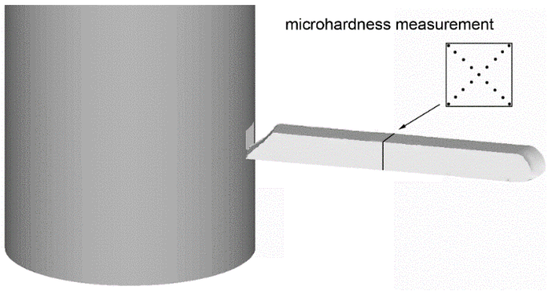
Figure 1. Depiction of locations for microhardness measurements.
Metals 15 00368 g001
Figure 2. Distribution of Hensel–Spittel model residues.
Metals 15 00368 g002
Figure 3. Graphical depiction of a cut through the assembly for ECAP processing.
Metals 15 00368 g003
Figure 4. Axial cutting plane with localization of: sensors (a), superimposed grid (b).
Metals 15 00368 g004
Figure 5. Flow stress curves for Cu-La2O3 composites, as-cast and ECAP-processed.
Metals 15 00368 g005
Figure 6. Flow stress curves of ECAP-processed composite: with no heat treatment (a), and after 250 °C/30 min heat treatment (b).
Metals 15 00368 g006
Figure 7. Vickers microhardness measured along intersecting diagonals across cross-sections of as-cast and ECAP-processed composites.
Metals 15 00368 g007
Figure 8. Microstructure of as-cast Cu-La2O3 composite: OIM image (a); phase map (b).
Metals 15 00368 g008
Figure 9. Microstructure of ECAP-processed Cu-La2O3 composite: OIM image (a); IPF images (b). Detailed views on microstructure: OIM image (c); phase map (d). Close view on substructure: OIM image (e); phase map (f).
Metals 15 00368 g009aMetals 15 00368 g009b
Figure 10. Temperature distribution during ECAP processing: contours (a), time development for individual sensors (b).
Metals 15 00368 g010
Figure 11. Distribution of imposed effective strain during ECAP: contours (a), time development for individual sensors (b).
Metals 15 00368 g011
Figure 12. Predicted distribution of: von Mises stress (a), residual stress (b).
Metals 15 00368 g012
Figure 13. Development of punch load in time during ECAP processing.
Metals 15 00368 g013
Figure 14. Plastic flow during ECAP: superimposed grids (a), vector profiles (b).
Metals 15 00368 g014
Table 1. Material constants for 99.97% pure Cu and Cu-La2O3 composite.
ParameterCu 99.97Cu-La2O3
A411.19318.87
m1−0.00121−0.01241
m20.21554−0.10732
m30.014720.00346
m4−0.00935−0.01617
m500.11678
m70−0.90557
m800.00054
m90−0.11201
Disclaimer/Publisher’s Note: The statements, opinions and data contained in all publications are solely those of the individual author(s) and contributor(s) and not of MDPI and/or the editor(s). MDPI and/or the editor(s) disclaim responsibility for any injury to people or property resulting from any ideas, methods, instructions or products referred to in the content.