Article

Effects of a Welding Wire Containing Er or Sc on the Microstructure, Mechanical Properties, and Corrosion Resistance of the 5xxx Aluminum Alloy MIG Joint

1
School of New Energy Vehicle, Nanning Vocational and Technical University, Nanning 530008, China
2
Key Laboratory of Superlight Materials & Surface Technology, Ministry of Education, Harbin Engineering University, Harbin 150001, China
3
School of New Energy and Mining, Xinjiang University of Technology, Hetian 848000, China
*
Authors to whom correspondence should be addressed.
Metals 2025, 15(3), 287; https://doi.org/10.3390/met15030287
Submission received: 26 December 2024 / Revised: 19 February 2025 / Accepted: 4 March 2025 / Published: 6 March 2025
(This article belongs to the Special Issue Manufacturing Processes of Metallic Materials)

Abstract

The development of MIG (metal inert gas) welding for five-series aluminum alloys primarily involves the improvement and optimization of welding processes. Building upon research findings regarding the enhancement of aluminum alloy properties through the use of scandium (Sc) and erbium (Er), our study incorporates Sc and Er into the welding wire to examine their impact on welding quality. The results show that the introduction of Er and Sc results in grain refinement from 47 µm to 29 µm and 31 µm, respectively. Grain refinement is mainly attributed to the heterogeneous nucleation of submicron-sized, coherent Al3Er and Al3Sc phases with L12 structure. The ultimate tensile strength (UTS), fracture elongation EI [%], and microhardness of joints welded with Er-containing and Sc-containing filler wires exhibit significant enhancements due to the refinement strengthening and dispersion strengthening. Joints welded with the filler wires containing Er and Sc display reduced corrosion current density and higher corrosion potential. The enhanced corrosion resistance comes from the formation of a denser oxide film and the equilibrium in the potential difference between the precipitated phases (Al3Er and Al3Sc) and the matrix. Filler wires containing Er and Sc have almost similar effects on improvements of the MIG welding joints.

1. Introduction

Scandium (Sc) and zirconium (Zr) are commonly added to aluminum–magnesium alloys to enhance their mechanical properties through the formation of core–shell Al3(Sc,Zr) phases, which act as effective strengthening agents [1,2,3]. However, the high cost of scandium has prompted the search for more economical alternatives. Neodymium (Er) has emerged as a promising substitute, forming similar core–shell Al3(Er,Zr) phases that offer comparable benefits, including grain refinement, recrystallization inhibition, and precipitation strengthening [4,5,6,7,8]. The application of aluminum alloys in shipbuilding heavily relies on effective joining techniques. Fusion welding methods, such as metal inert gas (MIG) and tungsten inert gas (TIG) welding, are widely used for joining 5000 series aluminum alloys [9,10]. In particular, MIG welding provides deep penetration, high deposition rates, and enhanced production efficiency, making it suitable for welding thicker plates (thickness ≥ 1.6 mm) [11,12]. The corrosion resistance of 5000 series aluminum alloy welds is a critical factor in their application, particularly in marine environments. The primary failure mechanisms of these alloys are often associated with localized corrosion, such as pitting and intergranular corrosion (IGC), which can be exacerbated by microstructural inhomogeneities introduced during the welding process [13,14]. The presence of intermetallic compounds also strongly influences the electrochemical behavior of the alloys [15,16]. Recent studies have emphasized the importance of controlling the microstructure to enhance the corrosion resistance of 5000 series aluminum alloys. For instance, the addition of scandium has been shown to significantly reduce IGC susceptibility by altering the distribution and morphology of intermetallic phases, hindering recrystallization, and reducing continuous precipitation [17,18]. Furthermore, the use of optimized welding parameters can modify the distribution of grain boundary phases, affecting the intergranular corrosion resistance of different regions and thereby improving the overall corrosion resistance of the weld [16].
The selection of appropriate welding filler materials is crucial for achieving high-quality welds. However, research on welding filler materials for 5000 series aluminum alloys, particularly those containing scandium or neodymium, remains limited. In this study, three types of welding filler wires—Al-Mg-Mn-Zr, Al-Mg-Mn-0.2%Sc-Zr, and Al-Mg-Mn-0.2%Er-Zr—were designed for the MIG welding of cold-rolled Al-Mg-Mn-Er-Zr plates with a thickness of 4 mm. By examining the interactions between microstructural characteristics and corrosion, the effects of adding scandium and neodymium to the welding filler materials on the microstructure, mechanical properties, and corrosion resistance of Al-Mg-Mn-Er-Zr welds were systematically investigated.

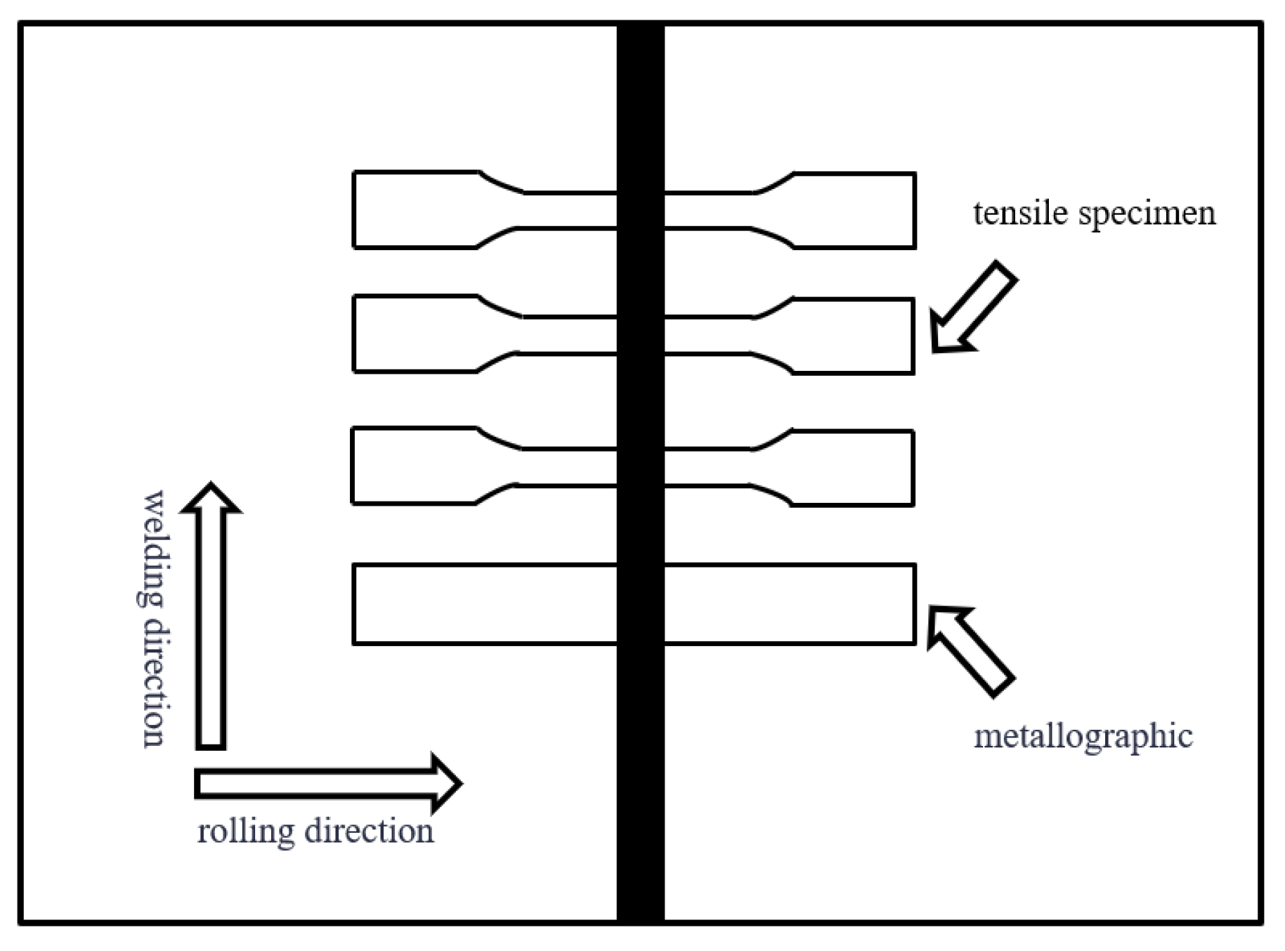
2. Materials and Methods

The base metal and three filler wire materials (Wire-1: Al-Mg-Mn-Zr filler wire, Wire-2: Al-Mg-Mn-Er-Zr filler wire, Wire-3: Al-Mg-Mn-Sc-Zr filler wire) were sourced from Northeast Light Alloy Co., Ltd. (Harbin, China). Their compositions were determined via inductively coupled plasma–atomic emission spectroscopy(ICP-AES), as listed in Table 1. Prior to conducting MIG welding, we cut the sample using wire cutting, polished it with metallographic sandpaper of varying particle sizes, and then polished it with water on a PG-1A polishing machine. Subsequently, the surface of the sample was corroded with Keller’s reagent, the surface was cleaned sequentially with purified water and anhydrous ethanol, and finally, it dried quickly with a hair dryer. During the MIG welding process, pure argon gas was used as shielding gas. MIG welding was executed on the butt of the cold-rolled Al-6Mg-0.8Mn-0.2Er-0.15Zr plates with a thickness of 4mm, with the welding direction perpendicular to the rolling direction, As shown in Figure 1, through welding wire overlay experiments [19], the welding current and welding speed were explored, and the final welding parameters obtained are shown in Table 2.
All the specimens were gained from the central region of the joint and perpendicular to the weld seam. For metallographic observations, the samples were etched for 15 s using Keller’s reagent solution (2.5HNO3:1.5HCl:1HF:95H2O) and were observed using an optical microscope (OM, LEICA DM IRM, Leica Microsystems GmbH, Wwtzlar, Germany). The microstructures and fracture surfaces of the joints were observed using a scanning electron microscope (SEM, Quanta-200, Thermo Fisher Scientific, Hillsboro, OR, USA) and a transmission electron microscope (TEM, JEM-2100 EX, JEOL Ltd., Tokyo, Japan), both equipped with energy-dispersive X-ray spectroscopy (EDS, EDAX Genesis, EDAX Inc., Princeton, NJ, USA).
The mechanical properties of MIG-welded joints were tested using a universal testing machine (WDW 3050, Cangzhou Zhongke Beigong Test Instrument Co., Ltd., Cangzhou, China). Tensile specimens were perpendicular to the weld seam, with the weld axis positioned at the midpoint of the parallel section of the specimen. Tensile testing was conducted at a rate of 0.5 mm/min, and an average value was obtained from five parallel tests. Microhardness measurements were performed using an microhardness tester (HXS-1000Z, Guiyang Milite Instrument Co., Ltd., Guiyang, China), with a load of 0.98 N and a dwell time of 15 s. Measurements were taken at 1 mm intervals from the center of the weld seam towards both sides.
The corrosion resistance of the welded joints was tested using an electrochemical workstation (Im6/Im6ex). For the electrochemical measurements, a saturated calomel electrode, platinum sheet, and the specimens served as the reference electrode, auxiliary electrode, and working electrode, respectively, while a 3.5% NaCl (by mass) solution was utilized as the electrolyte. During the polarization curve test, the open circuit potential was initially determined. Subsequently, the upper and lower limit potentials were set at ±0.3 V relative to the open circuit potential. A scan rate of 0.1 mV/s was employed to generate Tafel curves, from which corrosion current density and corrosion potential were derived through curve fitting. Each sample required 3 separate samples to be tested, and a total of 9 samples were tested.

3. Results and Discussion

3.1. Macroscopic Observation of Weld Seam Formation

Figure 2 illustrates the surface morphology of the weld seams on both the front and back sides of the butt MIG-welded joints. Subject to identical welding process parameters, the quality of the weld seams remains consistent. On the front side, uniform and finely detailed fish-scale patterns are evident, while on the back side, there is ample weld penetration, resulting in the creation of teardrop-shaped weld pools. This morphology shows that it allows single-side welding with double-sided formation, producing welds characterized by density, esthetic appeal, minimal spatter, and narrow weld bead widths. The back side of the weld seam displays complete fusion, devoid of any discernible defects such as weld cracks and incomplete fusion or biting edges. These observations attest to the stability of the welding process and the high-quality formation of the weld seams.

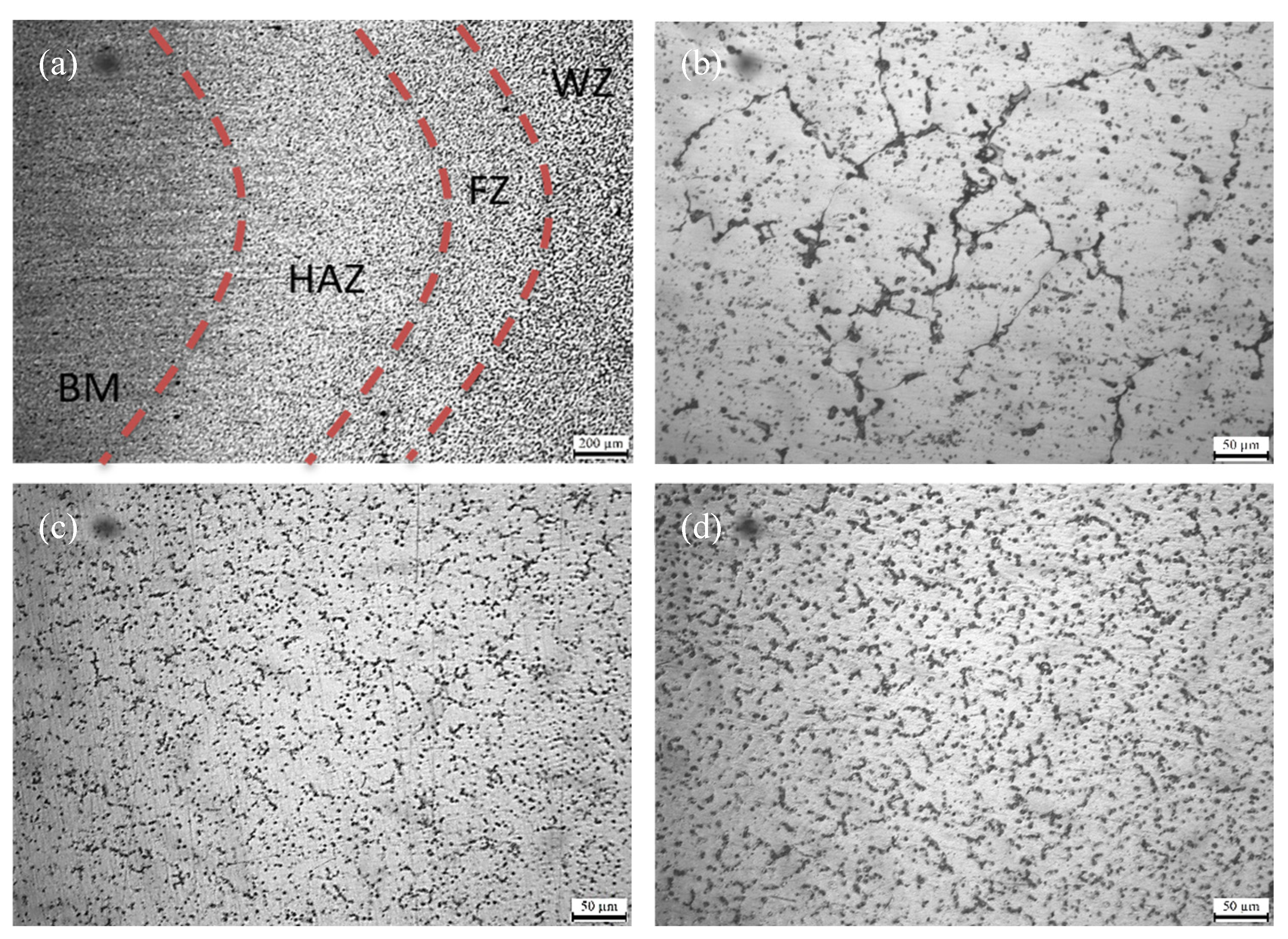
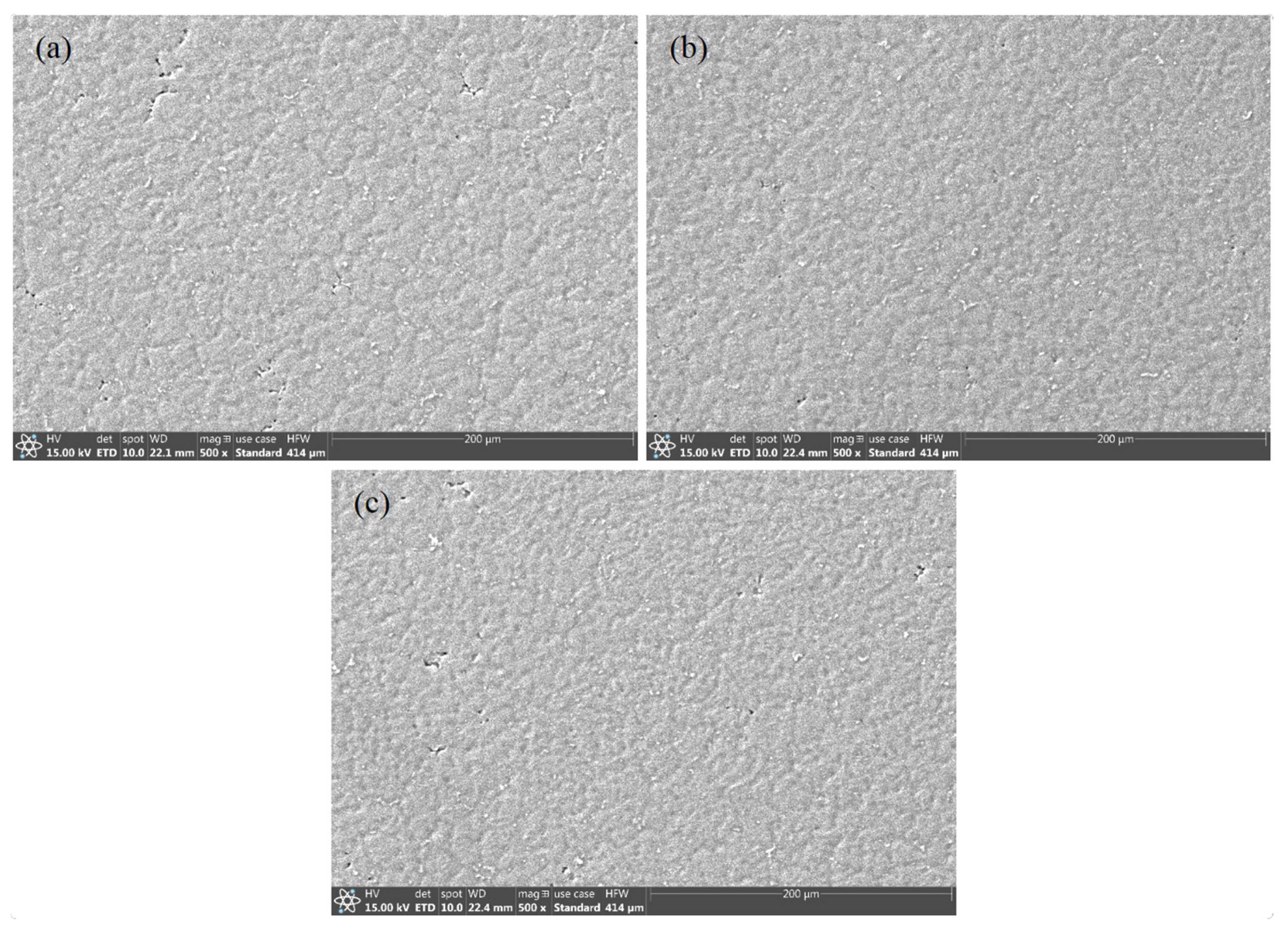
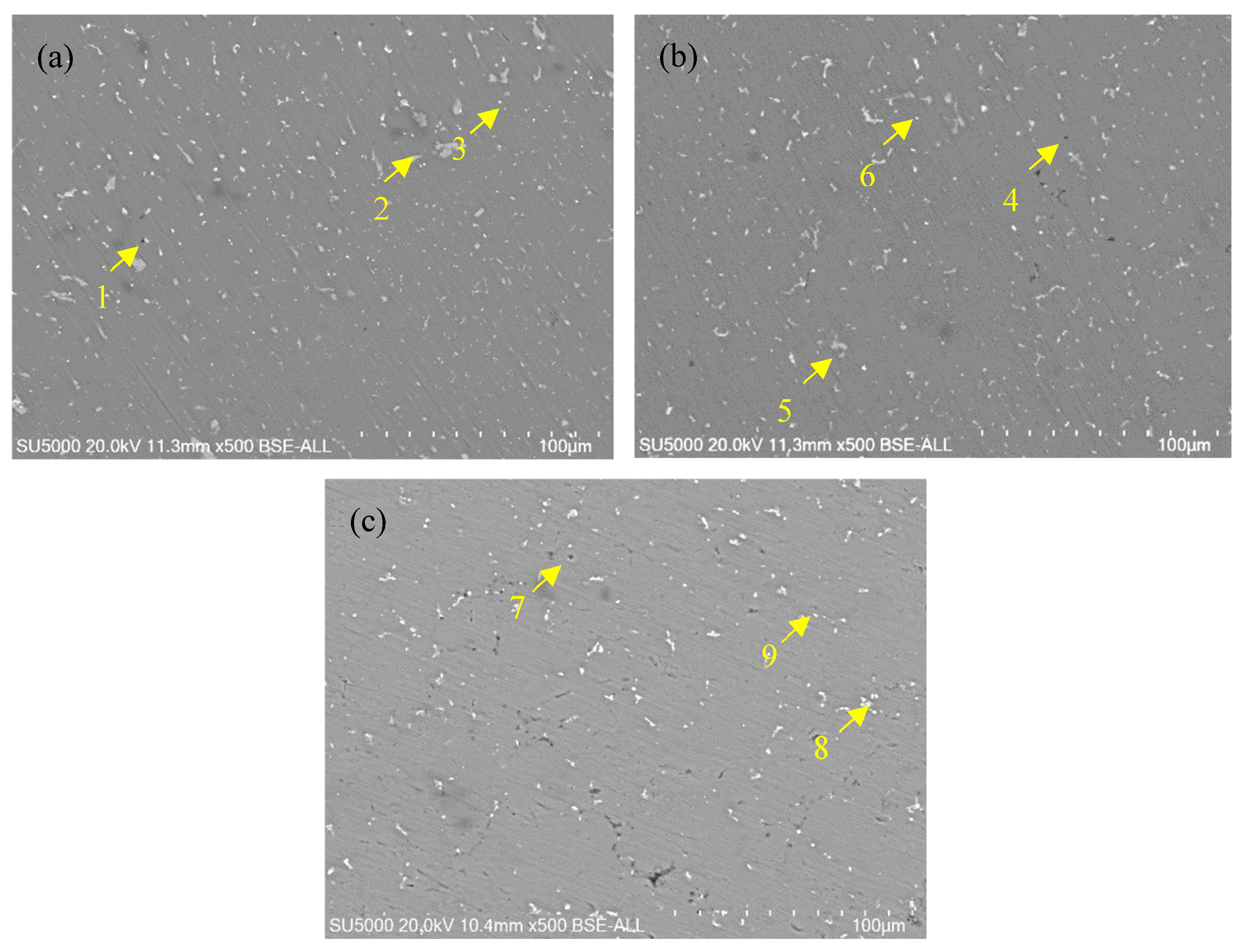
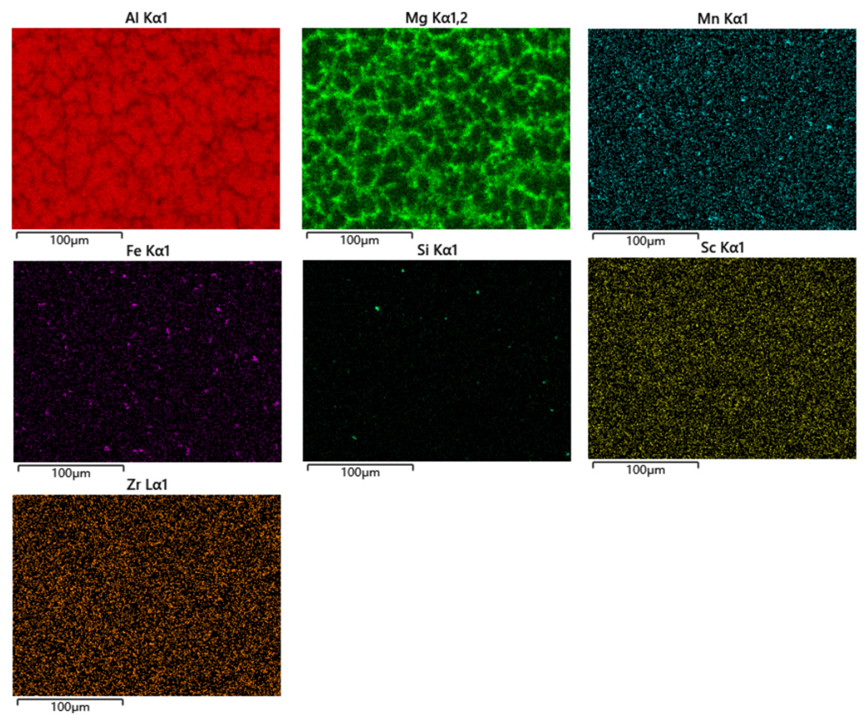
3.2. Microstructure Observation

Figure 3a illustrates the low-magnification microstructure of the Wire-2 joint, which can be primarily divided into four typical regions: the base metal region (BM), the heat-affected zone (HAZ), the fusion zone (FZ), and the welding zone (WZ). In the BM, a fibrous structure resulting from rolling remained. Aluminum alloys containing Er and Zr can form numerous fine Al3(Er,Zr) particles during the welding process. These nanoscale particles effectively suppress recrystallization [20], resulting in the retention of more deformation structures during welding. The HAZ exhibits a microstructure with partial recrystallization due to the influence of the welding heat input, resulting in relatively coarser fibrous structures [21]. During welding, the temperature gradient typically leads to higher temperatures at the center of the weld. A transitional region, known as the fusion zone, is located between the welding zone (WZ) and the heat-affected zone (HAZ). It is characterized by grains with a distinct crystallographic orientation that extends from the welding zone towards the heat-affected zone. These grains form elongated structures with non-uniform sizes. The morphologies of the welding joints for the three types of welding wires are similar; therefore, only the low-magnification microstructure of the Wire-2 joint is presented here.
Figure 3b–d depict the metallographic microstructures of the welding zones in the joints of Wire-1, Wire-2, and Wire-3, respectively. They all exhibit typical cast microstructures characterized by equiaxed grains. However, there are significant variations in grain size. All the samples were treated by electrolytic polishing and then observed by SEM, as shown in Figure 4. According to the calculations using IPP software (Image-Pro Plus 8.0), the Wire-1 joint exhibits the largest grain size, approximately 47 µm. In contrast, the joints with Wire-2 and Wire-3 have comparable grain sizes, approximately 29 µm and 31 µm, respectively. This discrepancy in grain size can be attributed to the incorporation of Er and Sc in Wire-2 and Wire-3. The presence of these elements in the welding wires leads to the formation of Er-containing and Sc-containing phases within the weld zones, which promote nucleation in the joints [22].
The presence of fine equiaxed grains, particularly within the welding zone (WZ), is predominantly attributed to the elevated cooling rates during welding. The rapid cooling process, facilitated by the high thermal conductivity of the base metal (BM) and the plentiful and non-uniform nucleation sites offered by the weld pool’s edges, foster grain refinement. These refined grains hinder the growth of dendrites, accounting for the absence of dendritic structures in the WZ.
Figure 5 depict SEM images (back-scattered electron image) of the weld zone for the joints. The EDS results corresponding to points 1 to 9 in Figure 5 are presented in Table 3. Bright regions in Figure 5 indicate an enrichment of higher atomic weight elements, while dark regions represent the α-Al matrix. The results reveal that the black, granular second phase corresponds to the Mg-Si phase, the light gray, blocky second phase corresponds to the Al-Mn-Fe phase, and the bright white granular and lamellar second phases correspond to the Al-Mg phase, which precipitates along grain boundaries. Figure 6 shows the energy spectrum of the SEM image in Figure 5c. From this figure, the enrichment of various elements at the joint of Wire-3 can be observed, which is consistent with the inferred elemental composition in Table 3. Since the compositions of the three welding joints are similar, only the EDS image of Wire-3 is presented.
In the weld zones of the joints, the geometric shapes and distribution of these second phases are largely consistent. Since the three filler wires have almost the same composition and the same welding parameters are used, the phase compositions in the weld zone are identical. Due to the smaller size of the precipitates formed by Er and Sc elements, they could not be observed with SEM microscopy and were further examined in the subsequent TEM analysis.
The existence of Sc and Er triggers eutectic reactions during the solidification of the welding zone, resulting in the formation of submicron-sized Al3Sc and Al3Er phases. These phases play a pivotal role in facilitating the precipitation of solute atoms, thereby providing heterogeneous nucleation sites for subsequent solidification processes. This mechanism effectively refines the dendritic structure of the weld while simultaneously inhibiting excessive grain growth, thus achieving fine-grain strengthening in the weld zone.
We utilized an electric discharge wire-cutting machine to slice the test sample into thin sections measuring 5 mm × 5 mm × 1 mm. Subsequently, we polished these thin sections with 320 and 2000-grit sandpaper until they were less than 35 μm thick, ensuring uniformity in thickness. We employed the Gatan 695 C ion-thinning instrument to further refine the transmission sample. Prior to thinning, we used a punch to create and cut out a circular piece with a 3 mm diameter. The ion thinning process involves initially thinning the sample at a large angle (8°) and high voltage (3 eV) for 1–2 h. Once a hole was formed in the sample, we decreased the angle to 6° and the voltage to 3.5 eV, continuing for approximately 0.5 h. Finally, we reduced the angle to 3° while maintaining the voltage at 3.5 eV and thinned this for an additional 10–20 min to achieve a transparent sample. Microstructural changes within the weld zones of joints between Wire-2 and Wire-3, stemming from the introduction of Er and Sc, were meticulously examined via transmission electron microscopy (TEM), as shown in Figure 7 and Figure 8. Although Al3(Sc,Zr) and Al3(Er,Zr) particles inherently possess high-temperature stability and relatively elevated melting points (approximately 1320 °C), it is noteworthy that these particles tend to become coarser during the welding process, primarily due to the temperatures reaching up to 1200 °C at the core of the weld [23]. Consequently, the Al3(Sc,Zr) and Al3(Er,Zr) particles undergo a transition from the nanoscale to the submicron scale. Detailed observations from Figure 7 and Figure 8 reveal that the size of the Al3Sc and Al3Er phases within the weld zones of joints are approximately 200 nm, with no presence of other nanoscale particles [24]. Conventionally, within the context of MIG welding, alloying elements tend to dissolve into the aluminum matrix, and the rapid cooling rates prevalent in this process yield only limited solute precipitation from the matrix, subsequently forming new phases. TEM diffraction patterns unambiguously confirm that the precipitated phases indeed correspond to Al3Sc and Al3Er, showcasing a characteristic L12 structural arrangement. Due to the almost identical lattice structure of Al3Sc, Al3Er, and α-Al, the discrepancy between the lattice parameters is about 1.5% [25].
In summary, natural air cooling fosters the formation of fine equiaxed grains within the weld zone, and the introduction of Er and Sc elements in the form of submicron Al3Sc and Al3Er phases further refines the grains [26]. Furthermore, it is noteworthy that the geometric characteristics of grains within the fusion zone (FZ) remain significantly influenced by the welding thermal cycles.

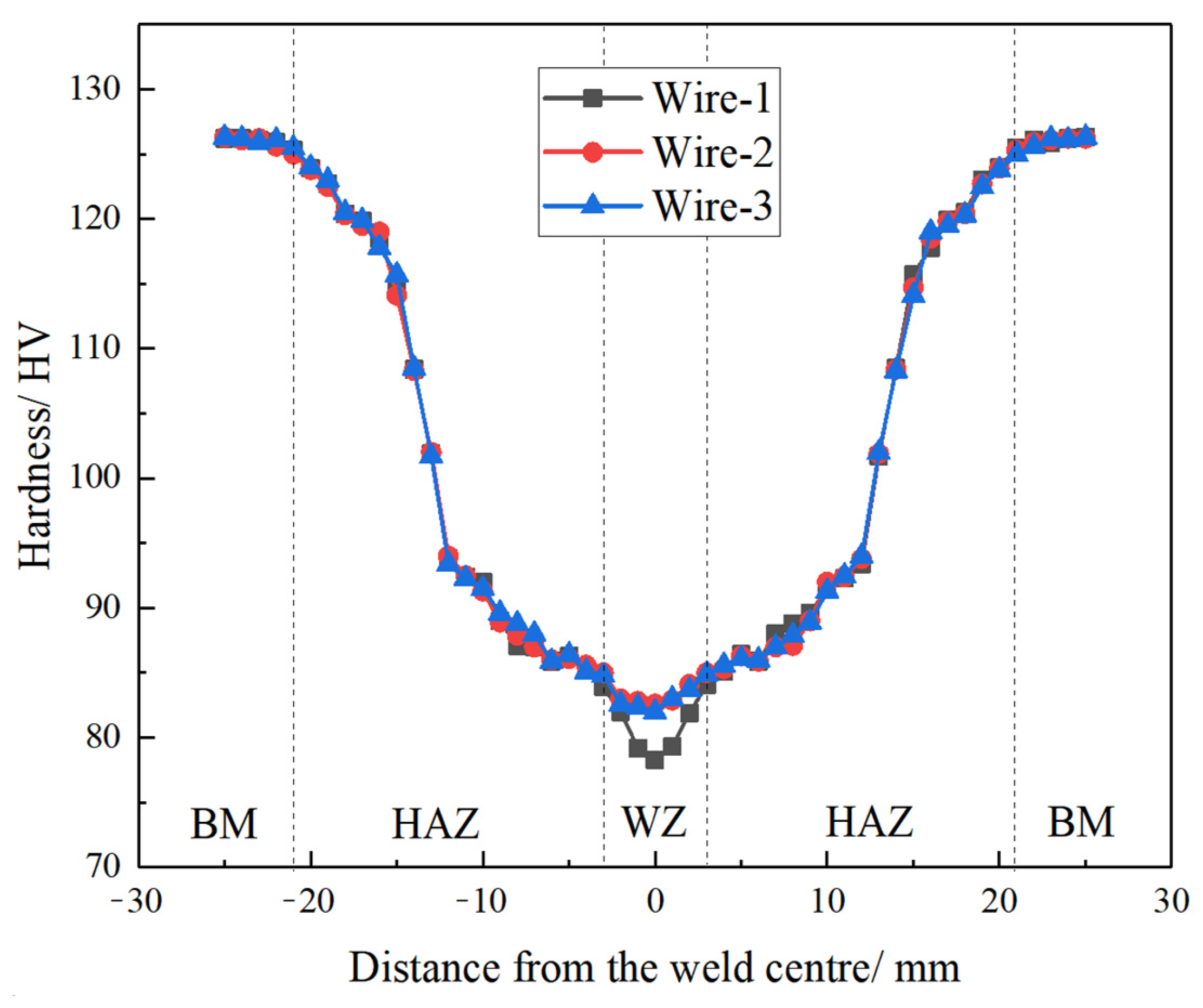
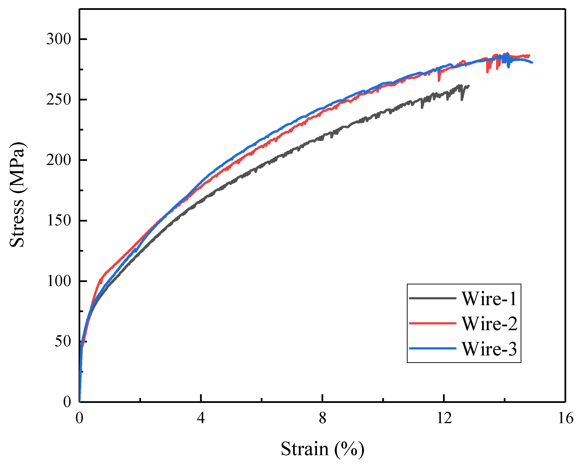
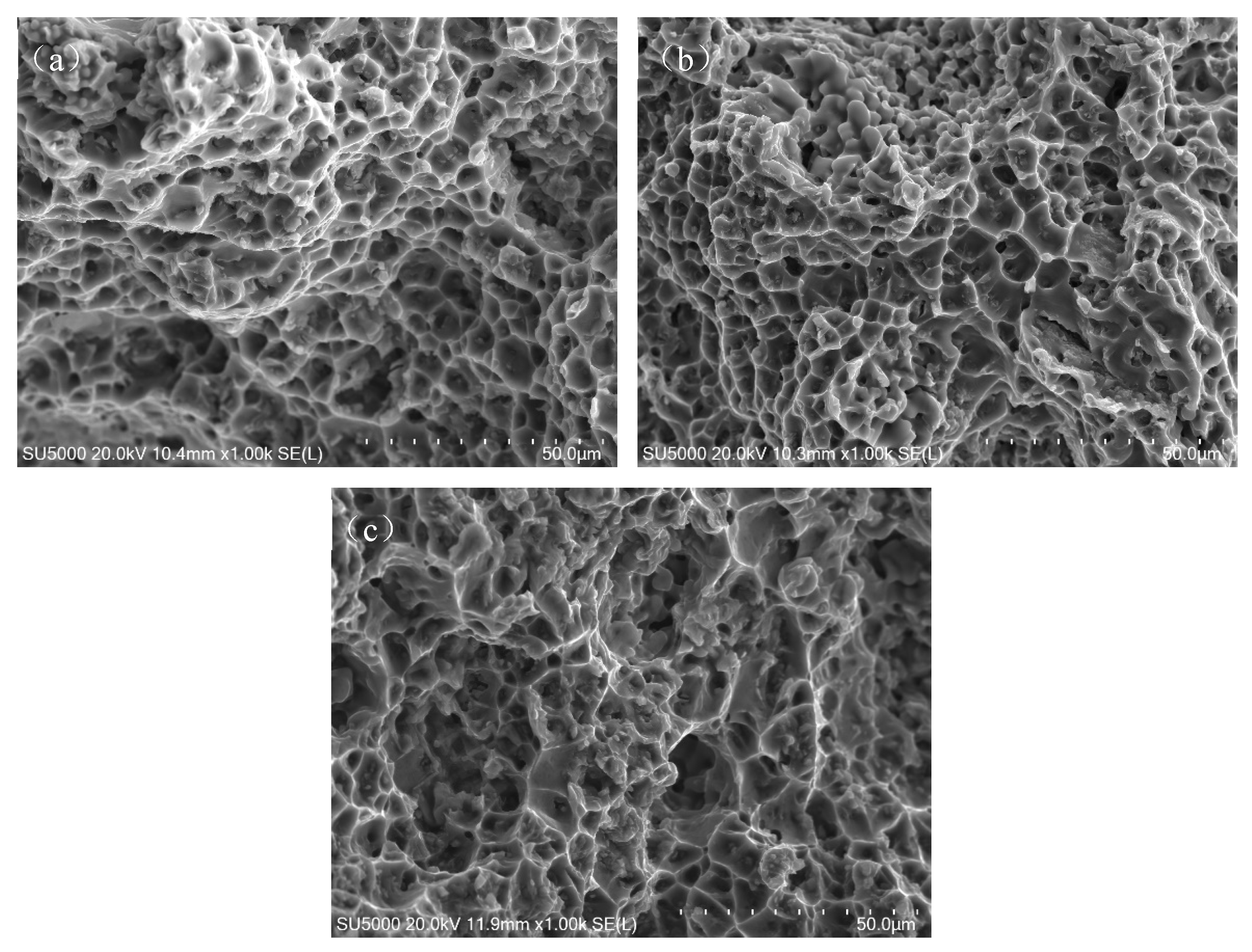
3.3. Mechanical Properties

During MIG welding, the three types of welding wires are melted by the electrode and solidified on the adjacent workpiece, resulting in the formation of the weld joint [19]. Figure 9 illustrates the microhardness distribution of MIG-welded joints. The trends in hardness variation were generally consistent across the three groups of joints and exhibited symmetry along the center of the weld. It is apparent that MIG-welded joints comprise the welding zone (WZ), heat-affected zone (HAZ), and base metal (BM). The BM typically exhibits a coarse-grained structure due to the rolling process. The presence of fine Al3(Er,Zr) precipitates in the BM helps to pin dislocations and sub-grain boundaries, resulting in a high microhardness (approximately 126 HV) and good mechanical strength. The HAZ experiences partial recrystallization due to thermal cycling during welding, leading to a gradient microstructure with coarser grains near the BM and finer grains near the WZ. The fibrous structure in the HAZ is retained due to the suppression of recrystallization by Al3(Er,Zr) precipitates. The HAZ exhibits a gradual transition in microhardness, with values lower than the BM but higher than the WZ.
In the weld zone, the average microhardness of joints with Wire-2 and Wire-3 is quite similar and significantly higher than that with Wire-1, measuring approximately 82 HV. In contrast, the average microhardness of Wire-1 joints in the weld zone is approximately 78 HV. Within the weld zone of Wire-2 and Wire-3 joints, fine equiaxed grain structures dominate. Furthermore, the precipitated Al3Er and Al3Sc phases provide numerous sites for heterogeneous nucleation, refining the grains during the solidification of the welding melt. Consequently, under the same MIG welding parameters, the weld zone hardness of the joint with Wire-1 is lower than that with Wire-2 and Wire-3. As the welding heat input remains consistent under the same welding parameters, the heat-affected zone (HAZ) width is nearly identical among the three welded joints, resulting in similar hardness values in this region.
In the center of the weld zone, the absence of precipitated Al3(Er,Zr)/Al3(Sc,Zr) particles, along with the strengthening effects of substructures and deformation, collectively contribute to the lowest microhardness values observed in this region. As depicted in Figure 3, it is evident that there is a gradual transition from fine equiaxed grains to fibrous structures. Consequently, a recovery in microhardness can be observed, which is attributed to fine grain strengthening and work-hardened states. The high-melting-point Al3(Er,Zr)/Al3(Sc,Zr) particles in the base metal do not undergo aggregation or coarsening even when exposed to the elevated temperature of MIG welding. They persist in pinning dislocations and sub-grain boundaries. Consequently, the heat-affected zone is primarily composed of fibrous structures, although some small, recrystallized grains are observed near the fusion line.
The tensile stress–strain curves for joints are presented in Figure 10. To facilitate a more direct comparison of the tensile properties of joints, specific values for ultimate tensile strength and fracture elongation are listed in Table 4.
The fracture locations of the tensile specimens are all within the weld zone. In the base metal, coherently distributed Al3(Er,Zr) particles are uniformly dispersed within the matrix, resulting in fine microstructures and significant strengthening effects. In contrast, in the weld zone, work-hardening effects are absent. Additionally, most of the major alloying elements are dissolved within the supersaturated solid solution of Al, with only small quantities of precipitated Al3Er and Al3Sc phases in the joints with Wire-2 and Wire-3. Consequently, considering the strengthening effects of Al3(Er,Zr) particles through deformation and precipitation, the hardness of all joints is lower than that of the base metal (BM). The tensile properties of the joints are closely related to their grain size. The well-known Hall–Petch equation describes the contribution of grain size to yield strength, with a smaller grain size resulting in higher yield strength. The fine-grained structure of the WZ enhances the mechanical properties through the Hall–Petch effect, where smaller grain sizes lead to higher yield strength. The WZ of Wire-2 and Wire-3 joints exhibits higher microhardness (approximately 82 HV) and superior tensile strength (287 ± 6 MPa and 286 ± 6 MPa, respectively) compared to Wire-1 joints (78 HV and 261 ± 6 MPa). The fine equiaxed grains also contribute to improved ductility, as evidenced by the higher fracture elongation (14.8 ± 0.3% and 14.9 ± 0.3% for Wire-2 and Wire-3, respectively) [27,28,29]. These results indicate that the mechanical performance of joints with Wire-2 and Wire-3 is quite similar and superior to that of joints with Wire-1.
Figure 11 provides high-magnification micrographs of the fracture surfaces of tensile specimens from the joints. The fracture surfaces of all joints are predominantly composed of numerous dimples without prominent cleavage facets or quasi-cleavage features. This behavior is indicative of a typical ductile fracture, highlighting the good plasticity of the joints, with fracture elongations exceeding 10%.

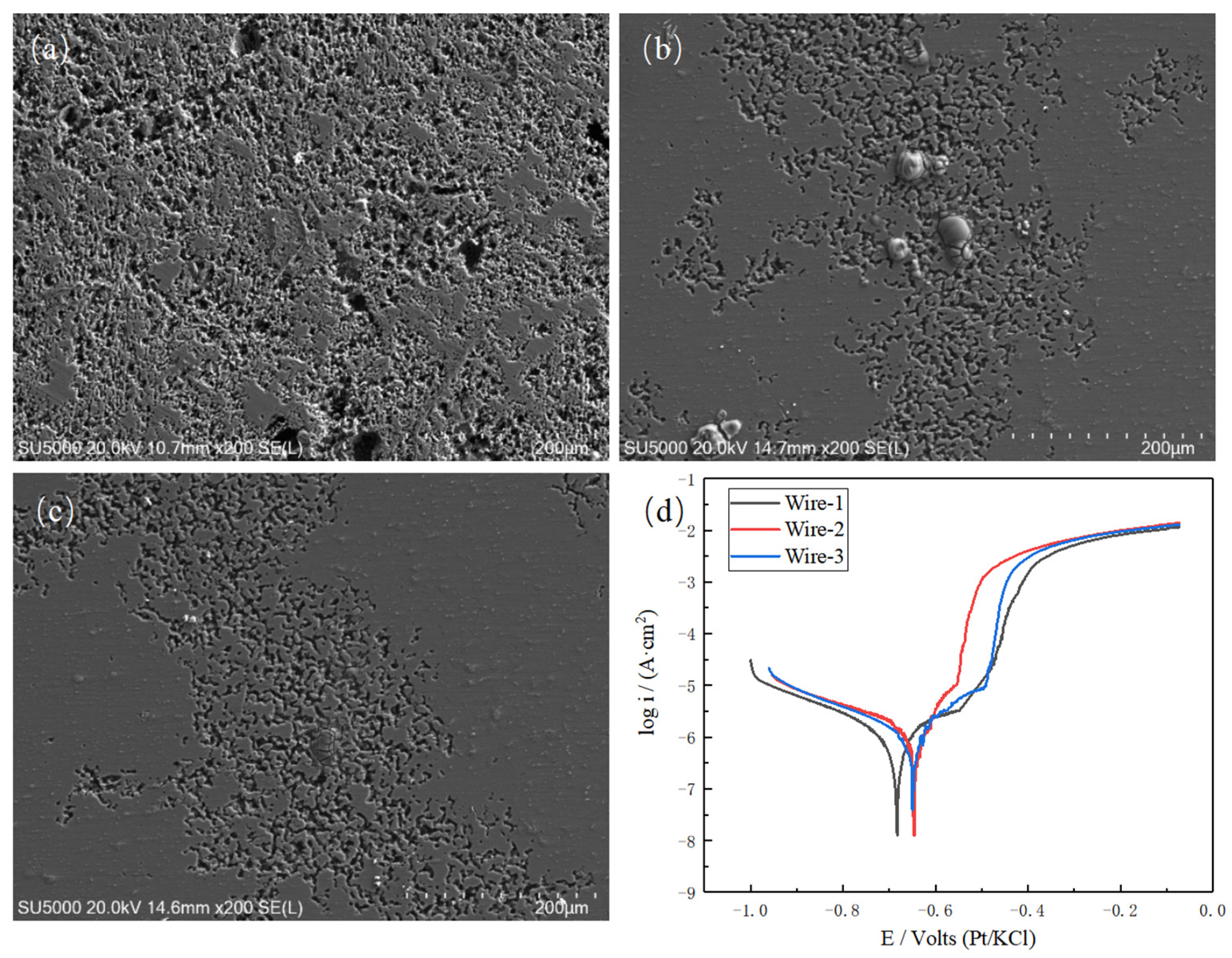
3.4. Corrosion Resistance

The corrosion resistance of aluminum alloys primarily relies on the presence of a passive oxide film on the surface and its capacity for self-repair when it is disrupted. To investigate the influence of the weld zone on the corrosion resistance of joints, the corrosion morphology of the samples in a 3.5% NaCl (by mass) solution and their electrochemical polarization curves were obtained, as illustrated in Figure 12. Employing electrochemical analysis software (CHI760E Electrochemical Testing Software), the self-corrosion potential and corrosion current density of the three welded joints were determined and are presented in Table 5. It is noteworthy that the corrosion current density for joints welded with Wire-1 is 9.266 × 10⁻⁷ A/cm2, accompanied by a corrosion potential of −0.683 V. In contrast, the joints welded with Wire-2 and Wire-3 display corrosion current densities of 8.642 × 10⁻⁷ A/cm2 and 8.775 × 10⁻⁷ A/cm2, coupled with the corrosion potentials of −0.646 V and −0.650 V, respectively. It can be seen from the corrosion morphology that the corrosion area and corrosion depth of the welded joints after adding Er or Sc elements are greatly reduced.
Considering that Wire-2 and Wire-3 incorporate Er and Sc elements, the corrosion current density diminishes while the corrosion potential rises. In accordance with the connection between potential and equilibrium constants, an upward shift in the corrosion potential, specifically a reduction in its absolute value, correlates with a decrease in the equilibrium constant of the corrosion reaction. Consequently, corrosion reactions become less favorable. The corrosion current density is associated with the corrosion rate as follows [30]:
C R   ( m m / y e a r ) = 3.27 M n ρ · i c o r r × 1 0 3
The formula demonstrates a general relationship between the metal corrosion rate and corrosion current density (μA/cm2). In the equation, M represents the atomic weight of the metal atoms (g/mol), n denotes the valency, i represents the current density, and ρ signifies the density of the alloy (g/cm3). For the aluminum matrix, the numerical value of A/nρ is 3.33 cm3/mol. Substituting this value into the above equation reveals that the corrosion rate of Wire-1, Wire-2, and Wire-3 is 1.009 × 10⁻⁸, 9.411 × 10⁻⁹, and 9.555 × 10⁻⁹ mm/year respectively. The addition of rare earth elements Er and Sc significantly reduces the corrosion rate of the welded joint.
The principal reason for the corrosion resistance of aluminum alloy surfaces is the presence of a protective Al2O3 film. The incorporation of Er and Sc leads to the formation of composite Er-Al and Sc-Al oxide films within the interstices of Al2O3 [31,32]. The positions occupied by Er and Sc enhance the binding energy for Al-O, resulting in a denser surface oxide film with greater stability, effectively suppressing cathodic reactions. Additionally, the addition of Er and Sc significantly refines the grain size in the weld zone, with the reduction in grain size contributing to a decrease in pinhole density on the oxide film surface. Accordingly, the addition of Er and Sc reduces the corrosion current density and raises the self-corrosion potential in the weld zone. Rare earth elements affect the properties of the oxide film on the surface of aluminum alloy, making the oxide film denser and preventing the dissolution of aluminum ions, so that the anodic dissolution reaction becomes a rate-controlling reaction.
Inclusions, such as oxides and intermetallic phases (e.g., Al6(Mn,Fe)), act as preferential sites for corrosion initiation due to their higher electrochemical activity compared to the α-Al matrix. These inclusions can lead to localized pitting corrosion, particularly in chloride-containing environments. To mitigate this issue, the addition of Er and Sc in the filler wires (Wire-2 and Wire-3) promotes the formation of Al3Er and Al3Sc phases. These phases act as heterogeneous nucleation sites, refining the grain size and reducing the grain boundary area. This refinement lowers the diffusion rate of corrosive media along the grain boundaries, thereby enhancing the intergranular corrosion resistance of the alloy. Additionally, the presence of Sc and Er further stabilizes the microstructure, contributing to improved overall corrosion resistance. [17,18,33].

4. Conclusions

In this study, three different filler wires were employed for the MIG welding of 4 mm thick Al-Mg-Mn-Er-Zr cold-rolled plates, investigating the influence of adding 0.2% Er and 0.2% Sc to the filler wires on the microstructure, mechanical properties, and corrosion performance of the welded joints. The main conclusions are as follows:
(1) All the joints exhibit excellent external appearance without defects. The additions of Er and Sc refine the grains in the WZs from 47 µm to 29 µm and 31 µm, respectively. This refinement is primarily attributed to the presence of submicron-sized Al3Er and Al3Sc phases.
(2) The three weld joints possess ultimate tensile strengths of 261 ± 6 MPa, 287 ± 6 MPa, and 286 ± 6 MPa and fracture elongations of 12.8 ± 0.3%, 14.8 ± 0.3%, and 14.9 ± 0.3%, respectively. This improvement, due to the additions of Er and Sc, is mainly attributed to the combined effects of refinement strengthening and dispersion strengthening.
(3) The corrosion resistance of Al-Mg-Mn-Er-Zr alloy-welded joints is significantly influenced by grain size, weld morphology, and the presence of inclusions. In the weld zone (WZ), the fine-grained structure, achieved through the addition of Er and Sc, enhances corrosion resistance by stabilizing the passive oxide film and reducing the susceptibility to intergranular corrosion.
(4) With the addition of 0.2%, wire containing Er can effectively replace wires containing Sc, and has the advantage of low cost.

Author Contributions

Conceptualization, C.Z. and X.Y.; Methodology, C.Z. and X.Y.; Formal analysis, C.Z., X.Y. and Z.M.; Resources, L.H.; Data curation, C.Z. and Z.M.; Writing—original draft, C.Z. and X.Y.; Writing—review and editing, R.W. and L.H.; Visualization, C.Z.; Supervision, R.W. and X.Y.; Project administration, R.W. All authors have read and agreed to the published version of the manuscript.

Funding

This paper was supported by the National Natural Science Foundation of China (52261135538), Fundamental Research Funds for the Central Universities (3072024XX1009), and the Russian Science Foundation (23-49-00098).

Data Availability Statement

The original contributions presented in this study are included in the article. Further inquiries can be directed to the corresponding authors.

Conflicts of Interest

The authors declare no conflicts of interest.

References

  1. Yin, Z.; Pan, Q.; Zhang, Y.; Jiang, F. Effect of minor Sc and Zr on the microstructure and mechanical properties of Al–Mg based alloys. Mater. Sci. Eng. A 2000, 280, 151–155. [Google Scholar] [CrossRef]
  2. Wang, Y.; Zhang, S.; Wu, R.; Turakhodjaev, N.; Hou, L.; Zhang, J.; Betsofen, S. Coarsening kinetics and strengthening mechanisms of core-shell nanoscale precipitates in Al-Li-Yb-Er-Sc-Zr alloy. J. Mater. Sci. Technol. 2021, 61, 197–203. [Google Scholar] [CrossRef]
  3. Wang, Y.; Zhang, Z.; Wu, R.; Sun, J.; Jiao, Y.; Hou, L.; Zhang, J.; Li, X.; Zhang, M. Ambient-temperature mechanical properties of isochronally aged 1420-Sc-Zr aluminum alloy. Mater. Sci. Eng. A 2019, 745, 411–419. [Google Scholar] [CrossRef]
  4. Wang, M.; Wei, W.; Shi, W.; Zhou, X.; Wen, S.; Wu, X.; Gao, K.; Rong, L.; Qi, P.; Huang, H.; et al. Synergistic effect of Al3(Er, Zr) precipitation and hot extrusion on the microstructural evolution of a novel Al–Mg–Si–Er–Zr alloy. J. Mater. Res. Technol. 2023, 22, 947–957. [Google Scholar] [CrossRef]
  5. Kotov, A.D.; Mochugovskiy, A.G.; Mosleh, A.O.; Kishchik, A.A.; Rofman, O.V.; Mikhaylovskaya, A.V. Microstructure, superplasticity, and mechanical properties of Al–Mg–Er–Zr alloys. Mater. Char. 2022, 186, 111825. [Google Scholar] [CrossRef]
  6. Nie, Z.R.; Jin, T.; Fu, J.; Xu, G.; Yang, J.; Zhou, J.X.; Zuo, T.Y. Research on rare earth in aluminum. Mater. Sci. Forum 2002, 396, 1731. [Google Scholar] [CrossRef]
  7. Xue, D.; Wei, W.; Shi, W.; Guo, Y.W.; Wen, S.P.; Wu, X.L.; Huang, H.; Nie, Z.R. Effect of cold rolling on mechanical and corrosion properties of stabilized A-Mg-Mn-Er-Zr alloy. J. Mater. Res. Technol. 2021, 15, 6329–6339. [Google Scholar] [CrossRef]
  8. Fu, L.; Li, Y.; Jiang, F.; Huang, J.; Xu, G.; Yin, Z. On the role of Sc or Er micro-alloying in the microstructure evolution of Al-Mg alloy sheets during annealing. Mater. Char. 2019, 157, 109918. [Google Scholar] [CrossRef]
  9. Liu, Y.; Wang, W.; Xie, J.; Sun, S.; Wang, L.; Qian, Y.; Meng, Y.; Wei, Y. Microstructure and mechanical properties of aluminum 5083 weldments by gas tungsten arc and gas metal arc welding. Mater. Sci. Eng. A 2012, 549, 7–13. [Google Scholar] [CrossRef]
  10. Gungor, B.; Kaluc, E.; Taban, E. Mechanical and microstructural properties of robotic cold metal transfer (CMT) welded 5083-H111 and 6082-T651 aluminum alloys. Mater. Des. 2014, 54, 207–211. [Google Scholar] [CrossRef]
  11. Madavi, K.R.; Jogi, B.F.; Lohar, G.S. Metal inert gas (MIG) welding process: A study of effect of welding parameters. Mater. Today: Proc. 2022, 51, 690–698. [Google Scholar] [CrossRef]
  12. Sharma, A.; Verma, A.; Vashisth, D.; Khanna, P. Prediction of bead geometry parameters in MIG welded aluminium alloy 8011 plates. Mater. Today Proc. 2022, 62, 2787–2793. [Google Scholar] [CrossRef]
  13. Sareekumtorn, P.; Chaideesungnoen, S.; Muangjunburee, P.; Oo, H.Z. The electrochemical corrosion performance of aluminum alloys grade 6082-T6 weld repair. Mater. Res. Express 2024, 11, 086512. [Google Scholar] [CrossRef]
  14. Zhao, H.; Li, M.; Wang, X.; Shi, Y.; Chang, Y.; Zhang, G.; Cai, B. Intergranular corrosion effect on fatigue behavior of dissimilar 6005A-5083 aluminum alloys weld joints. Mater. Corros. 2022, 73, 1505–1518. [Google Scholar] [CrossRef]
  15. Rosalbino, F.; Angelini, E.M.M.A.; De Negri, S.; Saccone, A.; Delfino, S. Influence of the rare earth content on the electrochemical behaviour of Al–Mg–Er alloys. Intermetallics 2003, 11, 435–441. [Google Scholar] [CrossRef]
  16. Yang, Z.; Ji, P.; Wu, R.; Wang, Y.; Turakhodjaev, N.; Kudratkhon, B. Microstructure, mechanical properties and corrosion resistance of friction stir welded joint of Al–Mg–Mn–Zr–Er alloy. Int. J. Mater. Res. 2022, 114, 65–76. [Google Scholar] [CrossRef]
  17. Algendy, A.Y.; Rometsch, P.; Chen, X.G. Mechanical and corrosion performances of Al-Mg-Mn 5083 rolled alloys microalloyed with Sc and Zr in different thermomechanical processing conditions. J. Mater. Sci. 2024, 59, 14692–14715. [Google Scholar] [CrossRef]
  18. Shi, J.; Hu, Q.; Zhao, X.; Liu, J.; Zhou, J.; Xu, W.; Chen, Y. Densification, Microstructure and Anisotropic Corrosion Behavior of Al-Mg-Mn-Sc-Er-Zr Alloy Processed by Selective Laser Melting. Coatings 2023, 13, 337. [Google Scholar] [CrossRef]
  19. Shih, J.S.; Tzeng, Y.F.; Yang, J.B. Principal component analysis for multiple quality characteristics optimization of metal inert gas welding aluminum foam plate. Mater. Des. 2011, 32, 1253–1261. [Google Scholar] [CrossRef]
  20. Deng, Y.; Xu, G.; Yin, Z.; Lei, X.; Huang, J. Effects of Sc and Zr microalloying additions on the recrystallization texture and mechanism of Al–Zn–Mg alloys. J. Alloys Compd. 2013, 580, 412–426. [Google Scholar] [CrossRef]
  21. Geng, S.; Jiang, P.; Shao, X.; Guo, L.; Gao, X. Heat transfer and fluid flow and their effects on the solidification microstructure in full-penetration laser welding of aluminum sheet. J. Mater. Sci. Technol. 2020, 46, 50–63. [Google Scholar] [CrossRef]
  22. Han, C.; Jiang, P.; Geng, S.; Mi, G.; Wang, C.; Li, Y. Nucleation mechanisms of equiaxed grains in the fusion zone of aluminum-lithium alloys by laser welding. J. Mater. Res. Technol. 2021, 14, 2219–2232. [Google Scholar] [CrossRef]
  23. Samiuddin, M.; Li, J.L.; Taimoor, M.; Siddiqui, M.N.; Siddiqui, S.U.; Xiong, J.T. Investigation on the process parameters of TIG-welded aluminum alloy through mechanical and microstructural characterization. Def. Technol. 2020, 17, 1234–1248. [Google Scholar] [CrossRef]
  24. Tong, X.; Wu, G.; Zhang, L.; Wang, Y.; Liu, W.; Ding, W. Microstructure and mechanical properties of repair welds of low-pressure sand-cast Mg-Y-RE-Zr alloy by tungsten inert gas welding. J. Magnesium Alloys 2022, 10, 180–194. [Google Scholar] [CrossRef]
  25. Zhang, X.; Wang, H.; Yan, B.; Zou, C.; Wei, Z. The effect of grain refinement and precipitation strengthening induced by Sc or Er alloying on the mechanical properties of cast Al-Li-Cu-Mg alloys at elevated temperatures. Mater. Sci. Eng. A 2021, 822, 141641. [Google Scholar] [CrossRef]
  26. Xiang, H.; Liu, P.L.; Huang, Y.; Liu, Z.H.; Deng, S.X.; Liu, T.L.; Li, J.F.; Liu, D.Y. Effects of the filler wire composition on the structures and mechanical performance of 2195 AlLi alloy TIG joints. Mater. Charact. 2023, 198, 112748. [Google Scholar] [CrossRef]
  27. Zhang, D.K.; Wu, A.; Zhao, Y.; Shan, J.; Wan, Z.; Wang, G.; Song, J.; Zhang, Z.; Liu, X. Microstructural evolution and its effect on mechanical properties in different regions of 2219-C10S aluminum alloy TIG-welded joint. Trans. Nonferrous Metals Soc. China 2020, 30, 2625–2638. [Google Scholar] [CrossRef]
  28. Jia, Q.; Rometsch, P.; Kürnsteiner, P.; Chao, Q.; Huang, A.; Weyland, M.; Bourgeois, L.; Wu, X. Selective laser melting of a high strength Al-Mn-Sc alloy:alloy design and strengthening mechanisms. Acta Mater. 2019, 171, 108–118. [Google Scholar] [CrossRef]
  29. Yang, Z.; Liao, Y.; Wu, R.; Sun, D.; Liu, M.; Wang, Y. Effect of Single-Pass Large-Strain Rolling on Microstructure and Mechanical Properties of Al-3Li-1Cu-0.2Er-0.1Zr Alloy. J. Mater. Eng. Perform. 2022, 31, 3287–3298. [Google Scholar] [CrossRef]
  30. ASTM G102-89; Standard Practice for Calculation of Corrosion Rates from Electrochemical Measurements. ASTM International: West Conshohocken, PA, USA, 2015.
  31. Ahmad, Z.; UI-Hamid, A.; Abdul-Aleem, B.J. The corrosion behavior of scandium alloyed Al 5052 in neutral sodium chloride solution. Corros. Sci. 2001, 43, 1227–1243. [Google Scholar] [CrossRef]
  32. Chen, H.; Yu, T.; Qi, Z.; Wu, R.; Wang, G.; Lv, X.; Cong, F.; Hou, L.; Zhang, J.; Zhang, M. Effect of Minor Er on the Microstructure and Properties of Al-6.0Mg-0.4Mn-0.1Cr-0.1Zr Alloys. J. Mater. Eng. Perform. 2018, 27, 5709–5717. [Google Scholar] [CrossRef]
  33. Xing, Q.; Wu, X.; Zang, J.; Meng, L.; Zhang, X. Effect of Er on Microstructure and Corrosion Behavior of Al–Zn–Mg–Cu–Sc–Zr Aluminum Alloys. Materials 2022, 15, 1040. [Google Scholar] [CrossRef] [PubMed]
Figure 1. Welding wire performance test diagram.
Metals 15 00287 g001
Figure 2. Surface morphology of welded joints: (a) Wire-1; (b) Wire-2; and (c) Wire-3.
Metals 15 00287 g002
Figure 3. Optical microstructure of cross-section of welded joint: (a) appearance of welded joint of Wire-2; (b) WZ of Wire-1; (c) WZ of Wire-2; and (d) WZ of Wire-3.
Metals 15 00287 g003
Figure 4. Secondary electron morphology in WZ of different welded joints: (a) Wire-1; (b) Wire-2; and (c) Wire-3.
Metals 15 00287 g004
Figure 5. Back-scattered electron images for the WZ of welded joints: (a) Wire-1; (b) Wire-2; and (c) Wire-3.
Metals 15 00287 g005
Figure 6. Energy spectrum of the SEM image in Figure 5c.
Metals 15 00287 g006
Figure 7. HADDF-STEM image of the Wire-2 weld zone and its element mapping and diffraction pattern of this region with Al3Er stripes.
Metals 15 00287 g007
Figure 8. HADDF-STEM image of the Wire-3 weld zone and its element mapping and diffraction pattern of this region with Al3Sc stripes. The yellow circles highlight the Al3Sc phases.
Metals 15 00287 g008
Figure 9. Distribution of microhardness in three kinds of welding wire joints.
Metals 15 00287 g009
Figure 10. Tensile stress–strain curves of three kinds of wire-welded joints.
Metals 15 00287 g010
Figure 11. SEM micrographs of fracture surfaces of tensile samples: (a) Wire-1-welded joint; (b) Wire-2-welded joint; and (c) Wire-3-welded joint.
Metals 15 00287 g011
Figure 12. Corrosion morphology of different welded joints: (a) Wire-1; (b) Wire-2; (c) Wire-3; and (d) polarization curves of different welded joints.
Metals 15 00287 g012
Table 1. Chemical compositions (wt%) of the BM and filler wires.
MgMnScErZrAl
Wire-15.70.83--0.15Bal.
Wire-25.90.78-0.190.16Bal.
Wire-36.20.760.23-0.19Bal.
BM6.10.81 0.20.15Bal.
Table 2. Welding parameters.
ParameterValue
Welding current (A)110
Welding voltage (V)17.3
Welding speed (mm/s)0.5
Weld width (mm)1.2
Wire diameter (mm)1.2
Shielding gasAr
Gas flow (L/min)12
Table 3. Chemical composition of points in Figure 5 (at.%).
PointMgAlSiMnFeZrInferred Phase
148.9929.0022.01000Mg2Si, Si
21.1781.8508.808.180Al6(Mn,Fe), Al6Mn
323.3976.610000Al3Mg2, Al12Mg17
439.6340.7119.66000Mg2Si, Si
50.8282.5009.217.470Al6(Mn,Fe), Al6Mn
633.7966.210000Al3Mg2, Al12Mg17
739.1543.8616.99000Mg2Si, Si
81.1284.8507.436.600Al6(Mn,Fe), Al6Mn
935.3364.670000Al3Mg2, Al12Mg17
Table 4. Mechanical properties of three kinds of welded joints.
SamplesTensile Strength (MPA)Elongation (%)
WIRE-1261 ± 612.8 ± 0.3
WIRE-2287 ± 614.8 ± 0.3
WIRE-3286 ± 614.9 ± 0.3
Table 5. Electrochemical parameters of different WZs in wire joints were obtained from polarization curves immersed in 3.5% NaCl solution (by mass).
SampleEcorr (mV vs. Ag/AgCl)Icorr (A cm−2)
Wire-1−6839.266 × 10−7
Wire-2−6468.642 × 10−7
Wire-3−6508.775 × 10−7
Disclaimer/Publisher’s Note: The statements, opinions and data contained in all publications are solely those of the individual author(s) and contributor(s) and not of MDPI and/or the editor(s). MDPI and/or the editor(s) disclaim responsibility for any injury to people or property resulting from any ideas, methods, instructions or products referred to in the content.

