Article

Diffusion Behavior and Kinetics of the Iron–Nickel Interface During Annealing Treatment

1
School of Mechanical Engineering, Hubei Engineering University, Xiaogan 432000, China
2
Hubei Engineering Research Center for Key Technologies in Modern Paper and Sanitary Products Manufacturing, Xiaogan 432000, China
3
School of Chemistry and Material Science, Hubei Engineering University, Xiaogan 432000, China
4
School of Automotive Engineering, Wuhan University of Technology, Wuhan 430070, China
*
Authors to whom correspondence should be addressed.
Metals 2025, 15(2), 211; https://doi.org/10.3390/met15020211
Submission received: 17 January 2025 / Revised: 4 February 2025 / Accepted: 14 February 2025 / Published: 17 February 2025
(This article belongs to the Special Issue Surface Engineering and Heat Treatment of Metals and Alloys)

Abstract

:
The notorious corrosion resistance of carbon steel significantly limits its scope of application. In this study, a strategy involving electrodeposited nickel followed by annealing was proposed to improve the corrosion resistance of materials. The effects of annealing on the microstructure of nickel-plated steel were investigated by scanning electron microscopy (SEM) and energy-dispersive spectrometry (EDS). The results reveal annealing induces Fe-Ni alloy layer formation at the plating–substrate interface, with thicknesses ranging from 2.2 μm to 4.8 μm as the temperature increases from 650 °C to 800 °C and the duration extends from 1 min to 5 min. Additionally, a diffusion kinetics model based on Fick’s second law was established to describe the diffusion process of nickel atoms in the iron matrix. The diffusion coefficients of nickel atoms were determined to be in the range of 4.4 × 10⁻¹⁶ m2·s−1 to 1.26 × 10⁻¹⁵ m2·s−1 under the tested conditions. This model provides a theoretical framework for optimizing annealing treatments to enhance the performance of nickel-coated carbon steel components.

1. Introduction

Carbon steel, serving as a principal structural material, is extensively utilized in various industries such as mechanical engineering, automotive, and construction, due to its superior mechanical properties, cost-effectiveness, and accessibility [1,2]. However, the corrosion resistance in extreme environments, such as moisture, strong acids and alkalis, has significantly constrained the applications of carbon steel in extreme environments [3,4,5]. Nickel exhibits superior corrosion resistance in a variety of media, including organic acids, neutral salts, and alkaline solutions. Applying a nickel film to the surface of carbon steel components can significantly enhance their corrosion resistance [6,7].
Electro and Electroless plating techniques can swiftly deposit nickel or its alloy thin films onto the surfaces of components [8,9,10]. In contrast, electroplating offers the advantages of relatively simple equipment and lower costs, while electroless plating is more suitable for components with complex geometries [11,12]. For components that undergo plastic deformation or intense friction subsequent to coating, the nickel film deposited on the surface is susceptible to defects such as detachment or crazing [13]. For instance, the casing of the large cylindrical lithium-ion battery, which has attracted much attention in recent years, is usually manufactured by a process involving pre-plating with nickel followed by forming. During the drawing forming, the intense friction between the nickel films and the stamping die, coupled with the plastic deformation of the sheet, is likely to result in the aforementioned defects. These defects give rise to a degradation in the performance of lithium-ion batteries and may even induce safety incidents.
Heat treatment is a critical process in the manufacturing and engineering industries, particularly for enhancing the mechanical properties of metal materials such as carbon steel [14], titanium alloys [15], and aluminum alloys [16]. For instance, solid solution treatment of aluminum alloys can enhance the ductility of the material [17,18], while the quenching treatment of steel can significantly increase the hardness of the material [19,20]. Among various heat treatment methods, annealing stands out as a highly effective strategy for improving the bond between a nickel film and an iron substrate, as well as for enhancing the ductility of the material. The benefits of annealing can be attributed to two primary reasons.
Firstly, the high temperatures reached during the annealing process facilitate the mutual diffusion of nickel and iron atoms. This atomic intermingling leads to the formation of a nickel–iron alloy layer at the interface between the two materials. The formation of this alloy layer is crucial as it enhances the adhesion between the nickel film and the iron substrate, creating a stronger bond that can withstand greater mechanical stress. This alloy layer also contributes to the overall strength and durability of the material, making it more resistant to wear and tear [21,22].
Secondly, annealing promotes grain growth within the nickel-plated layer. The high temperature provides the energy necessary for the grains to grow larger, which in turn reduces the intergranular stress. Smaller grains can create regions of high stress concentration, which can lead to premature failure of the material. By reducing the intergranular stress, the material becomes more ductile, allowing it to deform under stress without breaking. This increased ductility is particularly important for applications where the material is subjected to repeated stress or strain, as it can significantly extend the service life of the component. Previous efforts have predominantly concentrated on the latter aspect [23,24]. However, the mechanism of element diffusion after annealing is still unclear and requires further research.
In light of these considerations, the present study aims to delve into the diffusion phenomena at the iron–nickel interface during the annealing process. The investigation will be conducted through a combination of microstructural characterization and the development of mathematical models to predict and describe the diffusion behavior. Using theoretical deduction and experimental observation to confirm each other, the diffusion law of iron and nickel under different treatment processes is effectively revealed. This approach will not only shed light on the fundamental mechanisms governing the diffusion process but also provide insights into optimizing the annealing treatment for enhanced performance of nickel-coated carbon steel components.

2. Experimental Details

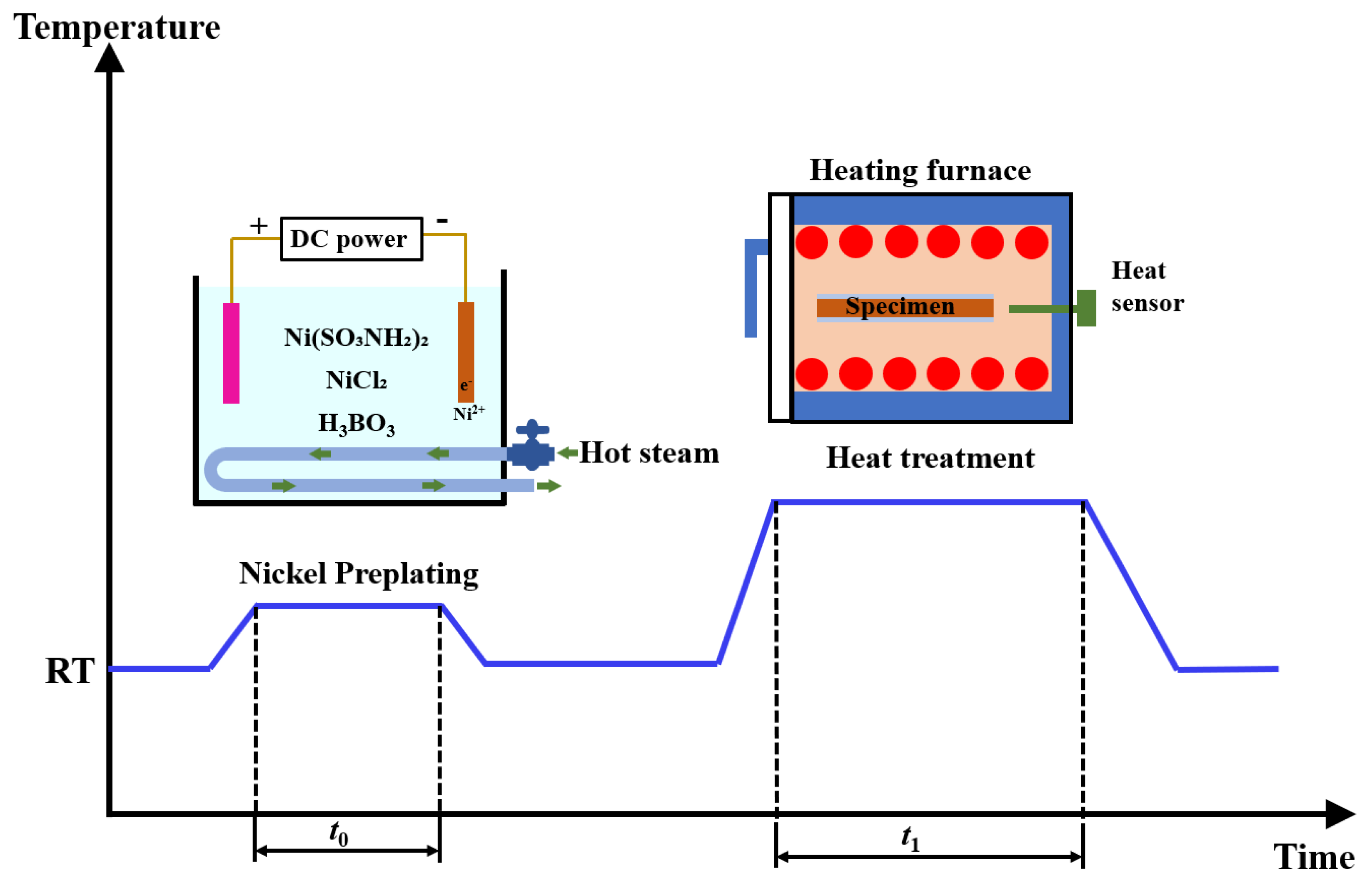
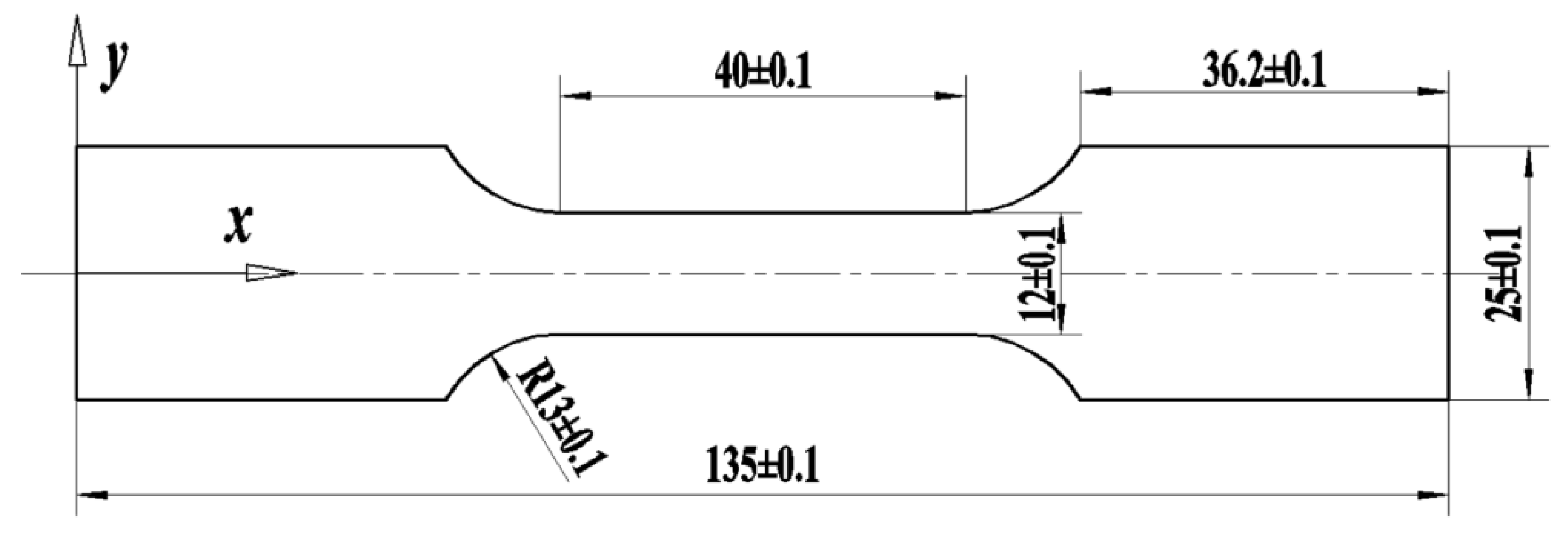
2.1. Materials and Treatment Process

The substrate material for the present work was taken from the steel sheets with 0.8 mm thickness, which was provided by the China Baowu Steel Group (Shanghai, China). The chemical composition of steel sheets is listed in Table 1. The nickel film coating on the substrate material was prepared by the electrodeposition method. Prior to electrodeposition, the steel sheets underwent the following surface preparation steps: degreasing, cleaning, and drying. The degreasing solution consists of a mixture with a concentration of 20 g/L NaOH, 30 g/L Na2CO3, and 30 g/L sodium phosphate Na3PO4. The solution was heated to 65 °C using a thermostatic water bath and maintained at this temperature for 10 min. The cleaning process was conducted with water at a temperature of 75 °C in an ultrasonic cleaner for 3 min to remove residual chemicals. The samples were dried at 60 °C for 10 min.
The electro-deposition of steel sheets were carried out in a solution containing 200 g/L Ni(SO3NH2)2, 45 g/L NiCl2), and 40 g/L H3BO3. The temperature for electro-deposition was maintained at 55 °C, utilizing high-temperature steam heating, as depicted in Figure 1. During the electro-deposition process, the solution’s pH was approximately maintained at 3.5 with a current density of 3 A/dm2. The duration of the electro-deposition was about 2 min, which was carried by direct current (DC) power. Throughout the electroplating process, the steel plate served as the cathode, while pure nickel acted as the anode. To achieve differential nickel electro-deposition thickness on both sides of the substrate, a masking technique was employed on the thinner side. This method involves the strategic placement of a shielding object to selectively restrict the deposition process on the desired surface area.
To explore the effects of heating temperature and duration on the diffusion pattern of elements at the iron–nickel interface, the samples were subjected to a heat treatment process in a furnace after electro-deposition. During the experiment, the heating furnace is first heated to the annealing temperature. Then, the sample is quickly placed into the furnace and kept at that temperature for a certain period of time. After that, it is taken out and allowed to cool in the ambient air. The annealing temperatures were set at 650 °C, 700 °C, 750 °C, and 800 °C with corresponding annealing durations of 1 min, 3 min, and 5 min for each temperature. In the subsequent analysis, the electro-deposition samples that have not undergone heat treatment were designated as the reference specimens and were named Non-T samples.

2.2. Properties Test and Microstructure Observation

For structural components, the mechanical properties of materials are of paramount importance. While enhancing the corrosion resistance of materials, their mechanical properties should not be overlooked. Uniaxial tensile tests are conducted to measure the mechanical properties of the samples following various heat treatment processes. Figure 2 shows the schematic diagram of the uniaxial tensile test specimen dimensions. The experimental apparatus used for uniaxial tensile tests was the CMT5205-5305 electronic universal testing machine, which was manufactured by MTS Systems Corporation, located in Eden Prairie, MN, USA. During the tensile process, the strain rate of the test specimen was 5 × 10⁻²·s−1.
In order to investigate the corrosion resistance of the materials, neutral salt spray tests were conducted. Within the salt spray test chamber, a 5% NaCl solution is atomized onto the surface of the test specimens, which are typically suspended on specialized racks. The pH of the solution is maintained between 6.8 and 7.2, and the temperature is kept at approximately 30 °C. After an 8 h exposure period, the specimens are left to rest for 12 h, following which they are removed from the chamber to observe the corrosion conditions on their surfaces.
To observe the diffusion behavior of elements at the iron–nickel interface under different heat treatment processes, a scanning electron microscope (SEM) produced by Zeiss (Oberkochen, Germany), equipped with an Energy Dispersive Spectrometry (EDS) analysis instrument, was utilized for characterization analysis. Prior to testing, the specimens were ground and polished to a mirror-like finish, then etched using a solution consisting of HNO3 and C2H5OH (volume ratio: HNO3: C2H5OH = 1:19). Finally, they were cleaned with anhydrous ethanol.

3. Results

3.1. Mechanical Properties

Due to the brief duration of the heat treatment, which has a minor impact on the mechanical properties of the material, specimens subjected to 5 min heat treatment at various temperatures were selected for analysis in this study. The engineering stress–strain curves of specimens in different heat treatment conditions were shown in Figure 3a. From the figure, it can be observed that the Non-T specimen exhibits the highest yield strength, reaching approximately around 165 MPa, while its elongation rate is the poorest, being approximately 37%. However, the diversity in tensile strength of the specimens under different conditions is not significant.
The yield strength and elongation rate for each condition of the specimens were tested five times, and their standard deviation fluctuations were represented using error bars. The statistical results are displayed in Figure 3b. As the heat treatment temperature increases, the strength of the specimens gradually decreases, while the elongation rate gradually increases. The reason for this phenomenon may be that heating eliminates the internal stress in the material, resulting in a reduction in the pile-up of dislocations within the material. This results in less resistance to dislocation movement during uniaxial tension, which in turn lowers the yield strength. Additionally, it also delays the initiation of cracks and the fracture of the specimens. The reduction in yield strength and increase in elongation rate indicate improved ductility and formability, which are desirable characteristics for manufacturing processes that require shaping and bending of materials without breaking [25,26], such as the fabrication of battery casings.
Figure 4 provides a comprehensive comparative analysis of the salt spray test results for specimens with and without heat treatment. The results reveal significant differences in the corrosion behavior of the specimens under examination. For the untreated specimens, the presence of noticeable rust stains on both the 3 μm and 6 μm coated surfaces after the salt spray test is a clear indication of their susceptibility to corrosion. Specifically, the 3 μm surface exhibited a more severe degree of corrosion compared to the 6 μm surface. This observation suggests that while an increase in coating thickness does provide some level of enhanced corrosion resistance, the difference in corrosion severity between the two coating thicknesses is not as pronounced as one might expect. This could imply that more effective strategies are necessary to be proposed for enhancing the corrosion resistance of the materials.
In contrast, the specimens that underwent heat treatment at 700 °C for 3 min demonstrate remarkable corrosion resistance. Virtually no signs of corrosion are observed on either the 3 μm or 6 μm coated surfaces. This finding is highly significant, as it indicates that the heat treatment process induces a diffusion layer that significantly enhances the corrosion resistance of the material’s surface. The absence of corrosion on both surfaces, regardless of coating thickness, suggests that the heat treatment has a more profound and uniform effect on corrosion resistance than the coating thickness alone. This highlights the potential benefits of incorporating heat treatment as a post-processing step in the manufacturing of materials intended for corrosive environments. The results also imply that further investigation into the microstructural changes induced by heat treatment could provide valuable insights into the mechanisms underlying the enhanced corrosion resistance observed.

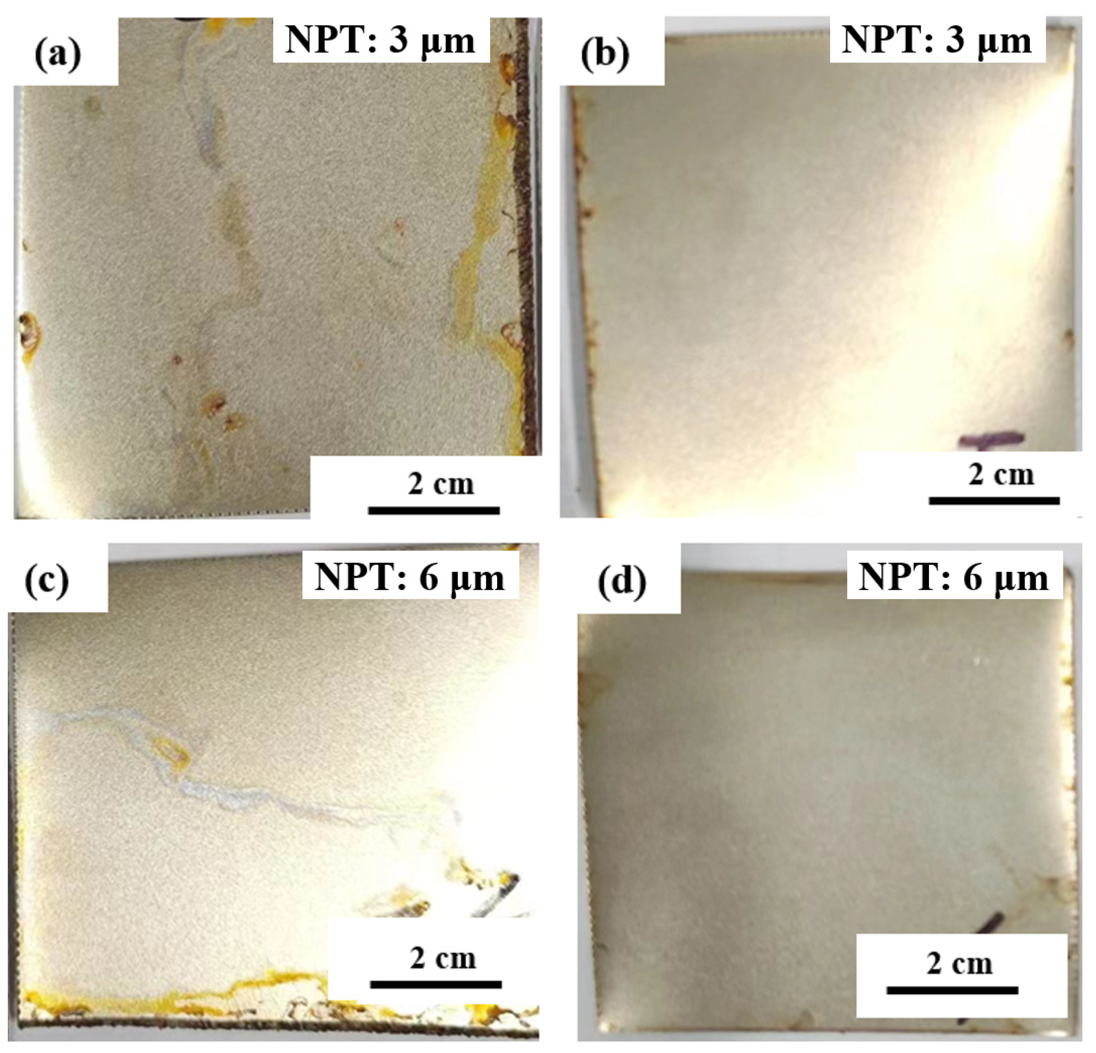
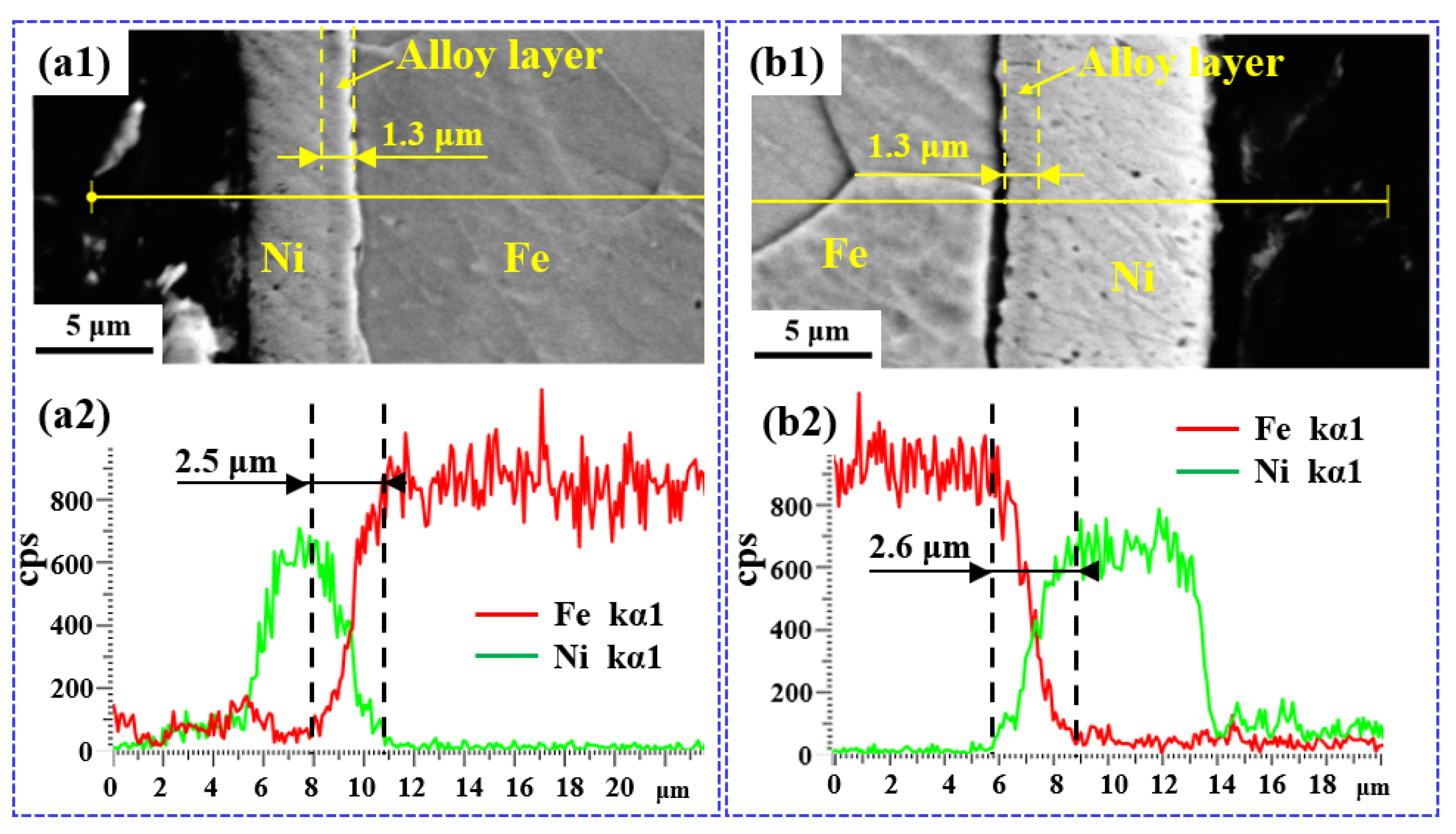
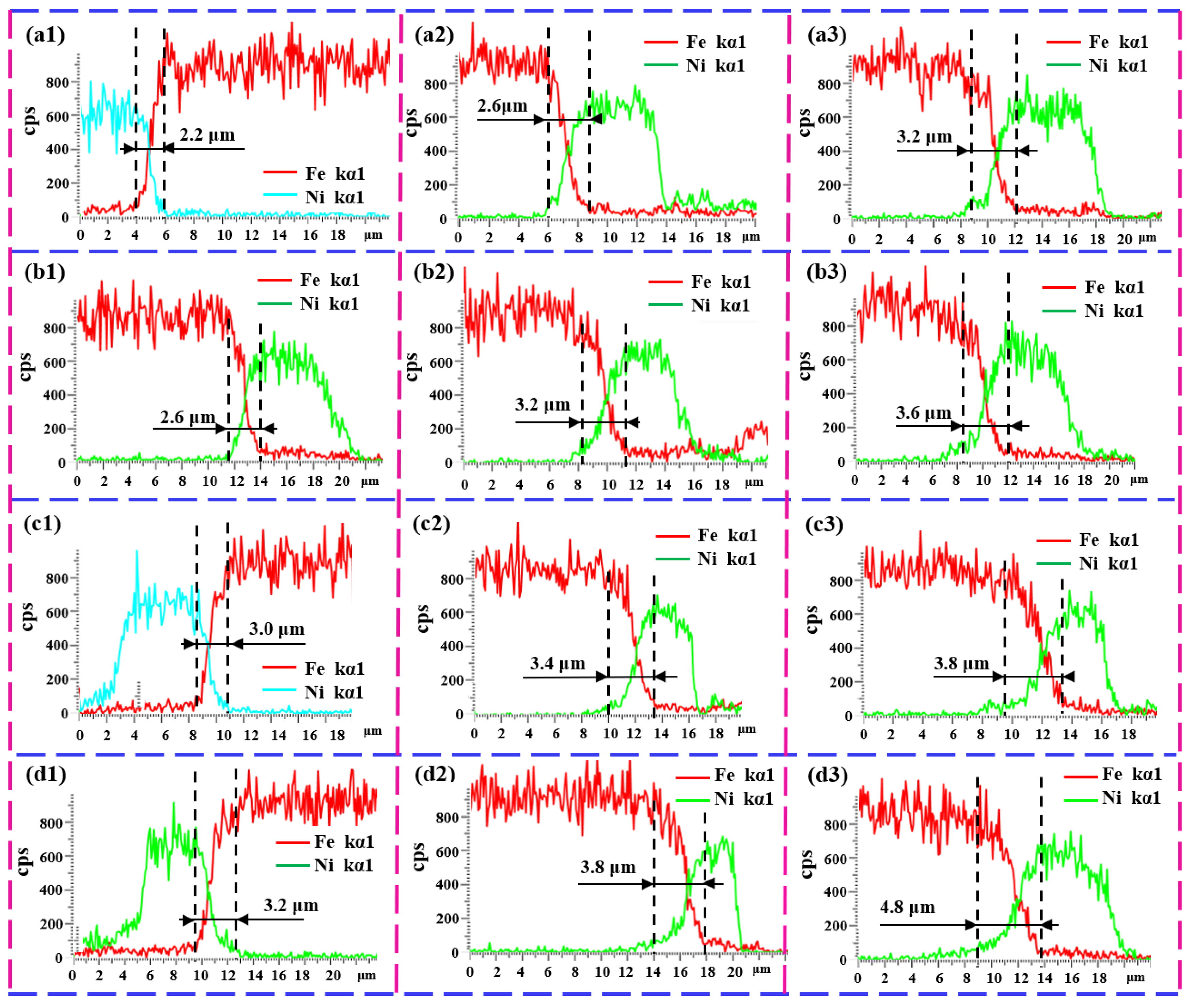
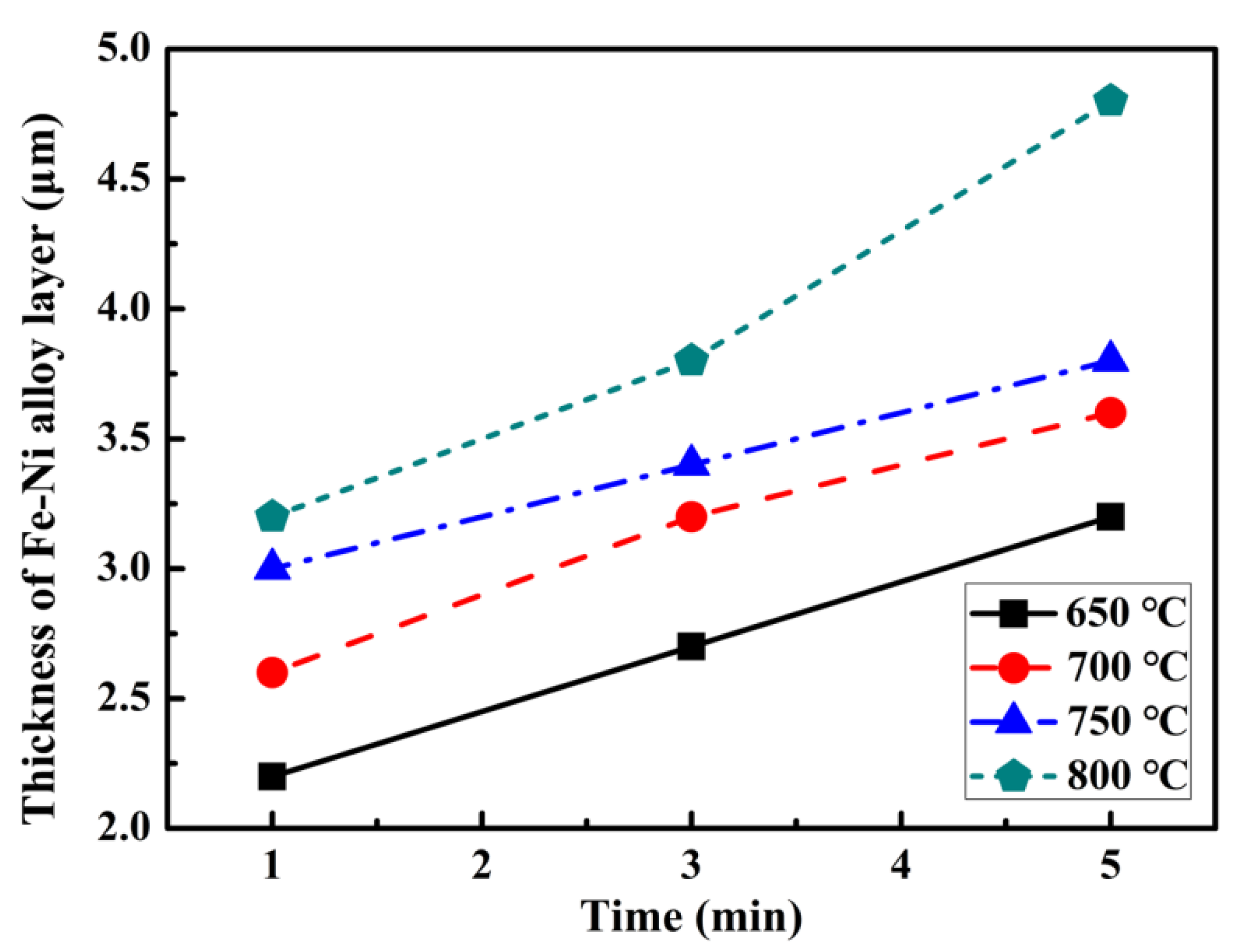
3.2. Microstructure Evolutions

Figure 5(a1) and Figure 5(b1), respectively, display the morphology of the Non-T specimen’s two sides observed by a SEM using backscattered electron imaging. It can be observed that a nickel film is adhered to the surface of the steel substrate, with the thicknesses on the two sides approximately being 6 μm and 3 μm, respectively. The reason the nickel layer is bulging in the image is due to its better corrosion resistance in the etching solution mentioned above. In contrast, the steel substrate, being corroded, has a reduced height. This differential corrosion results in the nickel layer appearing more elevated relative to the steel substrate.
In the morphology image, the iron–nickel alloy layer is not discernible, hence an energy-dispersive spectroscopy line scanning method was employed to analyze the distribution of elements. Figure 5(a2) and Figure 5(b2) exhibit energy spectrum line scanning results corresponding to the yellow line positions in Figure 5(a1) and Figure 5(b1), respectively. In the figures, the red line represents the distribution of iron elements, while the green line indicates the distribution of nickel elements. It can be observed from these figures that the changes in both lines at the iron–nickel interface are very abrupt, indicating that there is minimal formation of an alloy layer.
For comparison, the specimen heat-treated at 650 °C for 3 min were analyzed in the same method, as shown in Figure 6. It can be observed that the uncorroded nickel plating on both sides of the specimen is thicker than that of the Non-T specimen, reaching approximately 8 μm and 4.5 μm, respectively. This is primarily due to the formation of an iron–nickel alloy at the interface, which is also resistant to corrosion during the etched process. The alloy formation at the interface can lead to a thicker appearance of the nickel layer because the diffusion of iron into the nickel layer during heat treatment can increase the overall thickness of the nickel-containing layer at the surface.
Additionally, the backscattered electron images obtained from the scanning electron microscope reveal a transition layer between the steel substrate and the nickel coating, which appears darker than the nickel layer, indicating a higher atomic number contrast. These layers, approximately 1.3 μm thick, are iron–nickel alloy layers, with iron being the dominant element. The total thickness of the iron–nickel alloy layers can be determined from the energy-dispersive spectroscopy line scan images, and it is approximately 2.6 μm on both sides.
To systematically study the interdiffusion behavior of iron and nickel elements under different heat treatment processes, the thickness of the iron–nickel alloy layer formed after treatments at the temperature of 650 °C, 700 °C, 750 °C, and 800 °C for durations of 1 min, 3 min, and 5 min was roughly measured, as shown in Figure 7. Due to the near-identical thickness of the diffusion layers on both sides of the specimen, only the measurement data from one side is presented here. Higher temperatures or longer durations are not considered because they may lead to the phenomenon known as “iron leakage”. That is, the iron diffuses to the outside of the nickel film and comes into direct contact with the working environment, which may cause a decrease in corrosion resistance.
For an intuitive analysis, the thickness of the iron–nickel diffusion layer after different heat treatment processes was statistically summarized and is shown in Figure 8. From these figures, it can be observed that when the heat treatment temperature is constant, the thickness of the iron–nickel alloy layer gradually increases with the extension of the treatment time; similarly, when the treatment time is constant, the thickness of the alloy layer also gradually increases with the rise in heat treatment temperature. The main reason for this phenomenon is that the combination of higher temperature and longer time provides more energy and opportunities for atoms to overcome potential barriers and move into new positions, resulting in a thicker diffusion layer.

4. Discussion

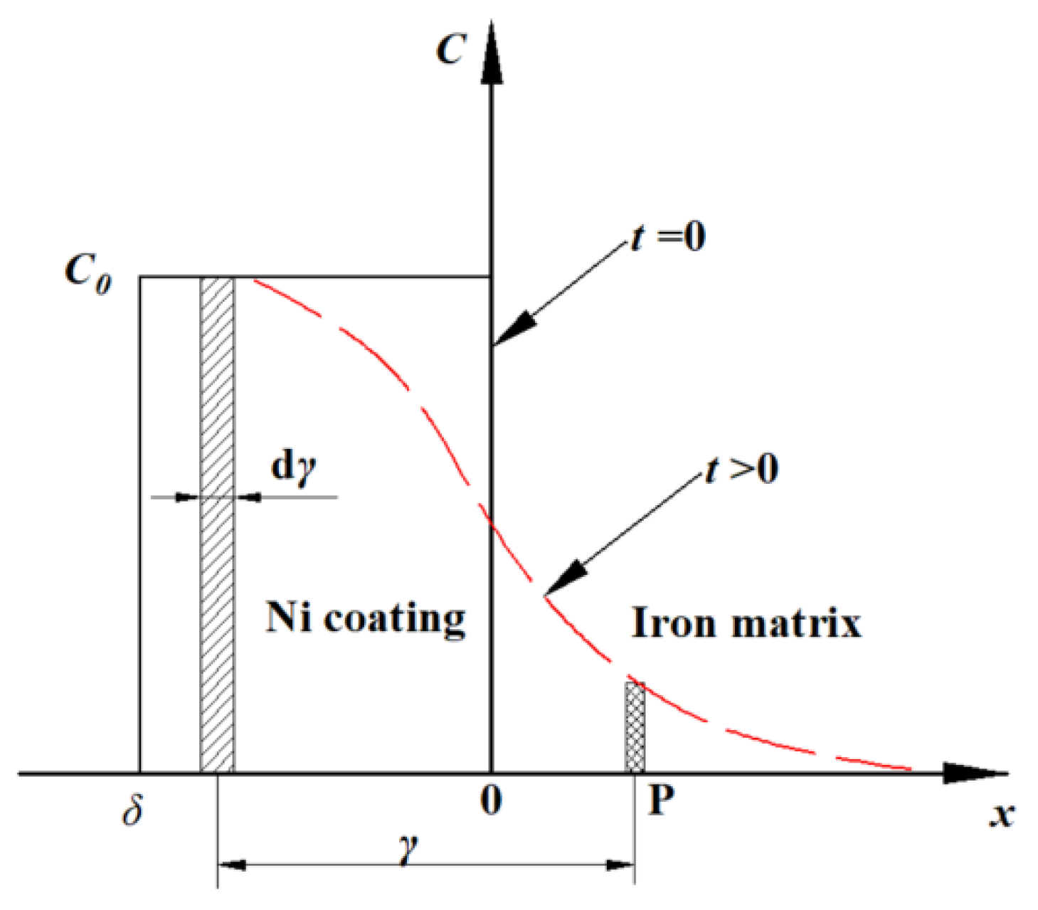
4.1. Physical Model for Annealing Diffusion at the Iron–Nickel Interface

Through experimentation, the state of the formation of an iron–nickel alloy layer under specific conditions has been obtained. The underlying mechanism needs to be elucidated by establishing a mathematical model, which can also predict the outcomes of experiments that have not yet been conducted. As shown in Figure 9, a physical model has been constructed to depict the diffusion of nickel during the annealing process of electro-deposition of steel sheets. In the established Cartesian coordinate system, the x-axis represents the spatial distance, with x = 0 denoting the interface between nickel and iron (hereinafter referred to as the center plane). A positive x value indicates the iron matrix, while a negative x value indicates the nickel coating. Considering the thickness of the iron matrix is significantly greater than that of the nickel coating, and the diffusion of nickel during the annealing process cannot penetrate the entire iron matrix, it is assumed that the iron matrix represents a semi-infinite space. The thickness of the nickel coating is set to δ.
In the Cartesian coordinate system, the y-axis represents the concentration of nickel atoms. At the initial stage of diffusion, i.e., at t = 0, it is assumed that the concentration of nickel atoms in the iron matrix is zero, while the concentration in the nickel coating is C0, with C0 = 100%. After a period of time, when t > 0, nickel elements diffuse into the iron matrix, and the concentration of nickel atoms is depicted by the red dashed line in Figure 9.

4.2. Mathematical Model for Annealing Diffusion at the Iron–Nickel Interface

Based on the aforementioned physical model, a mathematical model can be established to describe the diffusion of nickel atoms at the iron–nickel interface during the annealing process. The concentration gradient of the nickel atoms in the nickel coating varies with time during this process. Therefore, Fick’s second law is employed to analyze the diffusion behavior of nickel atoms. The diffusion equation for Ni atoms in the x-direction is given [27,28]:
C t = D 2 C x 2
where C is the concentration of Ni atoms at position x and time t. D is the diffusion coefficient for Ni atoms in the material, which is a material-specific constant that quantifies the mobility of Ni atoms within the matrix. t represents the diffusion time, which is the period over which the diffusion process occurs.
By solving the differential Equation (1), The calculated expression for the concentration of Ni atoms C is as follows,
C ( x , t ) = A t exp ( x 2 4 D t )
where A represents an undetermined coefficient. According to the initial conditions, i.e., at t = 0, the concentration of nickel atoms within the range −δ < x < 0 is C = C0, while the concentration of nickel atoms in the iron matrix where x > 0 is zero. When t > 0, nickel atoms begin to diffuse into the iron substrate. During this diffusion process, the conservation of nickel atoms must be maintained. This principle is known as mass conservation and is a fundamental requirement in the diffusion process. It implies that the total amount of nickel in the system remains constant, even though its distribution changes over time due to diffusion.
As depicted in Figure 8, an infinitesimal thickness unit dγ within the Ni coating is extracted and denotes the total mass of nickel atoms within this region as M. After the annealing treatment for a time t, the total number of nickel atoms remains constant after diffusion due to the conservation of mass. This can be expressed as:
M = C 0 d γ = δ + C ( x ) d x
If it is assumed that x2·(4Dt)−1 = β2, the total mass of nickel atoms M can be given as:
M = 2 A D δ + exp ( β 2 ) d β = C 0 d γ
where 0 + exp ( β 2 ) d β = π , δ 0 exp ( β 2 ) d β = π 2 e r f ( δ ) , the erf(z) function is the error function. By solving Equation (4), the value of coefficient A is obtained as follows:
A = C 0 d γ π D 1 + e r f ( δ )
Assuming there is a point P in the iron matrix at a distance x from the iron–nickel interface, and the distance between this point and the infinitesimal thickness unit with is γ. The concentration at point P due to the diffusion from the infinitesimal thickness unit can be expressed as:
C ( x , t ) = C 0 d γ π D t 1 + e r f ( δ ) exp ( γ 2 4 D t )
Thus, the diffusion from the coating can be regarded as the superposition of diffusion results from an infinite number of infinitesimal diffusion sources. After the annealing treatment for a duration of t, the total concentration at point P can be represented as:
C ( x , t ) = C 0 π D t 1 + e r f ( δ ) x x + δ exp ( γ 2 4 D t ) d γ
As indicated by Figure 8, the range of values for γ is from x to x + δ. By solving Equation (7), we can obtain the following result:
C ( x , t ) = C 0 1 + e r f ( δ ) e r f x + δ 2 D t e r f x 2 D t
In this study, the relevant parameters are as follows. C0 is 1, δ is six micrometers, and D is a variable that changes with temperature and concentration [29].

4.3. Mathematical Model Solving and Results Analysis

To solve Equation (8) and fit the calculated results with experimental measurements, the average diffusion coefficient of nickel atoms at different temperatures was determined. Taking the example of annealing at 750 °C for one minute, Figure 10a presents the fitting curve between the test results and the calculated results. In the figure, the black solid line represents the experimental measurement results, while the red solid line represents the calculated results. It can be observed that the two curves exhibit a high degree of congruence, particularly near the center plane. By employing the same method to successively fit the experimental results after different annealing treatments, the diffusion coefficients corresponding to each condition can be obtained as follows. At a temperature of 650 °C, 700 °C, 750 °C, and 800 °C, the average diffusion coefficient D are approximately 4.4 × 10⁻¹⁶ m2·s−1, 6.7 × 10⁻¹⁶ m2·s−1, 7.9 × 10⁻¹⁶ m2·s−1 and 1.26 × 10⁻¹⁵ m2·s−1, respectively.
It is evident that within the scope of this experiment, as the temperature increases, the diffusion coefficient of nickel atoms gradually increases. This trend is consistent with the fundamental principles of diffusion, which state that higher temperatures provide greater kinetic energy to atoms, leading to more frequent and energetic jumps that facilitate the diffusion process. Additionally, the diffusion coefficients of nickel atoms obtained in this experiment, ranging from 4.4 × 10⁻¹⁶ m2·s−1 to 1.26 × 10⁻¹⁵ m2·s−1 at temperatures between 650 °C and 800 °C, are basically in agreement with those reported in the literature, such as the values of 1.28 × 10⁻¹⁶ m2·s−1 to 8.48 × 10⁻¹⁴ m2·s−1 at 650 °C to 850 °C observed by Sun et al. [30,31].
In addition, the relationship between the diffusion coefficient of iron–nickel and temperature follows the Arrhenius equation, as shown below: D = D0exp(−ΔH/kT) [28], where D0 is the pre-exponential factor. k and are Boltzmann’s constant and the absolute temperature, respectively. ΔH is the activation enthalpy, which can be determined by plotting lnD versus, 1/T applying the least-squares method for linear fitting. Calculating from the slope of the fitted line, the activation enthalpy ΔH is about 268.3 kJ/mol.
Figure 10b illustrates the calculated concentration distribution curve of nickel after annealing treatment at 800 °C. It can be observed that as the processing time increases, the slope of the curve near the center plane decreases, which implies that the thickness of the formed Fe-Ni alloy layer gradually increases. Additionally, the concentration of the nickel atoms at x = 0 is 0.5 for all curves, indicating that the center position of the Fe-Ni alloy layer formed by diffusion is fixed. The curves are approximately symmetric about the center at (0, 0.5), from which it can be inferred that the thickness of the Fe-Ni alloy layer is at most twice that of the electroplated nickel layer before “iron leakage”.
To further analyze the diffusion process of nickel atoms during annealing, the increase in nickel atom concentration at different positions after various annealing durations is compared, as shown in Figure 11. Figure 11a illustrates the variation in nickel atom concentration after annealing treatments at different temperatures for five minutes. It can be observed that there is no change in nickel concentration at the center plane position (x = 0), while in the region where x > 0, the change in nickel atom concentration is positive, indicating an increase in nickel atom concentration in this area after the annealing treatment. In the region where x < 0, the change in nickel atom concentration is negative, indicating a decrease in nickel atom concentration in this area following the annealing treatment.
The peak in the change of nickel atom concentration increases with the rise in treatment temperature, reaching a maximum value of up to 0.26 when the annealing temperature is 800 °C. The peak in the variation of nickel atom concentration shifts away from the central position with the increase in treatment temperature. Figure 11b illustrates the pattern of nickel atom diffusion as a function of time at various positions during annealing at 800 °C. In the figure, the green surface indicates an increase in nickel atom concentration, while the red surface indicates a decrease in nickel atom concentration. It could be observed that there is a net movement of nickel atoms from the region x < 0 to the region x > 0, leading to an increase in concentration in the latter and a corresponding decrease in the former. In addition, as the annealing time increases, the diffusion of nickel atoms gradually increases.

5. Conclusions

In this study, the iron–nickel interface diffusion behavior of electroplated nickel steel during annealing were investigated by microstructural characterization and mathematical modeling. The major conclusions are summarized as follows:
(1) Compared to mere electrodeposited nickel, the subsequent brief annealing treatment can further enhance the corrosion resistance of carbon steel. Meanwhile, annealing treatment slightly reduces the yield strength of materials while enhancing its ductility.
(2) Through annealing treatment, an iron–nickel alloy layer can be formed in electroplated nickel steel, with the thickness of the alloy layer increasing with higher annealing temperatures and extended durations. Consequently, a desired alloy layer can be achieved by controlling the annealing process parameters.
(3) Solving the kinetic model of nickel diffusion reveals that the diffusion coefficient increases with the increase in annealing temperature. The nickel concentration at the center plane remains constant at 0.5, and the maximum thickness of the formed iron–nickel alloy layer, without “iron leakage”, is up to twice that of the electroplated nickel layer.

Author Contributions

Conceptualization, F.Z. and F.W.; Methodology, W.W. and J.L.; Software, P.Z.; Validation, P.Z. and J.L.; Formal analysis, P.Z. and J.L.; Investigation, W.W. and J.L.; Resources, F.Z. and F.W.; Data curation, W.W. and J.L.; Writing—original draft, W.W.; Writing—review and editing, F.Z. and F.W.; Visualization, P.Z.; Supervision, F.W.; Project administration, F.Z.; Funding acquisition, W.W. and F.Z. All authors have read and agreed to the published version of the manuscript.

Funding

This work was financially supported by the Hubei Provincial Department of Education Science and Technology Research Project (Grant no. D20232703, B2023160), the Natural Science Foundation of Hubei Province (Grant no. JCZRYB202501251).

Data Availability Statement

The original contributions presented in this study are included in the article. Further inquiries can be directed to the corresponding authors.

Conflicts of Interest

The authors declare no conflicts of interest.

References

  1. Kozłowska, A.; Grajcar, A.; Opara, J.; Kaczmarczyk, J.; Janik, A.; Radwański, K. Mechanical behaviour and micromechanical modelling of medium-Mn steel microstructure evolution. Int. J. Mech. Sci. 2022, 220, 107151. [Google Scholar] [CrossRef]
  2. Wang, Y. Study on Zn-Ni Electrodeposited coating on 40Mn Steel as Construction Material and its Corrosion Resistance in Simulated Concrete Pore Solution. Int. J. Electrochem. Sci. 2022, 17, 220752. [Google Scholar] [CrossRef]
  3. Ren, S.; Cui, M.; Chen, X.; Mei, S.; Qiang, Y. Comparative study on corrosion inhibition of N doped and N,S codoped carbon dots for carbon steel in strong acidic solution. J. Colloid Interface Sci. 2022, 628, 384–397. [Google Scholar] [CrossRef]
  4. Gao, Q.; Yu, X.; Jiang, H.; Zhang, S.; Yu, Q.; Wang, C.; Tang, Y.; Zhang, L.; Song, Y.; Li, L.; et al. Local corrosion behavior of pipeline steel under deposition layer in produced water of Alkali/ Surfactants/Polymers. Colloids Surf. Physicochem. Eng. Asp. 2023, 679, 132609. [Google Scholar] [CrossRef]
  5. Liu, L.; Li, W.; Deng, Z.; Xu, S.; Xu, Y.; Zeng, L.; Li, D.; Yang, Y.; Zhong, Z. Effect of moisture on corrosion behavior of Q235 steel in bentonite clay. Int. J. Electrochem. Sci. 2023, 18, 100164. [Google Scholar] [CrossRef]
  6. Govindan, S.; Boopathi, M.; Venkatesh, A.P.; Maridurai, T.; Sathish, T.; Balakrishnan, E. Statistical analysis of electrodeposited nickel coating to S275JR grade mild steel. Mater. Today Proc. 2021, 46, 4159–4164. [Google Scholar] [CrossRef]
  7. Naderi, J.; Sarhan, A.A.D. Measure and evaluate the hardness of the electrodeposited Nickel-Phosphorous (Ni-P) thin film coating on carbon steel alloy for automotive applications. Measurement 2019, 139, 490–497. [Google Scholar] [CrossRef]
  8. Kumar, M.; Sidpara, A.; Racherla, V. Improving surface finish and wear resistance of electroless nickel plating using flexible abrasive tool. Wear 2024, 546–547, 205326. [Google Scholar] [CrossRef]
  9. Hao, J.-Z.; Xu, J.-J.; Cao, H.-L.; Miao, H.; Xu, S.-A. The effects of P and metal elements in electroless nickel-based alloys on the formation of Ti/Zr conversion coating. J. Alloys Compd. 2024, 982, 173761. [Google Scholar] [CrossRef]
  10. Awasthi, S.; De, S.; Pandey, S.K. Electrodeposited carbon nanostructured nickel composite coatings: A review. Heliyon 2024, 10, e26051. [Google Scholar] [CrossRef] [PubMed]
  11. Sudagar, J.; Lian, J.; Sha, W. Electroless nickel, alloy, composite and nano coatings—A critical review. J. Alloys Compd. 2013, 571, 183–204. [Google Scholar] [CrossRef]
  12. Faraji, S.; Ani, F.N. The development supercapacitor from activated carbon by electroless plating—A review. Renew. Sustain. Energy Rev. 2015, 42, 823–834. [Google Scholar] [CrossRef]
  13. Zhou, L.Q.; Li, Y.P.; Zhou, Y.C. Numerical Analysis of Electrodeposited Nickel Coating in Multistage Drawing Processes. J. Eng. Mater. Technol. 2005, 127, 233–243. [Google Scholar] [CrossRef]
  14. Ren, Q.-Q.; Baik, S.-I.; An, D.; Isheim, D.; Zhu, M.; Krakauer, B.W.; Seidman, D.N. The effects of heat-treatment parameters on the mechanical properties and microstructures of a low-carbon dual-phase steel. Mater. Sci. Eng. A 2023, 888, 145801. [Google Scholar] [CrossRef]
  15. Santhosh, R.; Geetha, M.; Nageswara Rao, M. Recent Developments in Heat Treatment of Beta Titanium Alloys for Aerospace Applications. Trans. Indian Inst. Met. 2017, 70, 1681–1688. [Google Scholar] [CrossRef]
  16. Carvalho, A.L.M.; Renaudin, L.B.; Zara, A.J.; Martins, J.P. Microstructure analysis of 7050 aluminum alloy processed by multistage aging treatments. J. Alloys Compd. 2022, 907, 164400. [Google Scholar] [CrossRef]
  17. Ashrafizadeh, S.M.; Eivani, A.R.; Jafarian, H.R.; Zhou, J. Improvement of mechanical properties of AA6063 aluminum alloy after equal channel angular pressing by applying a two-stage solution treatment. Mater. Sci. Eng. A 2017, 687, 54–62. [Google Scholar] [CrossRef]
  18. Ma, W.; Wang, B.; Yang, L.; Tang, X.; Xiao, W. Influence of solution heat treatment on mechanical response and fracture behaviour of aluminium alloy sheets: An experimental study. Mater. Des. 2015, 88, 1119–1126. [Google Scholar] [CrossRef]
  19. Zhang, W.; Li, W.; Liu, H.; He, T.; Deng, S.; Tian, H.; Cao, W. Microstructure effects on improving rolling contact fatigue by a double-quenching heat treatment process for GCr15 steel. Tribol. Int. 2024, 194, 109519. [Google Scholar] [CrossRef]
  20. Jiang, P.; Xu, Z.; Li, Z.; Pan, H.; Zhang, Y. Microstructure, mechanical properties and wear resistances of 40CrNiMoA steel affected by cyclic quenching treatment. Mater. Today Commun. 2024, 40, 109799. [Google Scholar] [CrossRef]
  21. Ramana, M.V.; Rao, G.K.M.; Sagar, B.; Panthangi, R.K.; Kumar, B.V.R.R. Optimization of surface roughness and tool wear in sustainable dry turning of Iron based Nickel A286 alloy using Taguchi’s method. Clean. Eng. Technol. 2021, 2, 100034. [Google Scholar] [CrossRef]
  22. Singla, Y.K.; Maughan, M.R.; Arora, N.; Dwivedi, D.K. Enhancing the wear resistance of iron-based alloys: A comprehensive review of alloying element effects. J. Manuf. Process. 2024, 120, 135–160. [Google Scholar] [CrossRef]
  23. Prasad, M.J.N.V.; Chokshi, A.H. On the exothermic peak during annealing of electrodeposited nanocrystalline nickel. Scr. Mater. 2011, 64, 544–547. [Google Scholar] [CrossRef]
  24. Julie, S.; Dash, M.K.; Wasekar, N.P.; David, C.; Kamruddin, M. Effect of annealing and irradiation on the evolution of texture and grain boundary interface in electrodeposited nanocrystalline nickel of varying grain sizes. Surf. Coat. Technol. 2021, 426, 127770. [Google Scholar] [CrossRef]
  25. Singh, A.K.; Bhattacharya, B.; Biswas, S. High strength, ductility and sheet formability by normalizing and quenching of low carbon microalloyed dual-phase steel. Mater. Sci. Eng. A 2024, 890, 145848. [Google Scholar] [CrossRef]
  26. Murty, S.V.S.N.; Rao, B.N.; Kashyap, B.P. Improved ductile fracture criterion for cold forming of spheroidised steel. J. Mater. Process. Technol. 2004, 147, 94–101. [Google Scholar] [CrossRef]
  27. Vermolena, F.; Vuikb, K. A numerical method to compute the dissolution of second phases in ternary alloys. J. Comput. Appl. Math. 1998, 93, 123–143. [Google Scholar] [CrossRef]
  28. Wu, W.; Song, Y.; Zhou, P.; Lu, J.; Yu, Y.; Hua, L. Rapid dissolution kinetic of the second phases in high-strength aluminum alloy by electroshock treatment. J. Mater. Sci. 2024, 59, 17259–17277. [Google Scholar] [CrossRef]
  29. Zhang, S.; Xu, M.; Zhao, X.; Li, Y. Diffusion mechanism and rules of nickel on surface of low carbon steel. Heat Treat. Met. 2023, 48, 121–128. [Google Scholar] [CrossRef]
  30. Sun, J.; Chen, D.; Ma, Y. Strain-Induced Diffusion of Nickel in Nanocrystalline Fe Produced by High Energy Shot Peening. Rare Met. Mater. Eng. 2017, 46, 596–600. [Google Scholar]
  31. Sun, J. Diffusion of Nickel in Nanocrytalline Iron. Mater. Rep. B 2014, 28, 159–162. [Google Scholar]
Figure 1. Schematic diagram of pre-plating nickel and annealing process for steel strips.
Metals 15 00211 g001
Figure 2. Schematic diagram of the geometry and dimensions of the uniaxial tensile test specimen (Unit: cm).
Metals 15 00211 g002
Figure 3. Comparison on the mechanical properties of pre-plated nickel steel after different processes (a) Engineering stress–strain curves; (b) comparison of yield strength and maximum engineering strain before fracture.
Metals 15 00211 g003
Figure 4. Comparative results of salt spray tests on specimens with and without heat treatment (a,c) Non-T specimen surfaces with NPT 3 μm and 6 μm, respectively; (b,d) heat treatment specimen surfaces with NPT 3 μm and 6 μm, respectively; (NPT: Nickel Plating Thickness).
Metals 15 00211 g004
Figure 5. Morphology and elemental analysis of the cross-section of nickel-plated steel plate without heat treatment: (a1,b1) SEM morphology images; (a2,b2) EDS line scanning results corresponding to the yellow lines in (a1) and (b1), respectively.
Metals 15 00211 g005
Figure 6. Morphology and elemental analysis of the section of nickel-plated steel plate after heat treatment at 650 °C for 3 minutes: (a1,b1) SEM morphology images; (a2,b2) EDS line scanning results corresponding to the yellow line positions in (a1) and (b1), respectively.
Metals 15 00211 g006
Figure 7. Distribution of Fe and Ni elements in the thickness direction after different heat treatment processes: EDS line scanning results for (a1) 650 °C/ 1 min; (a2) 650 °C/3 min; (a3) 650 °C/ 5 min; (b1) 700 °C/ 1 min; (b2) 700 °C/3 min; (b3) 700 °C/ 5 min; (c1) 750 °C/ 1 min; (c2) 750 °C/3 min; (c3) 750 °C/ 5 min; (d1) 800 °C/ 1 min; (d2) 800 °C/3 min; (d3) 800 °C/5 min.
Metals 15 00211 g007
Figure 8. Statistics of the thickness of Fe-Ni alloy layer after different heat treatment processes.
Metals 15 00211 g008
Figure 9. Schematic diagram of the physical model for annealing diffusion at the iron–nickel interface.
Metals 15 00211 g009
Figure 10. Nickel atom concentration distribution curve simulation calculation: (a) Comparison of experimental and computational results for nickel distribution concentrations after one minute of annealing at 750 °C; (b) Nickel concentration distribution curves after annealing treatments at 800 °C for various durations.
Metals 15 00211 g010
Figure 11. Calculation of the variation in nickel atom concentration during the annealing process: (a) Variation in nickel atom concentration after annealing at different temperatures for 5 min; (b) The relationship between the change in nickel concentration and annealing time and position after annealing at 800 °C.
Metals 15 00211 g011
Table 1. Chemical composition of the substrate steel sheets.
CompositionCSiMnPSAlFe
wt.%0.0820.0110.2150.01310.00790.076Bal.
Disclaimer/Publisher’s Note: The statements, opinions and data contained in all publications are solely those of the individual author(s) and contributor(s) and not of MDPI and/or the editor(s). MDPI and/or the editor(s) disclaim responsibility for any injury to people or property resulting from any ideas, methods, instructions or products referred to in the content.

