Article

The Impact of Structural Units on Copper Grain Boundary–Dislocation Interactions

1
Department of Engineering Mechanics, School of Naval Architecture, Ocean and Civil Engineering, Shanghai Jiao Tong University, Shanghai 200240, China
2
State Key Laboratory of Ocean Engineering, Shanghai Jiao Tong University, Shanghai 200240, China
*
Author to whom correspondence should be addressed.
Metals 2025, 15(12), 1291; https://doi.org/10.3390/met15121291
Submission received: 17 October 2025 / Revised: 14 November 2025 / Accepted: 22 November 2025 / Published: 25 November 2025

Abstract

A molecular dynamics approach was employed to investigate the interaction behavior between tilt-[110] copper grain boundaries (GBs) and dislocations, with particular emphasis on elucidating the role of GB structural unit (SU) types in the mechanisms of dislocation absorption and transmission. The results reveal that singular GBs composed of continuous and uniform B-type or C-type SUs exhibit a pronounced ability to absorb dislocations, whereby incident dislocations are fully absorbed by the GB and prevented from transmitting across it. In contrast, for discrete GBs containing both C SUs and intrinsic stacking fault facets, the dislocation accommodation capacity of the GB is closely related to the number of C SUs within the discrete region. Multiple continuous C SUs can effectively facilitate dislocation absorption and energy dissipation through a synergistic linkage mechanism. This study underscores the critical role of GB SUs in governing GB–dislocation interactions and provides atomic-scale insights into the microstructural regulation mechanisms of GBs during plastic deformation.

Graphical Abstract

1. Introduction

Grain boundaries (GBs) are interfaces separating adjacent grains in polycrystalline materials and represent typical two-dimensional defects in crystal structures, within which atomic arrangements generally exhibit a high degree of disorder and structural distortion. This disordered configuration results in elevated potential energy states of GB atoms, making them preferential sites for dislocation nucleation while simultaneously serving as obstacles to dislocation transmission. Consequently, the interactions between GBs and dislocations play a crucial role in determining the key mechanical properties of polycrystalline materials [1,2,3,4].
Due to the limited spatial and temporal resolution of experimental techniques, direct atomic-scale observation of GB evolution and its influence on dislocation behavior remains challenging. In recent years, molecular dynamics (MD) simulations have emerged as a powerful tool for investigating the underlying mechanisms of GB–dislocation interactions. MD simulations can systematically analyze the collision process between an individual dislocation and a specific GB, reveal the corresponding atomic structural evolution and dislocation reaction pathways, and precisely track the variation in Burgers vectors throughout the process. This approach provides atomistic insight into GB responses under multifactor coupling effects [5].
Atoms at GBs tend to move toward lower-energy configurations, leading to the formation of characteristic boundary structures [6]. Early studies by Smith [7], Ashby [8], and Pond [9] laid the foundation for understanding GB structures. Sutton and Vitek [10,11] introduced the concept of the Structural Unit Model (SUM) in 1983. Based on this model, Rittner et al. [12] investigated tilt GBs in copper (Cu) and aluminum (Al) and identified five basic structural units (SUs), labeled A, B, C, D, and E type SUs, as shown in Figure 1. The formation and periodic distribution of SUs can be viewed as a geometrical manifestation of the Coincidence Site Lattice (CSL) theory [13], in which atomic positions at the GB repeat periodically, giving rise to geometric matching and periodic patterns in both atomic arrangement and energy distribution [14].
The detailed mechanisms of GB–dislocation interactions largely depend on the GB’s microscopic characteristics, including plane type, internal structure, energy, and free volume [15,16]. These factors jointly determine the trajectory, energy evolution, and reaction products of a dislocation as it approaches a GB. Koning et al. [5,17] were among the first to employ MD simulations for investigating GB–dislocation interactions, showing that whether a dislocation can cross the GB is governed by GB geometry, local shear stress and residual stress distribution. Their findings are consistent with the results of in situ transmission electron microscopy (TEM) experiments by Lee et al. [18,19,20,21]. Dewald and Curtin [22,23,24] utilized the Concurrent Atomistic–Discrete Dislocation (CADD) method to simulate the impact of dislocations on tilt GBs in Al, demonstrating that the interaction mechanism is strongly affected by dislocation pile-ups; specifically, increasing dislocation density alters the absorption and transmission modes of the GB. Shimokawa [25] employed atomic simulations to perform tensile and compressive loading tests on aluminum bi-crystals, and found that he Σ15 boundary can change its structure to the energetically stable Σ11 structure by emitting dislocations. More recently, Jin et al. [26,27] used MD simulations to investigate the interactions of screw and 60° dislocations with coherent twin boundaries in Al, Cu, and Ni, revealing that dislocation transmission or dissociation at the GB primarily depends on the dislocation character and the material’s stacking-fault energy.
Although previous studies have partially elucidated the influence of GB configurations on GB–dislocation interactions, the role of SUs in governing these mechanisms remains insufficiently clarified.
Motivated by this, the present study aims to elucidate the interaction mechanisms between dislocations and GBs containing different types of SUs through atomistic simulations. The paper is organized as follows: first, the construction of atomic models and the details of the MD simulation procedures are introduced; then, the interactions between dislocations and GBs composed of various SUs are analyzed, with emphasis on dislocation absorption, transmission, and dissociation behaviors under different GB configurations; finally, the findings are summarized.

2. Methodology

The MD simulations in this study were performed using the LAMMPS (version: 7 Feb 2024) [28], while the visualization of atomic-scale structural evolution and dislocation dynamics was carried out using OVITO (version: 3.0.0) [29]. The embedded-atom method (EAM) potential for Cu proposed by Mishin et al. [30] was adopted. Based on extensive experimental and atomic simulation data, this EAM potential exhibits high accuracy and reliability in reproducing the lattice constant, elastic constants, and stacking fault energy (SFE) of Cu [31].

2.1. Model Construction

Typical tilt-[110] Cu bi-crystal models were constructed based on the CSL theory [13]. The two grains were arranged on the left and right sides of the simulation box, and the dimensions along X, Y, and Z directions were 800 Å × 400 Å × 3 2 α Å , where α represents the Cu lattice constant (3.615A in this study). The crystallographic orientations of the initial model were X: 1   1 ¯   2 ¯ , Y: 1 ¯   1   1 ¯ , and Z: 1   1   0 . Grain 1 remains fixed, while grain 2 is rotated about the Z-axis.as illustrated in Figure 2a.
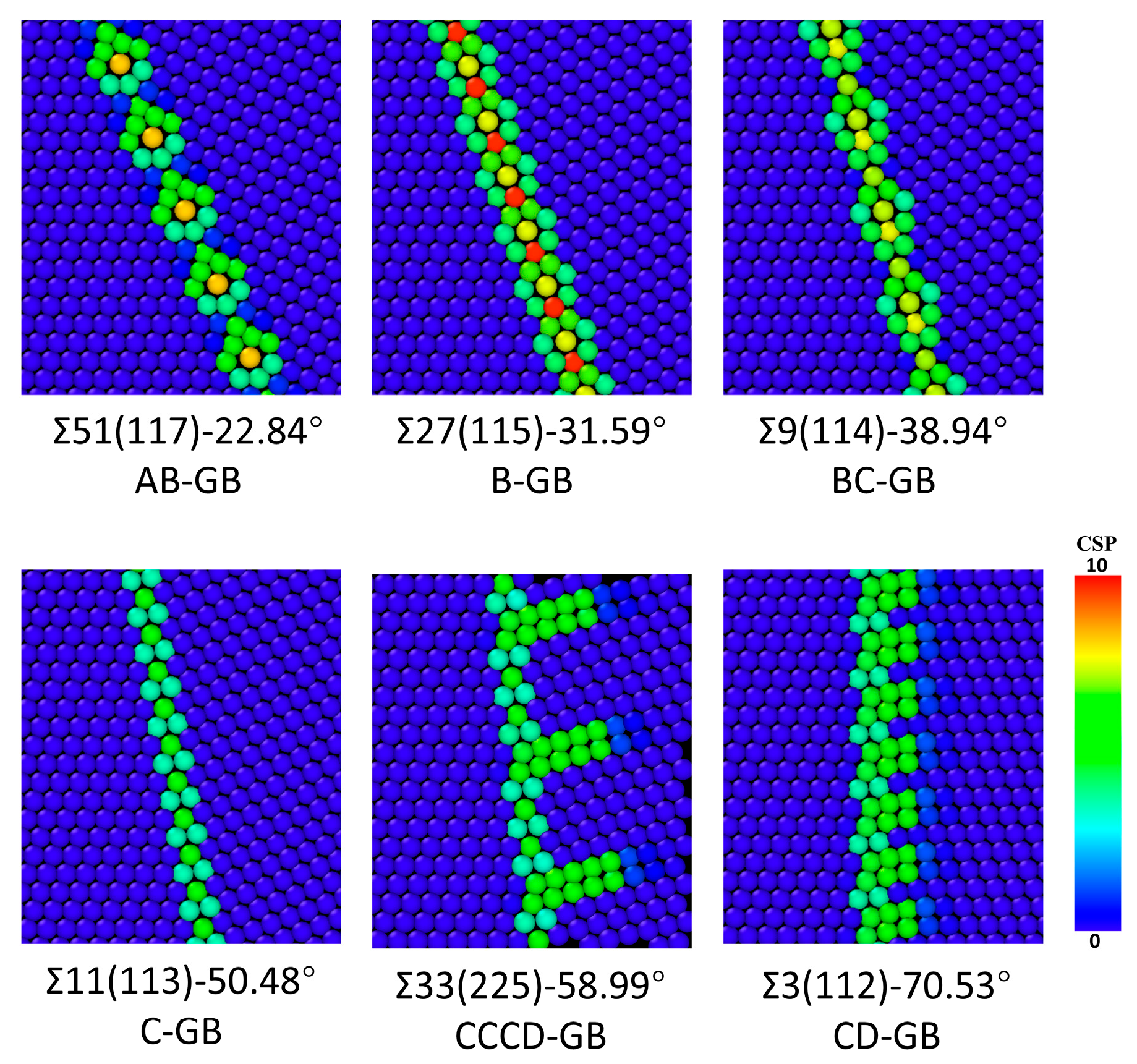
After constructing the initial GB model, the system energy was minimized using the Conjugate Gradient (CG) algorithm [32]. Prior to calculating GB energy, the model was relaxed for 10 ps under an Isothermal–isobaric ensemble (NPT ensemble) to release residual stresses near the GB region. During relaxation, allowing atoms to move freely only along the X direction to release local pressure at the interface. Following minimization, the GB energy was computed using the atoms within the red dashed region highlighted in Figure 2b to ensure that the calculated value reflected the intrinsic GB characteristics. In total, six type bi-crystal models were employed in this study; namely, Σ51(117)-22.84°, Σ27(115)-31.59°, Σ9(114)-38.94°, Σ11(113)-50.48°, Σ33(225)-58.99°, and Σ3(112)-70.53°, comprising A, B, C, and D SUs. GBs containing the E-type SU were excluded due to such boundaries exhibit distinct mechanical responses compared to the others [33,34]. In the model nomenclature, Σ51 denotes the CSL parameter, where a smaller value corresponds to a higher degree of atomic coincidence at the GB; (117) represents the Miller indices of the GB plane; and 22.84° specifies the misorientation angle between the two grains. Among these, the Σ51(117)-22.84° GB contains both A and B type SUs, arranged periodically in an A–B–A–B sequence. In this work, this configuration is designated as the AB-GB model. The structural information of all models is summarized in Table 1, and the corresponding atomic configurations of the GBs are shown in Figure 3, with atoms colored by the centrosymmetry parameter (CSP) method [35].
After full relaxation, a screw dislocation was introduced into grain 1 to study its interaction with the GB. Based on the geometry of the face-centered cubic (FCC) lattice, the smallest lattice translation vector is α / 2 [ 110 ] . Once the insertion position was determined, atoms in the upper and lower halves of grain 1 were displaced along the Burgers vector direction, generating an α / 2 [ 110 ] screw dislocation extending along the Z direction, as shown in Figure 2b. The dislocation line was parallel to its Burgers vector, and its initial position was set more than 200 Å away from the GB to prevent unwanted interactions during relaxation [26,36].
Due to the relatively low SFE of Cu [30,31], the pre-inserted full dislocation spontaneously dissociated into two 30° Shockley partial dislocations after energy minimization: a leading and a trailing partial dislocation. The dissociation reaction can be expressed as:
a 2 110 a 6 2   1   1 ¯ L + a 6 1   2   1 T

2.2. Simulation Process

Periodic boundary conditions were applied along the Z direction, while free boundary conditions were imposed along the X and Y directions. Atoms within 10 Å from the top and bottom surfaces along the Y-axis were fixed as rigid bodies to apply external loading and to prevent rigid-body translation of the entire system. Consistent with previous findings [26,36], when the system size exceeds 200 Å under free boundary conditions, the influence of surface atoms on the pre-existing dislocation becomes negligible. Before loading, energy minimization was performed again using the CG algorithm, followed by a 10 ps relaxation under a Canonical ensemble (NVT ensemble). According to Gao et al. [37], temperature affects the thermal stability of atomistic simulations, and although minor differences exist between results obtained at 0 K and 600 K, the general trends remain consistent. Therefore, the system temperature was maintained at approximately 10 K to ensure thermal stability and to minimize noise from thermal fluctuations.
A uniform shear deformation was applied by moving the upper rigid-body atoms along the XZ plane in a direction parallel to the Burgers vector of the pre-existing dislocation, the applied shear strain rate was set to 1 × 10⁹ s−1, ensuring that dislocation motion and GB response could be adequately captured within the MD timescale. The entire loading process was conducted under an NVT ensemble with a Nose–Hoover thermostat [38] used to maintain temperature stability throughout the simulation. The centrosymmetry parameter (CSP) method [35] was employed to identify and visualize lattice defects, and the Dislocation Extraction Algorithm (DXA) [39,40] was utilized to automatically detect and classify dislocation lines within the simulation cell, enabling quantitative characterization of dislocation-GB reactions.

3. Results and Discussion

Firstly, the discussion focuses on the GBs containing B SU, the models adopted in this study: Σ51(117)-22.84°, Σ27(115)-31.59°, and Σ9(114)-38.94°.

3.1. Σ51(117)-22.84°

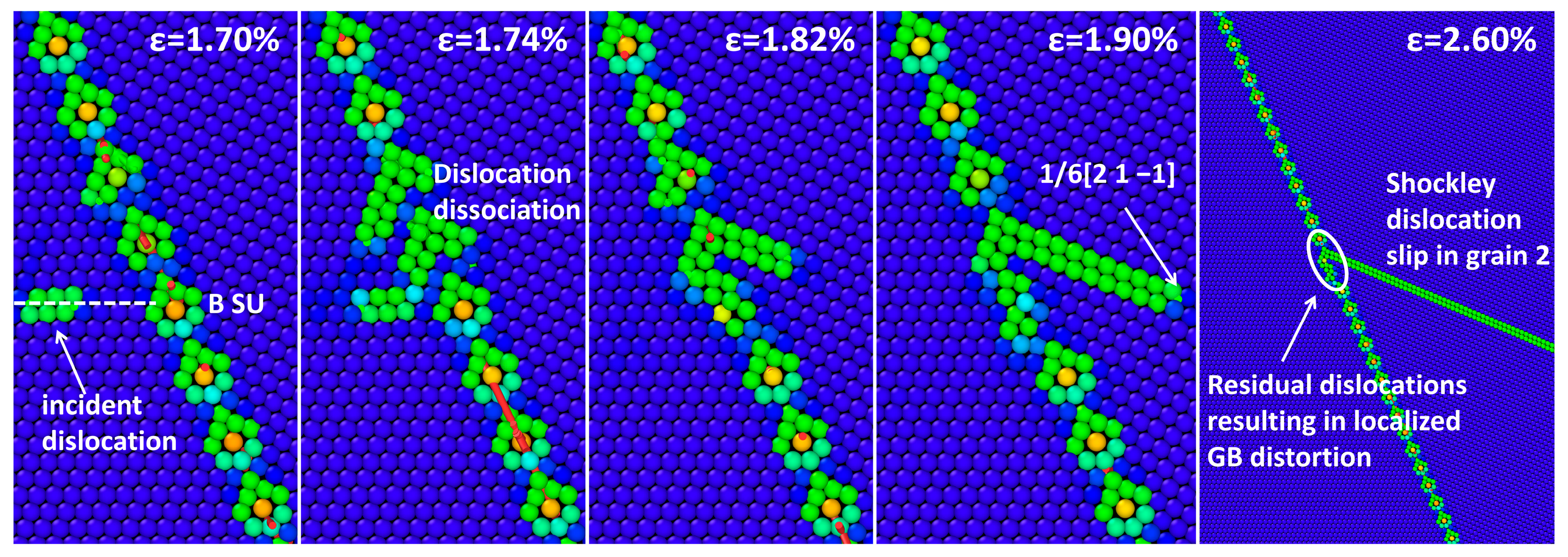
In the Σ51(117)-22.84° model, the GB is composed of alternating A and B SUs, forming an AB-GB configuration. According to the findings of Wang et al. [41], the presence of B SUs inevitably introduces geometrically necessary dislocations (GNDs) within the GB structure. The GB–dislocation interaction process is illustrated in Figure 4. As the interaction mechanisms are nearly identical for impact points located on either A or B SUs, following discussion focuses on the case where the dislocation impinges on a B SU, the interaction process shown in Figure 4.
When the incident dislocation approaches the GB, its stress field induces the decomposition of the dislocation within the B SU near the impact region. The process can be expressed as:
0   0   1 ¯ B     1 6 2 ¯   1 ¯   1 ¯ +   1 6 1   1 ¯   2 ¯ +   1 6 2   1   1 ¯ +   1 6 1 ¯   1   2 ¯
During this interaction, before the incident dislocation reaches the GB plane, it merges with Shockley partial dislocations emitted from two adjacent B SUs. This reaction generates stair-rod (S–R) and Hirth dislocations, which are subsequently absorbed by the GB:
1 6 1   2   1 P + 1 6 2 ¯   1 ¯   1 ¯ 1 6 1 ¯   1   0 S R
1 6 2   1   1 ¯ L + 1 6 2 ¯   1 ¯   1 ¯ 1 3 0   0   1 ¯ H i r t h
Meanwhile, the 1 / 6 2   1   1 ¯ dislocation produced from the decomposition of the B SU, as shown in Equation (2), is transmitted into grain 2 and continues to glide along its slip plane. It is noteworthy that the residual dislocations do not evolve into glissile dislocations at the GB but remain pinned near the impact site, leading to slight normal migration of the local GB segment.
Overall, the Σ51(117)-22.84° GB allows partial dislocation transmission into grain 2 while simultaneously absorbing the residual components. This mechanism can be summarized as follows: as the incident dislocation approaches the GB, its stress field can either induce the nucleation of new dislocations at the GB or trigger the decomposition of existing GB dislocations. The newly generated or decomposed dislocations may transmit into the neighboring grain, while the absorption of the incident dislocation compensates for the Burgers vector loss, restoring local equilibrium within the GB structure. These phenomena reveal the multipath and asymmetric nature of dislocation transmission and absorption in GB structures, providing important insights into the role of GB architecture in governing plastic deformation behavior.

3.2. Σ27(115)-31.59°

According to the research by Wang et al. [42], Σ27(115)-31.59° bi-crystal model exhibit three distinct GB configurations: BCA-GB, CA-GB, and B-GB, as shown in Figure 5. This is primarily governed by the SFE of the material [12].
In this study, the GB–dislocation interactions for all three GB configurations were analyzed. The results indicate that the type of SU at the impact site has only a limited influence on the GB–dislocation interaction process. Therefore, only one representative impact site was selected for each GB configuration to simplify the analysis and highlight the dominant interaction mechanisms.
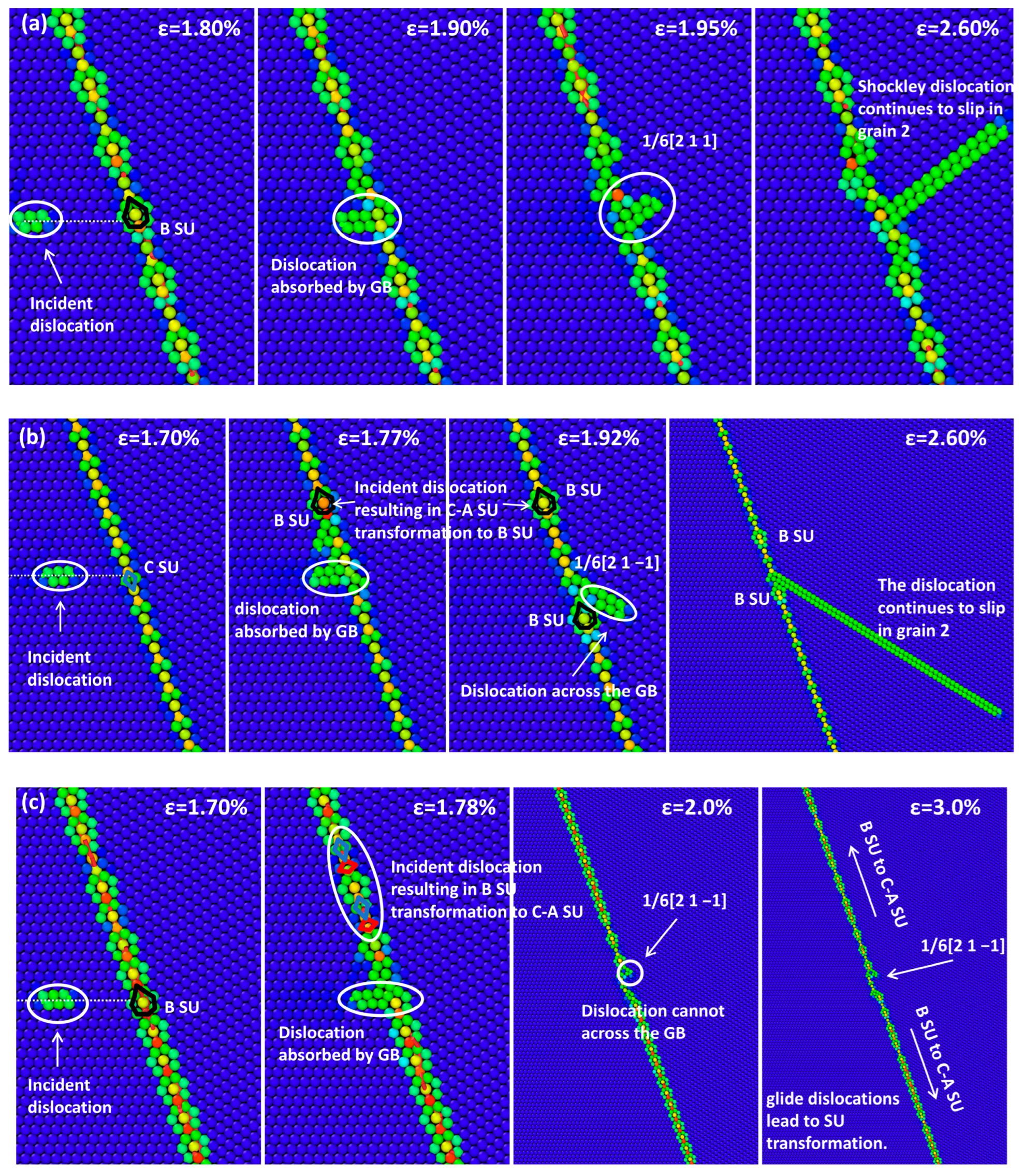
Figure 6a shows the interaction process between the incident dislocation and the BCA-GB configuration, where the impact site is located on B SU. Upon impingement, the Shockley dislocation transmits directly through the grain boundary to grain 2. The residual dislocation remains pinned near the impact region without decomposing into glissile GB dislocations. Consequently, its influence is localized, inducing only slight GB distortion near the impact point without causing any noticeable GB migration.
Figure 6b presents the GB–dislocation interaction process for the CA-GB model, with the impact site located on C SU. It can be observed that the dislocation impact triggers a local transformation of C-A SUs into B SUs near the impact region. This SU conversion can also occur under tensile loading, as reported by Wang et al. [42]. The absorbed incident dislocation subsequently decomposes into two glissile dislocations, according to Bollman’s theory [3] the decomposition can be expressed as:
1 2 1   1   0 1 54 16   11   1 ¯ + 1 54 11   16   1
Afterward, the 1 / 6 2   1   1 ¯ Shockley dislocation nucleates at the GB and glides into grain 2, after which no further SU transformation is observed. Based on the conservation of Burgers vectors, the reaction can be further expressed as:
1 54 16   11   1 ¯ 1 6 2   1   1 ¯ + 1 27 1 ¯   1   4
Figure 6c illustrates the interaction process for the B-GB configuration, where the impact site is located on B SU. Similarly to the CA-GB case, dislocation absorption induces the transformation of B to C-A SUs near the impact site. However, unlike in the CA-GB model, the incident dislocation is not transmitted into grain 2 but remains pinned at the GB, thereby, the accumulated Burgers vector increment cannot be released via dislocation emission, As a result, continuous SU transformation occurs along the GB.
Among the three GB configurations, the BCA-GB exhibits the lowest GB energy [42], while both the CA-GB and B-GB configurations display localized SU transformation phenomena. In the B-GB model, B SUs convert into C-A SUs, whereas in the CA-GB model, the C-A SUs transform into B SUs. Upon completion of these transformations, both GBs locally evolve into the lower-energy BCA-GB configuration, thereby reducing the local GB energy.

3.3. Σ9(114)-38.94°

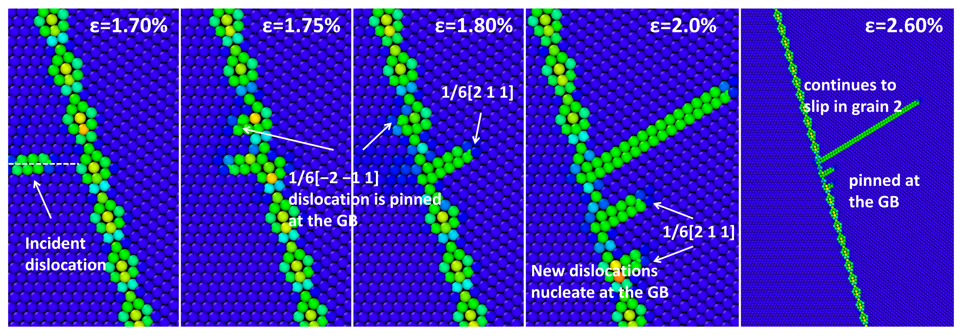
In the Σ9(114)-38.94° bi-crystal Cu model, the GB is composed of B and C SUs. The simulation results indicate that the SU type at the dislocation impact site has only a minor effect on the GB–dislocation interaction process. Therefore, only the case where the impact point is located on a B SU is analyzed here. Figure 7 illustrates the evolution of the interaction process between the GB and the incident dislocation.
After the leading partial dislocation 1 / 6 2   1   1 ¯ impinges on the GB, it is absorbed and induces the formation of a new Shockley dislocation on the adjacent B SU, which subsequently reflects into grain 1. However, this reflected dislocation cannot slip within grain 1 and instead remains pinned at the GB through the intrinsic stacking fault (ISF) facet. Subsequently, the trailing dislocation is absorbed and a new Shockley dislocation forms at the intersection site, transmitting into grain 2 along the 1 ¯   1   1 glide plane. With further increase in applied load, the previously pinned dislocation at the B SU be absorbed, leading to the nucleation of new dislocations that are also transmitted into grain 2. Similarly, the newly nucleated Shockley dislocations remain attached to the B SUs through the ISF facet.
In the models containing B SUs, including Σ51(117)-22.84°, Σ27(115)-31.59° and Σ9(114)-38.94°, the incident dislocation is absorbed by the GB with B-GB configuration, and preventing cross-boundary transmission, whereas in the other models, absorbed dislocations induce Shockley partial transmission into grain 2. Although residual dislocations remain at the GB, their glide is strongly restricted. The simulation results demonstrate that isolated B SUs hinder the in-plane motion of residual dislocations, while continuous B SUs suppress cross-boundary transmission. However, coordinated interactions among SUs of the same type can facilitate limited dislocation slip along the GB plane.

3.4. Σ11(113)-50.48°

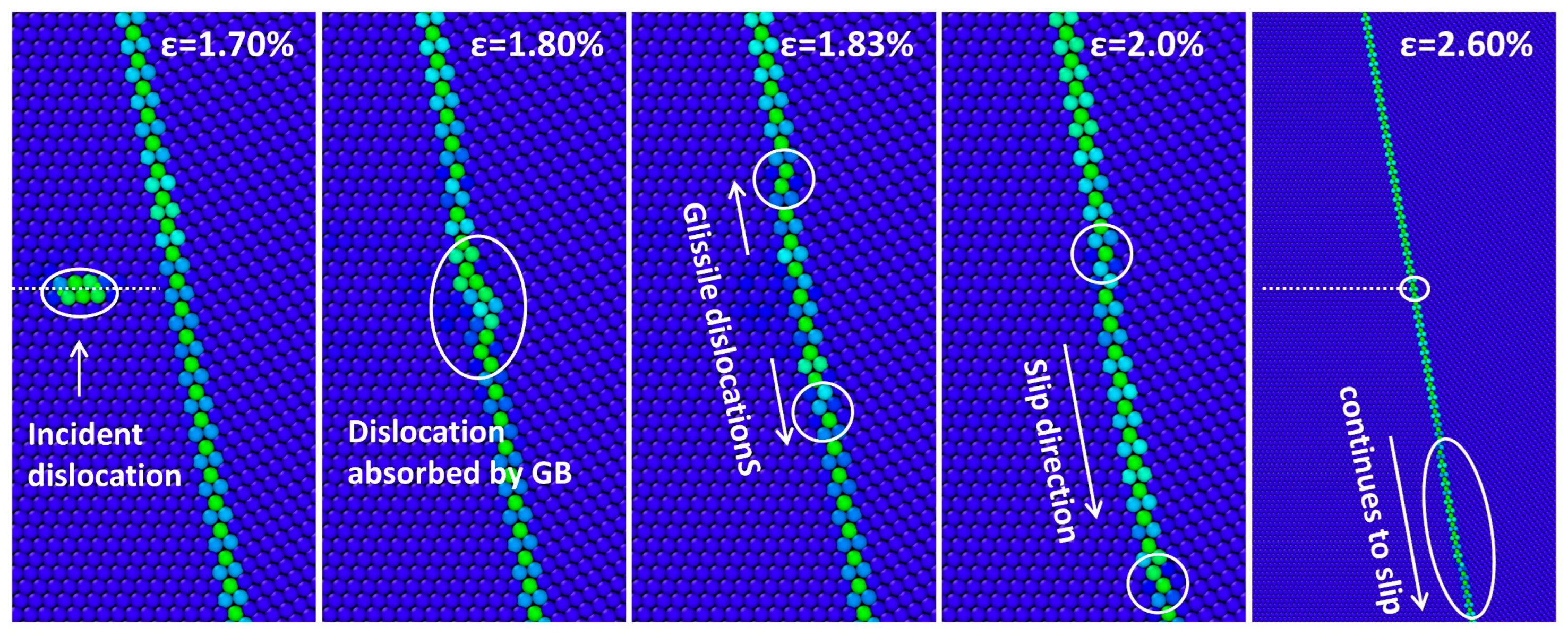
Figure 8 shows the interaction process between the Σ11(113)-50.48° GB and incident dislocation. This GB is composed solely of C SUs, and therefore only one glide plane is considered. After the dislocation is absorbed by the GB, the C SU at the impact site undergoes a local displacement of approximately two atomic layers along the GB normal direction. During this process, no dislocation is transferred to grain 2. A similar phenomenon was observed experimentally by Zhu et al. [43] using TEM during shear deformation of the Σ11 bi-crystal model.
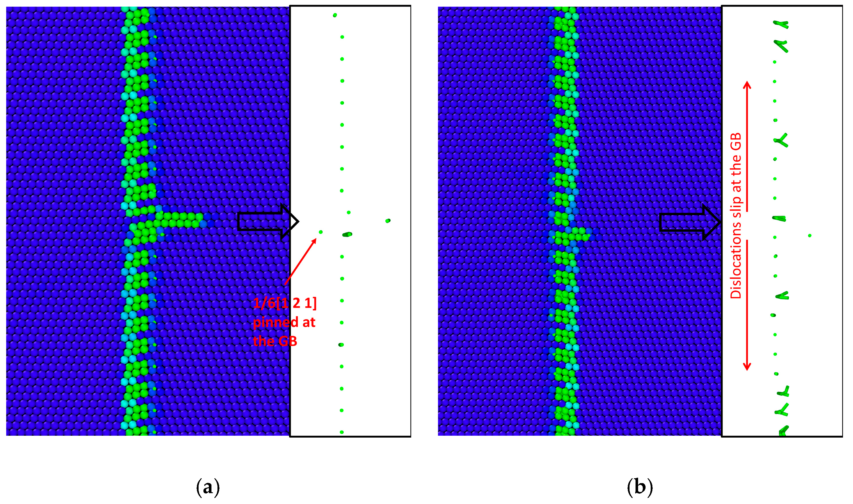
This result indicates that the Σ11(113)-50.48° GB avoids new dislocation nucleation by undergoing local atomic distortion after absorbing dislocations. The absorbed dislocation further decomposes into glissile dislocations in GB, causing atomic-scale migration of the GB segment near the impact region. According to the displacement site compensation (DSC) lattice model [3,44], the dislocation reaction at the GB can be expressed as:
1 2 1   1   0     1 22 7   4   1 ¯   +   1 22 4   7   1
As the applied load increases, the two glissile dislocations slip downward along the GB plane maintaining a spacing of approximately eleven C SUs. No transmitted dislocations into grain 2 are observed during the entire interaction process.
Rae and Smith [45] suggested that GB migration is associated with the motion of GB dislocations. Based on the CSL theory, the GB dislocations responsible for the migration of the Σ11(113)-50.48° boundary may possess Burgers vectors of 1/11<113>, 1/22<332>, 1/22<471> and 1/22<741>. Atomistic simulations of GB migration [46,47] further indicate that the motion of dislocations with Burgers vectors 1/22<471> and 1/22<741> is the dominant mechanism driving Σ11(113) GB migration. This suggests that the Σ11(113)-50.48° GB can accommodate the Burgers vector increment introduced by the incident dislocation through self-migration, thereby preventing the nucleation of Shockley dislocations at the interface.
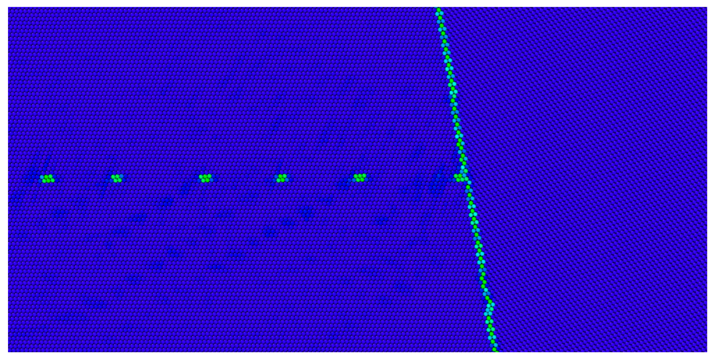
This mechanism allows the Σ11(113)-50.48° GB to absorb a larger number of incident dislocations. To verify this hypothesis, the “dislocation gun” concept proposed by Zhu et al. [48] was employed to simulate the GB’s dislocation absorption capacity. Specifically, the upper and lower regions on the left side of the model shown in Figure 2b were displaced in opposite directions. When the relative displacement between the two regions reached ( 2 α ) / 2 , a full 1 / 2 1   1   0 dislocation nucleated. Continued loading led to repeated dislocation generation and slip toward the GB, shown as Figure 9.
Upon impact, the GB accommodates local strain concentration by allowing the C SU at the impact site to shift slightly along the GB normal, thereby suppressing the nucleation of Shockley dislocations. The absorbed dislocation decomposes into GB glissile dislocations with a Burgers vector of 1/22<471>, which then slips along the GB toward the model boundaries. A similar process occurs upon subsequent dislocation impacts. During the entire sequence, the GB segments continuously migrate in response to dislocation absorption. This behavior demonstrates that GBs composed of continuous C SUs exhibit excellent deformability and dislocation absorption capability. Through the coordinated mechanism among adjacent SUs, the C-GB configuration is provided with greater dislocation accommodation capacity.

3.5. Σ33(225)-58.99°

In the Σ33(225)-58.99° and Σ3(112)-70.53° models, the GBs are composed of C and D SUs, where the D SU extend into the grains in the form of ISF facet. These ISF facets divide the GB into discrete “island” regions. The main distinction between the two GBs lies in the number of C SUs contained within each “island”: in the Σ33(225)-58.99° GB, each “island” region consists of three adjacent C SUs, whereas in the Σ3(112)-70.53° GB, contains only a single C SU.
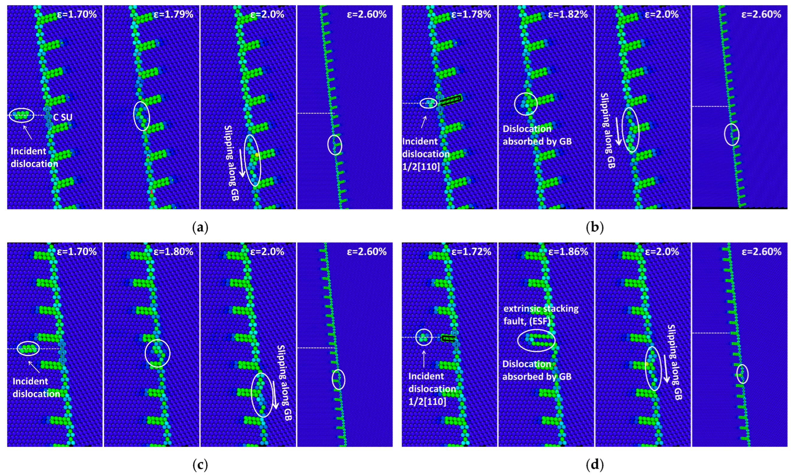
During energy minimization, the ISF facets exhibit random orientations, extending entirely toward either grain 1 or grain 2. This asymmetry leads to locally non-equivalent GB structures on both sides of the interface. Depending on the ISF facet orientation and the SU type at the dislocation impact site, the incident dislocation can interact with the GB along four distinct glide planes, as illustrated in Figure 10.
For the Σ33(225)-58.99° GB, when the interaction occurs along glide planes 1 and 3, shown as Figure 10a,c, the impact site is located on a C SU. Upon impact, the C SUs within the “island” region undergo a pronounced displacement along the GB normal direction, similar to the interaction behavior observed in the Σ11(113)-50.48° GB. The incident dislocation is then absorbed by the GB and dissociates within the interface forming two glissile GB dislocations. These dislocations are able to slip across the ISF facet separated regions and continue migrating along the GB plane. The dissociation reaction can be expressed as:
1 2 1   1   0 1 66 19   14   2 ¯ + 1 66 14   19   2
When the interaction occurs along slip planes 2 or 4, the impact site is located on a D SU. As the incident dislocation approaches the GB, the two separated Shockley partials recombine into a full 1 / 2 1   1   0 dislocation, which is subsequently absorbed by the GB. The absorbed full dislocation then decomposes into GB glissile dislocations that slip along the interface.
In summary, across all four interaction processes, no cross-boundary transmission of the incident dislocation into grain 2 is observed. In each case, the incident dislocation is absorbed by the GB and decomposes into glissile dislocations that slip within the GB plane. The Σ33(225)-58.99° boundary exhibits strong dislocation absorption capability, effectively trapping the incident dislocation and dissipating its Burgers vector through interfacial glide.

3.6. Σ3(112)-70.53°

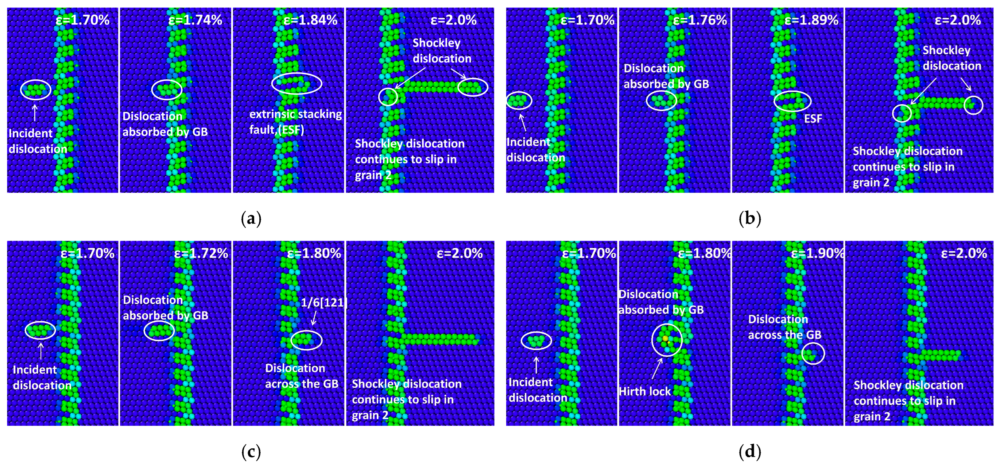
Figure 11 illustrates the process of GB–dislocation interactions under different glide planes in the Σ3(112)-70.53° GB. Unlike the Σ33(225)-58.99° GB, all four cases in the Σ3(112)-70.53° model allow Shockley partial dislocations to transmit across the GB into grain 2, regardless of the orientation of the ISF facet or the impact position of the incoming dislocation.
However, the local interaction mechanisms vary depending on the orientation of the ISF facet. When the ISF facet is oriented toward grain 2, as shown in Figure 11a,b, the Shockley dislocation is transmitted into grain 2, while the residual dislocation at the GB remains pinned near the root of the ISF facet without appreciable interfacial glide, as illustrated in Figure 12a. In contrast, when the ISF facet is oriented toward grain 1, as shown in Figure 11c,d, the incident dislocation first combines with the Shockley dislocation located at the tip of the ISF facet, forming a new composite dislocation, and then dissociates to emit a new Shockley dislocation. Simultaneously, the residual dislocations slip along the GB, inducing slight atomic rearrangements in the local GB structure. As shown in Figure 12b, the dislocation line at the ISF facet transforms from an initially straight configuration into an irregularly curved morphology, reflecting a structural reconstruction of the GB induced by local dislocation slip. This contrast highlights the crucial role of ISF facet orientation in governing the microscopic interaction mechanisms between GBs and dislocations.
C SUs were identified in the Σ11(113)-50.48°, Σ33(225)-58.99°, and Σ3(112)-70.53° GBs. Among them, the Σ11(113)-50.48° GB consists of continuously C SUs, while the Σ33(225)-58.99° and Σ3(112)-70.53° GBs contain discrete “island” regions separated by ISF facets. A comparative analysis of the dislocation interaction behaviors reveals that continuously distributed C SUs effectively absorb incident dislocations, preventing their transmission across the GB. For the discrete-type GBs Σ33(225)-58.99° and Σ3(112)-70.53°, dislocations are absorbed by the GB in the former but are able to transmit across the GB in the latter. Further examination indicates that the ability of dislocations to across the GB is strongly correlated with the number of C SUs within each “island”. When an “island” contains only a single C SU, its normal displacement under the action of the incident dislocation readily induces new dislocation nucleation at the C-D SU interface, facilitating transmission through the GB. In contrast, when multiple C SUs are continuously distributed, the cooperative movement between adjacent SUs leads to the formation of GB glissile dislocations, which slip within the GB plane and dissipates the strain energy of the incident dislocation, thereby suppressing Shockley dislocation transmission. In summary, the ability of a GB to absorb and accommodate incident dislocations is primarily governed by the cooperative motion of C SUs along the GB normal.

4. Conclusions

In this study, MD simulations were employed to investigate the interactions between tilt-[110] Cu GBs containing different SUs and incident dislocations. The main conclusions are as follows:
  • GBs composed of a single type of SU exhibit pronounced dislocation absorption capability. For the Σ27(115)-31.59° with B-GB configuration, the dislocation becomes pinned at the impact site, inducing slight local atomic rearrangement. For the Σ11(113)-50.48° with C-GB configuration, the absorbed dislocation slips along the GB plane as glissile dislocations, leading to atomic-scale sliding behavior within the GB.
  • In the Σ27(115)-31.59° GBs with CA-GB and B-GB configurations, dislocation impact induces SU transformation. Specifically, the SUs in the impact region reconstruct into a local BCA-GB configuration, effectively reducing the interfacial energy and promoting structural optimization of the GB.
  • For GB containing both C SUs and ISF facets, the accommodation of incident dislocations primarily occurs within the “island” regions of C SUs isolated by adjacent ISF facets. When multiple consecutive C SUs are present within such an “island”, cooperative coupling among SUs facilitates efficient dislocation absorption and energy dissipation, thereby suppressing dislocation transmission across the GB.

Author Contributions

Conceptualization, K.W. and Y.X.; methodology, K.W.; software, K.W. and L.X.; validation, W.Z. and J.X.; formal analysis, K.W.; investigation, K.W.; writing—original draft preparation, K.W.; writing—review and editing, K.W. and Y.X.; visualization, K.W.; supervision, W.Z. and J.X. All authors have read and agreed to the published version of the manuscript.

Funding

This research received no external funding.

Data Availability Statement

The original contributions presented in this study are included in the article. Further inquiries can be directed to the corresponding author.

Conflicts of Interest

The authors declare no conflicts of interest.

References

  1. Read, W.T.; Shockley, W. Dislocation Models of Crystal Grain Boundaries. Phys. Rev. 1950, 78, 275–289. [Google Scholar] [CrossRef]
  2. Cottrell, A.H. Theory of dislocations. Prog. Met. Phys. 1953, 4, 205–264. [Google Scholar] [CrossRef]
  3. Bollmann, W. Crystal Defects and Crystalline Interfaces; Springer: Heidelberg, Berlin, 1970. [Google Scholar]
  4. Hirth, J.P. The influence of grain boundaries on mechanical properties. Metall. Trans. 1972, 3, 3047–3067. [Google Scholar] [CrossRef]
  5. de Koning, M.; Kurtz, R.J.; Bulatov, V.V.; Henager, C.H.; Hoagland, R.G.; Cai, W.; Nomura, M. Modeling of dislocation–grain boundary interactions in FCC metals. J. Nucl. Mater. 2003, 323, 281–289. [Google Scholar] [CrossRef]
  6. Spearot, D.E.; Sangid, M.D. Insights on slip transmission at grain boundaries from atomistic simulations. Curr. Opin. Solid State Mater. Sci. 2014, 18, 188–195. [Google Scholar] [CrossRef]
  7. Smith, D.A.; Vitek, V.; Pond, R.C. Computer simulation of symmetrical high angle boundaries in aluminium. Acta Metall. 1977, 25, 475–483. [Google Scholar] [CrossRef]
  8. Ashby, M.F.; Spaepen, F.; Williams, S. The structure of grain boundaries described as a packing of polyhedra. Acta Metall. 1978, 26, 1647–1663. [Google Scholar] [CrossRef]
  9. Pond, R.C.; Smith, D.A.; Vitek, V. A model for grain boundary structure based on random close packing. Scr. Metall. 1978, 12, 699–702. [Google Scholar] [CrossRef]
  10. Sutton, A.P.; Vitek, V. On the structure of tilt grain boundaries in cubic metals I. Symmetrical tilt boundaries. Philos. Trans. R. Soc. London Ser. A Math. Phys. Sci. 1983, 309, 1–36. [Google Scholar] [CrossRef]
  11. Sutton, A.P.; Vitek, V. On the structure of tilt grain boundaries in cubic metals. III. Generalizations of the structural study and implications for the properties of grain boundaries. Philos. Trans. R. Soc. London Ser. A Math. Phys. Sci. 1983, 309, 55–68. [Google Scholar]
  12. Rittner, J.; Seidman, D.N. <110> symmetric tilt grain-boundary structures in fcc metals with low stacking-fault energies. Phys. Rev. B 1996, 54, 6999–7015. [Google Scholar]
  13. Kronberg, M.L.; Wilson, F.H. Secondary Recrystallization in Copper. Trans. Metall. Soc. AIME 1949, 185, 501–514. [Google Scholar] [CrossRef]
  14. Tschopp, M.A.; Spearot, D.E.; McDowell, D.L. Influence of Grain Boundary Structure on Dislocation Nucleation in FCC Metals. In Dislocations in Solids; Hirth, J.P., Ed.; Elsevier: Amsterdam, The Netherlands, 2008; Volume 14, pp. 43–139. [Google Scholar]
  15. Tucker, G.J.; Tschopp, M.A.; McDowell, D.L. Evolution of structure and free volume in symmetric tilt grain boundaries during dislocation nucleation. Acta Mater. 2010, 58, 6464–6473. [Google Scholar] [CrossRef]
  16. Tucker, G.J.; McDowell, D.L. Non-equilibrium grain boundary structure and inelastic deformation using atomistic simulations. Int. J. Plast. 2011, 27, 841–857. [Google Scholar] [CrossRef]
  17. Koning, M.D.; Miller, R.; Bulatov, V.V.; Abraham, F.F. Modelling grain-boundary resistance in intergranular dislocation slip transmission. Philos. Mag. A 2002, 82, 2511–2527. [Google Scholar] [CrossRef]
  18. Lee, T.; Robertson, I.; Birnbaum, H. Prediction of slip transfer mechanisms across grain boundaries. Scr. Metall. 1989, 23, 799–803. [Google Scholar] [CrossRef]
  19. Lee, T.C.; Robertson, I.M.; Birnbaum, H.K. Anomalous slip in an FCC system. Ultramicroscopy 1989, 29, 212–216. [Google Scholar] [CrossRef]
  20. Lee, T.C.; Robertson, I.M.; Birnbaum, H.K. AnIn Situ transmission electron microscope deformation study of the slip transfer mechanisms in metals. Metall. Trans. A 1990, 21, 2437–2447. [Google Scholar] [CrossRef]
  21. Lee, T.C.; Robertson, I.M.; Birnbaum, H.K. TEM in situ deformation study of the interaction of lattice dislocations with grain boundaries in metals. Philos. Mag. A 1990, 62, 131–153. [Google Scholar] [CrossRef]
  22. Dewald, M.P.; Curtin, W.A. Multiscale modelling of dislocation/grain-boundary interactions: I. Edge dislocations impinging on Σ11 (1 1 3) tilt boundary in Al. Model. Simul. Mater. Sci. Eng. 2007, 15, S193–S215. [Google Scholar] [CrossRef]
  23. Dewald, M.P.; Curtin, W.A. Multiscale modelling of dislocation/grain boundary interactions. II. Screw dislocations impinging on tilt boundaries in Al. Philos. Mag. 2007, 87, 4615–4641. [Google Scholar] [CrossRef]
  24. Dewald, M.; Curtin, W.A. Multiscale modeling of dislocation/grain-boundary interactions: III. 60° dislocations impinging on Σ3, Σ9 and Σ11 tilt boundaries in Al. Model. Simul. Mater. Sci. Eng. 2011, 19, 055002. [Google Scholar] [CrossRef]
  25. Shimokawa, T. Asymmetric ability of grain boundaries to generate dislocations under tensile or compressive loadings. Phys. Rev. B 2010, 82, 174122. [Google Scholar] [CrossRef]
  26. Jin, Z.H.; Gumbsch, P.; Ma, E.; Albe, K.; Lu, K.; Hahn, H.; Gleiter, H. The interaction mechanism of screw dislocations with coherent twin boundaries in different face-centred cubic metals. Scr. Mater. 2006, 54, 1163–1168. [Google Scholar] [CrossRef]
  27. Jin, Z.H.; Gumbsch, P.; Albe, K.; Ma, E.; Lu, K.; Gleiter, H.; Hahn, H. Interactions between non-screw lattice dislocations and coherent twin boundaries in face-centered cubic metals. Acta Mater. 2008, 56, 1126–1135. [Google Scholar] [CrossRef]
  28. Plimpton, S. Fast Parallel Algorithms for Short-Range Molecular Dynamics. J. Comput. Phys. 1995, 117, 1–19. [Google Scholar] [CrossRef]
  29. Stukowski, A. Visualization and analysis of atomistic simulation data with OVITO–the Open Visualization Tool. Model. Simul. Mater. Sci. Eng. 2009, 18, 015012. [Google Scholar] [CrossRef]
  30. Mishin, Y.; Mehl, M.J.; Papaconstantopoulos, D.A.; Voter, A.F.; Kress, J.D. Structural stability and lattice defects in copper:Ab initio, tight-binding, and embedded-atom calculations. Phys. Rev. B 2001, 63, 224106. [Google Scholar] [CrossRef]
  31. Carter, C.B.; Ray, I.L.F. On the stacking-fault energies of copper alloys. Philos. Mag. A J. Theor. Exp. Appl. Phys. 1977, 35, 189–200. [Google Scholar] [CrossRef]
  32. Hestenes, M.R.; Stiefel, E. Methods of conjugate gradients for solving linear systems. J. Res. Natl. Bur. Stand. 1952, 49, 409–435. [Google Scholar] [CrossRef]
  33. Tschopp, M.A.; Tucker, G.J.; McDowell, D.L. Structure and free volume of <110> symmetric tilt grain boundaries with the E structural unit. Acta Mater. 2007, 55, 3959–3969. [Google Scholar] [CrossRef]
  34. Tschopp, M.A.; Tucker, G.J.; McDowell, D.L. Atomistic simulations of tension–compression asymmetry in dislocation nucleation for copper grain boundaries. Comput. Mater. Sci. 2008, 44, 351–362. [Google Scholar] [CrossRef]
  35. Hoover, W.G. Canonical dynamics: Equilibrium phase-space distributions. Phys. Rev. A 1985, 31, 1695–1697. [Google Scholar] [CrossRef]
  36. Kelchner, C.L.; Plimpton, S.J.; Hamilton, J.C. Dislocation nucleation and defect structure during surface indentation. Phys. Rev. B 1998, 58, 11085–11088. [Google Scholar] [CrossRef]
  37. Hirel, P. Atomsk: A tool for manipulating and converting atomic data files. Comput. Phys. Commun. 2015, 197, 212–219. [Google Scholar] [CrossRef]
  38. Gao, Y.; Jin, Z. Interactions between lattice dislocation and Lomer-type low-angle grain boundary in nickel. Comput. Mater. Sci. 2017, 138, 225–235. [Google Scholar] [CrossRef]
  39. Stukowski, A.; Albe, K. Extracting dislocations and non-dislocation crystal defects from atomistic simulation data. Model. Simul. Mater. Sci. Eng. 2010, 18, 085001. [Google Scholar] [CrossRef]
  40. Stukowski, A.; Bulatov, V.V.; Arsenlis, A. Automated identification and indexing of dislocations in crystal interfaces. Model. Simul. Mater. Sci. Eng. 2012, 20, 085007. [Google Scholar] [CrossRef]
  41. Wang, K.; Xu, Y.; Zhang, W.; Xu, J. The impact of structural units on the dislocation nucleation of bi-crystal copper grain boundary. Comput. Mater. Sci. 2023, 218, 111900. [Google Scholar] [CrossRef]
  42. Wang, K.; Xu, L.; Zhang, W.; Xu, J.; Xu, Y. Atomistic simulation on the transformation behaviour of structural units at Σ27 tilt grain boundary. Mol. Simul. 2024, 50, 821–835. [Google Scholar] [CrossRef]
  43. Zhu, Q.; Cao, G.; Wang, J.; Deng, C.; Li, J.; Zhang, Z.; Mao, S.X. In situ atomistic observation of disconnection-mediated grain boundary migration. Nat. Commun. 2019, 10, 156. [Google Scholar] [CrossRef]
  44. Ishida, Y.; McLean, M. Burgers vectors of boundary dislocations in ordered grain boundaries of cubic metals. Philos. Mag. A J. Theor. Exp. Appl. Phys. 1973, 27, 1125–1134. [Google Scholar] [CrossRef]
  45. Rae, C.M.F.; Smith, D.A. On the mechanisms of grain boundary migration. Philos. Mag. A 1980, 41, 477–492. [Google Scholar] [CrossRef]
  46. Wan, L.; Wang, S. Shear response of the Σ11, ⟨1 1 0⟩{1 3 1} symmetric tilt grain boundary studied by molecular dynamics. Model. Simul. Mater. Sci. Eng. 2009, 17, 045008. [Google Scholar] [CrossRef]
  47. Zhang, L.; Lu, C.; Tieu, K.; Zhao, X.; Pei, L. The shear response of copper bicrystals with Sigma11 symmetric and asymmetric tilt grain boundaries by molecular dynamics simulation. Nanoscale 2015, 7, 7224–7233. [Google Scholar] [CrossRef]
  48. Zhu, Y.; Li, Z.; Huang, M. Atomistic modeling of the interaction between matrix dislocation and interfacial misfit dislocation networks in Ni-based single crystal superalloy. Comput. Mater. Sci. 2013, 70, 178–186. [Google Scholar] [CrossRef]
Figure 1. Schematic diagram of five GB SUs, where black and white atoms represent (110) and (220) planes, respectively, the line colors are used only to distinguish SU types.
Metals 15 01291 g001
Figure 2. Schematic diagram of the bi-crystal model. Where (a) is a schematic of the model, and (b) is the Σ11(113)-50.48° model after introduced a dislocation.
Metals 15 01291 g002
Figure 3. GB diagram, with atoms colored by the CSP method.
Metals 15 01291 g003
Figure 4. Σ51(117)-22.84° grain boundary–dislocation interaction process.
Metals 15 01291 g004
Figure 5. Schematic diagram of the tilt-[110]-Σ27(115)-31.59° grain boundary configuration and glide plane.
Metals 15 01291 g005
Figure 6. Σ27(115)-31.59° grain boundary–dislocation interaction process, (a) BCA-GB, the intersection location is B SU, (b) CA-GB, the intersection location is C SU, (c) B-GB, the intersection location is B SU.
Metals 15 01291 g006
Figure 7. Σ9(114)-38.94° grain boundary–dislocation interaction process.
Metals 15 01291 g007
Figure 8. Σ11(113)-50.48° grain boundary–dislocation interaction process.
Metals 15 01291 g008
Figure 9. Continuous dislocation emission into Σ11(113)-50.48° grain boundary by means of dislocation gun.
Metals 15 01291 g009
Figure 10. Interaction processes between GBs and dislocations in four cases of the Σ33(225)-58.99° model. Where (a) Glide plane 1, the intersection location is C SU, (b) Glide plane 2, the intersection location is D SU, (c) Glide plane 3, the intersection location is C SU, (d) Glide plane 4, the intersection location is D SU.
Metals 15 01291 g010
Figure 11. Interaction processes between GBs and dislocations in four cases of the Σ3(112)-70.53° model. Where (a) Glide plane 1, the intersection location is C SU, (b) Glide plane 2, the intersection location is D SU, (c) Glide plane 3, the intersection location is C SU, (d) Glide plane 4, the intersection location is D SU.
Metals 15 01291 g011
Figure 12. Dislocation shapes on the grain boundary after Shockley dislocation transport to Grain 2. Where (a) Residual dislocation is pinned on GB, (b) Residual dislocation decompose into GB glissile dislocations.
Metals 15 01291 g012
Table 1. Bi-crystal models and their GB SU configurations.
ModelGB ConfigurationGB PlaneGB PeriodGB Energy ( m J / m 2 )
Σ51(117)-22.84°AB-GB{1 1 7}AB-AB718.62
Σ27(115)-31.59°B-GB{1 1 5}B-B720.92
Σ9(114)-38.94°BC-GB{1 1 4}BC-BC666.21
Σ11(113)-50.48°C-GB{1 1 3}C-C308.92
Σ33(225)-58.99°CCCD-GB{2 2 5}CCCD-CCCD516.21
Σ3(112)-70.53°CD-GB{1 1 2}CD-CD572.81
Disclaimer/Publisher’s Note: The statements, opinions and data contained in all publications are solely those of the individual author(s) and contributor(s) and not of MDPI and/or the editor(s). MDPI and/or the editor(s) disclaim responsibility for any injury to people or property resulting from any ideas, methods, instructions or products referred to in the content.