Abstract
Liquid metal embrittlement (LME) occurs when a normally ductile alloy undergoes brittle fracture in contact with a liquid metal. The mechanisms behind LME remain unclear, and most of the models rely on post mortem analyses. In this work, we overcome this limitation by performing in situ scanning electron microscopy (SEM) notched micro-bending tests on α-brasses exposed to the gallium–indium eutectic (EGaIn) at room temperature, enabling real-time correlation between load–displacement curves and crack evolution during LME. In the Cu-30%Zn alloy, LME was observed only after prior plastic deformation and ductile crack growth, confirming that liquid metal did not influence early plasticity. A two-step experiment further showed that a pre-existing crack in contact with EGaIn, under continued loading, was sufficient to trigger brittle fracture. The Cu-20%Zn alloy displayed alternating ductile and brittle events, with brittle cracks propagating horizontally before arresting in undeformed zones, leading to stepped load–displacement curves. By contrast, pure Cu and Cu-15%Zn showed only ductile fracture despite continuous contact with EGaIn. These results demonstrate that LME in the Cu-Zn/EGaIn system acts during crack propagation rather than initiation. The present in situ SEM methodology provides direct evidence of fracture mechanisms and a framework for future experimental modeling comparisons.
1. Introduction
Liquid Metal Embrittlement (LME) is a phenomenon in which a normally ductile metal or alloy undergoes a significant loss of ductility when exposed to a liquid metal. This phenomenon often results in sudden brittle failure, posing critical risks across various industrial applications, including hot-dip galvanizing, welding, nuclear reactors, and electronic components involving low-melting-point metals [1,2,3].
LME can be broadly classified into two types. Type I LME displays spontaneous grain boundary wetting, where the liquid metal penetrates the grain boundaries without requiring external stress, with some well-known systems, such as Al/Ga [4] and Cu/Bi [5]. In contrast, Type II LME requires a plastic strain during the contact of the solid with the liquid for the embrittlement to occur. The present article focuses on this last type, which is the most common in industrially relevant systems, e.g., Fe/Zn [3] and Fe/Pb-Bi [6,7]. This LME type is highly sensitive to intrinsic material properties (microstructure, hardness, chemical composition) and experimental conditions (temperature, strain rate, oxygen content, stress concentration) [8]. The interplay of these factors makes LME a complex problem, often leading to apparently contradictory results. For instance, it was once assumed that any intermetallic compound formation at the solid–liquid interface would block liquid metal penetration and suppress LME [9]. However, recent studies have disproven this assumption in systems such as Fe/Zn [3] and Cu-Zn/EGaIn (Ga-In eutectic) [10], where intermetallic formation did not prevent LME.
Several models have been proposed to explain LME (see references [3,8] for detailed reviews). However, most of them are based on specific cases of LME (specific solid/liquid metal couples) and rely on post mortem analyses at the macroscopic and microscopic scales, even though the critical mechanisms act at finer scales. Thus, extrapolating these models to other solid/liquid systems to predict LME sensitivity is challenging. The lack of direct observation is a key limitation: mechanisms such as those proposed by Robertson-Glickman, which involve dissolution aided by stress and capillarity [11], or the Lynch model, which invokes bond weakening by liquid adsorption leading to dislocation nucleation and void coalescence [12], remain assumptions. Despite decades of research, no real-time in situ studies have been available to directly capture fracture initiation and crack propagation during LME. Without this, developing a predictive framework to prevent LME or design resistant materials remains difficult.
To address this gap, this work presents the in situ observations of the LME phenomenon using scanning electron microscopy (SEM). A major experimental challenge is that most of the systems presenting LME, such as Fe/Zn or Fe/Pb [1,3], require high testing temperatures. This obstacle can be avoided by studying systems where the embrittling metal is liquid at low temperatures. Nevertheless, many low-melting-point elements present significant drawbacks such as radioactivity (Cs and Fr), short half-life (Fr), violent chemical properties (Cs and Rb), or toxicity (Hg) [13]. Gallium-based alloys overcome these issues, as they are liquid at low temperatures, non-toxic, and, importantly, exhibit low vapor pressure [14,15,16].
In this study, we selected the Ga-In eutectic (EGaIn) alloy because its melting point is below room temperature (unlike pure Ga), and its binary composition reduces chemical complexity compared to ternary systems such as Galinstan (Ga-In-Sn) or other Ga-based alloys. As the solid phase, we chose α-brasses (Cu-Zn alloys with Zn content below 32 wt.%) to investigate LME susceptibility systematically. These alloys provide a simple microstructural system, maintaining a single-phase face-centered cubic (FCC) structure over a broad composition range. Furthermore, the Cu-Zn/EGaIn system has already proven to be an ideal case of LME for studying composition effects at room temperature [10].
Not only are these materials ideal for in situ SEM observation of LME, but Ga-based alloys are increasingly explored for applications where the risk of LME could become a limiting factor for reliability, e.g., their use as anode material alloyed with Cu [17], in soldering applications [18], and in microelectronics [13]. Furthermore, the Cu-Zn/EGaIn couple can be regarded as a model system for studying LME in reactive environments, helping to elucidate mechanisms relevant to other industrially significant systems, such as Fe/Zn [3]. Nevertheless, differences in crystal structure, diffusion kinetics, and intermetallic formation rates must be taken into account, as they limit quantitative extrapolation between these systems.
This work presents a detailed investigation of the LME behavior of α-brasses in contact with liquid EGaIn, utilizing in situ SEM observations to capture both fracture initiation and crack propagation in real time. The methodology developed in this study can be used to enhance the understanding of LME mechanisms and can be extended to other solid/liquid metal systems.
2. Materials and Methods
2.1. Solid and Liquid Materials
α-brasses with Zn contents up to 30 wt.% and as pure Cu were investigated, all of them presenting a single-phase face-centered cubic (FCC) crystal structure. The pure Cu, Cu-15%Zn, and Cu-30%Zn alloys were commercially supplied in sheet form (rolled and annealed) with a thickness of 2 mm. The Cu-20%Zn alloy was not commercially available and was therefore synthesized at the Institut de Chimie et des Matériaux Paris-Est (ICMPE) in France. This was done using an induction furnace to melt high-purity Cu (99.99%) and Zn (99.95%) in a glassy carbon crucible, producing cylindrical ingots with a diameter of 12 mm and a height of 8 mm. The ingots were subsequently cross-rolled to a final thickness of 2 mm.
Table 1 summarizes the different alloy and their corresponding Vickers hardness and average grain size. Hardness was measured using a Buehler hardness testing machine with a load of 4.9 N and a dwell time of 10 s. Grain size was determined by the linear intercept method on optical micrographs of samples etched with an aqueous solution of FeCl3 and HCl.

Table 1.
Hardness and grain size of the investigated α-brasses and pure Cu.
Although hardness in α-brasses is generally expected to increase with Zn content due to solid-solution strengthening, this trend was not strictly observed in the present work. Differences in thermomechanical history between the alloys resulted in variations in grain size and dislocation density that likely overshadowed the intrinsic effect of solid-solution hardening. This effect is particularly evident in the Cu-20%Zn alloy, which exhibits the highest hardness due to the significant deformation introduced during its fabrication process. However, due to the severe deformation, it was not possible to characterize its microstructure, as electron backscatter diffraction (EBSD) scans failed to yield reliable results despite attempts with various metallographic preparations.
The liquid EGaIn was synthesized using 99.99% pure Ga and 99.99% pure In. The experimental procedure involved heating water in a beaker on a hot plate to approximately 80 °C. The Ga container was introduced into the beaker until the Ga melted, and then it was poured into a ceramic crucible. Pure In was progressively added to the crucible until the targeted EGaIn composition was achieved, precisely 24.5 wt.% In. Although the true eutectic composition of the Ga-In binary system lies at 21.4 wt.% In, with a melting temperature of 15.7 °C [19], the alloy containing 24.5 wt.% In is conventionally referred to as eutectic Ga-In (EGaIn) in the literature [13,16]. The mixture underwent continuous agitation until it reached a homogenous liquid state. Further manipulation of the liquid metal was performed at room temperature using a Rainin micropipette.
2.2. In Situ Mechanical Testing
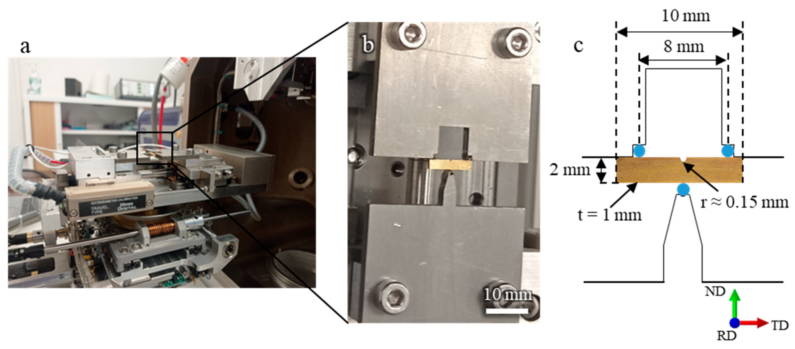
The mechanical test selected for this study was the three-point bending test, which is well-suited for miniaturization as it enables high and localized stresses to be generated within a small and well-defined region of the sample. This configuration simplifies the experimental setup compared with other micromechanical tests, such as tensile testing, where sample preparation and gripping systems are more complex. The introduction of a notch localizes both stress and plastic deformation within a confined region, promoting fracture initiation and enabling the onset of liquid metal embrittlement (LME) to occur in a controlled area. This localization also simplifies in situ SEM observations, as the fracture process can be monitored without the need to adjust the imaging position during the test.
All mechanical tests were conducted at room temperature, taking advantage of the low melting point of EGaIn. The tests were performed using a Deben MICROTEST machine, operating at a displacement rate of 0.4 mm/min. Figure 1 shows an image of the experimental setup and the specimen geometry used for the three-point bending test. ND, RD, and TD refer to the normal, rolling, and transverse directions, respectively. Throughout the experiment, the applied load was recorded as a function of the imposed displacement, allowing the construction of force–displacement curves for each test.
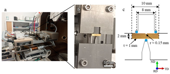
Figure 1.
(a,b) Experimental setup for the in situ SEM observations using a three-point bending test with a Deben MICROTEST device. (c) specimen geometry used for microscale fracture testing.
The samples were cut from the material plates using electrical discharge machining. Before the in situ mechanical testing, one face of each sample was metallographically polished, with the final polishing cycle using diamond paste with a granulometry of ¼ µm. Then, they were etched using an aqueous solution of FeCl3 and HCl to create a slight rugosity that reveals the grain boundaries observed by SEM using secondary electrons.
Direct contact condition between the solid samples and the liquid metal was achieved by using a 1 M HCl aqueous solution to deoxidize the surface of the solid and the liquid metals, as performed elsewhere [20,21]. A drop of the liquid EGaIn was carefully placed in the notch of the sample using a micropipette, a few minutes before the in situ bending tests. Visual confirmation that the liquid EGaIn entered the notch was done with the naked eye before each test. It was important to avoid overflow of the EGaIn on the polished face of the sample so its observation is possible during the test. Preliminary ex situ experiments demonstrated that the degree of embrittlement was the same whether the EGaIn was placed on one face of the sample or solely inside the notch.
The Hitachi SU 5000 SEM (Tokyo, Japan), located in the electron microscopy facility of the Advanced Characterization Platform at the Chevreul Institute, was used for in situ SEM observations during mechanical testing, as well as for post mortem observations. Since the EGaIn is liquid at room temperature and has a low vapor pressure (<1.33 × 10⁻¹⁰ Pa at 300 °C [13]), it was not necessary to make special accommodations for the in situ SEM observations. Videos of the 3-point bending tests were recorded using the secondary electron detector at 30 frames per second. The tests were conducted at an acceleration voltage of 20 keV and a working distance exceeding 20 mm, allowing for low-magnification observations of the entire polished face of the sample. Comparative in situ tests were also performed in the absence of liquid EGaIn. In addition, at least three ex situ tests were conducted for each alloy and condition to verify reproducibility. Because each experiment yields a distinct force–displacement curve directly correlated with the corresponding sequence of microstructural events, no averaging or error bars were applied so as to preserve the one-to-one correspondence between mechanical response and fracture evolution.
For the post mortem observation of the fracture surface, the liquid metal was dissolved in a 1.1 M HNO3 solution. Then, to observe the fracture surface, it was necessary to remove the CuGa2 intermetallic compound that forms at room temperature between Cu and Ga [13,22,23]. This removal was achieved by using a 1 M NaOH solution.
3. Results
3.1. Cu-30%Zn
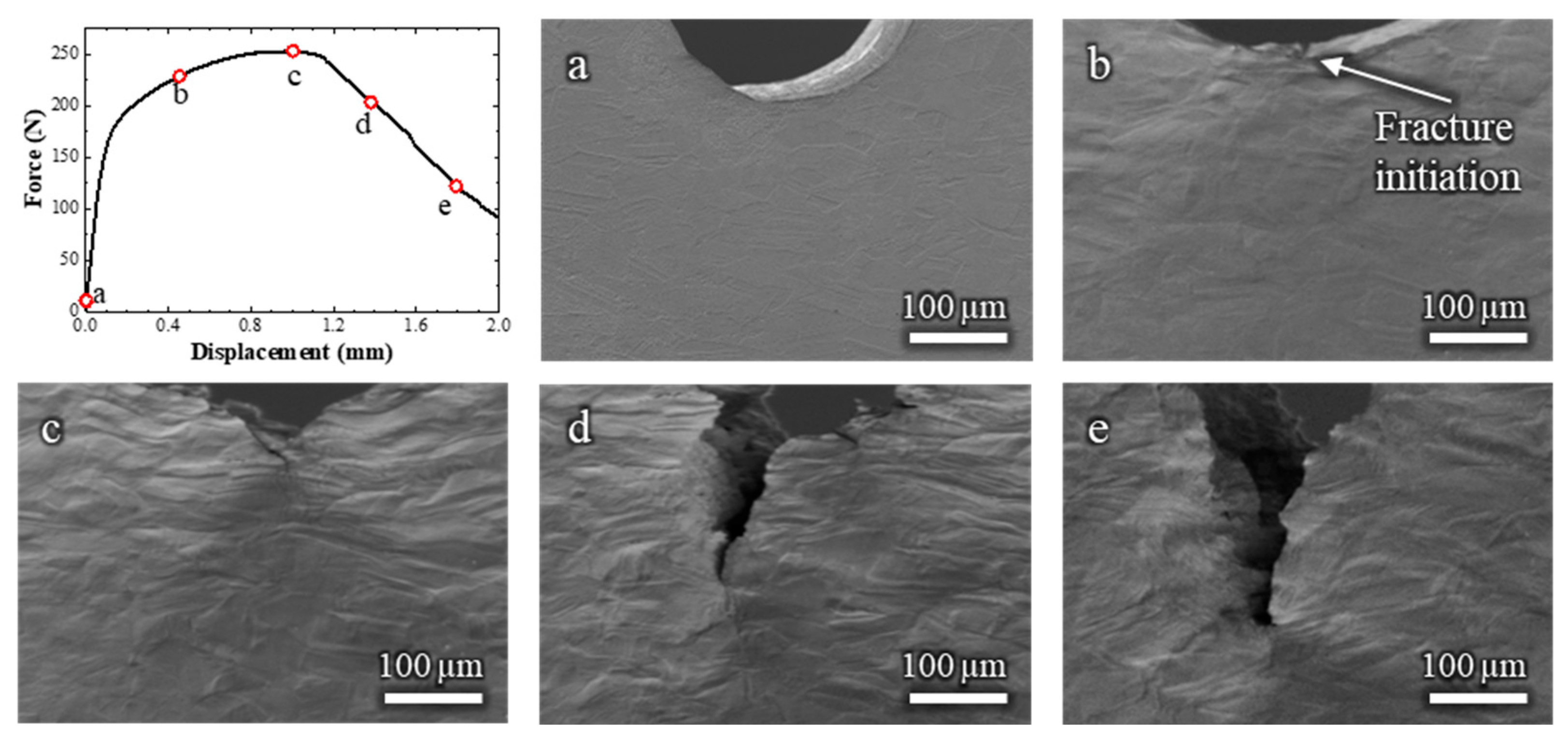
To establish a baseline for comparison, an initial in situ SEM bending test was performed on the Cu-30 wt.% Zn alloy without the presence of liquid EGaIn. The corresponding video is available in Video S1, and selected frames are shown in Figure 2 along with the corresponding force–displacement curve.
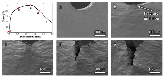
Figure 2.
Load–displacement curve and (a–e) the corresponding in situ SEM observations of a Cu-30%Zn sample tested without liquid EGaIn. The letters relate the micrographs to the exact point of the load–displacement curve.
Figure 2b,c shows that, during plastic deformation, the grains exhibited considerable elongation in the tensile stress direction, which corresponds to the TD direction in Figure 1. Moreover, the force–displacement curve (Figure 2a) shows the strain hardening typical of FCC solid solution alloys. The fracture of the Cu-30%Zn sample initiated at a displacement of 0.45 mm (Figure 2b). At this stage, the sample continues to exhibit a hardening behavior, as the crack is small compared to the volume undergoing plastic deformation. The force only decreases after considerable fracture propagation (Figure 2c), after which the force continuously decreases while the fracture continues its propagation. The sample exhibited entirely ductile behavior throughout the test, characterized by slow fracture propagation and ductility dimples within the fracture; these latter are more clearly visible on the fracture surface in Figure A1 (Appendix A).
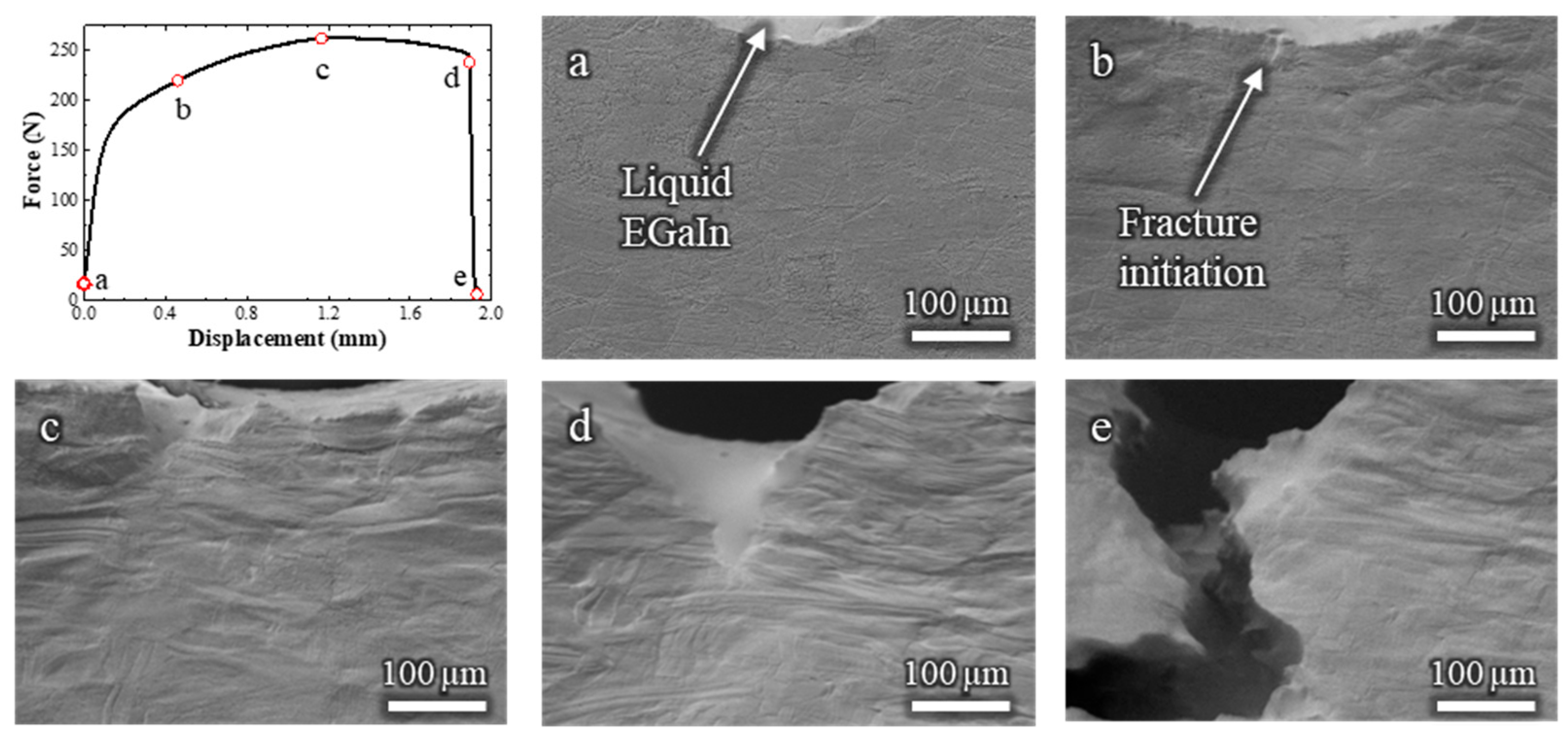
The Cu-30%Zn sample tested in contact with liquid EGaIn (Video S2) exhibited some marked differences compared to the sample tested without liquid metal. The corresponding load–displacement curve and in situ SEM frames are shown in Figure 3. Initially, the mechanical response is similar on both tests, i.e., the curve displays typical strain-hardening behavior, and significant plastic deformation is observed in the grains adjacent to the notch. Fracture initiates at a displacement of 0.46 mm (Figure 3b), which is nearly identical to the initiation point in the absence of EGaIn.
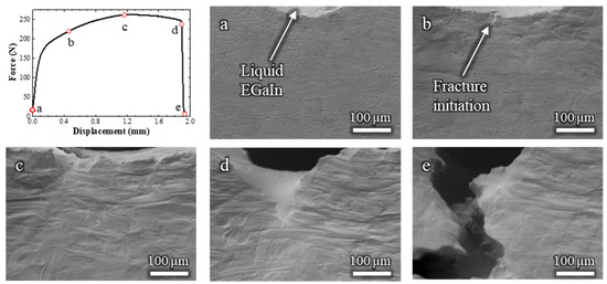
Figure 3.
Load–displacement curve and (a–e) the corresponding in situ SEM observations of a Cu-30%Zn sample tested in contact with liquid EGaIn. The letters relate the micrograph to the exact point of the load–displacement curve.
Immediately after crack initiation, the liquid EGaIn follows the crack opening by capillary, and continues to do so as the crack advances. Between 1.28 and 1.89 mm of displacement (Figure 3c,d), the fracture propagates in a ductile manner, as indicated by the gradual decrease in load and the steady crack propagation. This is followed by a sudden load drop and rapid crack propagation (Figure 3e), consistent with the occurrence of a brittle fracture due to the LME. By the end of the test, no liquid EGaIn remains in the original notch, as it has entirely drawn into the advancing crack, which extends beyond the field of view. Importantly, the mechanical behavior before the onset of the brittle fracture remained unaffected by the presence of the liquid metal. This confirms that embrittlement occurred only during the crack propagation stage, not during the initial plastic deformation.
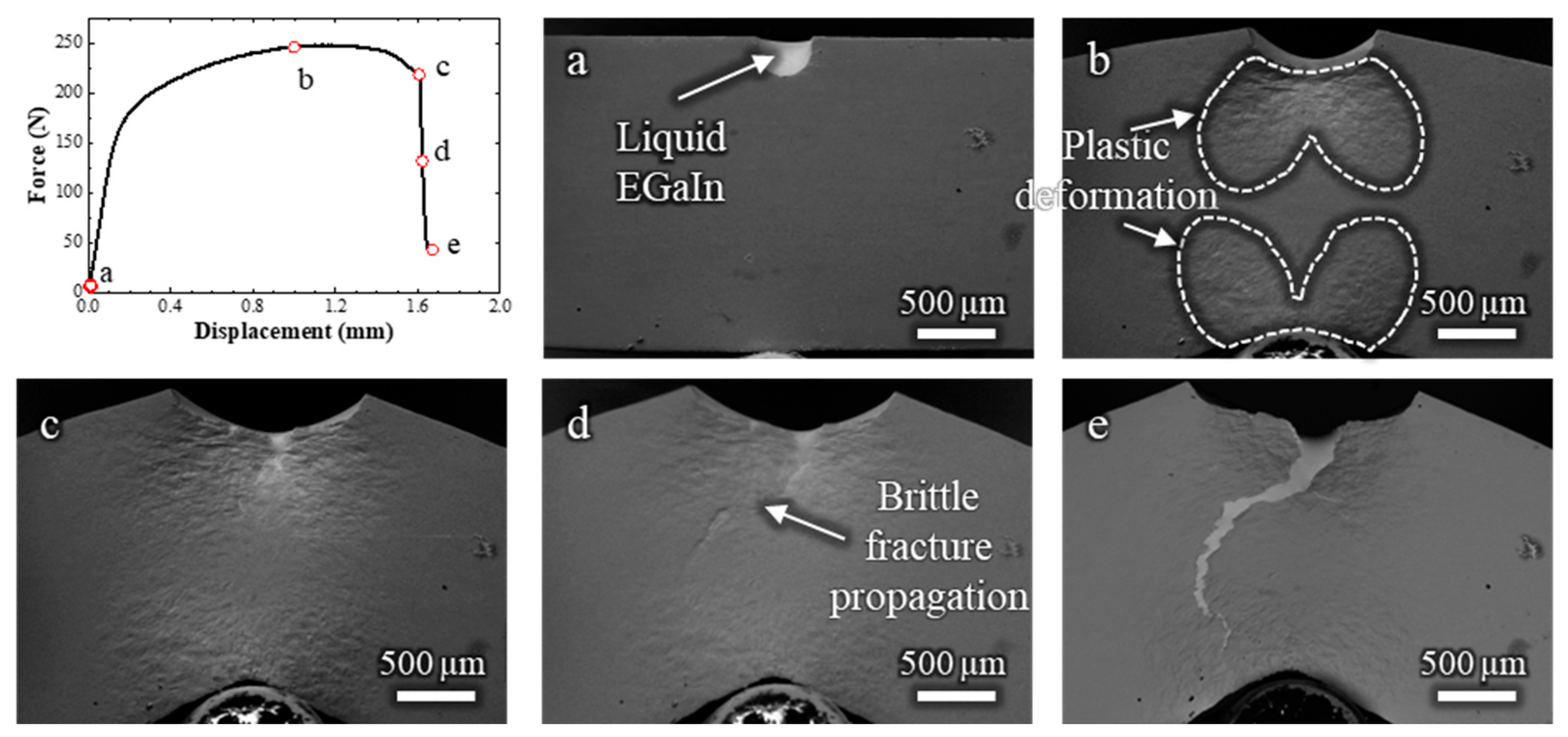
To correlate the crack propagation path with the strain distribution in the sample, another in situ SEM test was carried out at low magnification, allowing observation of the entire specimen (Video S3 and Figure 4). The crack initiation is estimated to occur at a displacement of around 1 mm (Figure 4b); however, the exact frame of fracture initiation could not be clearly identified and may have occurred slightly earlier. During the bending test, the zones that undergo plastic deformation are manifest on the surface (indicated in Figure 4b), and follow the expected distribution pattern of plastic strain for a bending test with these dimensions [10].
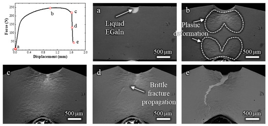
Figure 4.
Load–displacement curve and (a–e) corresponding low-magnification in situ SEM observations of a Cu-30%Zn sample tested in contact with liquid EGaIn. The letters correlate each micrograph with the respective point on the load–displacement curve.
The plastic deformation zone continued to develop even after the ductile fracture had propagated, as shown in Figure 4c, which corresponds to the frame just before the sudden force drop. After this drop, the brittle fracture propagated rapidly across the plastically deformed zone, reaching the opposite side of the specimen at an estimated crack velocity of 0.7 mm/s, highlighting the rapid failure characteristic of LME. The overall fracture behavior in this test is consistent with that shown in Figure 3, but with the added advantage of capturing the rapid propagation of the brittle crack across the entire sample. The slightly lower displacement at failure compared to the test in Figure 3 is attributed to statistical variation inherent to the LME phenomenon.
In the samples that exhibited LME, the rapid brittle fracture was consistently preceded by a slow ductile crack. These fracture modes were confirmed through fractographic analysis; see Figure A2 (Appendix A). To investigate whether ductile fracture in contact with liquid EGaIn is a necessary condition for LME to occur, an additional in situ SEM test was conducted in two steps (Videos S4a and S4b, Figure 5).
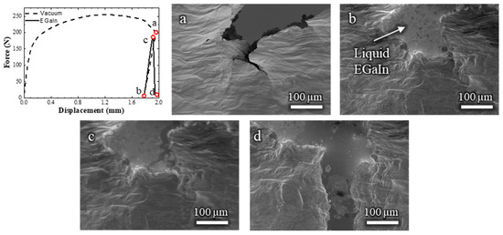
Figure 5.
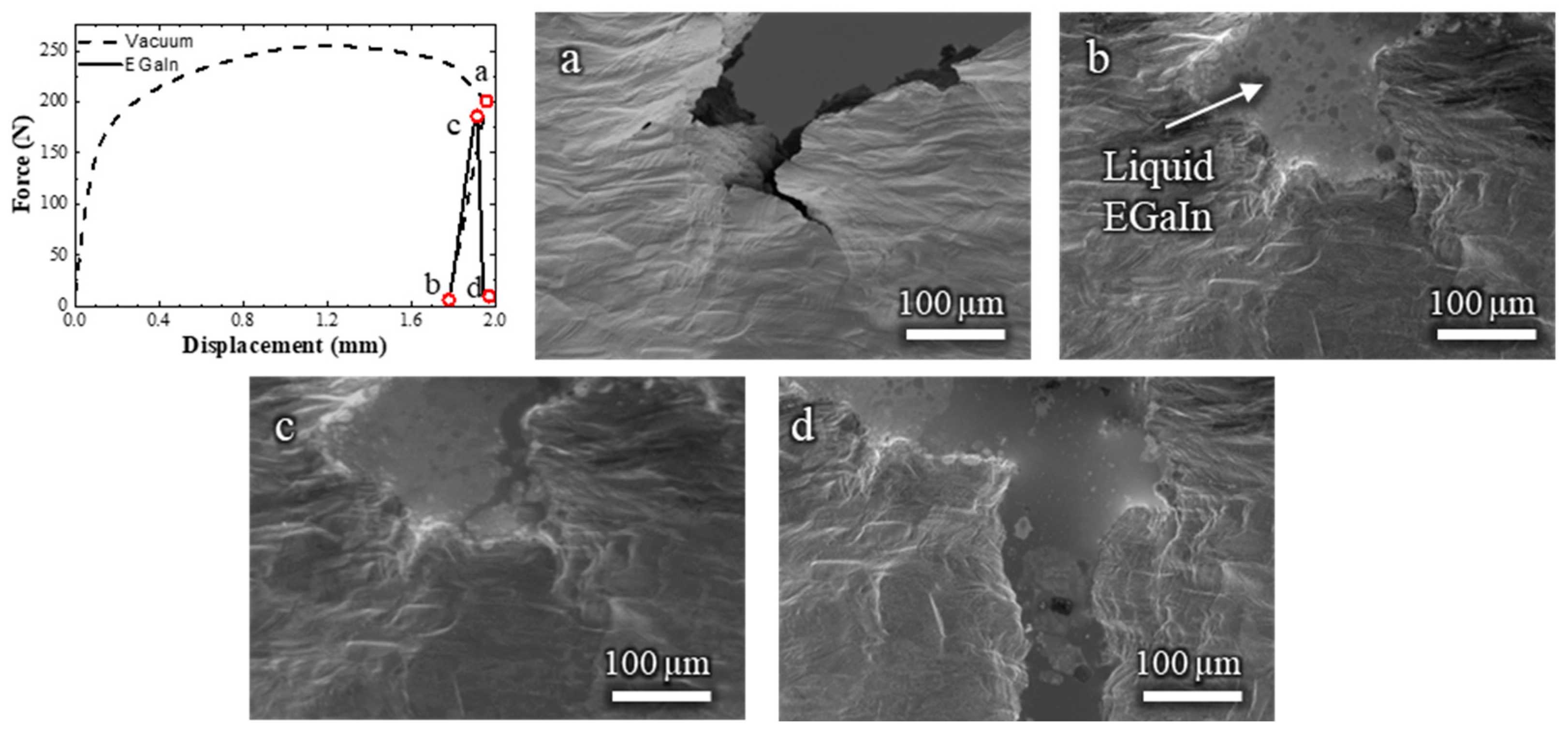
Load–displacement curve and (a–d) the corresponding in situ SEM observations of a Cu-30%Zn sample tested in two steps: first, a pre-crack formed in the absence of liquid EGaIn, followed by further loading after EGaIn was introduced. The letters correspond to the SEM frames at specific points along the load–displacement curve.
In the first step, the sample was tested without liquid EGaIn up to a displacement of 1.958 mm (Figure 5a), which is slightly beyond the onset of the brittle fracture observed in Figure 3d. The sample was then discharged and removed from the setup. The crack was filled with liquid EGaIn, taking care to avoid overflow, and the sample was reintroduced into the setup (Figure 5b). The sample was then mechanically tested again. During the second loading in contact with EGaIn, once the material entered the plastic regime, at a displacement of 1.913 mm, it exhibited no further plastic deformation or ductile crack propagation. Instead, a brittle fracture occurred immediately, suggesting that the presence of a pre-existing crack in contact with the liquid metal is sufficient to trigger LME, even if this pre-existing crack was developed in the absence of liquid EGaIn.
Overall, these observations demonstrate that the presence of liquid EGaIn alone is insufficient to initiate brittle fracture. Instead, a pre-existing crack combined with continued mechanical loading is required to trigger the LME phenomenon. This supports the conclusion that, in the Cu-30%Zn/EGaIn system, embrittlement occurs during crack propagation rather than crack initiation, and is governed by both the mechanical state of the material and the availability of liquid metal at the crack tip.
3.2. Cu-20%Zn
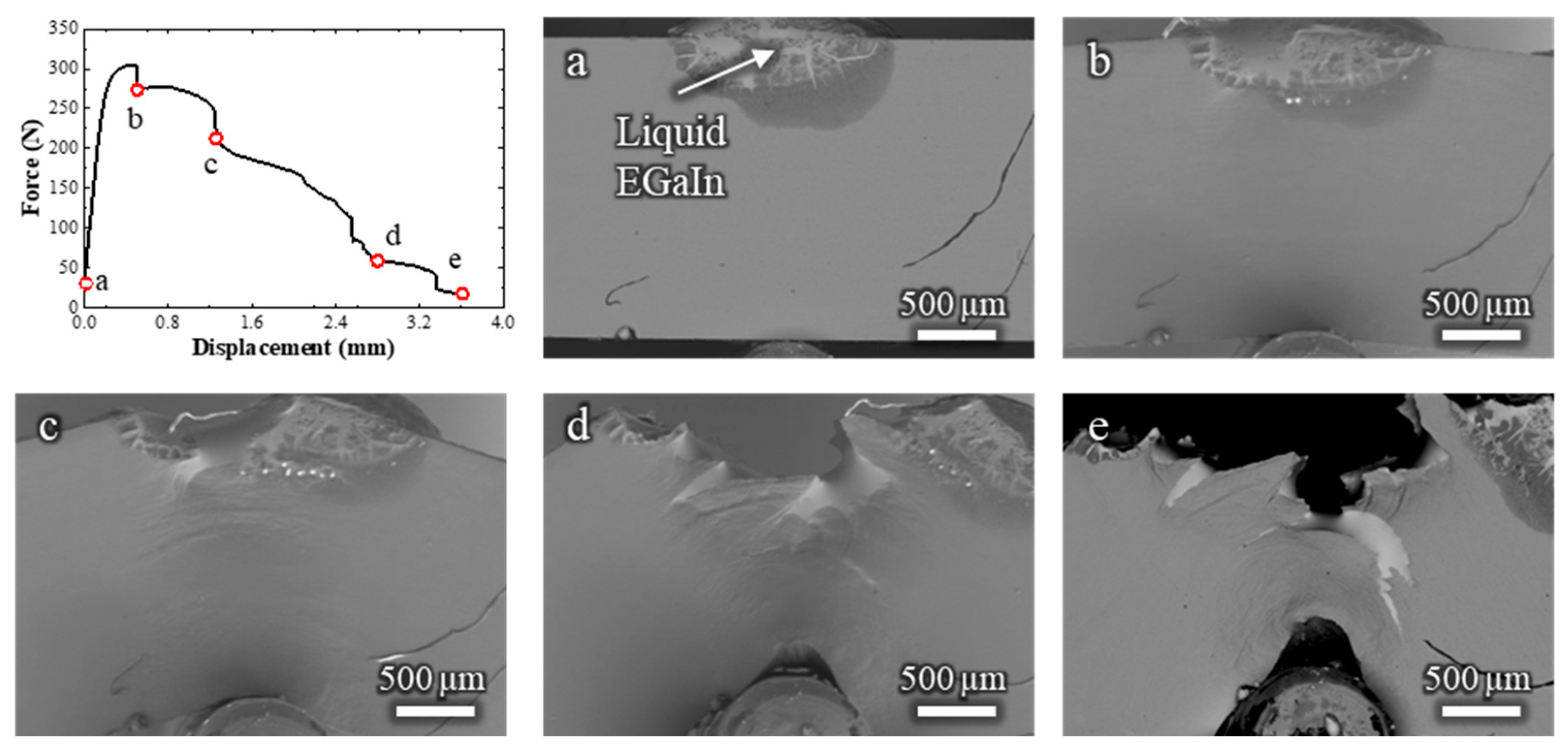
Following the analysis of Cu-30%Zn, additional in situ SEM testing was performed on the Cu-20 wt.% Zn alloy to examine how the Zn content and the microstructure influence the LME. Figure 6 presents the load–displacement curve obtained from this test (Video S5). The curve exhibits a characteristic stepped profile, featuring repeated sudden load drops separated by gradual force decreases. This behavior reflects an alternating sequence of fracture modes: ductile fractures, which propagate slowly, and brittle fractures, which propagate rapidly. These events can be directly correlated with the SEM observations shown in Figure 6a–e. The nature of each fracture mode was further confirmed by fractographic analysis; see Figure A2 (Appendix A).
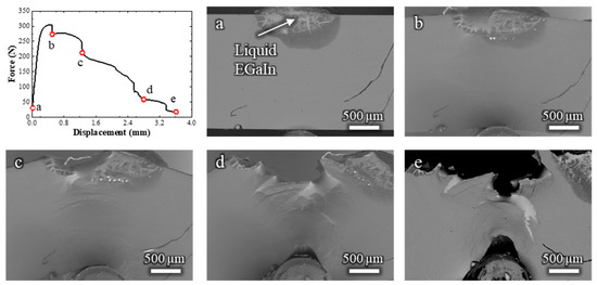
Figure 6.
Load–displacement curve and (a–e) the corresponding low-magnification in situ SEM observations of a Cu-20%Zn sample tested in contact with liquid EGaIn. The letters relate the micrographs to specific points along the load–displacement curve.
To interpret this fracture behavior, it is important to consider the microstructure of the Cu-20%Zn alloy. Due to the fabrication process described in the previous section, the grains are highly elongated along both the rolling direction (RD) and the transverse direction (TD). These directions are indicated in Figure 1 for reference. Given this anisotropic grain structure and the intergranular nature of brittle fracture in this system, the brittle cracks propagate horizontally. These cracks are typically arrested after short distances, as they propagate away from the center of the specimen and reach regions under insufficient plastic strain to sustain further crack propagation. When this occurs, a new fracture initiates, initiating in a ductile mode before transitioning once again into a brittle crack.
This cyclic alternation between ductile and brittle fracture modes continues until the specimen fails, resulting in the stepped profile observed in the load–displacement curve in Figure 6. Throughout the test, the liquid EGaIn is consistently available at the crack tip, maintaining continuous contact with the freshly exposed fracture surfaces. Therefore, the intermittent occurrence of ductile fractures cannot be attributed to the depletion of the liquid metal.
These observations highlight the critical role of microstructural state in controlling LME susceptibility and the ductile-to-brittle transition, which can prevail over the compositional effect of Zn under the tested conditions.
3.3. Cu-15%Zn and Cu
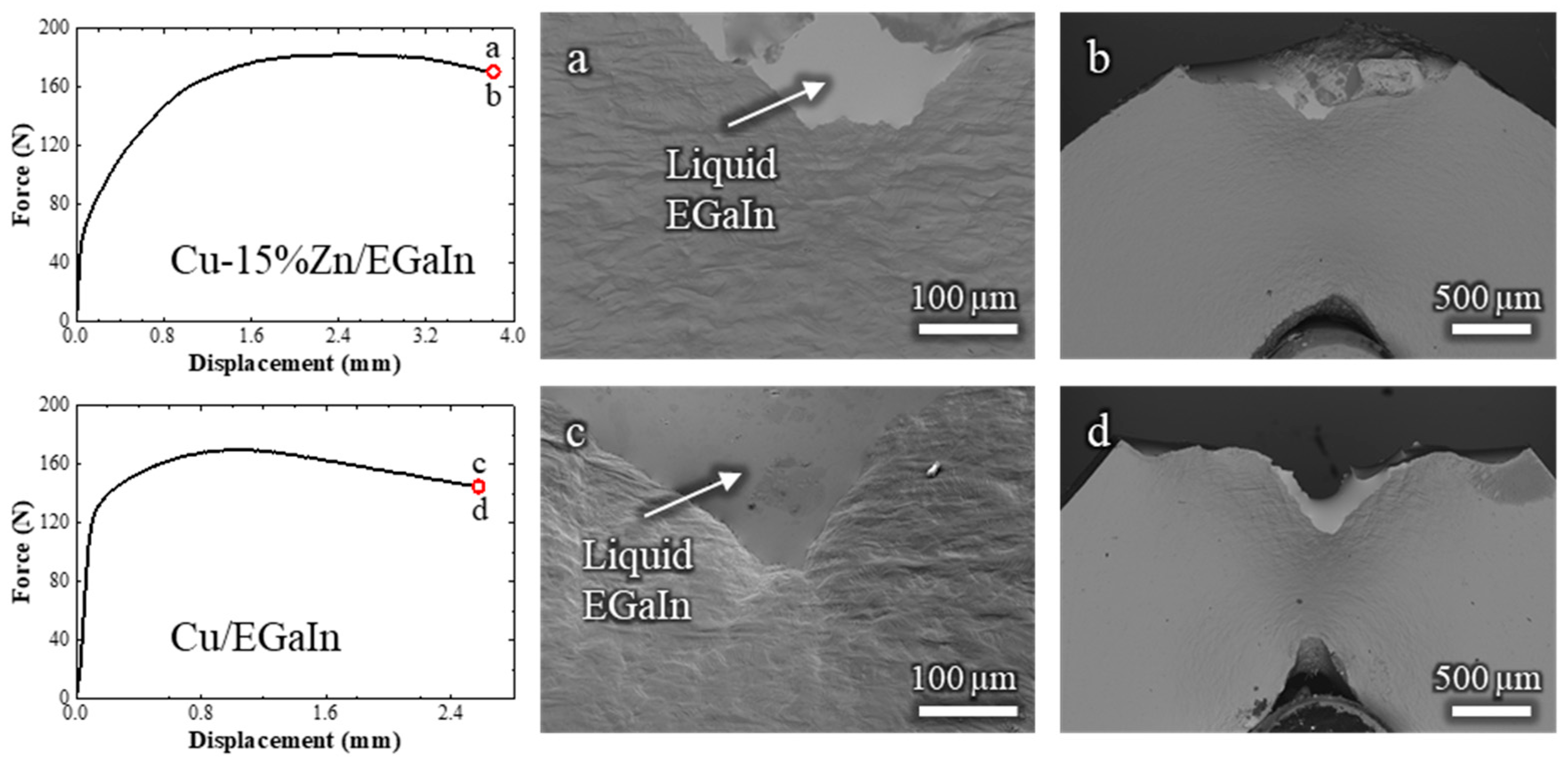
To further assess the influence of Zn content on susceptibility to LME, additional in situ SEM tests were conducted on Cu-15 wt.% Zn and pure Cu. The results are shown in Figure 7 (Videos S6 and S7, respectively). Neither material exhibited any signs of LME when exposed to liquid EGaIn. The corresponding load–displacement curves show a monotonic increase in force during plastic deformation, followed by a gradual decrease, characteristic of stable ductile cracking. Throughout the tests, the liquid EGaIn consistently followed the crack path, confirming that perfect wetting was maintained and that the absence of LME cannot be attributed to a lack of liquid–solid contact.
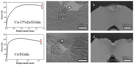
Figure 7.
Load–displacement curves of Cu-15%Zn and pure Cu samples tested in contact with liquid EGaIn, accompanied by corresponding in situ SEM observations at the final stage of loading: (a,b) for Cu-15%Zn and (c,d) for pure Cu.
Furthermore, the cracks propagated over relatively long distances, approximately 0.5 mm in Cu-15%Zn and 1 mm in pure Cu, making it unlikely that the ductile fracture was underdeveloped for LME to be triggered. This is particularly evident when comparing to the Cu-30%Zn and Cu-20%Zn behavior, where LME occurred after ≈0.2 mm of ductile crack propagation. The fracture surfaces of both Cu-15%Zn and pure Cu exhibited only ductile failure features, Figure A3 (Appendix A), and their characteristics do not differ from homologous samples tested in air. These results indicate that, under the conditions tested, Cu-15%Zn and pure Cu are resistant to LME by EGaIn, in contrast to Cu-30%Zn and Cu-20%Zn.
4. Discussion
4.1. Mechanisms of Embrittlement
The in situ SEM observations presented in this study clarify when and how liquid metal embrittlement (LME) manifests in α-brasses in contact with the Ga-In eutectic (EGaIn) alloy. A central result is that early plasticity is not affected by the presence of the liquid metal: before crack initiation, neither the load–displacement response nor the observable deformation activity differs from that in tests without EGaIn. The embrittling influence appeared only after a crack had initiated and began to propagate.
Across all samples that exhibited LME, slow ductile crack propagation consistently preceded rapid brittle fracture. During this process, the liquid metal infiltrated the opening crack by capillary action, maintaining continuous contact with the crack tip throughout propagation. The consistent occurrence of a brittle event following a ductile stage strongly suggests that LME in this system is governed by a propagation-controlled mechanism, rather than by processes active during initial crack initiation.
A two-step experiment further demonstrated that when a pre-crack was created in the absence of liquid metal and then exposed to liquid EGaIn, subsequent loading resulted in an immediate brittle fracture, accompanied by minimal additional plastic deformation. Thus, a pre-strained condition, coupled with a geometric stress concentrator and continued loading, is sufficient to trigger LME once the crack faces are wetted, even if the precursor crack formed in the absence of liquid metal. These observations agree with the model proposed in a previous work for the embrittlement of α-brasses in contact with the liquid EGaIn [10].
The lack of any impact of liquid EGaIn on early plasticity contrasts with models that state adsorption-induced bond weakening to facilitate dislocation nucleation and slip localization before cracking [8,12]. In a reactive couple such as Cu-Zn/EGaIn, interfacial processes, including the formation of the CuGa2 intermetallic and the dissolution of Cu and Zn into the liquid, may limit sustained adsorption at active deformation sites, thereby suppressing any measurable macroscopic effect of the liquid EGaIn before crack formation. This system-specific reactivity may explain the absence of an initiation-stage mechanical effect despite the strong embrittlement observed at the propagation stage.
4.2. Effect of Microstructure and Composition
In the α-brasses studied, susceptibility to LME depends strongly on composition and microstructure. In Cu-20%Zn, anisotropy induced by rolling, together with the intergranular propagation mode of the brittle cracks, produced characteristic fracture paths. Preceded by a short ductile crack segment, the first brittle crack propagates in the transversal direction (TD). The brittle front then arrests upon entering regions with low plastic strain, after which a new short ductile segment forms, and the cycle restarts. This alternation between slow ductile and rapid brittle episodes produces a characteristic stepped load–displacement response.
By contrast, pure Cu and Cu-15%Zn showed no signs of LME: cracks propagated stably following a ductile mode over long distances, despite continuous liquid contact along the crack path. The absence of embrittlement in these alloys cannot be attributed to poor wetting or insufficient liquid availability, highlighting the decisive role of alloy chemistry and microstructural state in enabling LME by EGaIn.
Hardness and plastic zone size also play an important role in LME susceptibility. In α-brasses, increasing Zn content enhances solid-solution hardening; thus, harder alloys such as Cu-30%Zn and Cu-25%Zn, which exhibited clear embrittlement, develop smaller plastic zones at the crack tip. This limits the extent of stable ductile growth and creates conditions favorable for brittle crack propagation in the presence of EGaIn. Conversely, softer alloys such as Cu-15%Zn and pure Cu sustain more extensive plastic deformation, which can relax local stresses and thereby prevent the transition to brittle fracture, even though the liquid metal continuously wets the crack surfaces.
Crucially, these trends could only be revealed through real-time observation of cracking events, which allowed microstructural and mechanical factors to be unambiguously linked to LME susceptibility.
4.3. Methodological Discussion
The complex interplay between stress, plasticity, and liquid metal contact can only be captured through in situ experimentation. Traditional post mortem analysis would fail to distinguish between fractures initiated by ductile mechanisms and those suddenly accelerated by LME. A distinctive feature of this work is that the chosen liquid metal enables in situ SEM observation under vacuum: the low melting point and vapor pressure of EGaIn make it possible to visualize, in one experiment, the onset of ductile cracking, the arrival of the liquid at the crack tip by capillarity, and the subsequent transition to fast brittle propagation.
This combination is uncommon in classical LME systems, which often demand elevated temperatures, e.g., Fe/Zn [3], or for liquid metals that pose practical constraints for in situ electron microscopy, such as toxicity or high vapor pressure, e.g., Hg [13]. Although the Cu-Zn/EGaIn system differs from these cases in several respects; its face-centered cubic (FCC) crystal structure compared with the body-centered cubic (BCC) structure of Fe, its slower diffusion kinetics due to the low temperature [3,24], and its lower intermetallic growth rate [3,23]; it nevertheless provides a model system for investigating the fundamental sequence of events governing LME in reactive solid–liquid metal systems under controlled conditions.
Future work could extend this approach to in situ TEM nanoscale mechanical testing, enabling direct observation of adsorption or dissolution phenomena at the crack tip during the ductile-to-brittle transition.
5. Conclusions
This study successfully demonstrated the use of in situ SEM observations to investigate the liquid metal embrittlement (LME) of α-brasses exposed to the Ga-In eutectic (EGaIn), providing insights inaccessible through conventional post mortem analysis.
In the Cu-30%Zn alloy, LME was observed only after substantial plastic deformation and the initiation of a ductile crack, confirming that the embrittlement mechanism does not affect early plasticity. Brittle fracture consistently followed the initial ductile propagation stage. Furthermore, LME also occurred when a pre-crack was introduced in the absence of liquid metal and the sample was later tested in contact with EGaIn, highlighting that the mechanical conditions at the crack tip are critical for embrittlement. Throughout all tests, EGaIn maintained contact with the fracture surfaces via capillary, and no evidence was found that intermetallic formation suppressed LME.
The in situ approach revealed a particular fracture pattern in the Cu-20%Zn alloy, characterized by alternating ductile and brittle events. The brittle crack propagated horizontally along the rolling direction until reaching regions with insufficient plasticity, after which it arrested, and a ductile fracture initiated. This cyclic behavior resulted in stepped force–displacement curves and represents a rare case of brittle crack arrest under LME conditions. This is strongly linked to the heavily deformed and anisotropic microstructure of the Cu-20%Zn alloy, rather than to its Zn content, accentuating the influence of microstructural state on LME susceptibility.
In contrast, pure Cu and Cu-15%Zn exhibited no signs of LME despite continuous liquid metal contact with propagating cracks. This demonstrates that the absence of embrittlement is not due to poor wetting but rather to compositional or microstructural resistance to crack-tip weakening by EGaIn.
Overall, these findings highlight the value of in situ testing for capturing the complex interplay between alloy composition, plasticity, and liquid metal interactions during LME. They also establish a solid foundation for future quantitative comparisons with multiscale modeling approaches, aimed at advancing predictive understanding of LME, notably in reactive systems.
Supplementary Materials
The following supporting information can be downloaded at: https://zenodo.org/records/17108600 (12 September 2025). Video S1: Cu30Zn-Vacuum; Video S2: Cu30Zn-EGaIn; Video S3: Cu30Zn-EGaIn_low-Zoom; Video S4a: Cu30Zn-Vacuum_pre-crack; Video S4b: Cu30Zn--EGaIn_post-crack; Video S5: Cu20Zn-EGaIn; Video S6: Cu15Zn-EGaIn; Video S7: Cu-EGaIn.
Author Contributions
M.E.: writing—original draft preparation, investigation, methodology; I.P.S.: writing—review and editing, resources, supervision, funding acquisition; A.F.: methodology, writing—review and editing. All authors have read and agreed to the published version of the manuscript.
Funding
This work was financed by the French National Research Agency (ANR) under the project ANR GauguIn (N° ANR-18-CE08-0009-01) and the CNRS and Lille University institutions.
Data Availability Statement
The original contributions presented in this study are included in the article/Supplementary Materials. Further inquiries can be directed to the corresponding authors.
Acknowledgments
The authors thank the Chevreul Institute for its help in the development of this work through the ARCHI-CM project supported by the “Ministère de l’Enseignement Supérieur de la Recherche et de l’Innovation”, the region “Hauts-de-France”, the ERDF program of the European Union and the “Métropole Européenne de Lille”. The authors thank Loïc Perriere and the Institut de Chimie et des Matériaux Paris-Est (ICMPE) for elaborating the Cu-20wt.%Zn alloy.
Conflicts of Interest
The authors declare no conflicts of interest.
Abbreviations
The following abbreviations are used in this manuscript:
| LME | Liquid Metal Embrittlement |
| SEM | Scanning Electron Microscope |
| EGaIn | Gallium-Indium Eutectic |
| FCC | Face-Centered Cubic |
| ND | Normal Direction |
| RD | Rolling Direction |
| TD | Transverse Direction |
| BCC | Body-Centered cubic |
Appendix A. Fractographic Observations
The fractographic analysis of the Cu-30%Zn sample tested without liquid EGaIn (Figure A1a,b) reveals a fully ductile fracture surface, characterized by well-defined dimples consistent with the expected behavior of this alloy. In contrast, the sample tested in contact with liquid EGaIn exhibits a markedly different fracture morphology (Figure A1c–e). While a small region near the notch still displays ductile features, most of the fracture surface is dominated by brittle, intergranular features. This abrupt transition from ductile to brittle fracture strongly indicates the occurrence of liquid metal embrittlement (LME) induced by EGaIn.
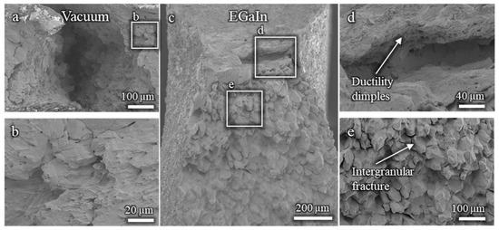
Figure A1.
Fractographies of Cu-30%Zn samples tested using three-point bending: (a,b) without liquid EGaIn, showing ductile morphology; (c–e) in contact with EGaIn, showing predominantly brittle intergranular fracture.
Figure A1.
Fractographies of Cu-30%Zn samples tested using three-point bending: (a,b) without liquid EGaIn, showing ductile morphology; (c–e) in contact with EGaIn, showing predominantly brittle intergranular fracture.
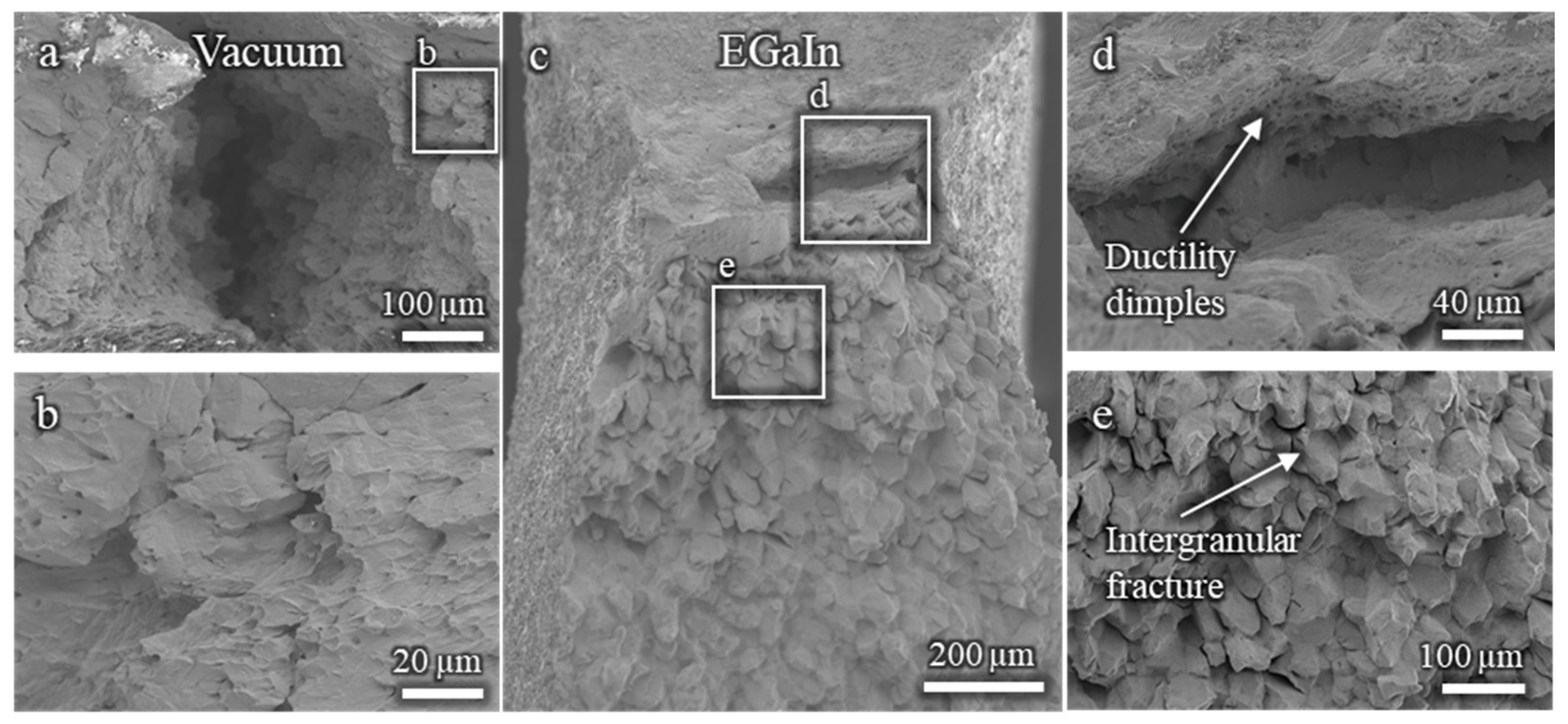
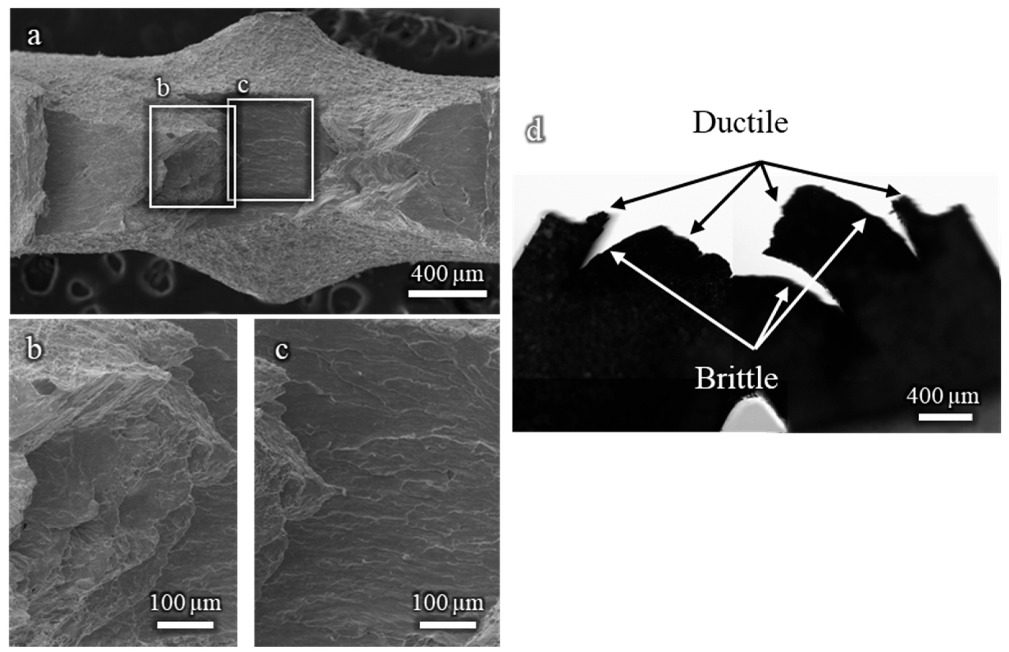
Figure A2 presents the fracture surfaces of a Cu-20%Zn sample tested in contact with liquid EGaIn. The surface reveals alternating zones of ductile and brittle fractures, indicative of a mixed-mode failure. The ductile regions display microvoid coalescence and dimple-like features, typical of plastic fracture behaviour. In contrast, the nature of the brittle zones is less clearly defined. Although they may correspond to intergranular fracture, as in the Cu-30%Zn sample, the heavy plastic deformation of the microstructure impedes its identification. A transverse section of the sample (Figure A2d) highlights this contrast more clearly, showing that ductile cracks propagate vertically and the brittle fractures that propagate horizontally. As for Cu-30%Zn the fracture initiates as ductile.
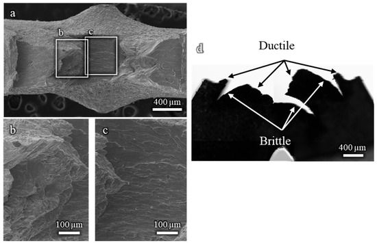
Figure A2.
(a–c) Fracture surfaces of a Cu-20%Zn sample tested in contact with EGaIn, showing alternating ductile and brittle regions. A transverse cut (d) highlights the directional propagation of each fracture mode.
Figure A2.
(a–c) Fracture surfaces of a Cu-20%Zn sample tested in contact with EGaIn, showing alternating ductile and brittle regions. A transverse cut (d) highlights the directional propagation of each fracture mode.
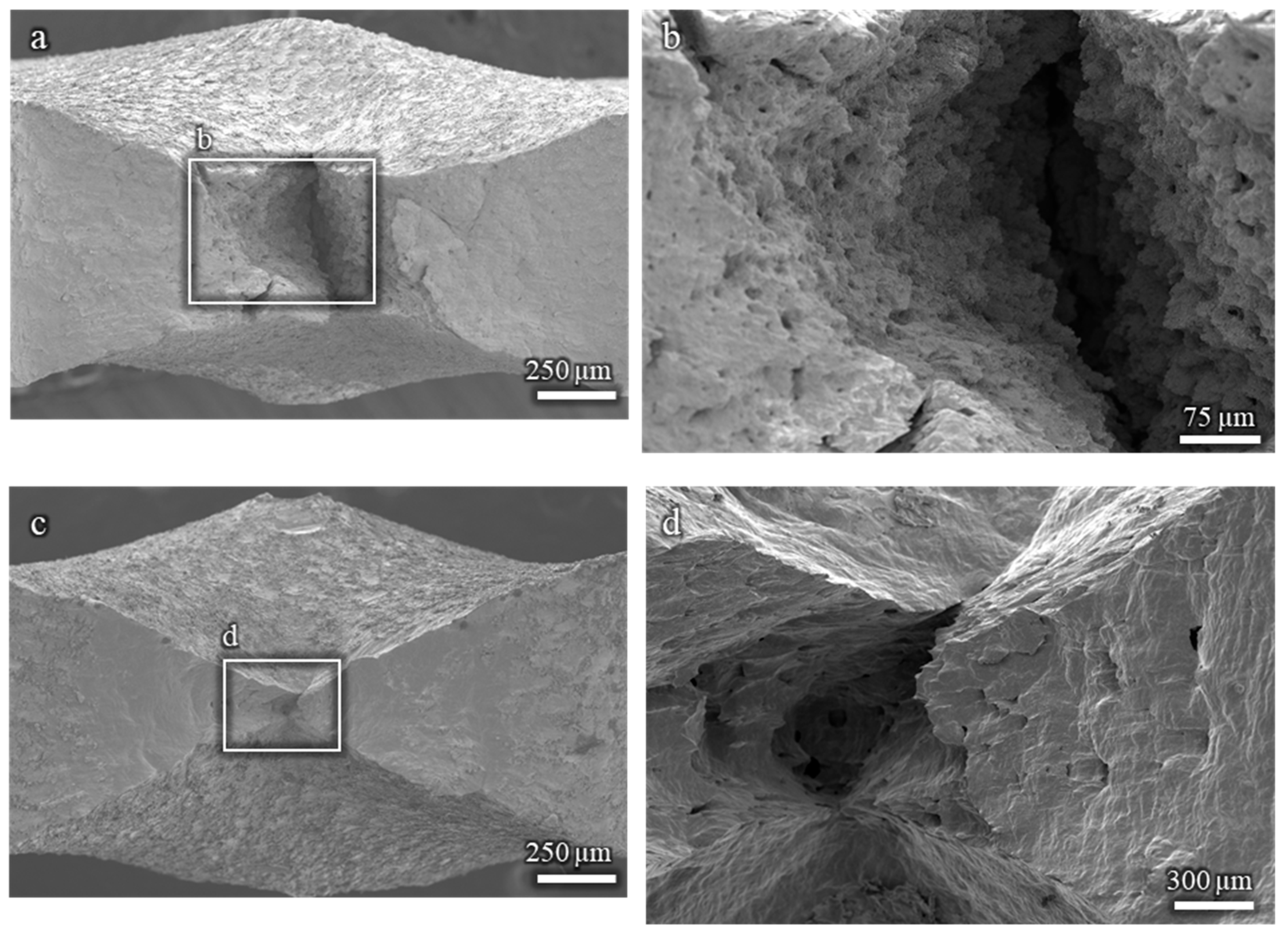
The fractographic analysis of the Cu-15%Zn and pure Cu samples reveals a fully ductile fracture morphology, regardless of the EGaIn. As shown in Figure A3, all fracture surfaces are characterized by ductile features, with no evidence of brittle fracture. These results support the conclusion that neither Cu-15%Zn nor pure Cu undergoes embrittlement under the testing conditions used in this study.
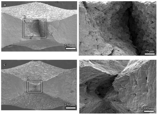
Figure A3.
Fractographies showing ductile fracture surfaces: (a,b) Cu-15%Zn sample; (c,d) pure Cu sample. All tests were conducted in the presence of EGaIn.
Figure A3.
Fractographies showing ductile fracture surfaces: (a,b) Cu-15%Zn sample; (c,d) pure Cu sample. All tests were conducted in the presence of EGaIn.
References
- Gong, X.; Short, M.P.; Auger, T.; Charalampopoulou, E.; Lambrinou, K. Environmental degradation of structural materials in liquid lead- and lead-bismuth eutectic-cooled reactors. Prog. Mater. Sci. 2022, 126, 100920. [Google Scholar] [CrossRef]
- Auger, T.; Vogt, J.-B.; Serre, I.P. Liquid Metal Embrittlement. In Mechanics—Microstructure—Corrosion Coupling; Elsevier: Amsterdam, The Netherlands, 2019; pp. 507–534. [Google Scholar] [CrossRef]
- Razmpoosh, M.H.; DiGiovanni, C.; Zhou, Y.N.; Biro, E. Pathway to understand liquid metal embrittlement (LME) in Fe-Zn couple: From fundamentals toward application. Prog. Mater. Sci. 2021, 121, 100798. [Google Scholar] [CrossRef]
- Ludwig, W.; Pereiro-López, E.; Bellet, D. In situ investigation of liquid Ga penetration in Al bicrystal grain boundaries: Grain boundary wetting or liquid metal embrittlement? Acta Mater. 2005, 53, 151–162. [Google Scholar] [CrossRef]
- Joseph, B.; Barbier, F.; Aucouturier, M. Embrittlement of copper by liquid bismuth. Scr. Mater. 1999, 40, 893–897. [Google Scholar] [CrossRef]
- Hojna, A.; Di Gabriele, F.; Klecka, J. Characteristics and Liquid Metal Embrittlement of the steel T91 in contact with Lead-Bismuth Eutectic. J. Nucl. Mater. 2016, 472, 163–170. [Google Scholar] [CrossRef]
- Gong, X.; Marmy, P.; Yin, Y. The role of oxide films in preventing liquid metal embrittlement of T91 steel exposed to liquid lead-bismuth eutectic. J. Nucl. Mater. 2018, 509, 401–407. [Google Scholar] [CrossRef]
- Norkett, J.E.; Dickey, M.D.; Miller, V.M. A Review of Liquid Metal Embrittlement: Cracking Open the Disparate Mechanisms. Metall. Mater. Trans. A 2021, 52, 2158–2172. [Google Scholar] [CrossRef]
- Nicholas, M.G.; Old, C.F. Liquid metal embrittlement. J. Mater. Sci. 1979, 14, 1–18. [Google Scholar] [CrossRef]
- Ezequiel, M.; Serre, I.P.; Auger, T.; Héripré, E.; Hadjem-Hamouche, Z.; Perriere, L. The liquid metal embrittlement of a reactive system at room temperature: α-brasses in contact with the liquid eutectic Ga-In. Eng. Fail. Anal. 2024, 164, 108694. [Google Scholar] [CrossRef]
- Robertson, W.M. Propagation of a Crack Filled with Liquid Metal. Trans. Metall. Soc. AIME 1966, 236, 1478–1482. [Google Scholar]
- Lynch, S.P. Metal-induced embrittlement of materials. Mater. Charact. 1992, 28, 279–289. [Google Scholar] [CrossRef]
- Liu, S.; Sweatman, K.; McDonald, S.; Nogita, K. Ga-based alloys in microelectronic interconnects: A review. Materials 2018, 11, 1384. [Google Scholar] [CrossRef]
- Ling, K.; Kim, H.K.; Yoo, M.; Lim, S. Frequency-switchable metamaterial absorber injecting eutectic gallium-indium (EGaIn) liquid metal alloy. Sensors 2015, 15, 28154–28165. [Google Scholar] [CrossRef]
- Geddis, P.; Wu, L.; McDonald, A.; Chen, S.; Clements, B. Effect of static liquid galinstan on common metals and non-metals at temperatures up to 200 °C. Can. J. Chem. 2020, 98, 787–798. [Google Scholar] [CrossRef]
- Dickey, M.D.; Chiechi, R.C.; Larsen, R.J.; Weiss, E.A.; Weitz, D.A.; Whitesides, G.M. Eutectic gallium-indium (EGaIn): A liquid metal alloy for the formation of stable structures in microchannels at room temperature. Adv. Funct. Mater. 2008, 18, 1097–1104. [Google Scholar] [CrossRef]
- Yu, J.; Yin, S.; Xiong, G.; Guan, X.; Xia, J.; Li, J.; Zhang, S.; Xing, Y.; Yang, P. Controllable Dealloying of a Cu-Ga Alloy and Its Application as an Anode Material for Lithium-Ion Batteries. J. Electrochem. Energy Convers. Storage 2023, 20, 031007. [Google Scholar] [CrossRef]
- Chen, S.; Lin, J.; Yang, T.; Du, Y. Interfacial Reactions in the Cu/Ga/Co and Cu/Ga/Ni Samples. J. Electron. Mater. 2019, 48, 3643–3654. [Google Scholar] [CrossRef]
- Anderson, T.J.; Ansara, I. The Ga-In (Gallium-Indium) System. J. Phase Equilibria 1991, 12, 64–72. [Google Scholar] [CrossRef]
- Kim, D.; Thissen, P.; Viner, G.; Lee, D.W.; Choi, W.; Chabal, Y.J.; Lee, J.B. Recovery of nonwetting characteristics by surface modification of gallium-based liquid metal droplets using hydrochloric acid vapor. ACS Appl. Mater. Interfaces 2013, 5, 179–185. [Google Scholar] [CrossRef] [PubMed]
- Cui, Y.; Liang, F.; Yang, Z.; Xu, S.; Zhao, X.; Ding, Y.; Lin, Z.; Liu, J. Metallic Bond-Enabled Wetting Behavior at the Liquid Ga/CuGa2 Interfaces. ACS Appl. Mater. Interfaces 2018, 10, 9203–9210. [Google Scholar] [CrossRef]
- Froemel, J.; Baum, M.; Wiemer, M.; Gessner, T. Low-Temperature Wafer Bonding Using Solid-Liquid Inter-Diffusion Mechanism. J. Microelectromech. Syst. 2015, 24, 1973–1980. [Google Scholar] [CrossRef]
- Liu, S.; McDonald, S.; Gu, Q.; Matsumura, S.; Qu, D.; Sweatman, K.; Nishimura, T.; Nogita, K. Properties of CuGa2 Formed Between Liquid Ga and Cu Substrates at Room Temperature. J. Electron. Mater. 2020, 49, 128–139. [Google Scholar] [CrossRef]
- Lin, S.; Cho, C.; Chang, H. Interfacial Reactions in Cu/Ga and Cu/Ga/Cu Couples. J. Electron. Mater. 2014, 43, 204–211. [Google Scholar] [CrossRef]
Disclaimer/Publisher’s Note: The statements, opinions and data contained in all publications are solely those of the individual author(s) and contributor(s) and not of MDPI and/or the editor(s). MDPI and/or the editor(s) disclaim responsibility for any injury to people or property resulting from any ideas, methods, instructions or products referred to in the content. |
© 2025 by the authors. Licensee MDPI, Basel, Switzerland. This article is an open access article distributed under the terms and conditions of the Creative Commons Attribution (CC BY) license (https://creativecommons.org/licenses/by/4.0/).

