Article

The Vanadium Micro-Alloying Effect on the Microstructure of HSLA Steel Welded Joints by GMAW

by
Giulia Stornelli
1,*,
Bryan Ramiro Rodríguez-Vargas
1,
Anastasiya Tselikova
2,
Rolf Schimdt
2,
Michelangelo Mortello
3 and
Andrea Di Schino
1
1
Engineering Department, University of Perugia, Via G. Duranti 93, 06125 Perugia, Italy
2
Vantage Alloys AG, 6300 Zug, Switzerland
3
Italian Institute of Welding (IIS), Sede di Genova, Lungobisagno Istria 15, 16141 Genova, Italy
*
Author to whom correspondence should be addressed.
Metals 2025, 15(10), 1127; https://doi.org/10.3390/met15101127
Submission received: 5 September 2025 / Revised: 29 September 2025 / Accepted: 8 October 2025 / Published: 10 October 2025

Abstract

Structural applications that use High-Strength Low-Alloy (HSLA) steels require detailed microstructural analysis to manufacture welded components that combine strength and weldability. The balance of these properties depends on both the chemical composition and the welding parameters. Moreover, in multi-pass welds, thermal cycling results in a complex Heat-Affected Zone (HAZ), characterized by sub-regions with a multitude of microstructural constituents, including brittle phases. This study investigates the influence of Vanadium addition on the microstructure and performance of the HAZ. Multi-pass welded joints were manufactured on 15 mm thick S355 steels with different Vanadium contents using a robotic GMAW process. A steel variant containing both Vanadium and Niobium was also considered, and the results were compared to those of standard S355 steel. Moving through the different sub-regions of the welded joints, the results show a heterogeneous microstructure characterized by ferrite, bainite and martensite/austenite (M/A) islands. The presence of Vanadium reduces carbon solubility during the phase transformations involved in the welding process. This results in the formation of very fine (average size 11 ± 4 nm) and dispersed precipitates, as well as a lower percentage of the brittle M/A phase, in the variant with a high Vanadium content (0.1 wt.%), compared to the standard S355 steel. Despite the presence of the brittle phase, the micro-alloyed variants exhibit strengthening without loss of ductility. The combined presence of both hard and soft phases in the HAZ provides stress-damping behavior, which, together with the very fine precipitates, promises improved resistance to crack propagation under different loading conditions.

1. Introduction

High-Strength Low-Alloy (HSLA) steels are micro-alloyed steels characterized by outstanding mechanical strength and excellent weldability that enable cost and weight reductions [1,2,3,4,5,6]. These steels include micro-alloying elements such as niobium (Nb), titanium (Ti) and/or Vanadium (V) in very low amounts, enabling their use in the manufacturing process of pipelines, storage tanks, pressure vessels, and thick-walled components for the energy sector [7,8,9,10].
Despite the key role of micro-alloying elements in developing high-strength and high-toughness steels [11], their use has long been limited by the degradation of structural stability in welded joints [12]. Thermal cycling during welding processes alters the microstructure of HSLA steels, generating Heat-Affected Zones (HAZs) with complex and potentially low toughness microstructures. For this purpose, proper identification of the welding process and optimization of the operating parameters are critical to ensuring high-quality joints [13,14,15].
Gas Metal Arc Welding (GMAW) is a widely used welding technique, especially in the energy sector. Its versatility enables both manual and robotic operations, facilitating joint manufacturing with a large variety of materials and thicknesses, in different positions [16,17,18,19,20]. However, despite the well-known advantages of the GMAW process, the Welded Zone (WZ) and the HAZ are exposed to high heat input. This is necessary for multi-pass welding of medium-to-high-thickness plates under real production conditions and poses a significant challenge in terms of controlling the microstructure and mechanical properties of HLSA steels [21,22,23].
Indeed, the high thermal gradients involved in the HAZ lead to partial or complete austenitization [21,24,25], followed by rapid cooling and the consequent formation of more brittle phases such as martensite, bainite, and/or high-ferrite side-plate fractions.
For multi-pass welding, the Coarse-Grain Heat-Affected Zone (CGHAZ) and the Inter-Critical Coarse-Grain Heat-Affected Zone (ICCGHAZ) are sub-regions of the HAZ in which the resulting microstructural constituents contribute to not only enhanced structural–mechanical resistance but also cause a loss of toughness and fatigue strength [24,26,27,28,29,30,31,32]. In particular, the ICCGHAZ is the portion of the CGHAZ which underwent reheating within the inter-critical range temperature, between AC1 and AC3, during multi-pass welding [33,34]. During the inter-critical thermal cycle, a partial transformation into austenite occurs, especially in the Pearlite/bainite colonies [34]. During cooling, these high carbon regions re-transform into Pearlite/bainite and martensite/austenite (M/A) [33,35,36]. Several studies have identified the ICCGHAZ as a region with low fracture toughness for the HLSA steels, which is precisely due to the formation of M/A islands [26,37,38,39,40], which have a detrimental effect on both crack initiation and propagation [12,41,42,43]. It was established that the greater the size and volume fraction of the M/A phase, the greater the loss in toughness [21,44,45,46] due to its tendency to act as a preferential fracture site. Moreover, some authors have also pointed out that the distribution and morphology of M/A islands also affect the mechanical behavior of the welded joint, in addition to size and volume fraction [12,44,47].
As is well known, Nb is widely used in HSLA steels to increase mechanical strength. However, it has been shown to reduce the fracture toughness of the HAZ when medium- to high-heat-input welding is applied [35]. A small amount of Nb suppresses ferrite nucleation at Prior Austenite Grain (PAG) boundaries and increases the volume fraction of either martensite or bainite [48,49,50]. Previous studies have reported that the advantages of adding Nb, i.e., grain refinement and the improvement of the base metal mechanical properties, are outweighed by the detrimental effects of M/A formation when steel plates are welded [50,51].
On the other hand, V is considered a key element in the metallurgical design of HSLA steel welds, offering efficient and cost-effective solutions across a broad range of applications [52,53]. The relevance of V adoption mainly relates to its thermodynamic and kinetic properties to form precipitates as carbo-nitrides. These precipitates promote strengthening and, under well-defined conditions, act as nucleation sites for some specific phases during heat treatment and/or welding [53,54,55,56]. Moreover, in addition to strengthening by precipitation, V also contributes to grain refinement in HSLA steels. These constitute the key points for obtaining welded joints in HSLA steels with good toughness and high strength. Fazeli et al. [53] shown that the addition of a small amount of V promotes the refinement of the final ferrite microstructure (up to 5–10 µm). Moreover, Wu et al. [57] indicated that ultra-fine ferrite and V(C,N) precipitates formed in the welding process are important factors affecting the toughness of the joints. The V(C,N) precipitates play a role in refining the M/A island size down to 1 μm. In addition, the C content is reduced in the M/A island, with a consequent decrease in hardness and improved toughness of the joint. Mitchel et al. [50] reported that V micro-alloyed steels exhibit higher tolerance to increased welding heat input compared to those micro-alloyed with Nb. Kalantar et al. [58] investigated the strength and impact energy after inter-critical heat treatment in low-carbon micro-alloyed cast steels containing V and Nb. They showed that the impact energy of the alloy containing only V was higher than that of the materials containing Nb. Chen et al. [59] presented that the addition of about 0.05 wt.% of V to low-carbon low-alloy steels results in a balance of strength and toughness in the HAZ, while with 0.097 wt.% and 0.151 wt.% V, the M/A content is higher.
In this framework, the present work provides a systematic investigation of Vanadium micro-alloying effects on HSLA steel welded joints, with particular attention to microstructural and performance evolution in the HAZ. Although the influence of Vanadium has been widely examined in relation to conventional and advanced heat treatments, its specific role during welding—and the resulting HAZ alteration—remains an open and highly relevant topic, especially for medium- and high-thickness (>10 mm) welded plates [60,61,62]. To address this gap, the present study focuses on S355 steel, evaluating the impact of V addition on both the WZ and the HAZ. The investigation was conducted on joints starting from 15 mm thick plates using a robotic GMAW multi-pass process, enabling detailed microstructural and mechanical characterization across the various sub-regions of the HAZ.

2. Materials and Methods

2.1. Materials

In this paper, S355-grade steel plates for structural application (EN10025-2), with different V contents, were used as the Base Metal (BM) to manufacture welded joints. The chemical compositions of the BM and filler metal are shown in Table 1. The filler metal employed was ER70S-6 (1.2 mm). The steels were produced in a pilot plant by Vacuum Induction Melting (VIM) in the form of four 80 kg ingots (diameter: 120 mm). These were then hot-rolled to a thickness of 15 mm in 10 passes.
The microstructure of the BM, as shown in Figure 1, is mainly composed of a Polygonal ferrite (PF) matrix with Pearlite (P) organized in bands, as typical of hot-rolled steel [63]. No significant variations are observed, in terms of microstructural constituents and their distribution, between the Base Variant (BV) and the micro-alloyed steels, Variant I (V-I), Variant II (V-II), and Variant III (V-III).

2.2. Welding Procedure

Multi-pass welded joints were manufactured using a robotic GMAW process on a welding layout, as shown in Figure 2. For the V-groove butt joint configurations, the plates were machined at a 60° angle. The GMAW spray transfer mode was employed utilizing a shielding gas mixture composed of 85% Ar and 15% CO2 at a flow rate of 18 L/min. The welding operation parameters for the different joints are shown in Table 2.
The heat input was calculated according to Equation (1):
Heat   Input = η   ×   I · V · 60 W S · 1000
where I (A) and V (V) are the current and voltage averaged over each pass and WS (mm/min) is the welding travel speed. We used an arc efficiency of h = 0.90 (typical for the GMAW spray transfer mode). Heat input values are reported per weld pass as ranges reflecting the operational variability. This methodology allows for a quantitative correlation between pass-by-pass heat input and the observed HAZ microstructural.
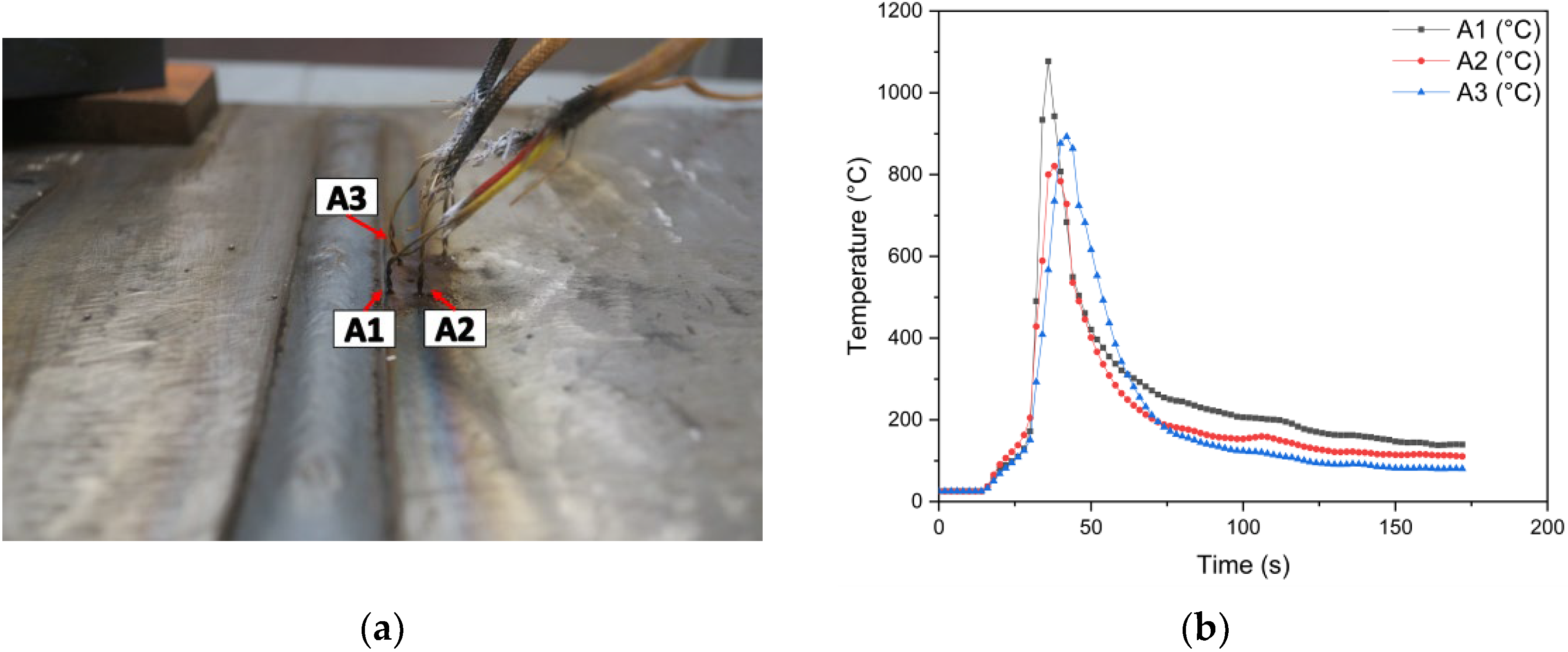
The t8/5 value was evaluated considering a single weld bead on a representative plate of V-II. The plate was instrumented employing 3 thermocouples (K type), A1, A2, and A3, positioned, respectively, at a distance of < 1 mm, 5 mm, and 3 mm from the weld toe (see Figure 3a). The profiles acquired by the thermocouples are shown in Figure 3b, which correspond to a t8/5 value of 6–10 s. The acquisition of the thermal profiles was performed using a data logger, with a sampling interval of 2 s. As can be seen, the maximum temperature reached near the weld bead is about 1070 °C (thermocouple A1), while at 5 mm, the maximum temperature reached is about 790 °C (thermocouple A2).

2.3. Macro/Microstructural Characterization

Metallographic specimens were machined starting from the joint and prepared by conventional metallographic techniques in accordance with the ASTM E3 standard [64] to analyze the macro- and microstructural characteristics. Nital-2% etching (2 mL of HNO3 + 100 mL of C2H5OH) was applied for 10 s to assess the macrography and micrography of the welded joints. Additionally, the LePerà reagent (a 4% w/v solution of C6H3N3O7 in C2H5OH, combined with a 1% w/v solution of Na2S2O5 in H2O) was used for about 60–90 s to better identify microstructural phases characterized by different carbon contents. As a matter of fact, color etching highlights phases based on the carbon content: The ferrite (F) phase is colored in dark brown. Bainite (B) and tempered martensite are light brown. Pearlite (P) is colored in very light brown, and martensite/austenite (M/A) appears as distinct white islands [65]. In order to examine the welded joint macrostructure, a stereoscope (SMZ-745T, Nikon, Tokyo, Japan) was used, while the microstructure was assessed by an Optical Microscope (Eclipse LV150, Nikon, Tokyo, Japan) equipped with a dedicated software (AlexaSoft, X-Plus, Florence, Italy) to perform image analysis, which was exploited to estimate the M/A volume fraction. This analysis was performed in 10 different fields for each steel variant; therefore, the M/A content (%) reported refers to an average of these values. To support the microstructural analysis, simulations were performed using the JMatPro software (Demo Version).
The precipitation state in the ICCGHAZ was analyzed by a Transmission Electron Microscope (TEM) on extraction replica specimens in the three micro-alloyed variants (V-I, V-II, and V-III). The observations were performed with a JEOL 200CX transmission electron microscopy (JEOL Ltd., Tokyo, Japan). The analysis was carried out over a significant area, evaluating the chemical composition (by means of Energy-Dispersive X-ray (EDX) analysis) and average size of the precipitates, within a limit of 50 precipitates for each sample analyzed.

2.4. Evaluation of Mechanical Properties

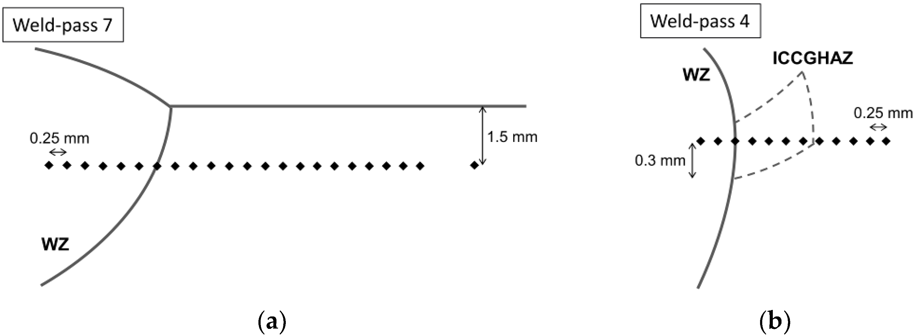
Vickers Hardness (HV) tests were performed by means of HV50 (Remet, Bologna, Italy) instruments by using a load of 1 kgF. For the four steel variants, hardness profiles were measured in different areas of the joint (Figure 4). In particular, the WZ, HAZ, and BM were examined in the upper part of the weld (Figure 4a—corresponding to weld pass 7 in Figure 2) and, similarly, in the area corresponding to the ICCGHAZ (Figure 4b—at weld pass 4 in Figure 2).
Additionally, nanoindentation tests were performed for V-II in specific areas of the HAZ of greater interest (WZ, CGHAZ, and ICCGHAZ), with the aim to clearly detect the M/A and study its influence on mechanical behavior. A nanoindenter with an RTec instrument (RTEC-INSTRUMENTS Inc., San Jose, CA, USA) was used, employing a load of 100 mN and a hold time of 10 s.
Finally, tensile tests were performed on the full-thickness welded joint in a calibrated universal tensile testing machine (A014-TC200, LBG testing equipment, Bergamo, Italy) which a 200 kN capacity. A drawing of a probe used in tensile tests is shown in Figure 5. For each steel variant, three tests were carried out, and the curves revealed high reproducibility. The tensile tests were carried out according to the ISO 6982 standard [66].

3. Results

3.1. Macrostructure of Welds

The macrostructural evaluation (Figure 6) shows that complete joint penetration was achieved in all welds. The weld geometry is uniform, with no visible defects such as undercuts, porosities, or hot cracks. This indicates that the explored welding parameters are suitable for ensuring joint integrity. In each of the welds, a notable increase in the HAZ at the root is observed. This is due to the design of the welding procedures; in particular, the initial passes (root pass and hot pass) are designed to ensure proper fusion and initial penetration. As shown in Table 1, a lower welding current and speed are used, which are typical of the root pass (weld pass 1 in Figure 2), ensuring good penetration without overheating the weld base. Subsequently, the hot pass (weld pass 2 in Figure 2) uses a higher current and a lower feed speed compared to weld pass 1, allowing the heat to penetrate deeper and over a larger area near the weld root. This results in a widening of the HAZ. Finally, the parameters are gradually increased to fill the welding groove and ensure complete fusion of the subsequent weld beads. Moreover, the reduced heat input in the later passes is due to the preheating effect generated by the initial passes and the increased welding speed, which allow the current to remain constant. This helps to avoid overheating the previously welded structure and minimizes thermal shocks with the surrounding atmosphere [67,68].
These observations highlight the significant impact of local heat input on HAZ development. High heat input results in slower cooling and a widening of the HAZ. It also promotes grain growth and increases hot-cracking susceptibility by enhancing segregation at grain boundaries and reducing high-temperature ductility. Conversely, low heat input accelerates cooling, producing finer but more brittle microstructures (e.g., fine martensite) and higher thermal stresses, which can also promote cracking [69,70]. For S355 steel, no universal threshold exists, as sensitivity depends on the composition, joint geometry, welding technique, and cooling rate [69,71,72]. In this study, the calculated heat input for each pass (see Table 2) and the subsequent HAZ analysis show that the selected parameters strike a suitable balance between cooling rate, solidification, and microstructural evolution.

3.2. Microstructure Characterization

3.2.1. The Welding Zone

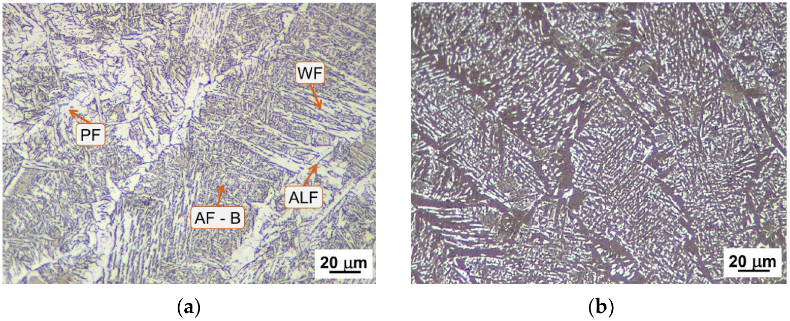
Figure 7 shows, as an example, the microstructure in the WZ for V-II (high V). For the other steel variants, the same microstructural characteristics were obtained. The micrographs refer to the upper zone of the welded joint (see weld pass 7 in Figure 2) and are used to analyze a structure free from any thermal alteration due to the subsequent welding passes. However, in a multi-pass welding, each welding pass causes the alteration of the microstructure of the pre-solidified welded joint portion, resulting in softening [73,74]; a brief analysis is reported in Appendix A. The WZ is organized according to columnar solidification structures arranged along the thermal gradient of heat removal, and within these structures, it is possible to distinguish some microstructural constituents: Polygonal ferrite (PF) and Allotriomorphic ferrite (ALF) with, in small quantity, secondary transformation products in the form of Widmanstätten ferrite (WF), acicular ferrite (AF), bainite (B), and the M/A phase. It is known that the solidification of the microstructure is mainly influenced by (1) the filler metal chemical composition, which is specifically designed to promote weldability and ensure good mechanical properties, and (2) the nature of the GMAW process and the welding parameters, as they promote strong thermal gradients in the molten pool, influencing the rate and direction of solidification [75,76]. As a result, the analyzed joints present a heterogeneous microstructure, independent of the chemical composition of the Base Metal. It is important to highlight that during rapid cooling of the WZ, ALF tends to nucleate on the PAG boundary and acts as a nucleation site for the other above-mentioned constituents, typically occurring towards the center of the PAG. Furthermore, the distribution of the different constituents is influenced by the welding heat input (HI) [77,78]. As shown in Figure 7, AF appears at an intragranular position in a mixture with ferrite and bainite [79,80,81]. On the other hand, for WF, its formation occurs through a paraequilibrium mechanism, where carbon atoms diffuse across the advancing interface into the austenite during the phase transformation. The presence of WF is not in itself a sign of metallurgical damage: several works have shown satisfactory mechanical properties when the grain size and/or thermal history are properly controlled [82,83,84]. Overall, the WF microstructure requires low undercooling for its formation. However, thanks to the high undercooling involved in welding, microphases such as M/A and/or ferrite–carbide aggregates are favored between the growing ferrite plates [81]. Indeed, as shown in the micrographs obtained after LePerà etching (Figure 7b), white areas rich in carbon are clear at the boundary of ALF, AF, WF, and B. Moreover, solidification-induced segregation promotes the formation of areas with high solute and carbon contents, which can induce the formation of M/A constituents. In this respect, for a correct interpretation of the microstructure, it is important to clarify that the white areas identified by LePerà etching in the WZ and, more generally, within the solidification structures tend to overestimate the M/A content. This overestimation is due to the complexity of the microstructure, which makes it difficult to accurately distinguish between the segregation and carbon-rich zones present at the edges of the constituents.

3.2.2. The Heat-Affected Zone

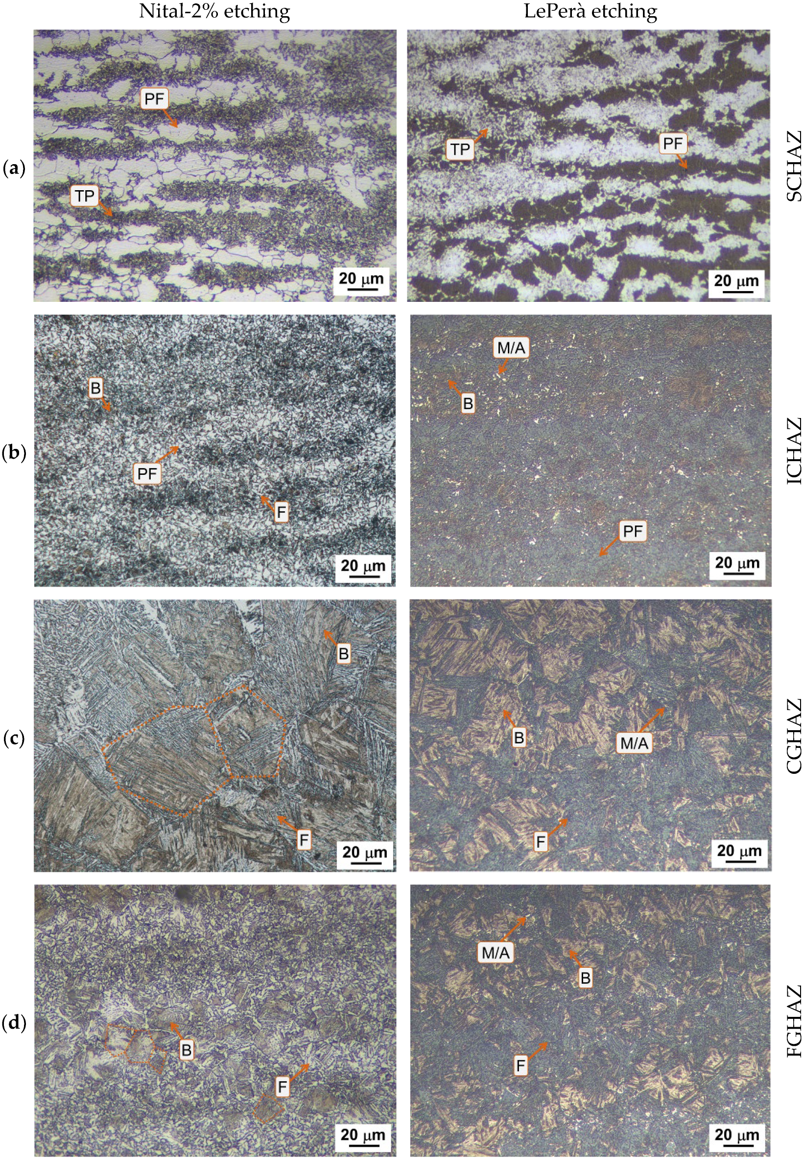
The microstructural composition is influenced by several factors including the chemical composition and initial microstructure of the BM, the welding process, the heat input exploited, and the thickness of the plate. These factors contribute to defining the cooling rate and the consequent microstructural evolution and mechanical behavior of the joint [85]. The HAZ can be described based on the thermal cycle undergone by the material (Figure 8): the Sub-Critical HAZ (SCHAZ), the Inter-Critical HAZ (ICHAZ), the Fine-Grain HAZ (FGHAZ) and the Coarse-Grain HAZ (CGHAZ). Each of these zones is reported in Figure 9 for the V-II (high V) steel. A detailed overview of the microstructure of all steel variants is given in Appendix B, which compares each of these variants in the different sub-regions of the HAZ.
In addition, in a multi-pass weld, the Inter-Critical Coarse-Grain HAZ (ICCGHAZ) is present, i.e., the CGHAZ portion that undergoes a partial re-transformation in the inter-critical temperature range.
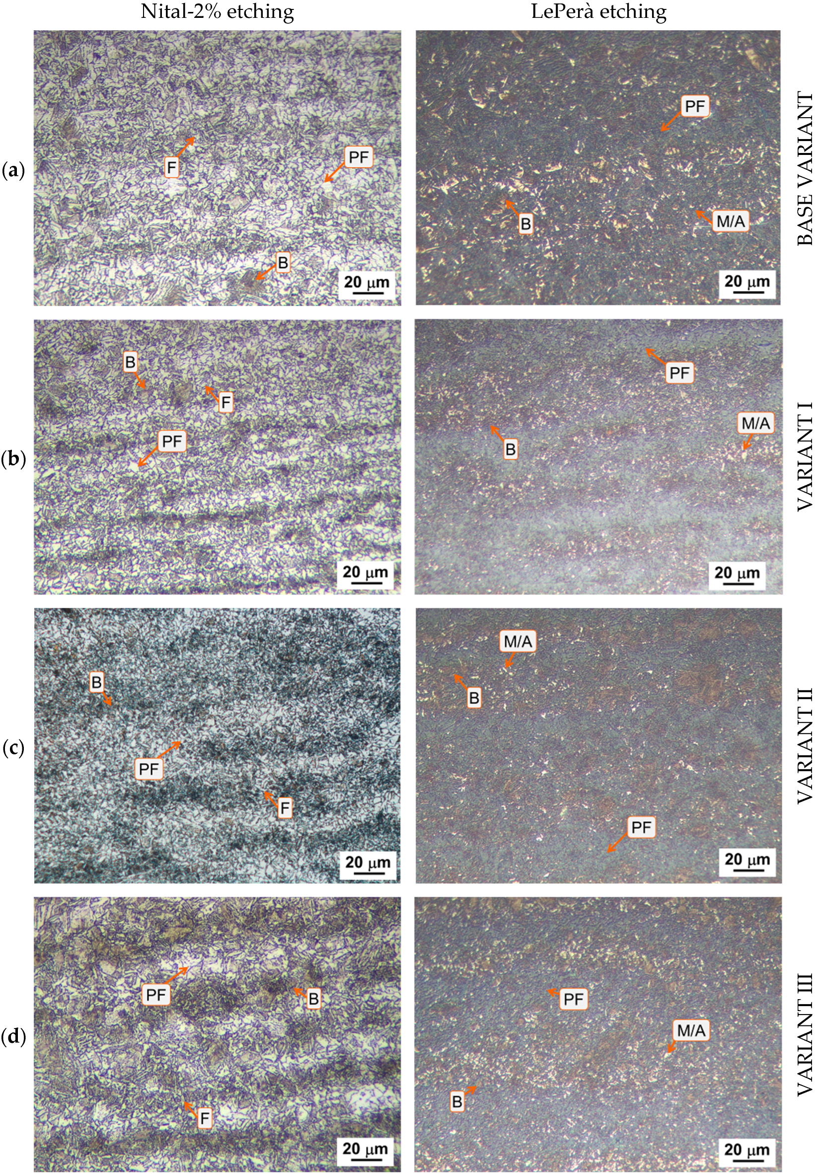
In the SCHAZ (Figure 9a), temperatures remain below the temperature of the eutectoid transformation of the steel, preventing it from reaching the temperature for complete or partial austenitization. The result is a microstructure similar to that of the BM, which mainly consists of a matrix of Polygonal ferrite (PF) with degenerated and partially transformed Pearlite (TP). As for the ICHAZ (Figure 9b), the microstructure is composed of large areas of PF and areas composed of B and F. Additionally, from the micrographs obtained using LePerà etching, small white islands can be observed and are attributable to the M/A phase. It is well known that the formation of this phase is common in the HAZ of welded joints, such as in areas that undergo partial or total austenitization. Due to rapid cooling, the diffusion phenomena are not favored, and the carbon stays as a solid solution in the austenite phase, promoting the formation of M/A during rapid cooling [86]. Overall, the organization of the microstructure appears banded like in the BM, showing no significant differences between the four steel variants, except for a minor amount of M/A in V-II (see Figure A4 in Appendix B).
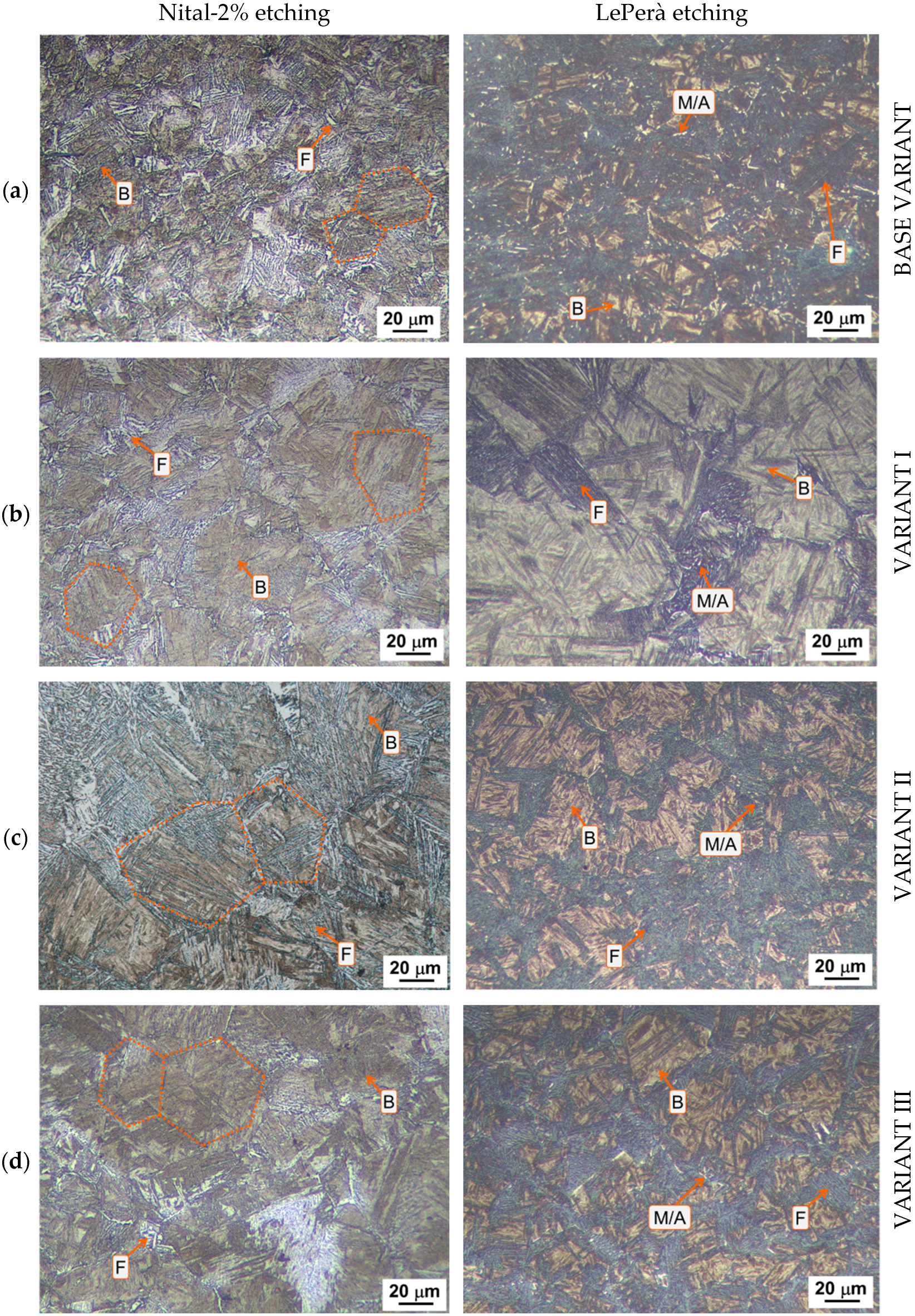
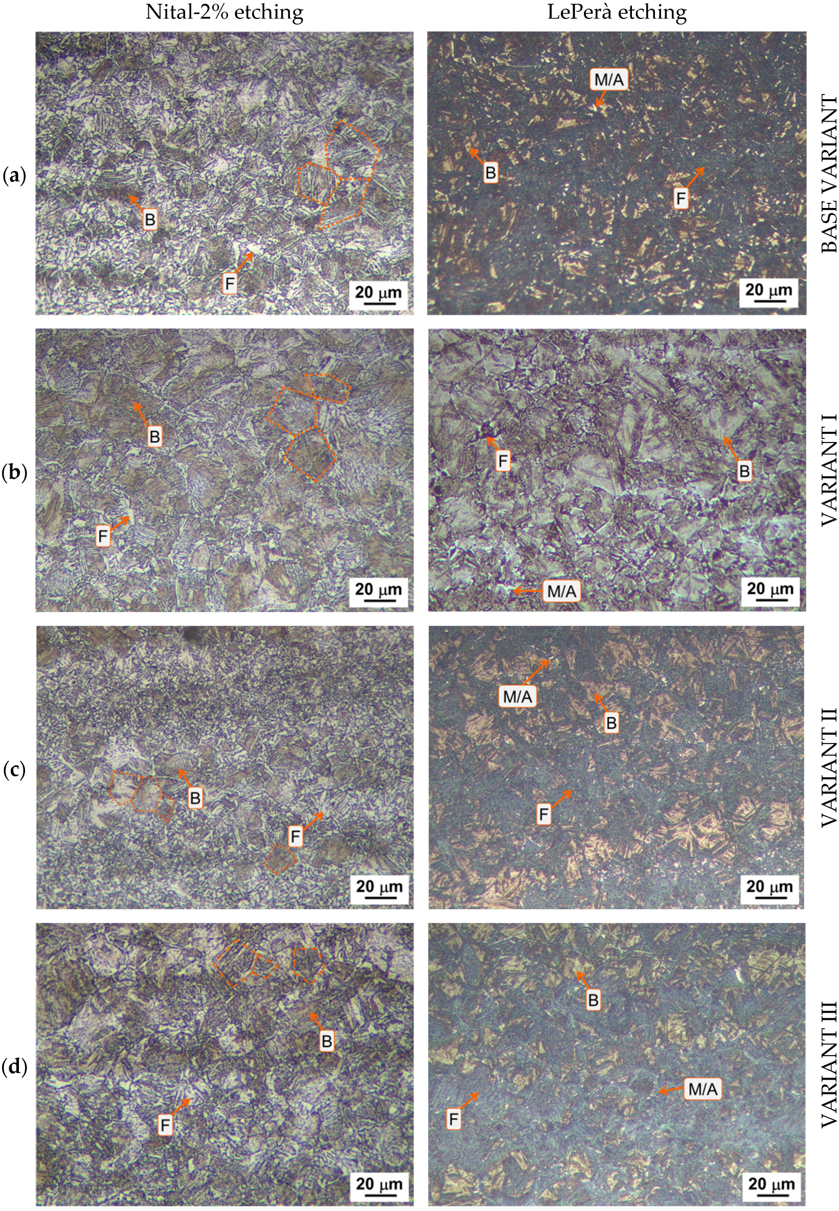
In Figure 9c,d the CGHAZ and FGHAZ are presented, with the microstructure composed mainly of Bainite (B) within the PAG and small islands of Ferrite (F) with different morphology, both ALF and WF, at the PAG boundaries. Moreover, there are some small M/A islands. The main distinction between the CGHAZ and the FGHAZ is the sizes of the PAG. In particular, the average grain size in the CGHAZ ranges between 30 and 40 µm in the different variants, whereas in the FGHAZ, it is about 15–20 µm. A comparison of the steel variants shows that BV exhibits greater ferrite (ALF and WF) presence along the PAG boundaries, with reduced bainite formation, while the micro-alloyed variants show a prevalence of B. Moreover, the amount of the M/A phase appears to be minimal in the micro-alloyed variants (M/A% < 1%) compared to the BV (M/A% up to 2.5%), especially in the FGHAZ (see Figure A5 and Figure A6 in Appendix B).
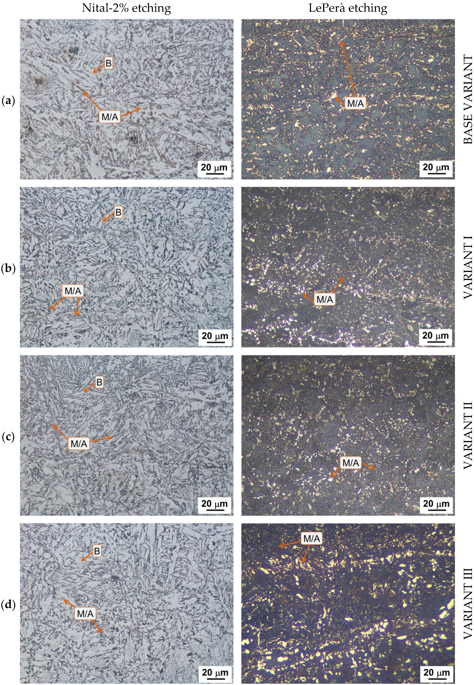
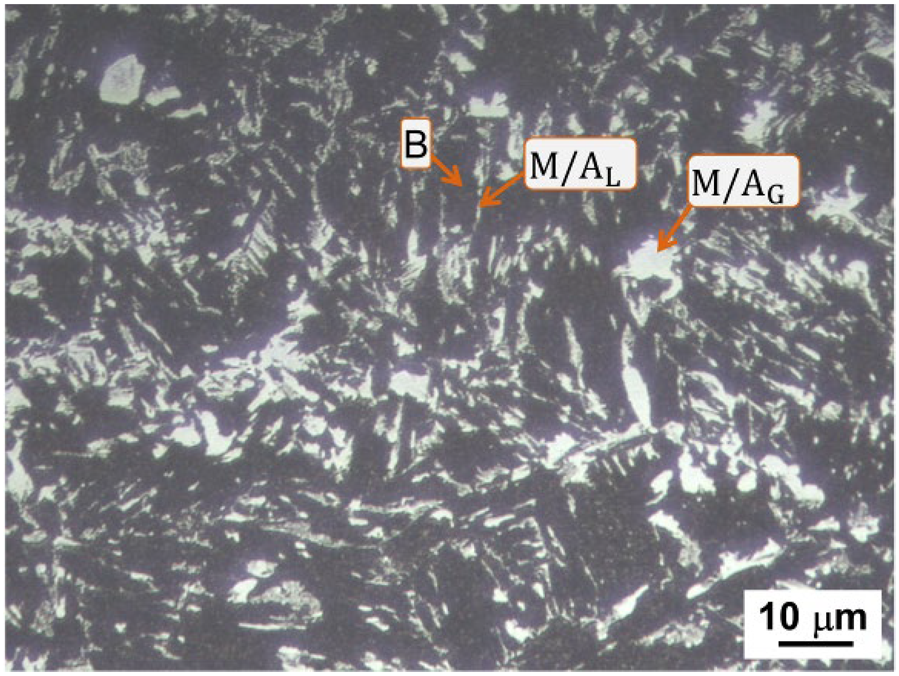
Figure 10 shows a detail of the HAZ for V-I, where the ICCGHAZ can be distinguished. This configuration is valid for all steel variants. Moreover, Figure 11 shows the microstructure of the ICCGHAZ for the four steel variants. The main microstructural constituents of the ICCGHAZ include B, as well as well-defined islands of M/A with lamellar (M/AL) and granular (M/AG) morphologies, as shown at high magnification in Figure 12 for V-I. The M/AL is mainly located between the boundaries of B, while the M/AG is arranged along bands, with a preference in the zones enriched with carbon or gamma-stabilizing elements such as Mn [63], which were previously segregated in the Base Metal and in the CGHAZ.
From Figure 11 it is possible to distinguish different sizes of the M/A phase between the four variants, and this is mainly true for the M/AG with a larger size in the BV and V-III. For V-II, the latter appears finer and well distributed within the microstructure, suggesting a beneficial effect on mechanical behavior. Table 3 reports the results of the qualitative quantification of the M/A fraction obtained by image analysis after LePerà etching. The micro-alloyed variants have a lower M/A content than the BV; moreover, the lowest value belongs to V-II (5.4% vs. 8.9%). Additionally, contrary to what was expected [35,49], the addition of Nb does not significantly contribute to M/A formation. The low Nb content (0.02 wt.%) does not appear sufficient to evidence the detrimental effects induced by this element.
It should be noted that although this investigation is useful to study the different microstructural constituents in the ICCGHAZ of HLSA steels, the reported M/A percentages represent a qualitative estimate. Typically, this technique leads to an overestimation of the phase amount due to the coloring effect of the LePerà etching process, which can similarly highlight complex carbon-rich phases. However, these results agree with the results reported in previous work [34], in which the ICCGHAZ was simulated for the same steel variants. In that case, the M/A fraction was estimated not only with the LePerà etching method but also with X-ray diffraction and Electron Backscatter Diffraction techniques. The results obtained with Electron Backscatter Diffraction showed an amount of M/A that was always below 0.6%, making it impossible to identify by X-ray diffraction.
As shown in Figure 13, another relevant microstructural feature is the precipitation state in the ICCGHAZ of the micro-alloyed variants while only considering V-rich and Nb-rich precipitates. EDS analyses of some of them, with reference to the spectra reported in Figure 13, are shown in Table 4 as representative examples. For the steel variants alloyed with V only (V-I and V-II), very small V-rich precipitates were detected. For both these steels, the average size of the precipitates is about 11 ± 4 nm, and all the precipitates analyzed have sizes smaller than 20 nm. The scenario is different for the variant containing both Nb and V, where larger precipitates are rich in Nb only or in both Nb and V, with an average size of 35 ± 40 nm and a maximum size over 250 nm. It is worth mentioning that V is always present in the combination with Nb, and only 40% of the Nb-V-rich precipitates have a size smaller than 20 nm.

3.2.3. Mechanical Behavior of Welded Joints

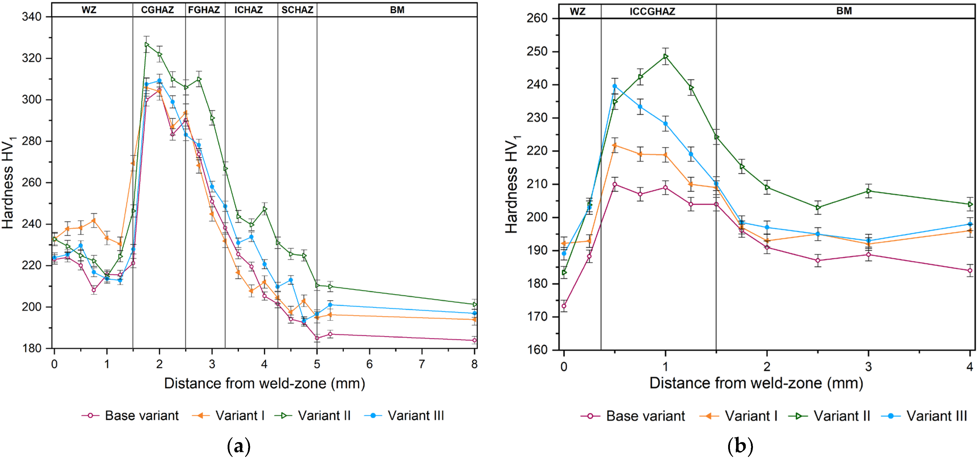
The hardness behavior in the HAZ of the four steel variants is reported in Figure 14. In particular, Figure 14a refers to the upper part of the weld, as reported in the schematization in Figure 4a, while Figure 14b refers to the ICCGHAZ, in accordance with the schematization in Figure 4b. As expected, the BM shows a minimum hardness value in the BV (181 ± 4 HV1) and higher values in the variants with the addition of micro-alloyed elements: 195 ± 1 in V-I, 209 ± 6 in V-II, and 197 ± 4 in V-III. In all cases, this value increases as it approaches the HAZ and decreases in the weld zone. In the HAZ, V-II presents higher hardness values than the other variants, which show similar trends. For V-II, it is pertinent to attribute these hardness deviations to the higher content of micro-alloyed element, as these deviations are visible starting from the BM. This strengthening can be attributed to the presence of very fine V-rich precipitates, such as carbides. The presence of the M/A phase in the HAZ does not justify such a deviation since it appears to be present on each variant. Differently, for the BV, the hardness increase, and it cannot be attributed to the presence of fine precipitates but rather to the presence of the hardest microstructural constituents. This behavior appears to agree with what was observed by microstructural analysis.
As for the ICCGHAZ, the scenario is slightly different (Figure 14b), V-II always presents the highest hardness values, while the other two micro-alloyed steels have higher hardness values than the BV. However, it should be noted that the maximum hardness values achieved in this zone are significantly lower than the values shown in Figure 14a. The continuous heating experienced by the first welded parts of the joint attenuates the hardening and concern related to the welding process in the ICCGHAZ.
To better understand the influence of microstructural constituents on mechanical behavior, following the identification of the M/A phase by LePerà etching, nanoindentation tests were performed on various zones for V-II, in the WZ, CGHAZ, and ICCGHAZ, respectively. Operatively, the ability to distinguish the M/A phase allowed us to perform nanoindentation tests in areas with high or low M/A concentrations. Figure 15 shows the nano-hardness profiles identified on the indicated zones. Profiles A and B refer to the WZ and CGHAZ, respectively. Conversely, for the ICCGHAZ, profiles C and D refer, respectively, to areas with low and high content of M/A.
In Table 5, the average values of the maximum indentation depth (hmax), elastic modulus (E), nano-hardness (H), plastic work (Wp), elastic work (We), and residual depth after unloading (hf) are summarized for the four profiles. The punctual results of the nanoindentation tests are given in the Appendix C.
Profile A shows remarkable elastic mechanical resistance in the WZ, with an average elastic modulus of 171.1 ± 8.8 GPa, which can be related to the presence of ferrite in different morphologies and the M/A phase. Conversely, profile C (the ICCGHAZ with low M/A content) has an average elastic modulus of 154.12 ± 14.45 GPa, which is unlike profiles B and D with slightly higher and similar modulus values (166.3 ± 24.3 GPa and 167.8 ± 36.3 GPa, respectively). The high standard deviation of the elastic modulus in profiles B and D suggests greater variability in the measurements and therefore in the constituents, as also observed by microstructural investigation. Indeed, the presence of M/A with a non-homogeneous distribution creates areas with different plastic/elastically behaviors, which affect the local elastic modulus. These results align with the nano-hardness values (H), where a notable increase in this property is observed in the area with a higher amount of M/A. The consistency in hardness values between both zones indicates that the measurements are reliable and reflect the microstructural differences in the various zones.
Finally, the results of the tensile tests of the welded joints are summarized in Table 6. The results show that the addition of micro-alloyed elements such as V and Nb-V, even if in a low percentage (0.05 wt.% in V-I), strengthens the joint without sacrificing ductility, maintaining both total and uniform elongation (A and Au). Furthermore, despite the strengthening, the ratio between the yield stress and the ultimate tensile stress remains lower than 0.8%. Therefore, for all steel variants, the reported values are in accordance with what is required by the standard of the BV (EN10025-2). The breaking zone is, for all joints, in the BM (about 30 mm from the WZ) (Figure 16), which suggests that the welding parameters used are adequate to ensure welded components with the necessary strength and safety.

4. Discussion

This work focuses on the effect of micro-alloyed V addition to HSLA steel joints welded by the multi-pass GMAW process in the presence of Nb. The joints were produced whit seven weld passes, and the welding parameters were intentionally varied between passes (see Table 2) to control the local heat input and the cooling rates, thereby limiting excessive coarsening and controlling microstructural transformations in the different HAZ sub-regions. This is relevant because during the welding process, depending on the heating temperature, different microstructural variations occur in the HAZ, with consequent alteration of the mechanical behavior of the component. The starting microstructure of the BM is always Polygonal ferrite and Pearlite. In the HAZ of all steel variants, the initial microstructure is replaced with other constituents such as B, F (the latter in the form of ALF and WF) and M/A islands. It is known that during rapid cooling starting from an austenitic temperature, the austenite-to-ferrite decomposition involves the formation of ALF at the austenite boundaries, from which, with continued cooling, WF grows towards the austenitic grain center [87,88,89]. In addition, two competing scenarios can generally occur during further low-temperature cooling: the nucleation of intergranular AF from inclusions/precipitates or, in the absence of effective inclusions/precipitates, B formation starting from the PAG boundary and/or ferrite/austenite boundaries [88,90]. From the literature, the beneficial effect of V addition on the preferential formation of AF in the welded joints of HSLA steels clearly emerges [56,91,92]. However, differently from what was expected, in the present work, it was not possible to identify AF in the HAZ of the micro-alloyed steel variants. In fact, V addition alone is not a sufficient condition for AF formation. Based on energetic considerations, intergranular nucleation on inclusions/precipitates is disfavored compared to nucleation on boundaries [86,91,92]. As long as free boundaries are present, the bainitic transformation kinetics will be faster than that of acicular ferrite [93,94]. Furthermore, some authors reported that it is possible to reduce the nucleation rate of bainite by forming ALF along the entire grain boundary of austenite [95]. However, a high cooling rate, which is typical of the GMAW process, does not favor the growth of ALF along the grain boundary, promoting again B [96]. This scenario agrees with what has been highlighted for the steels analyzed in this study.
It is also important to highlight the need for effective inclusions/precipitates to ensure AF nucleation. It is known from the literature [89,91,97] that the larger the inclusion/precipitate size, the greater the potential of AF nucleation. For sizes below 0.2 µm, the probability of AF nucleation is almost zero. By increasing the size above 0.2 µm, the probability increases rapidly, reaching the maximum value of above 1.1 µm [89,91,97]. However, this scenario could not be totally true for the case of VN, which has been reported to be successful in nucleating AF with size ranges of 20–30 nm as well as 3–5 nm, although with reduced nucleation probability [98,99]. Consequently, the chemical composition of the inclusions/precipitates has also been reported to have an influence. VN has lower misfit with ferrite when compared to VC, which decreases the interfacial energy for AF nucleation [54]. The absence of acicular ferrite in the HAZ of the welded joints analyzed in this work can be attributed to several factors. First, this is due to the difference in inclusions/precipitates that occur in the welds between experimental steels, as in this case, and commercial steels. Since in this case the used steel does not have significant nitrogen (N) content, it would not be expected to nucleate this phase on VN in the HAZ. Regarding VC and V(C,N), it has been reported by [100,101] that these are inactive inclusions for AF nucleation. Moreover, in [92,102,103], nucleation of AF is expected on complex precipitates (MnS-V(C,N)), which are considered one of the most superior nucleation sites for AF in commercial HSLA steels. In the present study, the precipitates rich in V and V-Nb were simpler than the generally multiphase ones found by other authors (see Figure 13 and Table 4). In addition, given the small size of the precipitates detected in the present study, compared to the critical size values for the nucleation of AF, it is believed that these were not effective for intergranular nucleation; thus, B formation is favored.
In the ICCGHAZ, the microstructure of all steel variants is typically B, as also shown in [34], with well-defined M/A islands and lamellar and granular morphologies localized on the B boundaries. Given the low diffusion distances of interstitial elements during rapid cooling in welds, the austenite islands remain rich in carbon and tend to form secondary phases such as carbides and M/A. Therefore, overall, from the comparison of the steel variants studied in this work, it emerges that the BV has a higher M/A content, compared to the micro-alloyed variants. In the ICCGHAZ the M/A content is about 8.9% for the BV, while in V-II it is 5.6%. This aspect suggests that the presence of ferritizing elements, such as V, reduces the solubility of C within the austenitic phase during heating, limiting the formation of M/A in the subsequent rapid cooling phase. Table 7 shows the solubilization temperatures of the alloyed elements (V and Nb) for the steel variants V-I, V-II, and V-III, as evaluated using JMatPro simulations. We point out that the maximum temperatures reached in the HAZ of the joints are in the range of 790 to 1070 °C (Figure 3), which is sufficient to solubilize the V in V-I and V-II, especially in the CGHAZ and FGHAZ. To understand the advantage of V alloying on the reduction in the formation of M/A phases, we will analyze V-II (high V) compared to the BV. Figure 17 shows the distribution in wt.% of C and V in austenite and in compounds of the M(C,N) type, which were obtained from JMatPro simulations. The curves indicate the percentage proportion, with respect to the alloy content (in wt.%) of the elements, in the relevant phases as a function of temperature. These curves allow us to give an indicative estimate of the V effect on the solubility reduction of carbon in austenite.
In Figure 17 it is visible that as the temperature decreases, C solubility in austenite decreases more rapidly in V-II (0.1 wt.% V) than in BV, thus favoring the formation of M(C,N) phases. At 710 °C the distributions in wt.% of the C in austenite are about 96 wt.% and 83 wt.%, respectively, for the BV and V-II. From the curves it appears that 710 °C represents a temperature limit, below which the solubility of C in austenite drops drastically; in fact, this temperature appears to be similarly close to the Ac1 of the studied steels [34]. Overall, the integration of experimental evidence with the JMatPro results confirms that, during cooling, the addition of V promotes carbide precipitation (especially in the CGHAZ and the FGHAZ), reduces the carbon retained in austenite, and consequently limits the formation of M/A phases in the different sub-regions of the HAZ.
This combined analysis highlights the benefit of V addition in HSLA steels to control M/A formation in the welded joints.
Despite the presence of very fine and homogeneously distributed V and/or Nb precipitates in the matrix of V-I, V-II, and V-III, the BV shows greater strengthening in the HAZ, compared to the other variants. In fact, for the BV, the presence of a larger quantity of M/A leads to a maximum increase in hardness of about 67% compared to the BM (304 ± 3 HV in the CGHAZ vs. 181 ± 2 HV of the BM). Conversely, for the micro-alloyed variants, the hardness increase does not exceed 55% (for example, 325 ± 4 HV in the CGHAZ vs. 209 ± 1 in the BM of V-II). This aspect is guaranteed by the microstructural uniformity in the steel variants containing V and V-Nb.
A method to evaluate the local mechanical behavior in the different sub-regions of the HAZ is to study the response of the material to the nanoindentation tests by calculating characteristic coefficients, as reported in Table 8 for V-II.
The parameters of major interest are as follows:
(i)
The elastic recovery coefficient ( K e ) describes the proportion of elastic deformation undergone by the material, compared to the total deformation during indentation. Therefore, the K e parameter reflects the elastic recovery of the material during the unloading process and is evaluated according to Equation (2):
K e = 1 ( h f h m a x )
where K e   = 1 indicates complete elastic recovery; thus all deformations were elastic, and there is no residual plastic deformation. K e   = 0 indicates no elastic recovery, with all deformations being plastic. 0 < K e < 1 indicates a combination of elastic and plastic deformations.
(ii)
The plasticity index ( I P ) is the ratio between the plastic work ( W p ) and total work ( W p + W e ) performed during indentation:
I P = W p W p + W e
with I P   being close to one indicating the work mainly dissipated through plastic deformation (characteristic of ductile materials); on the contrary, for I P , a value close to zero suggests that the work has been stored as elastic energy (typical of brittle materials).
(iii)
H/E is the correlation used to evaluate the dissipation of elastic energy.
(iv)
H/E2 is the correlation used to evaluate the dissipation of plastic energy.
From the results reported in Table 8 for all profiles, Ke is close to zero, which is indicative of predominant plastic behavior. This is consistent with the presence of hard phases such as M/A which, due to its high hardness and low ductility, tends to preserve permanent deformations under load. Moreover, the WZ and CGHAZ present lower Ke values than the ICCGHAZ (low M/A) and the ICCGHAZ (high), in accordance with the high plastic work values equal to 41.5 ± 2.8 nJ and 38.1 ± 1.4 nJ, as presented in Table 5. It is worth noting that in the nanoindentation profiles, there are very small sections with elastic behavior that act as “dumpers areas” under cyclic loading, allowing an adequate behavior of the weld. The variability of the elastic properties reported in Table 5 indicates that the nanoindentation profiles touched soft phases such as bainite and hard phases such as martensite.
From the other parameters reported in Table 8, despite the indicated areas being characterized by different microstructural conditions with different M/A contents and different values of elastic modulus and nano-hardness, the IP, H/E, and H/E^2 correlations present almost similar values. This suggests that, by placing the weld under static or cyclic stress, the HAZ and WZ will have homogeneous behavior, independent of the constituents present and despite the presence of the M/A phase. Thermal alteration due to welding does not appear to cause dramatic microstructural discontinuities that would compromise the mechanical resistance of the entire welded joint. This aspect is also validated by the tensile tests, in which the breakage of the tensile specimen occurred precisely on the base material, in this case the weak area of the joint.
As expected, the micro-alloyed variants are strengthened compared to the BV, with an increase in YS and UTS, while maintaining uniform and total elongation. Generally, for materials where there is strengthening, there is also a reduction in ductility, and vice versa. It is known that of relevance to the study of ductility is the energy stored by the material per unit volume before necking, which corresponds to the area enclosed by the engineering tensile stress–strain curve. From the tensile curves, it emerged that for the variant with a high V content (V-II), this is ≈165 mJ/mm3, a value comparable with the BV (≈164 mJ/mm3). Therefore, it would seem that the presence of M/A phases in the HAZ and in the WZ of the welded joint does not compromise the ductility of the component. Ultimately, the addition of V allows us to obtain an adequate microstructure and precipitation state in the HAZ and WZ to strengthen the material without sacrificing ductility. Furthermore, the presence of very fine precipitates (an average size of 11 nm in V-I and V-II) and small areas of the M/A phase would provide an effective barrier against crack propagation, improving the useful life of the material under cyclic loads [68].

5. Conclusions

This paper reports the V micro-alloying effect on 15 mm thick HLSA steels welded joints by the robotic GMAW multi-pass process. This study analyzed the main microstructural factors affecting the mechanical behavior and structural stability of welded joints, with a focus on the WZ and the most critical sub-regions of the HAZ (the CGHAZ and the ICCGHAZ). In addition, the combined V-Nb effect was also considered. Results were compared with those of standard S355 steel without the presence of micro-alloying elements (BV). The findings show that the presence of V alone reduces the solubility of C in the austenitic phase during heating. This promotes the formation of V-rich precipitates and limits the formation of the M/A phase during rapid cooling.
In the ICCGHAZ of variant V-II (high V—0.1 wt.%), very fine and dispersed precipitates are formed, with an average size of about 11 ± 4 nm, in contrast to variant V-III (V-Nb combined) with coarse precipitates (an average size of 35 ± 40 nm, with precipitates reaching 250 nm).
Small islands of M/A are present in all steel variants in the WZ and in sub-regions of the HAZ that undergo partial or complete austenitization, especially at the border of the ferrite. However, the amount of M/A in V-II is lower than that in BV (without micro-alloying elements). From the estimated percentage of M/A obtained from image analysis after selective LePerà chemical etching, the M/A% in the CGHAZ of V-II is minimal (<1%) compared with the BV (M/A% up to 2.5%). Furthermore, even in the ICCGHAZ, which is composed exclusively of bainite and M/A, the highest amount of M/A was found in the BV (8.9% vs. 5.6% in V-II).
Despite the presence of fine precipitates in V-I, V-II, and V-III, the standard S355 (BV) exhibits a higher strengthening level in the HAZ (304 ± 3 HV1 in the CGHAZ vs. 181 ± 2 HV1 of the base material). Conversely, for the micro-alloyed variants, this strengthening amount is reduced (e.g., in the V-II, 325 ± 4 HV1 in the CGHAZ vs. 209 ± 1 HV1 in the BM). This is due to the microstructural uniformity of steel variants containing V and V-Nb. Furthermore, even though the ICCGHAZ also shows an increase in hardness, it is less significant than that observed in the CGHAZ, indicating a softening effect induced by continuous heating.
Results of nanoindentation tests in V-II showed that the elastic recovery coefficient (Ke) was close to zero in the different zones of the weld (the WZ, CGHAZ, and ICCGHAZ), indicating a predominant plastic behavior due to the presence of hard phases. However, it is worth noting that plastic behavior is more pronounced in the WZ and CGHAZ than in the ICCGHAZ. In addition, small soft portions with localized elastic behavior were also present. This suggests the following two aspects: (i) under static or cyclic stresses, the HAZ and WZ respond similarly, regardless of the presence of the M/A phase, and (ii) the combination of hard and soft areas in the microstructure allows a stress-damping behavior, which, combined with V-rich fine precipitates, allows an adequate behavior under different loading conditions.
Finally, the GMAW process does not induce microstructural discontinuities that compromise the mechanical properties of the joint in V micro-alloyed HSLA steels. This is confirmed by tensile tests, which show that V-II (0.1 wt.% of V) exhibits mechanical strengthening in terms of YS and UTS compared to the standard S355 (BV), without compromising ductility.
Although the robotic GMAW of Vanadium micro-alloyed S355 steel has shown that multi-pass heat input and micro-alloying elements influence microstructural transformations, the scope of this study was restricted to a specific set of welding parameters, a single-groove geometry, and selected micro-alloying contents. Future studies should expand the experimental matrix to include different welding parameters, inter-pass temperatures, and alloying contents and further investigate how the observed metallurgical features affect both local and overall joint performance.

Author Contributions

Conceptualization, G.S., A.T., R.S. and A.D.S.; methodology, G.S., B.R.R.-V. and M.M.; validation, A.T., M.M., R.S. and A.D.S.; formal analysis, G.S. and B.R.R.-V.; investigation, G.S. and B.R.R.-V.; data curation, G.S. and B.R.R.-V.; writing—original draft preparation, G.S. and B.R.R.-V.; writing—review and editing, G.S., B.R.R.-V., A.T., R.S., M.M. and A.D.S.; supervision, R.S. and A.D.S. All authors have read and agreed to the published version of the manuscript.

Funding

This research received no external funding.

Data Availability Statement

The original contributions presented in this study are included in the article. Further inquiries can be directed to the corresponding author.

Acknowledgments

The authors would like to thank Hector Manuel Hernandez Garcia from Innova Bienestar Mexico for his suggestions and contributions to this research.

Conflicts of Interest

Authors Anastasiya Tselikova and Rolf Schimdt were employed by the company Vantage Alloys AG. The remaining authors declare that the research was conducted in the absence of any commercial or financial relationships that could be construed as a potential conflict of interest.

Abbreviations

The following abbreviations are used in this manuscript:
ATotal elongation
AFAcicular ferrite
ALFAllotriomorphic ferrite
AuUniform elongation
BBainite
BMBase metal
BVBase variant
CGHAZCoarse-grain heat-affected zone
EElastic modulus
FFerrite
FGHAZFine-grain heat-affected zone
GMAWGas metal arc welding
HNano-hardness
H/ECorrelation used to evaluate the dissipation of elastic energy
H/E^2Correlation used to evaluate the dissipation of plastic energy
HAZHeat-affected zone
hfResidual depth after unloading
hmaxMaximum indentation depth
HSLAHigh-strength low-alloy
HVHardness Vickers
ICCGHAZInter-critical coarse-grain heat-affected zone
ICHAZInter-critical heat-affected zone
IPPlasticity index
KeElastic recovery coefficient
M/AMartensite/austenite
M/AGM/A with granular morphology
M/ALM/A with lamellar morphology
NbNiobium
PPearlite
PAGPrior austenite grain
PFPolygonal ferrite
SCHAZSub-critical heat-affected zone
TEMTransmission electron microscopy
UTSUltimate tensile stress
VVanadium
V-IVariant I
V-IIVariant II
V-IIIVariant III
WeElastic work
WFWidmanstätten ferrite
WpPlastic work
WZWeld zone
YSYield stress

Appendix A

Microstructural Characterization of the Welding Zone
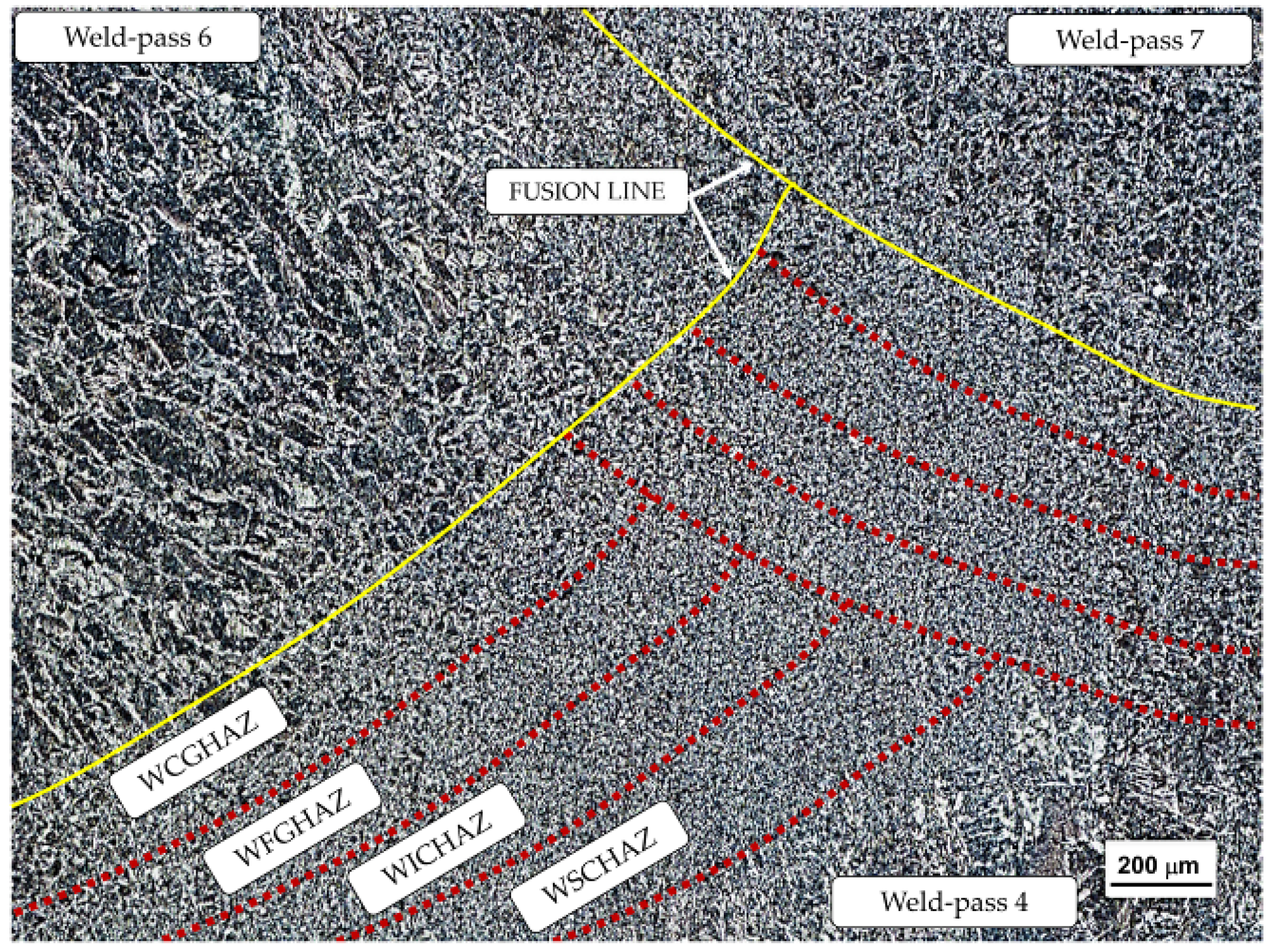
In multi-pass welding, each welding pass causes the alteration of the microstructure of the pre-solidified welded joint portion, resulting in softening. Thus, it is possible to classify the WZ into sub-regions based on the maximum temperature experienced: the Welded Coarse-Grain HAZ (WCGHAZ) (1450–1100 °C), the Welded Fine-Grain HAZ (WFGHAZ) (1100–850 °C), the Welded Inter-Critical HAZ (WICHAZ) (850–700 °C), and the Welded Sub-Critical HAZ (WSCHAZ) (700–500 °C). Figure A1 and Figure A2 show the above-mentioned zones for V-II in the overlap zone between weld passes 6, 7, and 4 (see Figure 2). From Figure A2a, a clear difference between the WCGHAZ and the other zones is visible. The WCGHAZ, which is close to the fusion line, experiences maximum temperatures just below the melting point of the metal. In this region, ALF is observed, together with AF/B and small areas of PF. As is known, dislocated phases (bainite, acicular ferrite, etc.) predominate in the WCGHAZ where the rapid cooling rate does not favor diffusive phenomena. On the contrary, in the WFGHAZ, WICHAZ, and WSCHAZ, Polygonal ferrite prevails, with some islands of fine Pearlite.
Figure A1. Classification of the reheated WZ microstructures of multi-pass welding.
Metals 15 01127 g0a1
Figure A2. Microstructure of the reheated WZ via Nital-2% etching: (a) WCGHAZ, (b) WFGHAZ (c) WICHAZ, and (d) WSCHAZ.
Metals 15 01127 g0a2

Appendix B

Microstructural Characterization of the Heat-Affected Zone
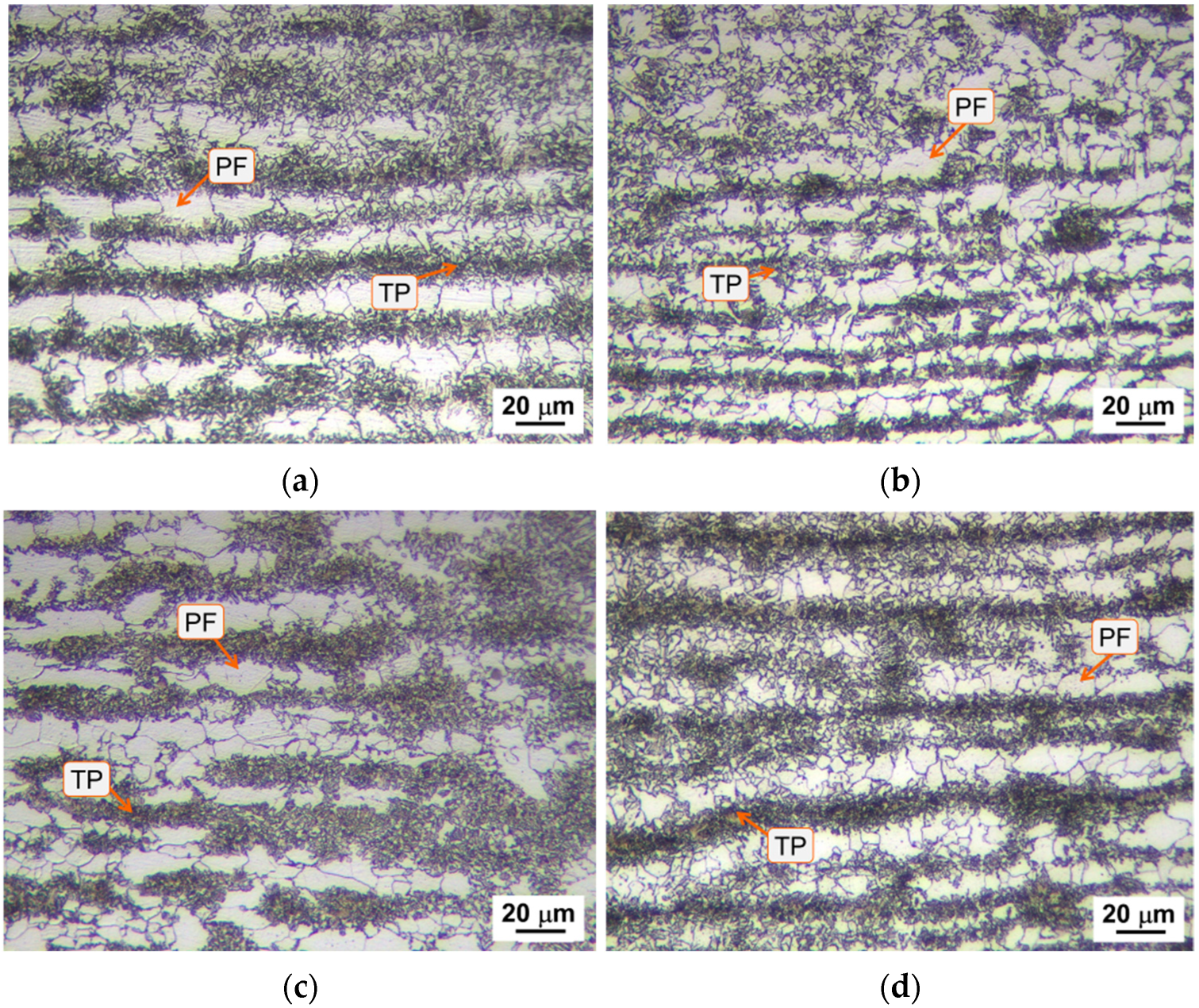
The microstructural results show a presence of heterogeneous microstructural constituents among the different steel variants when going through the different sub-regions of the HAZ of the welded joints. Considering the HAZ according to the thermal cycling undergone, the detailed overview for the four steel variants is shown in Figure A3, Figure A4, Figure A5 and Figure A6.
Figure A3. Microstructure analysis of the SCHAZ: (a) BV, (b) V-I, (c) V-II, and (d) V-III. Images obtained by means of Nital-2% etching.
Metals 15 01127 g0a3
Figure A4. Microstructure analysis of the ICHAZ: (a) BV, (b) V-I, (c) V-II, and (d) V-III. Images obtained by means of Nital-2% and LePerà etching.
Metals 15 01127 g0a4
Figure A5. Microstructure analysis of the CGHAZ: (a) BV, (b) V-I, (c) V-II, and (d) V-III. Images obtained by means of Nital-2% and LePerà etching.
Metals 15 01127 g0a5
Figure A6. Microstructure analysis of the FGHAZ: (a) BV, (b) V-I, (c) V-II, and (d) V-III. Images obtained by means of Nital-2% and LePerà etching.
Metals 15 01127 g0a6

Appendix C

Comparison of Punctual Results from Nanoindentation Tests

This appendix compiles the complete set of point-by-point nanoindentation data obtained for the four profiles detailed in Section 3.2.3 and summarized in Table 5. The tables report the individual values of the maximum indentation depth (hmax), elastic modulus (E), nano-hardness (H), plastic work (WP), elastic work (We), and residual depth after unloading (hf) for every indentation performed in the WZ (profile A), CGHAZ (profile B), and ICCGHAZ with low and high M/A content (profiles C and D, respectively). These detailed datasets complement the average values discussed in the main text and enable complete traceability of the nanoindentation measurements.
Table A1. Nanoindentation results of the WZ (profile A).
hmax *
(µm)
E *
(GPa)
H *
(GPa)
Wp *
(nJ)
We *
(nJ)
hf *
(µm)
11.33186.41.746.54.31.10
21.18170.32.140.35.31.01
31.22164.02.040.14.81.03
41.22166.92.040.54.31.06
51.25168.11.940.35.01.09
* hmax is the maximum indentation depth; E is the elastic modulus; H is the nano-hardness; Wp is the plastic work; We is the elastic work; hf is the residual depth after unloading.
Table A2. Nanoindentation results of the CGHAZ (profile B).
hmax *
(µm)
E *
(GPa)
H *
(GPa)
Wp *
(nJ)
We *
(nJ)
hf *
(µm)
11.19175.02.137.14.81.06
21.23138.12.039.35.01.03
31.18192.22.136.75.01.00
41.22143.12.039.84.71.09
51.20183.02.137.75.21.04
* hmax is the maximum indentation depth; E is the elastic modulus; H is the nano-hardness; Wp is the plastic work; We is the elastic work; hf is the residual depth after unloading.
Table A3. Nanoindentation results of the ICCGHAZ—low M/A (profile C).
hmax *
(µm)
E *
(GPa)
H *
(GPa)
Wp *
(nJ)
We *
(nJ)
hf *
(µm)
11.23141.52.037.95.11.00
21.18141.62.237.25.40.95
31.14167.12.336.65.30.91
41.19166.12.136.95.70.90
* hmax is the maximum indentation depth; E is the elastic modulus; H is the nano-hardness; Wp is the plastic work; We is the elastic work; hf is the residual depth after unloading.
Table A4. Nanoindentation results of the ICCGHAZ—high M/A (profile D).
hmax *
(µm)
E *
(GPa)
H *
(GPa)
Wp *
(nJ)
We *
(nJ)
hf *
(µm)
11.14135.62.333.95.2887.0
21.08184.72.534.55.1857.0
31.06140.12.734.56.2729.0
41.09210.92.537.15.5821.0
* hmax is the maximum indentation depth; E is the elastic modulus; H is the nano-hardness; Wp is the plastic work; We is the elastic work; hf is the residual depth after unloading.

References

  1. Roy, S.; Romualdi, N.; Yamada, K.; Poole, W.; Militzer, M.; Collins, L. The Relationship Between Microstructure and Hardness in the Heat-Affected Zone of Line Pipe Steels. JOM 2022, 74, 2395–2401. [Google Scholar] [CrossRef]
  2. Jindal, S.; Chhibber, R.; Mehta, N.P. Issues in Welding of HSLA Steels. Adv. Mat. Res. 2011, 365, 44–49. [Google Scholar] [CrossRef]
  3. Ceschini, L.; Marconi, A.; Martini, C.; Morri, A.; Di Schino, A. Tensile and Impact Behaviour of a Microalloyed Medium Carbon Steel: Effect of the Cooling Condition and Corresponding Microstructure. Mater. Des. 2013, 45, 171–178. [Google Scholar] [CrossRef]
  4. Di Schino, A.; Di Nunzio, P.E. Effect of Nb Microalloying on the Heat Affected Zone Microstructure of Girth Welded Joints. Mater. Lett. 2017, 186, 86–89. [Google Scholar] [CrossRef]
  5. Di Schino, A. Analysis of Phase Transformation in High Strength Low Alloyed Steels. Metalurgija 2017, 56, 349–352. [Google Scholar]
  6. Di Schino, A.; Guarnaschelli, C. Microstructure and Cleavage Resistance of High Strength Steels. Mater. Sci. Forum 2010, 638–642, 3188–3193. [Google Scholar] [CrossRef]
  7. Liao, W.; Mazánová, V.; Heczko, M.; Hou, W.; Procario, J.; Mills, M.J.; Liu, X. Underlying mechanisms for the effect of Nb micro-alloying on the elemental distribution and precipitation behavior in the X70 weld metal. Materialia 2024, 38, 102264. [Google Scholar] [CrossRef]
  8. Di Schino, A.; Gaggiotti, M.; Testani, C. Heat Treatment Effect on Microstructure Evolution in a 7% Cr Steel for Forging. Metals 2020, 10, 808. [Google Scholar] [CrossRef]
  9. Zhang, Y.; Ma, Y. Research Progress on Titanium–Niobium Micro-Alloyed High-Strength Steel. Materials 2025, 18, 325. [Google Scholar] [CrossRef]
  10. Tian, Y.; Zhao, M.C.; Zeng, Y.P.; Shi, X.B.; Yan, W.; Yang, K.; Zeng, T.Y. Elimination of Primary NbC Carbides in HSLA Steels for Oil Industry Tubular Goods. JOM 2022, 74, 2409–2419. [Google Scholar] [CrossRef]
  11. Ye, Z.; Chen, G.; Wang, W.; Wang, S.; Yang, J.; Huang, J. High-Strength and High-Toughness Weld of S690QL HSLA Steel via a High-Speed High Frequency Electric Cooperated Arc Welding without Additional Heating Measures. Mater. Sci. Eng. A 2023, 880, 145328. [Google Scholar] [CrossRef]
  12. Chen, J.; Shi, Z.; Luo, X.; Chai, F.; Pan, T.; Feng, G.; Yang, C. Micro-Alloying Effects on Microstructure and Weldability of High-Strength Low-Alloy Steel: A Review. Materials 2025, 18, 1036. [Google Scholar] [CrossRef]
  13. Narimani, M.; Hajjari, E.; Eskandari, M.; Szpunar, J.A. Electron Backscattered Diffraction Characterization of S900 HSLA Steel Welded Joints and Evolution of Mechanical Properties. J. Mater. Eng. Perform. 2022, 31, 3985–3997. [Google Scholar] [CrossRef]
  14. Shi, S.C.; Wang, W.C.; Ko, D.K. Influence of Inclusions on Mechanical Properties in Flash Butt Welding Joint of High-Strength Low-Alloy Steel. Metals 2022, 12, 242. [Google Scholar] [CrossRef]
  15. Geng, R.; Li, J.; Shi, C.; Zhi, J.; Lu, B. Effect of Ce on Microstructures, Carbides and Mechanical Properties in Simulated Coarse-Grained Heat-Affected Zone of 800-MPa High-Strength Low-Alloy Steel. Mater. Sci. Eng. A 2022, 840, 142919. [Google Scholar] [CrossRef]
  16. Kumar, V.; Ranjan Sahu, D.; Mandal, A. Parametric Study and Optimization of GMAW Based AM Process for Multi-Layer Bead Deposition. Mater. Today Proc. 2022, 62, 255–261. [Google Scholar] [CrossRef]
  17. Rodriguez-Vargas, B.R.; Stornelli, G.; Hdz-García, H.M.; Miranda Pérez, A.F.; Di Schino, A. Microstructural assessment of ferrite-austenite ratio and its influence on corrosion and mechanical performance of DSS 2205 welds under H2S-rich real environment. Mater. Today Commun. 2025, 47, 113144. [Google Scholar] [CrossRef]
  18. Shukla, P.; Chitral, S.; Kumar, T.; Venkata Kiran, D. The influence of GMAW correction parameters on stabilizing the deposition characteristics for wire arc additive manufacturing. J. Manuf. Process. 2023, 90, 54–68. [Google Scholar] [CrossRef]
  19. Ferreira Filho, D.; Souza, D.; Gonçalves Júnior, J.L.; Reis, R.P.; Da Silva Junior, W.M.; Tavares, A.F. Influence of Substrate on the Tribological Behavior of Inconel 625 GMAW Overlays. Coatings 2023, 13, 1454. [Google Scholar] [CrossRef]
  20. Bettahar, K.; Bouabdallah, M.; Badji, R.; Gaceb, M.; Kahloun, C.; Bacroix, B. Microstructure and Mechanical Behavior in Dissimilar 13Cr/2205 Stainless Steel Welded Pipes. Mater. Des. 2015, 85, 221–229. [Google Scholar] [CrossRef]
  21. Kim, B.C.; Lee, S.; Kim, N.J.; Lee, D.Y. Microstructure and Local Brittle Zone Phenomena in High-Strength Low-Alloy Steel Welds. Metall. Trans. A 1991, 22, 139–149. [Google Scholar] [CrossRef]
  22. Kvackaj, T.; Bidulská, J.; Bidulský, R. Overview of Hss Steel Grades Development and Study of Reheating Condition Effects on Austenite Grain Size Changes. Materials 2021, 14, 1988. [Google Scholar] [CrossRef] [PubMed]
  23. Prasad, K.; Dwivedi, D.K. Some Investigations on Microstructure and Mechanical Properties of Submerged Arc Welded HSLA Steel Joints. Int. J. Adv. Manuf. Technol. 2008, 36, 475–483. [Google Scholar] [CrossRef]
  24. Davis, C.L.; King, J.E. Cleavage Initiation in the Intercritically Reheated Coarse-Grained Heat-Affected Zone: Part I. Fractographic Evidence. Metall. Mater. Trans. A 1994, 25, 563–573. [Google Scholar] [CrossRef]
  25. Akselsen, O.M.; Grong, Ø.; Solberg, J.K. Structure–Property Relationships in Intercritical Heat Affected Zone of Low-Carbon Microalloyed Steels. Mater. Sci. Technol. 1987, 3, 649–655. [Google Scholar] [CrossRef]
  26. Qiu, H.; Mori, H.; Enoki, M.; Kishi, T. Fracture Mechanism and Toughness of the Welding Heat-Affected Zone in Structural Steel under Static and Dynamic Loading. Metall. Mater. Trans. A 2000, 31, 2785–2791. [Google Scholar] [CrossRef]
  27. Boniszewski, T.; Keeler, T. HAZ Hardness Control in C-Mn Microalloyed Structural Steels. Met. Constr. 1984, 16, 608–617. [Google Scholar]
  28. Schofield, R.; Weiner, R.T. Simulating HAZ Toughness in Pipeline Steels. Met. Constr. Br. Weld. J. 1974, 6, 45–47. [Google Scholar]
  29. Ouchi, C. Advances in Physical Metallurgy and Processing of Steels. Development of Steel Plates by Intensive Use of TMCP and Direct Quenching Processes. ISIJ Int. 2001, 41, 542–553. [Google Scholar] [CrossRef]
  30. Zhang, H.; Deng, Y.; Chen, F.; Luo, Y.; Xiao, X.; Lu, N.; Liu, Y.; Deng, Y. Fatigue life prediction for orthotropic steel bridge decks welds using a Gaussian variational bayes network and small sample experimental data. Reliab. Eng. Syst. Saf. 2025, 264, 111406. [Google Scholar] [CrossRef]
  31. Zhang, H.; Zhao, L.; Yang, S.; Deng, Y.; Ouyang, Z. Fatigue evaluation of Orthotropic steel deck welds based on WIM data and UD-BP neural network. Structures 2025, 78, 109198. [Google Scholar] [CrossRef]
  32. Zhang, H.; Deng, Y.; Cao, Y.; Chen, F.; Luo, Y.; Xiao, X.; Deng, Y.; Liu, Y. Field testing, analytical, and numerical assessments on the fatigue reliability on bridge suspender by considering the coupling effect of multiple pits. Struct. Infrastruct. Eng. 2025, 1–16. [Google Scholar] [CrossRef]
  33. Bonnevie, E.; Ferrière, G.; Ikhlef, A.; Kaplan, D.; Orain, J.M. Morphological Aspects of Martensite–Austenite Constituents in Intercritical and Coarse Grain Heat Affected Zones of Structural Steels. Mater. Sci. Eng. A 2004, 385, 352–358. [Google Scholar] [CrossRef]
  34. Stornelli, G.; Tselikova, A.; Mirabile Gattia, D.; Mortello, M.; Schmidt, R.; Sgambetterra, M.; Testani, C.; Zucca, G.; Di Schino, A. Influence of Vanadium Micro-Alloying on the Microstructure of Structural High Strength Steels Welded Joints. Materials 2023, 16, 2897. [Google Scholar] [CrossRef] [PubMed]
  35. Li, Y.; Crowther, D.N.; Green, M.J.W.; Mitchell, P.S.; Baker, T.N. The Effect of Vanadium and Niobium on the Properties and Microstructure of the Intercritically Reheated Coarse Grained Heat Affected Zone in Low Carbon Microalloyed Steels. ISIJ Int. 2001, 41, 46–55. [Google Scholar] [CrossRef]
  36. Taillard, R.; Verrier, P.; Maurickx, T.; Foct, J. Effect of Silicon on CGHAZ Toughness and Microstructure of Microalloyed Steels. Metall. Mater. Trans. A 1995, 26, 447–457. [Google Scholar] [CrossRef]
  37. Jang, J.; Lee, J.-S.; Ju, J.-B.; Lee, B.-W.; Kwon, D.; Kim, W.-S. Determination of Microstructural Criterion for Cryogenic Toughness Variation in Actual HAZs Using Microstructure-Distribution Maps. Mater. Sci. Eng. A 2003, 351, 183–189. [Google Scholar] [CrossRef]
  38. Jang, J.-I.; Lee, B.-W.; Ju, J.-B.; Kwon, D.; Kim, W.-S. Crack-Initiation Toughness and Crack-Arrest Toughness in Advanced 9 Pct Ni Steel Welds Containing Local Brittle Zones. Metall. Mater. Trans. A 2002, 33, 2615–2622. [Google Scholar] [CrossRef]
  39. Li, C.; Wang, Y.; Chen, Y. Influence of Peak Temperature during In-Service Welding of API X70 Pipeline Steels on Microstructure and Fracture Energy of the Reheated Coarse Grain Heat-Affected Zones. J. Mater. Sci. 2011, 46, 6424–6431. [Google Scholar] [CrossRef]
  40. Ju, J.-B.; Kim, W.; Jang, J. Variations in DBTT and CTOD within Weld Heat-Affected Zone of API X65 Pipeline Steel. Mater. Sci. Eng. A 2012, 546, 258–262. [Google Scholar] [CrossRef]
  41. Bertolo, V.; Jiang, Q.; Terol Sanchez, M.; Riemslag, T.; Walters, C.L.; Sietsma, J.; Popovich, V. Cleavage Fracture Micromechanisms in Simulated Heat Affected Zones of S690 High Strength Steels. Mater. Sci. Eng. A 2023, 868, 144762. [Google Scholar] [CrossRef]
  42. Mohseni, P.; Solberg, J.K.; Karlsen, M.; Akselsen, O.M.; Østby, E. Investigation of Mechanism of Cleavage Fracture Initiation in Intercritically Coarse Grained Heat Affected Zone of HSLA Steel. Mater. Sci. Technol. 2012, 28, 1261–1268. [Google Scholar] [CrossRef]
  43. Lee, S.G.; Kim, B.; Sohn, S.S.; Kim, W.G.; Um, K.-K.; Lee, S. Effects of Local-Brittle-Zone (LBZ) Microstructures on Crack Initiation and Propagation in Three Mo-Added High-Strength Low-Alloy (HSLA) Steels. Mater. Sci. Eng. A 2019, 760, 125–133. [Google Scholar] [CrossRef]
  44. Li, Y.; Baker, T.N. Effect of Morphology of Martensite–Austenite Phase on Fracture of Weld Heat Affected Zone in Vanadium and Niobium Microalloyed Steels. Mater. Sci. Technol. 2010, 26, 1029–1040. [Google Scholar] [CrossRef]
  45. Bayraktar, E.; Kaplan, D. Mechanical and Metallurgical Investigation of Martensite–Austenite Constituents in Simulated Welding Conditions. J. Mater. Process. Technol. 2004, 153–154, 87–92. [Google Scholar] [CrossRef]
  46. Kumar, S.; Nath, S.K. Effect of Weld Thermal Cycles on Microstructures and Mechanical Properties in Simulated Heat Affected Zone of a HY 85 Steel. Trans. Indian Inst. Met. 2017, 70, 239–250. [Google Scholar] [CrossRef]
  47. Zhang, P.; Laleh, M.; Hughes, A.E.; Marceau, R.K.W.; Hilditch, T.; Tan, M.Y. Effect of Microstructure on Hydrogen Embrittlement and Hydrogen-Induced Cracking Behaviour of a High-Strength Pipeline Steel Weldment. Corros. Sci. 2024, 227, 111764. [Google Scholar] [CrossRef]
  48. Hausmann, K.; Krizan, D.; Spiradek-Hahn, K.; Pichler, A.; Werner, E. The Influence of Nb on Transformation Behavior and Mechanical Properties of TRIP-Assisted Bainitic–Ferritic Sheet Steels. Mater. Sci. Eng. A 2013, 588, 142–150. [Google Scholar] [CrossRef]
  49. Yu, H.; Wu, K.; Dong, B.; Yu, L.; Liu, J.; Liu, Z.; Xiao, D.; Jing, X.; Liu, H. Effect of Niobium Content on the Microstructure and Mechanical Properties of Simulated Coarse-Grained Heat-Affected Zone (CGHAZ) of High-Strength Low-Alloy (HSLA) Steels. Materials 2022, 15, 3318. [Google Scholar] [CrossRef]
  50. Mitchell, P.S.; Hart, P.H.M.; Morrison, W.B. The Effect of Microalloying on HAZ Toughness. In Proceedings of the International Conference Microalloying, Pittsburgh, PA, USA, 10–12 September 1995; pp. 149–162. [Google Scholar]
  51. Cui, J.; Zhu, W.; Chen, Z.; Chen, L. Microstructural Characteristics and Impact Fracture Behaviors of a Novel High-Strength Low-Carbon Bainitic Steel with Different Reheated Coarse-Grained Heat-Affected Zones. Metall. Mater. Trans. A Phys. Metall. Mater. Sci. 2020, 51, 6258–6268. [Google Scholar] [CrossRef]
  52. Benz, J. The Effect of Vanadium and Other Microalloying Elements on the Microstructure and Properties of Bainitic HSLA Steels. Mater. Sci. Technol. Conf. Exhib. 2017, 1, 490. [Google Scholar]
  53. Fazeli, F.; Amirkhiz, B.S.; Scott, C.; Arafin, M.; Collins, L. Kinetics and Microstructural Change of Low-Carbon Bainite Due to Vanadium Microalloying. Mater. Sci. Eng. A 2018, 720, 248–256. [Google Scholar] [CrossRef]
  54. Baker, T.N. Microalloyed Steels. Ironmak. Steelmak. 2016, 43, 264–307. [Google Scholar] [CrossRef]
  55. Sun, W.; Wang, G.; Zhang, J.; Xia, D. Microstructure Transformation Behaviour of 610 MPa HSLA Steel Plate for 150000 M3 Oil Storage Tank Construction. J. Iron Steel Res. Int. 2010, 17, 48–52. [Google Scholar] [CrossRef]
  56. Baker, T.N. Processes, Microstructure and Properties of Vanadium Microalloyed Steels. Mater. Sci. Technol. 2009, 25, 1083–1107. [Google Scholar] [CrossRef]
  57. Wu, H.; Xia, D.; Ma, H.; Du, Y.; Gao, C.; Gao, X.; Du, L. Study on Microstructure Characterization and Impact Toughness in the Reheated Coarse-Grained Heat Affected Zone of V-N Microalloyed Steel. J. Mater. Eng. Perform. 2022, 31, 376–382. [Google Scholar] [CrossRef]
  58. Kalantar, M.; Najafi, H.; Afshar, M.R. Comparison Between Vanadium and Niobium Effects on the Mechanical Properties of Intercritically Heat Treated Microalloyed Cast Steels. Met. Mater. Int. 2019, 25, 229–237. [Google Scholar] [CrossRef]
  59. Chen, Y. Microstructure and mechanical property development in the simulated heat affected zone of v treated HSLA steels. Acta Metall. Sin. 2006, 19, 57–67. [Google Scholar] [CrossRef]
  60. Miletić, I.; Ilić, A.; Nikolić, R.R.; Ulewicz, R.; Ivanović, L.; Sczygiol, N. Analysis of Selected Properties of Welded Joints of the HSLA Steels. Materials 2020, 13, 1301. [Google Scholar] [CrossRef]
  61. Cho, L.; Tselikova, A.; Holtgrewe, K.; De Moor, E.; Schmidt, R.; Findley, K.O. Critical Assessment 42: Acicular Ferrite Formation and Its Influence on Weld Metal and Heat-Affected Zone Properties of Steels. Mater. Sci. Technol. 2022, 38, 1425–1433. [Google Scholar] [CrossRef]
  62. Hernandez-Flores, J.E.; Rodriguez-Vargas, B.R.; Stornelli, G.; Pérez, A.F.M.; de García-Vázquez, F.J.; Gómez-Casas, J.; Di Schino, A. Evaluation of Austenitic Stainless Steel ER308 Coating on H13 Tool Steel by Robotic GMAW Process. Metals 2023, 14, 43. [Google Scholar] [CrossRef]
  63. Hunkel, M. Segregations in Steels during Heat Treatment—A Consideration along the Process Chain. HTM J. Heat Treat. Mater. 2021, 76, 79–104. [Google Scholar] [CrossRef]
  64. ASTM E3-11; Standard Guide for Preparation of Metallographic Specimens. ASTM International: West Conshohocken, PA, USA, 2011.
  65. LePera, F.S. Improved Etching Technique for the Determination of Percent Martensite in High-Strength Dual-Phase Steels. Metallography 1979, 12, 263–268. [Google Scholar] [CrossRef]
  66. ISO 6892-1:2019; Metallic Materials—Tensile Testing Part 1: Method of Test at Room Temperature. ISO: Geneva, Switzerland, 2019.
  67. DuPont, J.N.; Babu, S.; Liu, S. Welding of Materials for Energy Applications. Metall. Mater. Trans. A 2013, 44, 3385–3410. [Google Scholar] [CrossRef]
  68. Yang, Y.-P. Recent Advances in the Prediction of Weld Residual Stress and Distortion—Part 2. Weld. J. 2021, 100, 193–205. [Google Scholar] [CrossRef]
  69. Sindo, K. Welding Metallurgy, 3rd ed.; Wiley: Hoboken, NJ, USA, 2021; ISBN 978-1-119-52481-6. [Google Scholar]
  70. Lancaster, J.F. Metallurgy of Welding, 6th ed.; Paperback; Woodhead: Cambridge, UK, 1999; ISBN 9781855734289. [Google Scholar]
  71. Amin, S.A.; Marhoon, I.I.; Kattab, D.A.A.N.; Eleiwi, M.A.; Majdi, H.S.; Habeeb, L.J. Experimental and numerical investigating of heat input effects in gas metal arc welding and shielded metal arc welding: A detailed comparison of welded alloy steel properties. Math. Model. Eng. Probl. 2025, 12, 2351–2361. [Google Scholar] [CrossRef]
  72. Anandavijayan, S.; Mehmanparast, A.; Braithwaite, J.; Brennan, F.; Chahardehi, A. Material pre-straining effects on fatigue behaviour of S355 structural steel. J. Constr. Steel Res. 2021, 183, 106707. [Google Scholar] [CrossRef]
  73. Tomków, J.; Rogalski, G.; Fydrych, D.; Łabanowski, J. Improvement of S355G10+N Steel Weldability in Water Environment by Temper Bead Welding. J. Mater. Process. Technol. 2018, 262, 372–381. [Google Scholar] [CrossRef]
  74. Tomków, J.; Rogalski, G.; Fydrych, D.; Łabanowski, J. Advantages of the Application of the Temper Bead Welding Technique During Wet Welding. Materials 2019, 12, 915. [Google Scholar] [CrossRef]
  75. Serrano, R.; Ambriz, R.R.; Ayoub, G.; Jaramillo, D. Mechanical Behavior of Armor Steel Gas Metal Arc Welding Joints Performed by Nickel-Chromium and Low-Alloy Steel Filler Metals. J. Mater. Eng. Perform. 2022, 31, 3930–3942. [Google Scholar] [CrossRef]
  76. Ghosh, P.K. Introduction to Gas Metal Arc Welding Process; Springer: Singapore, 2017. [Google Scholar]
  77. Mičian, M.; Winczek, J.; Gucwa, M.; Koňár, R.; Málek, M.; Postawa, P. Investigation of Welds and Heat Affected Zones in Weld Surfacing Steel Plates Taking into Account the Bead Sequence. Materials 2020, 13, 5666. [Google Scholar] [CrossRef] [PubMed]
  78. Gao, W.; Wang, D.; Cheng, F.; Di, X.; Deng, C.; Xu, W. Microstructural and Mechanical Performance of Underwater Wet Welded S355 Steel. J. Mater. Process. Technol. 2016, 238, 333–340. [Google Scholar] [CrossRef]
  79. Thewlis, G. Weldability of X100 Linepipe. Sci. Technol. Weld. Join. 2000, 5, 365–377. [Google Scholar] [CrossRef]
  80. Thewlis, G.; Whiteman, J.A.; Senogles, D.J. Dynamics of Austenite to Ferrite Phase Transformation in Ferrous Weld Metals. Mater. Sci. Technol. 1997, 13, 257–274. [Google Scholar] [CrossRef]
  81. Thewlis, G. Classification and Quantification of Microstructures in Steels. Mater. Sci. Technol. 2004, 20, 143–160. [Google Scholar] [CrossRef]
  82. Sinha, M.; Yadav, S.; Ghosh, S. A novel observation of Widmanstätten ferrite and pearlite by thermo-mechanical processing of interstitial-free steel. Mater. Manuf. Process. 2022, 37, 1766–1771. [Google Scholar] [CrossRef]
  83. Leont’ev, B.A.; Buzovskii, Y.N. Mechanical properties of steel with a Widmanstatten structure. Met. Sci. Heat Treat. 1968, 10, 930–932. [Google Scholar] [CrossRef]
  84. Otterberg, R.; Sandström, R.; Sandberg, A. Influence of Widmanstätten ferrite on mechanical properties of microalloyed steels. Met. Technol. 1980, 7, 397–408. [Google Scholar] [CrossRef]
  85. Zhu, Z.; Kuzmikova, L.; Li, H.; Barbaro, F. Effect of Inter-Critically Reheating Temperature on Microstructure and Properties of Simulated Inter-Critically Reheated Coarse Grained Heat Affected Zone in X70 Steel. Mater. Sci. Eng. A 2014, 605, 8–13. [Google Scholar] [CrossRef]
  86. Vishnu, P.R. Solid-State Transformations in Weldments. In Welding, Brazing, and Soldering; ASM International: Materials Park, OH, USA, 1993; pp. 70–87. [Google Scholar]
  87. Babu, S.S.; Bhadeshia, H.K.D.H. A Direct Study of Grain Boundary Allotriomorphic Ferrite Crystallography. Mater. Sci. Eng. A 1991, 142, 209–219. [Google Scholar] [CrossRef]
  88. Babu, S.S. The Mechanism of Acicular Ferrite in Weld Deposits. Curr. Opin. Solid State Mater. Sci. 2004, 8, 267–278. [Google Scholar] [CrossRef]
  89. Sarma, D.S.; Karasev, A.V.; Jönsson, P.G. On the Role of Non-Metallic Inclusions in the Nucleation of Acicular Ferrite in Steels. ISIJ Int. 2009, 49, 1063–1074. [Google Scholar] [CrossRef]
  90. Guo, H.; Bai, Y.; Yang, S.W.; He, X.L. Nucleation of Bainite on Allotriomorphic Ferrite/Austenite Interface in a Low Carbon Steel. Mater. Sci. Forum 2010, 654–656, 2326–2329. [Google Scholar] [CrossRef]
  91. Lee, T.-K.; Kim, H.J.; Kang, B.Y.; Hwang, S.K. Effect of Inclusion Size on the Nucleation of Acicular Ferrite in Welds. ISIJ Int. 2000, 40, 1260–1268. [Google Scholar] [CrossRef]
  92. Furuhara, T.; Yamaguchi, J.; Sugita, N.; Miyamoto, G.; Maki, T. Nucleation of Proeutectoid Ferrite on Complex Precipitates in Austenite. ISIJ Int. 2003, 43, 1630–1639. [Google Scholar] [CrossRef]
  93. Jones, S.J.; Bhadeshia, H.K.D.H. Competitive Formation of Inter- and Intragranularly Nucleated Ferrite. Metall. Mater. Trans. A 1997, 28, 2005–2013. [Google Scholar] [CrossRef]
  94. Garcia, C.; Cornide, J.; Capdevila, C.; Caballero, F.G.; de Andrés, C.G. Influence of V Precipitates on Acicular Ferrite Transformation Part 2: Transformation Kinetics. ISIJ Int. 2008, 48, 1276–1279. [Google Scholar] [CrossRef]
  95. Babu, S.S.; David, S.A. Inclusion Formation and Microstructure Evolution in Low Alloy Steel Welds. ISIJ Int. 2002, 42, 1344–1353. [Google Scholar] [CrossRef]
  96. Garcia-Mateo, C.; Capdevila, C.; Caballero, F.G.; de Andrés, C.G. Influence of V Precipitates on Acicular Ferrite Transformation Part 1: The Role of Nitrogen. ISIJ Int. 2008, 48, 1270–1275. [Google Scholar] [CrossRef]
  97. Barbaro, F.J.; Krauklis, P.; Easterling, K.E. Formation of Acicular Ferrite at Oxide Particles in Steels. Mater. Sci. Technol. 1989, 5, 1057–1068. [Google Scholar] [CrossRef]
  98. Zhang, J.; Xin, W.; Luo, G.; Wang, R.; Meng, Q.; Xian, S. Effect of Welding Heat Input on Microstructural Evolution, Precipitation Behavior and Resultant Properties of the Simulated CGHAZ in High-N V-Alloyed Steel. Mater. Charact. 2020, 162, 110201. [Google Scholar] [CrossRef]
  99. Hu, J.; Du, L.-X.; Wang, J.-J.; Gao, C.-R. Effect of Welding Heat Input on Microstructures and Toughness in Simulated CGHAZ of V–N High Strength Steel. Mater. Sci. Eng. A 2013, 577, 161–168. [Google Scholar] [CrossRef]
  100. Loder, D.; Michelic, S.K.; Bernhard, C. Acicular Ferrite Formation and Its Influencing Factors-A Review. J. Mater. Sci. Res. 2016, 6, 24. [Google Scholar] [CrossRef]
  101. Capdevila, C.; García-Mateo, C.; Chao, J.; Caballero, F.G. Effect of V and N Precipitation on Acicular Ferrite Formation in Sulfur-Lean Vanadium Steels. Metall. Mater. Trans. A 2009, 40, 522–538. [Google Scholar] [CrossRef]
  102. He, K.; Edmonds, D.V. Formation of Acicular Ferrite and Influence of Vanadium Alloying. Mater. Sci. Technol. 2002, 18, 289–296. [Google Scholar] [CrossRef]
  103. Ishikawa, F.; Takahashi, T.; Ochi, T. Intragranular Ferrite Nucleation in Medium-Carbon Vanadium Steels. Metall. Mater. Trans. A 1994, 25, 929–936. [Google Scholar] [CrossRef]
Figure 1. Microstructure of the BM after Nital-2% etching: (a) BV, (b) V-I, (c) V-II, and (d) V-III.
Metals 15 01127 g001
Figure 2. Schematic view of the joint.
Metals 15 01127 g002
Figure 3. (a) Positioning of thermocouples A1, A2, and A3 on the welded bead of V-II. (b) The thermal profile acquired during welding.
Metals 15 01127 g003
Figure 4. Scheme of the hardness profile in the (a) upper zone and (b) ICCGHAZ of the welded joints.
Metals 15 01127 g004
Figure 5. Schematic drawing of the samples used for tensile tests.
Metals 15 01127 g005
Figure 6. Macrostructure of the cross-sections of the weld joints: (a) BV, (b) V-I, (c) V-II, and (d) V-III.
Metals 15 01127 g006
Figure 7. Microstructure analysis of the WZ of V-II. Images obtained by means of (a) Nital-2% and (b) LePerà etching.
Metals 15 01127 g007
Figure 8. Scheme of the Heat-Affected Zone (HAZ) in a multi-pass welding.
Metals 15 01127 g008
Figure 9. Microstructure analysis of the HAZ of V-II: (a) SCHAZ, (b) ICHAZ, (c) CGHAZ, and (d) FGHAZ. Images obtained by means of Nital-2% and LePerà etching.
Metals 15 01127 g009
Figure 10. Macrographic identification of the ICCGHAZ in V-I.
Metals 15 01127 g010
Figure 11. Micrographic analysis of the ICCHHAZ: (a) BV, (b) V-I, (c) V-II, and (d) V-III. Images obtained by means of Nital-2% and LePerà etching.
Metals 15 01127 g011
Figure 12. Optical micrographs of the ICCGHAZ in the V-I. The arrows indicate the MA constituent in the lamellar (M/AL) and granular (M/AG) forms.
Metals 15 01127 g012
Figure 13. TEM micrographs of micro-alloyed steel variants in the ICCGHAZ.
Metals 15 01127 g013
Figure 14. (a) Vickers hardness (HV1) profile at the upper part and (b) on the ICCGHAZ of the welded joints of the BV, V-I, V-II, and V-III.
Metals 15 01127 g014
Figure 15. Nanoindentation profiles in the WZ, CGHAZ, and ICCGHAZ of V-II.
Metals 15 01127 g015
Figure 16. Welded samples after the tensile test.
Metals 15 01127 g016
Figure 17. Distribution of V and C (wt.%) in the phases of BV and V-II as a function of the temperature. Graph obtained by JMatPro simulations.
Metals 15 01127 g017
Table 1. Chemical composition of the BM and filler metal (wt.%) (Fe to balance).
CMnVSiNb
Base Variant-(S355) (BV)0.161.45-0.03-
Variant I (V-I)0.161.450.050.03-
Variant II (V-II)0.161.450.100.03-
Variant III (V-III)0.161.450.030.030.02
ER70S-60.081.45-0.90-
Table 2. Welding operating parameters employed for the four steel variants.
Weld-PassCurrent (A)Voltage (V)Welding Speed (mm/min)Wire Feed Speed (mm/s)Heat Input (kJ/mm)
1125–13516–17170–1904000.51–0.65
2165–175210–2303800.59–0.72
3175–18517–18230–2504500.57–0.67
4175–185220–2404500.60–0.73
5180–190310–3304800.45–0.53
6180–190390–4105000.36–0.42
7180–190390–4105000.36–0.42
Arc length: 15–25 mm; welding position: 1 G; and multi-pass welding with an inter-pass temperature of 250 °C.
Table 3. Fraction of the M/A (%) constituent present in the ICCGHAZ.
Base VariantVariant IVariant IIVariant III
M/A fraction (%)8.96.45.45.8
Table 4. Composition (wt.%) of only V-rich and Nb-rich precipitates indicated in Figure 13, as determined by EDS.
VNbFeMnSi
Variant I (low V)89.9 ± 0.2-8.0 ± 0.20.3 ± 0.11.8 ± 0.1
Variant II (high V)80.4 ± 0.2-16.9 ± 0.20.9 ± 0.11.8 ± 0.1
Variant III (V and Nb)33.5 ± 0.246.2 ± 0.218.7 ± 0.20.2 ± 0.11.4 ± 0.1
Table 5. Mechanical properties by nanoindentation profiles in the WZ, CGHAZ, and ICCGHAZ of V-II.
hmax *
(µm)
E *
(GPa)
H *
(GPa)
Wp *
(nJ)
We *
(nJ)
hf *
(µm)
Profile A
(WZ)
1.24 ± 0.05171.1 ± 8.81.9 ± 0.241.5 ± 2.8 4.7 ± 0.41.06 ± 0.04
Profile B
(CGHAZ)
1.20 ± 0.02166.3 ± 24.32.1 ± 0.138.1 ± 1.44.9 ± 0.21.04 ± 0.03
Profile C
(ICCGHAZ—low M/A)
1.19 ± 0.04154.1 ± 14.52.1 ± 0.137.1 ± 0.65.4 ± 0.30.94 ± 0.05
Profile D
(ICCGHAZ—high M/A)
1.09 ± 0.03167.8 ± 36.32.5 ± 0.135.0 ± 1.45.5 ± 0.50.82 ± 0.07
* hmax is the maximum indentation depth; E is the elastic modulus; H is the nano-hardness; Wp is the plastic work; We is the elastic work; hf is the residual depth after unloading.
Table 6. Tensile test results.
YS * (MPa)UTS * (MPa)YS/UTSAU * (%)A * (%)Breaking Zone
Base Variant360 ± 14567 ± 210.629.2 ± 1.748.3 ± 1.9Base metal
Variant I428 ± 20579 ± 280.727.4 ± 1.346.7 ± 0.6Base metal
Variant II410 ± 24575 ± 280.731.0 ± 0.850.3 ± 1.5Base metal
Variant III415 ± 19578 ± 230.730.0 ± 1.146.1 ± 1.2Base metal
* YS is the yield stress; UTS is the ultimate tensile stress; AU is uniform elongation; A is total elongation.
Table 7. Solubilization temperature of elements V and Nb in the steel variants V-I, V-II, and V-III.
ElementSolubilization Temperature (°C)
V in V-I770 °C
V in V-II820 °C
V in V-III1150 °C
Nb in V-III1150 °C
Table 8. Indicative parameters of the local mechanical behavior of the HAZ sub-areas, obtained from nanoindentation tests.
I P *H/E *H/E2 * K e *
WZ0.890.0116·10−50.15
CGHAZ0.880.0138·10−50.14
ICCGHAZ—low M/A0.870.0148·10−50.21
ICCGHAZ—high M/A0.860.0159·10−50.24
* IP is the plasticity index; H/E is the correlation used to evaluate the dissipation of elastic energy; H/E2 is the correlation used to evaluate the dissipation of plastic energy; K e is the elastic recovery coefficient.
Disclaimer/Publisher’s Note: The statements, opinions and data contained in all publications are solely those of the individual author(s) and contributor(s) and not of MDPI and/or the editor(s). MDPI and/or the editor(s) disclaim responsibility for any injury to people or property resulting from any ideas, methods, instructions or products referred to in the content.