Article

Microstructure Evolution of a TRIP Fe–1.4Si–2.6Mn–0.17C Steel After Intercritical Treating and Its Effect on Mechanical Properties

by
Valeria Miranda-Lopez
,
Manuel Alejandro Beltrán-Zúñiga
,
Victor M. Lopez-Hirata
,
Hector J. Dorantes-Rosales
and
Maribel L. Saucedo-Muñoz
*
Instituto Politecnico Nacional (ESIQIE), Ciudad de México 07300, Mexico
*
Author to whom correspondence should be addressed.
Metals 2025, 15(10), 1096; https://doi.org/10.3390/met15101096
Submission received: 8 September 2025 / Revised: 26 September 2025 / Accepted: 29 September 2025 / Published: 1 October 2025

Abstract

This work studied microstructure evolution during the intercritical treatment of Fe–1.4Si–2.6Mn–0.17C TRIP steel. Steel specimens were heated in the intercritical region, α ferrite and γ austenite phases, at 750 °C for 30 min, water-quenched, air-cooled, and austempered at 350 °C for 30 min. Microstructural analysis was performed by optical microscopy, scanning electron microscopy, and X-ray diffraction. All heat-treated specimens were mechanically characterized by uniaxial tension and Vickers hardness tests. Thermo-Calc software 2024b was used to analyze the microstructure and phases of heat-treated steel. The microstructural characterization results revealed that the phases and microconstituents were ferrite, austenite, cementite, pearlite, and retained austenite. Thermo-Calc results were consistent with the phases and microconstituents identified for each heat-treatment condition. On the other hand, the tension test results showed that the yield strength and ultimate tensile strength ranged between 690 and 820 MPa and 1190–1255 MPa, respectively, for these heat-treated steels. Likewise, Thermo-Calc proved to be a powerful tool for designing intercritical heat treatments for TRIP steels.

Graphical Abstract

1. Introduction

The development of Advanced High-Strength Steels AHSS is mainly focused on improving their mechanical strength that can lighten the weight of the automotive body, thus increase passenger safety and fuel efficiency, and decrease emission levels of engines [1,2,3,4]. The designation AHSS includes dual-phase (DP), transformation-induced by plasticity (TRIP), complex-phase (CP) and martensitic (M) steels. These steels are characterized by yield strength higher than 300 MPa and a tensile strength higher than 600 MPa with 20% elongation and a reduction in structural weight of up to 20% [1,2]. A combination of strength and formability characterizes AHSS. This fact enabled the use of high-strength steels in a much wider range of applications [1,2,5]. High-strength steel grades with a high energy absorption potential correspond to typical DP and TRIP steel grades, which have tensile strengths exceeding 1000 MPa, under dynamic loading that occurs during vehicle crashes or collisions. That is, it is essential to evaluate the effect of heat treatments of AHSS on the microstructure evolution, which enables us to obtain the desired mechanical properties. Intercritical treatment is a common practice used to achieve good mechanical properties. Additionally, the design of heat treatments can be performed using CALPHAD-based methods [6,7,8], which could permit carrying out the heat treatments of these steels to improve their mechanical properties.
Some TRIP steels are heat-treated by austempering, which follows the intercritical α + γ phase annealing of low-alloy Si-bearing medium-C, 0.12–0.55%, steels [5,9]. During intercritical annealing, carbon partitioning between ferrite and austenite increases the austenite carbon content to 0.3–0.4 wt. %. After intercritical annealing, the steel is quenched to a bainitic transformation temperature and isothermally held for several minutes. A high cooling rate (exceeding 30 °C/s) between the two annealing stages is needed to suppress the formation of ferrite or pearlite. The initial cooling rate may be lower when the temperature is still higher than the A1 critical temperature, which allows further enrichment of the austenite with carbon [9,10,11,12]. The main attributes of TRIP steels are their combination of high strength and ductility, as well as hardness, which is enhanced by the transformation of the retained austenite during plastic deformation when an impact occurs [5,6,7,8,9,10,11].
TRIP steels may reach a maximum of 15 vol. % retained austenite by volume following a bainitic transformation [5,7]. Achieving the optimal volume fraction of retained austenite, as well as appropriate amounts of other constituents such as ferrite, bainite, and martensite, requires partial austenitization and subsequent isothermal quenching for bainitic transformation [5,13].
The use of CALPHAD-based software, such as Thermo-Calc, is a suitable alternative for analyzing the phase transformations of this steel during heat treatment and assessing their effect on microstructure evolution and mechanical properties [6,7,8]. Thermo-Calc is a central part of Integrated Computational Materials Engineering (ICME), a systems-based approach to product design and manufacturing that connects materials and processing models into an integrated framework [14]. It enables the determination of phases and microconstituents under both equilibrium and nonequilibrium conditions and it can assist in the design of intercritical heat treatments by providing transformation diagrams and property predictions relevant to these processes. Similar approaches have been reported in recent studies combining CALPHAD-based simulations with advanced experimental techniques to validate predictions in medium-Mn AHSS. These include the evaluation of retained austenite stability using SEM, EBSD, XRD, and dilatometry, with results compared to thermodynamic Ms model calculations [15]; the use of in situ high-energy X-ray diffraction during intercritical annealing, integrated with DICTRA diffusion simulations to monitor austenite fraction evolution and solute partitioning [16]; in situ synchrotron X-ray diffraction coupled with microstructure-based micromechanical modeling to analyze the evolution, internal stresses, and stability of retained austenite in TRIP-aided steels [17]; and dilatometric studies of phase transformations in non-deformed and plastically deformed medium-Mn multiphase steels, relating transformation temperatures and kinetics to thermodynamic predictions [18]. These integrated approaches highlight the value of validating CALPHAD-based predictions through complementary experimental techniques. Furthermore, Thermo-Calc can help to design the heat treatments and to understand the microstructure evolution in TRIP steels. That is, Thermo-Calc is an alternative to the trial-and-error method used for the heat treatment design.
Thus, the present work aims to experimentally characterize the microstructural evolution of a TRIP Fe−1.39Si−2.57Mn−0.17C steel during different heat treatment and its effect on mechanical properties. Additionally, it explores the application of Thermo-Calc to the heat treatment design and the microstructure and mechanical properties prediction.

2. Materials and Methods

2.1. Numerical Methodology

Thermo-Calc, TC, software [19] was used to evaluate the stability of phases in the TRIP steel. The Time-Temperature-Transformation TTT diagram was calculated using the Steel Model Library of Thermo-Calc. For instance, the pearlite and bainite formations are based on a model that incorporates the nucleation rate, growth rate, and overall transformation kinetics, considering all primary theoretical ingredients previously reported in the literature [20] according to the theoretical framework and modeling approaches presented by Yan et al. for pearlite [21] and by Leach et al. for bainite [22,23]. Likewise, the martensite formation simulation is based on a thermodynamic driving force to describe the transformation curve, following the models by Huyan et al. [23] and Stormvinter et al. [24]. This integration of theoretical models with computational simulation follows a broader process–structure–property framework, similar to that discussed by Park et al. for Co–Cr–Mo lattice meta-structures [25]. The present work calculations utilize the Thermo-Calc Fe thermodynamic database v.11.0, and Thermo-Calc mobility Fe databases v. 6.0 [26]. TTT diagrams were calculated at 900 and 750 °C for the nominal steel composition and an equilibrium composition in the field of γ and α phases, 50/50. The following Thermo-Calc parameters were used to simulate the TT diagrams: a grain aspect ratio of 1.0, an experimentally determined austenite grain size of 50 µm, and a dislocation density of 5 × 10⁻² cm−2. Additionally, the Vickers hardness and ultimate tensile strength of the quenched steel can also be estimated using the property module for different quenching temperatures in the Steel Model Library.

2.2. Experimental Methodology

The chemical composition of the TRIP steel, shown in Table 1, was carried out using a GBC Avanta atomic absorption spectroscopy (Ciudad de México, Mexico). The as-received steel was in the normalized condition. That is, the initial microstructure consists of a mixture of ferrite, bainite and martensite. Tension test specimens were prepared from a steel sheet of 40 × 50 × 0.12 cm according to the ASTM E-8 standard [27] and tested at room temperature using a Shimadzu UH-500Knx universal testing machine (Tokyo, Japan). The reduced-section specimens had a gauge length of 50 ± 0.1 mm, a width of 12.5 ± 0.2 mm, an end width of 20 mm, a gripping section length of 50 mm, a parallel length of 57 mm, and a total length of 200 mm, with a thickness of 1.2 mm corresponding to the steel sheet. All specimens were machined parallel to the rolling direction to minimize the effect of anisotropy. A constant strain rate of 1 × 10⁻³ s−1 was applied until fracture, and strain was measured based on crosshead displacement; hence, elongation values may be slightly overestimated due to the contribution of machine compliance (elastic deformation of the testing frame and grips), which was not corrected. Two specimens were tested for each condition. Three heat treatments were conducted: air-cooling, quenching, and austempering-quenching, from an austenitizing at an intercritical temperature of 750 °C for 30 min using a Carbolite electric tubular furnace (Derbyshire, UK). Specimens were encapsulated in a quartz tube under an argon atmosphere for intercritical treatments, and they broke out during quenching. The austempering temperature was 350 °C for 30 min using a molten salt bath composed of NaNO3 and KNO3 heated in a Blue M15A electric chamber furnace (Ciudad de México, Mexico). The austempered specimen was subsequently water quenched. The heat-treated specimens were metallographically prepared, etched with Nital etchant, 5 mL HNO3 in 95 mL ethanol, for 10 s, and then observed with Nikon MA200 optical microscope OM (Tokyo, Japan) and JEOL JSM 6300 and JSM 6701F Scanning Electron Microscopes SEM (Tokyo, Japan) at 20 kV, equipped with EDX analysis. The heat-treated specimens were also analyzed by X-Ray Diffraction (XRD) with a Rigaku IV Ultima diffractometer (Woodlands, TX, USA) using Co Kα radiation. The XRD data was obtained in continuous mode for a range between 30 and 100 ° at a scan rate of 1°/min. The austenite phase was determined using Match! 3.0 (Bonn, Germany), based on the Reference Intensity Method to quantify the selected phases from the XRD pattern and a database of known compounds. According to the standard procedure, the Vickers hardness was determined in all specimens using a load of 200 g with a diamond indenter for 12 s in a Future Tech model F-810HV machine (Kanagawa, Japan), following the ASTM E-384 standard [28]. Twenty indentations were carried out for each specimen. Quantitative metallography of phases and microconstituents was conducted on five OM and SEM micrographs using ImageJ 1.54P (Bethesda, MD, USA), based on area measurements.

3. Results and Discussion

3.1. Thermo-Calc Analysis of Equilibrium and Nonequilibrium Phases

Figure 1 presents the Thermo-Calc calculated plot of the volume fraction of equilibrium phases versus temperature. The equilibrium condition is achieved using a very slow cooling rate, which is only obtained by the annealing treatment. In contrast, air-cooling, quenching, and austempering are examples of nonequilibrium conditions. The liquid phase is present at a temperature above 1490 °C. The first solid phase corresponds to the δ ferrite, appearing at about 1490 °C. This phase reaches a maximum volume fraction of about 0.66 at approximately 1457 °C. The austenite γ phase is present at 1428 °C, and it is the main phase up to 828 °C, A3 critical temperature. It is important to notice the precipitation of 0.002 vol. % for (TiV)C carbides in the austenite γ phase at about 1240 °C, which are added to control firstly the austenite grain size and the ferrite size in the heat-treated specimen. This fact may improve the mechanical strength of TRIP steel. Due to their high thermal stability, these carbides remain undissolved during intercritical treatments, exerting a pinning effect on grain boundaries that can delay recrystallization and alter transformation kinetics, promoting finer bainite and retained austenite fractions that enhance both strength and ductility [2,9,29,30]. To continue, the α + γ phase field is present. The ratio of these phases corresponding to 50/50 is located at about 750 °C. The eutectoid reaction, γ → α + Fe3C at A1 critical temperature of 662 °C, gives the pearlitic microconstituent. This critical temperature is lower than that of the Fe–Fe3C diagram, 727 °C, which is attributable to the alloying elements, Si and Mn [31,32]. In particular, Mn lowers the A1 and A3 temperatures, which enhances the stability of austenite during subsequent cooling. The expected equilibrium phases are a 2.4 vol. % ferrite and 97.5 vol. % Fe3C at 600 °C, while the expected microconstituents correspond to the proeutectoid ferrite and pearlite. According to TC, the α ferrite phase has almost no carbon and 2.04 wt. % Mn and 1.64 wt. % Si, while the Fe3C cementite phase has almost no silicon and approximately 2.60 wt. % Mn and 6.72 wt. % C. Mn and Si elements may contribute to the strengthening of the α ferrite phase, as these alloying elements are known to provide solid-solution hardening in ferritic steels [29,31].
Likewise, the variation of carbon content for the austenite phase with temperature in the α + γ two-phase region is shown in Figure 2. This plot clearly shows an enhancement of C content for the γ austenite phase as the temperature decreases from A3 to A1 critical temperatures. This fact suggests that the carbon content and thus hardness of the martensite phase after quenching from intercritical treatment increase with decreasing temperature; nevertheless, the martensite volume also decreases with decreasing temperature [2]. The recommended intercritical treatment temperature is (A1 + A3)/2, 745 °C for this TRIP steel [31]. However, we select an intercritical temperature of 750 °C to achieve equal fractions of 50/50 of γ austenite and α ferrite phases. Thus, the selection of the intercritical temperature controls the amount of γ austenite and α ferrite phases.
The Time-Temperature-Transformation TTT diagram for the nominal composition, considering an austenitic grain size of 50 μm and an austenitizing temperature of 900 °C, is presented in Figure 3a. In contrast, the one corresponding to the intercritical treatment at 750 °C for 50/50 α and γ phases is shown in Figure 3b. The chemical composition of the γ austenite phase at 750 °C mainly corresponds to 0.335 wt. % C, 1.47 wt. % Si, and 1.55 wt. % Mn. The precipitation of α ferrite in γ austenite, pearlitic and bainitic transformation is slower than those for the nominal composition steel, Figure 3a, as indicated by the Ps and Bs curves in Figure 3b starting at about 102 s instead of 101 s. Thus, the hardenability of this steel composition is higher, Figure 3b. In addition, the austempering heat treatment, which involves bainite formation, can be carried out at temperatures as low as 250 °C after the intercritical heat treatment. This process is not possible for the nominal composition steel. The high Si content may also cause the stabilization of austenite due to C-partitioning during quenching at temperatures between the martensite start Ms and martensite finish Mf temperatures. In the case of both TTT diagrams, the first phase transformation at temperatures below A3 is the precipitation of α ferrite in the γ austenite. Then, the γ austenite phase transforms into pearlite, Ps curve, below 600 °C. To continue, the γ austenite phase transforms into bainite, Bs curve, at a temperature between Ms and 400 °C. The 50 and 99% γ austenite transformation curves are also indicated.
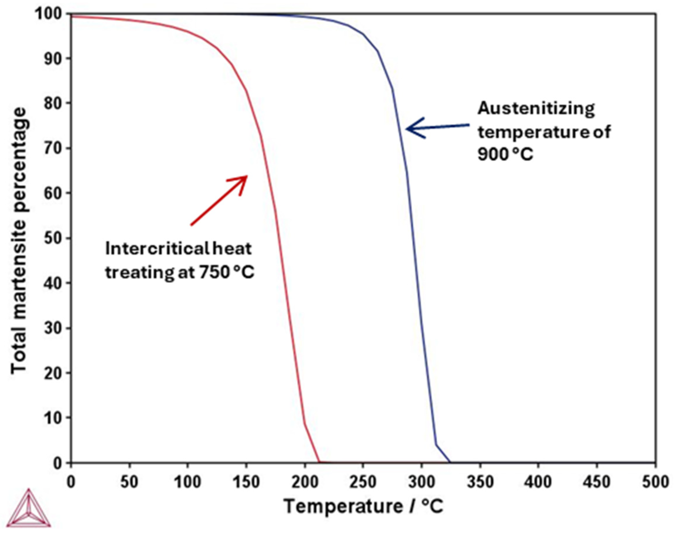
A comparison of the martensite percentage as a function of temperature is shown in Figure 4 for an austenitizing temperature of 900 °C and intercritical heat treating at 750 °C. Ms and Mf are lower for the intercritical treatment. Ms is 212 °C for the latter case and 320 °C for the former. This difference may result in a higher volume fraction of retained γ austenite for the intercritical treatment, which can improve the steel toughness after intercritical treatment, austempering, and quenching [1,2]. This effect is related to the suppression of the martensitic start temperature due to carbon enrichment and Mn partitioning into γ during intercritical holding, a mechanism that increases the thermal stability of austenite and delays its transformation to martensite [15,16]. Ms value agrees with that determined in other works, 350–374 °C in fully austenitized condition using experimental methods such as dilatometry [32,33], and similar trends have been reported in TRIP and medium-Mn steels subjected to intercritical treatments, confirming that partitioning kinetics are a key factor in defining Ms and in controlling the final balance between martensite and retained austenite [23,24].

3.2. Microstructural Characterization of Heat Treated Steel

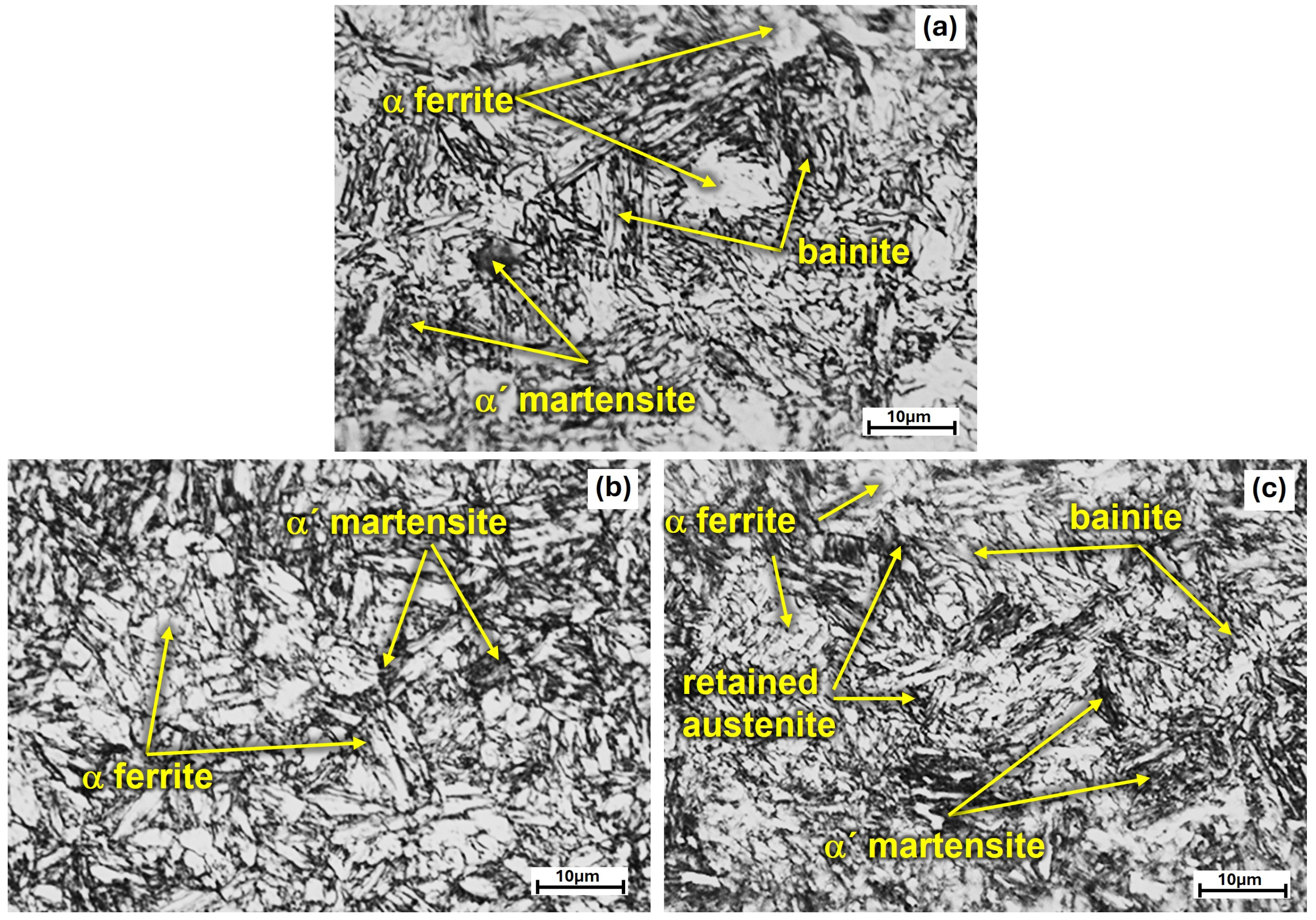
The OM microstructure for the air-cooled TRIP steel, quenched steel, and austempered-quenched steel, after intercritical heat treatment at 750 °C, is shown in Figure 5a–c, respectively. Air-cooled specimen shows a significant volume fraction of the α ferrite phase, recognized by its light contrast and polygonal morphology, and bainite microconstituent, a mixture of α ferrite and Fe3C phases, distinguished by its finer parallel laths of intermediate contrast [34], as indicated by the arrows in this figure. Nevertheless, a small quantity of martensite may be present as suggested by the observation of minor dark lath regions with irregular plates [33]. The TTT diagram corresponding to the intercritical treatment at 750 °C, Figure 3b, clearly shows that these microconstituents could be expected for an air-cooling rate of 10 °C/s. Additionally, no pearlite formation seems to be possible because this is slowed down and requires long times, exceeding 106 s, for its isothermal formation at approximately 550 °C. This fact is attributable to the Si content, which inhibits this transformation [33,35,36,37,38,39]. At the same time, carbon partitions preferentially into austenite during intercritical annealing, enriching it and lowering its transformation temperature. This enrichment further increases the stability of γ, so that part of it remains untransformed after cooling and contributes to the TRIP effect during deformation. Figure 3b also shows that the bainite formation is favored for the intercritical treatment, as indicated by the quickest start of this transformation at temperatures ranging from 250 to 400 °C. Quantitative metallography of this specimen indicates a 45 vol. % of α ferrite, close to the expected value of 50 vol. %. The bainite volume percentage was determined to be about 40%. These fractions are consistent with reports for similar medium-Mn or TRIP-aided steels subjected to air cooling from intercritical temperatures, where bainite forms as a secondary product due to Si suppressing pearlite [3,4,15,32,33]. In such steels, the limited martensite fraction can be attributed to the relatively low cooling rate, which allows partial bainitic transformation before reaching Ms, in agreement with the TTT diagram and previous experimental evidence [15,16]. The OM micrograph of the quenched specimen indicates in Figure 5b the presence of α ferrite and α’martensite, observed as dark irregular laths contrasting with the lighter ferrite grains, as expected for a fast-cooling rate of about 1000 °C/s. That is, the TTT diagram at 750 °C presents a high hardenability for this steel. This fact suggests that there is enough time at 200 °C to avoid the bainitic transformation, and thus to reach the Ms temperature, causing the remaining γ austenite to transform into α’martensite. The α ferrite volume percentage was determined to be about 47%, as expected for this intercritical treatment. The predominance of martensite in this specimen is a direct consequence of the high cooling rate, which suppresses any bainitic reaction and maximizes the transformation of austenite to martensite, in agreement with the hardenability trends derived from the Ps and Bs curve shifts in Figure 3b [33,40].
The OM micrograph of the austempered-quenched specimen, Figure 5c, reveals a complex mixture of phases. That is, the quenching from an intercritical temperature of 750 °C to 350 °C resulted in the formation of α ferrite and γ austenite. Then, because of austempering at 350 °C for 1800 s, some of the remaining γ austenite transformed into a bainite microconstituent, α ferrite + Fe3C phases. Finally, the subsequent quenching caused the martensitic transformation of some untransformed γ austenite. Nevertheless, a small volume fraction of retained γ austenite is formed due to the high Si content, which causes the partition of carbon from martensite to austenite, producing the stabilization of the γ retained austenite phase. This fact is consistent with the C-partitioning mechanism in TRIP-aided steels during austempering [5,12,16,40]. That is, the austempered-quenched specimen microstructure consists of a mixture of α ferrite, bainite, martensite, and retained γ austenite. The α ferrite, bainite and martensite microconstituents are indicated by arrows in Figure 5c; however, the identification of retained γ austenite is difficult in this micrograph due to the white contrast of the α ferrite and γ austenite phases [30]. Nevertheless, the martensite phase is in a dark contrast, the bainite is white parallel plates, the ferrite phase is light areas, and the retained phase corresponds to small light islands located between martensite or bainite plates, and distinctive sharp corners [34].
Figure 6a–c presents the SEI-SEM micrographs corresponding to those shown in Figure 5a–c, respectively.
These micrographs confirm the presence of parallel ferrite plates corresponding to the bainite phase, ferrite zones, and martensite formed in the air-cooled specimen from 750 °C, dual-phase field, Figure 6a. That is, this cooling rate is fast enough to promote the α’martensite formation. In this condition, the predominance of bainitic ferrite over martensite in the air-cooled specimen suggests that the austenite present during cooling underwent significant decomposition before reaching Ms, as predicted by the TTT diagram [28,29]. In contrast, the quenched specimen micrograph indicates the formation of non-parallel α’martensite plates and the ferrite phase, Figure 6b. This fact suggests that a fast-cooling rate of quenching treatment is sufficient to cause the martensite transformation from the two-phase zone, α + γ phases. Here, the absence of bainite is consistent with the calculated Bs for this composition, which is bypassed during rapid cooling, leading to a higher fraction of fresh martensite and, consequently, higher expected strength but lower ductility compared with the other two specimens, in agreement with hardenability–ductility trade-offs reported for TRIP-aided steels [5,12,16]
The SEM micrograph of the austempered-quenched specimen, Figure 6c, indicates more clearly the presence of the α ferrite, bainite, martensite and retained γ austenite microconstituents, as indicated by the arrows. The γ austenite presents a smaller size than that of α ferrite. The quantitative metallography results in approximately 45 vol. % α ferrite, 10 vol. % austenite, 25 vol. % bainite, and 20 vol. % α’ martensite, which seems to be reasonable according to the TTT diagram at 750 °C, Figure 3b. In this case, the ferrite phase corresponds to the gray regions, and the bainite microconstituent is parallel plates. In contrast, the martensite phase has a non-parallel plate morphology, and the retained austenite phase is small gray regions located among the martensite plates. Such a morphology and distribution are favorable for mechanical stability during deformation, as the surrounding hard martensite provides constraint, while the bainite–austenite interface can act as a site for strain–induced transformation, mechanisms that have been directly linked to enhanced strain hardening and delayed necking in TRIP steels [5,12,16].
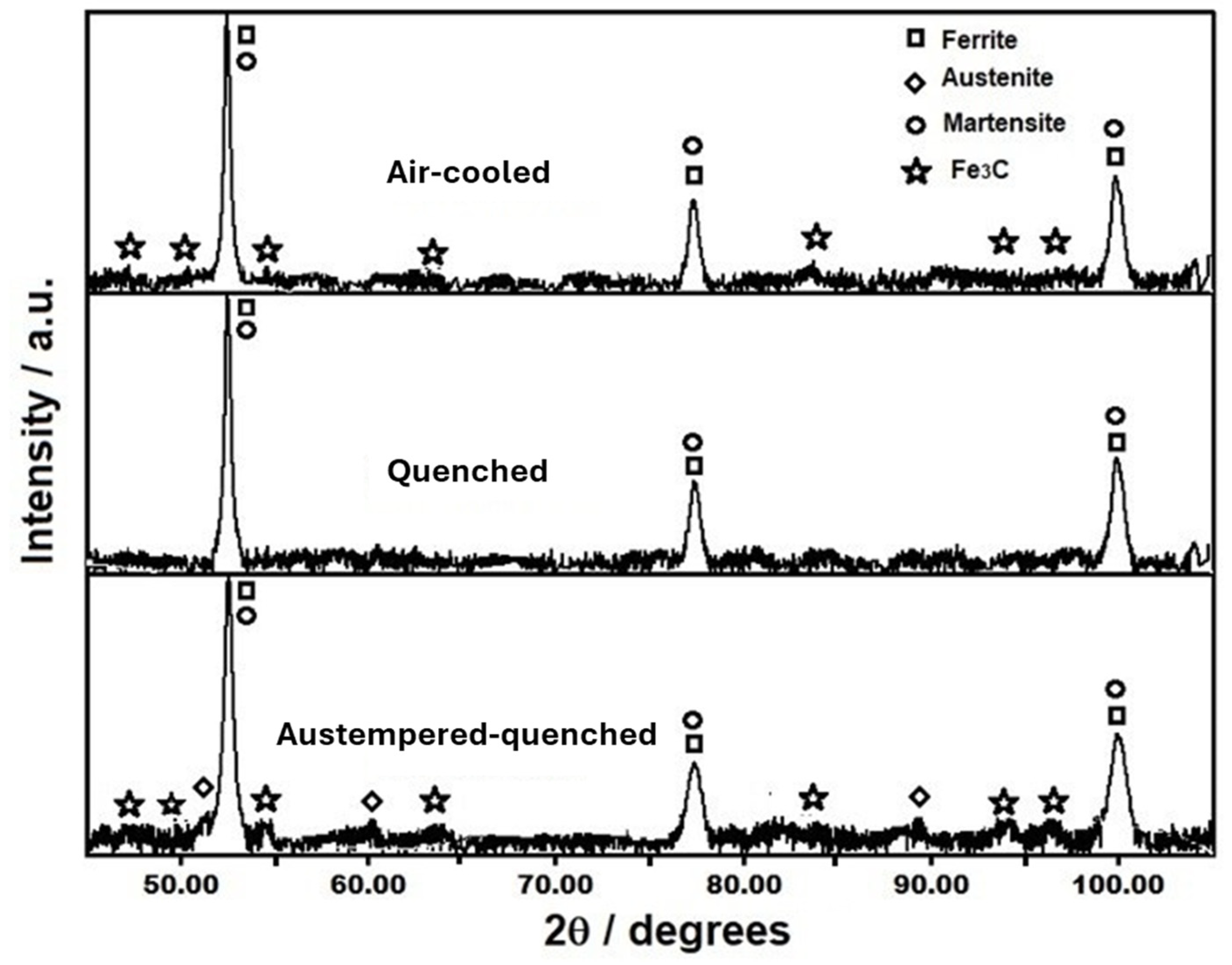
The XRD patterns, corresponding to Figure 6a–c, are shown in Figure 7. The identified phases are α ferrite, α’martensite and Fe3C phases for the air-cooled condition, as expected from Thermo-Calc results, Figure 3b, and as observed in OM and SEM micrographs, Figure 5a and Figure 6a. The XRD peaks of α’ martensite overlapped with those corresponding to the α ferrite phase. Thus, the determination of the former phase is not possible. The quenched specimen pattern exhibits only XRD peaks corresponding to the α phase, as the XRD peaks for the α’ phase are overlapped with those of the former, see Figure 7. No γ austenite phase seems to be present in this pattern. In the case of the austempered-quenched specimen, the α ferrite, Fe3C, γ austenite and α’ martensite phases are present in its corresponding XRD pattern. These identified phases agree with those predicted by Thermo-Calc results and the SEM observed microstructure, Figure 6c. The XRD analysis shows that the volume percentage of retained γ austenite is about 5%. About 5–10 vol. % retained γ austenite has been reported for this type of steel in the literature [1,2]. This percentage is sufficient to obtain toughness and ductility in these steels [1,2]. Furthermore, several works [10,31,37] have pointed out that the higher the intercritical treatment temperature, the lower the volume fraction of retained γ austenite in the austempered steel. This is attributed to the lower carbon content and stability of the austenite formed at higher intercritical temperatures.
In the present case, the 750 °C intercritical temperature results in a γ austenite fraction with sufficient carbon enrichment to allow partial retention in the austempered-quenched specimen but not in the other two. The absence of detectable γ austenite in the air-cooled and quenched specimens by XRD indicates complete transformation during cooling, consistent with the more rapid transformation paths predicted by the TTT diagram for their respective cooling conditions [40,41]. These findings experimentally confirm the phase stability trends inferred from the TTT and Ms data in Section 3.1, showing good consistency between Thermo-Calc predictions (ferrite–austenite coexistence at 750 °C and subsequent bainite/martensite formation upon cooling) and the phases identified by OM, SEM, and XRD.

3.3. Mechanical Characterization of Heat-Treated Steel

The Vickers hardness results of the three specimens are shown in Table 2. The highest value corresponds to the quenched specimen in the quenched condition. In contrast, the air-cooled condition presents the lowest hardness. This fact is consistent with the phase fractions reported in Section 3.2.
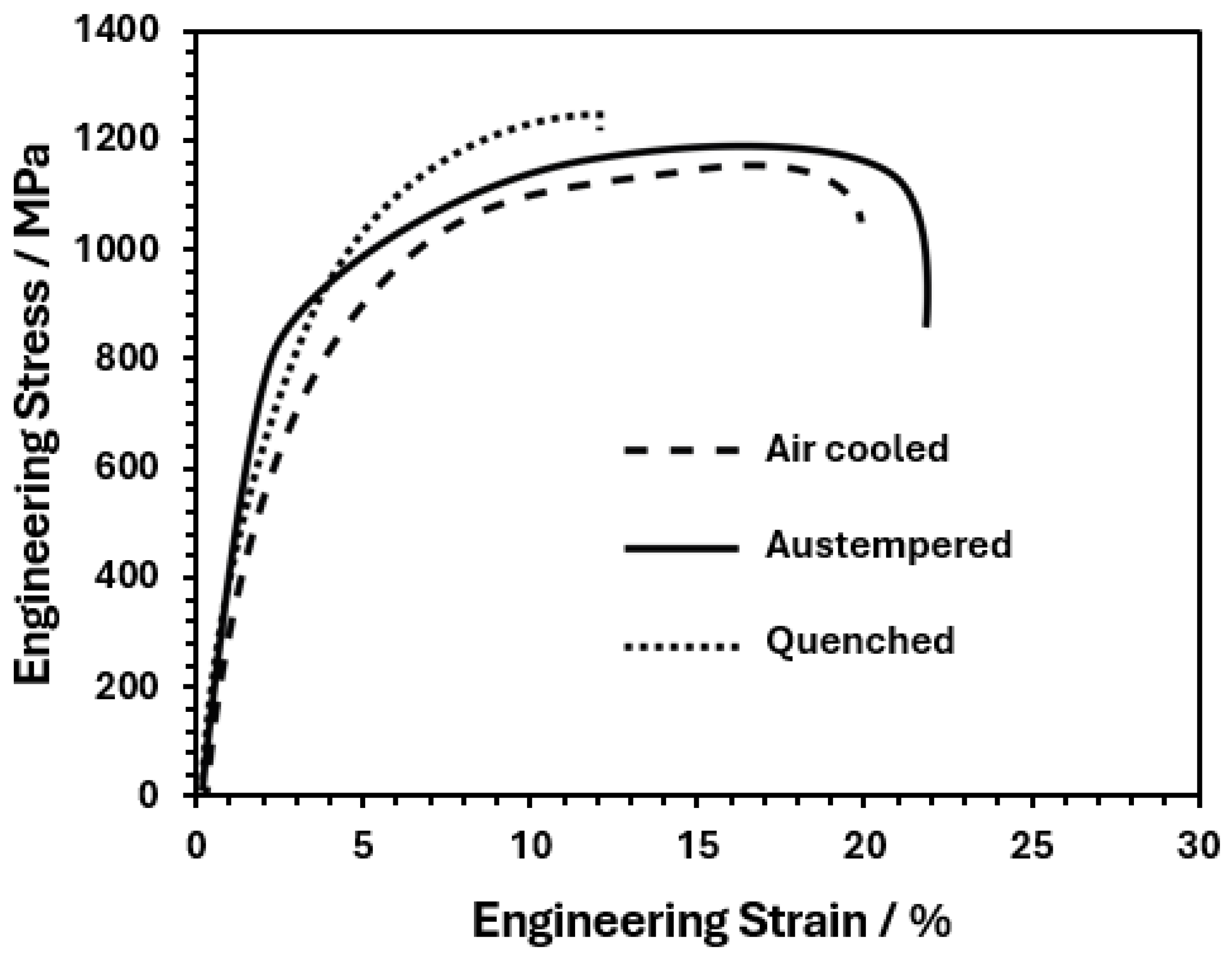
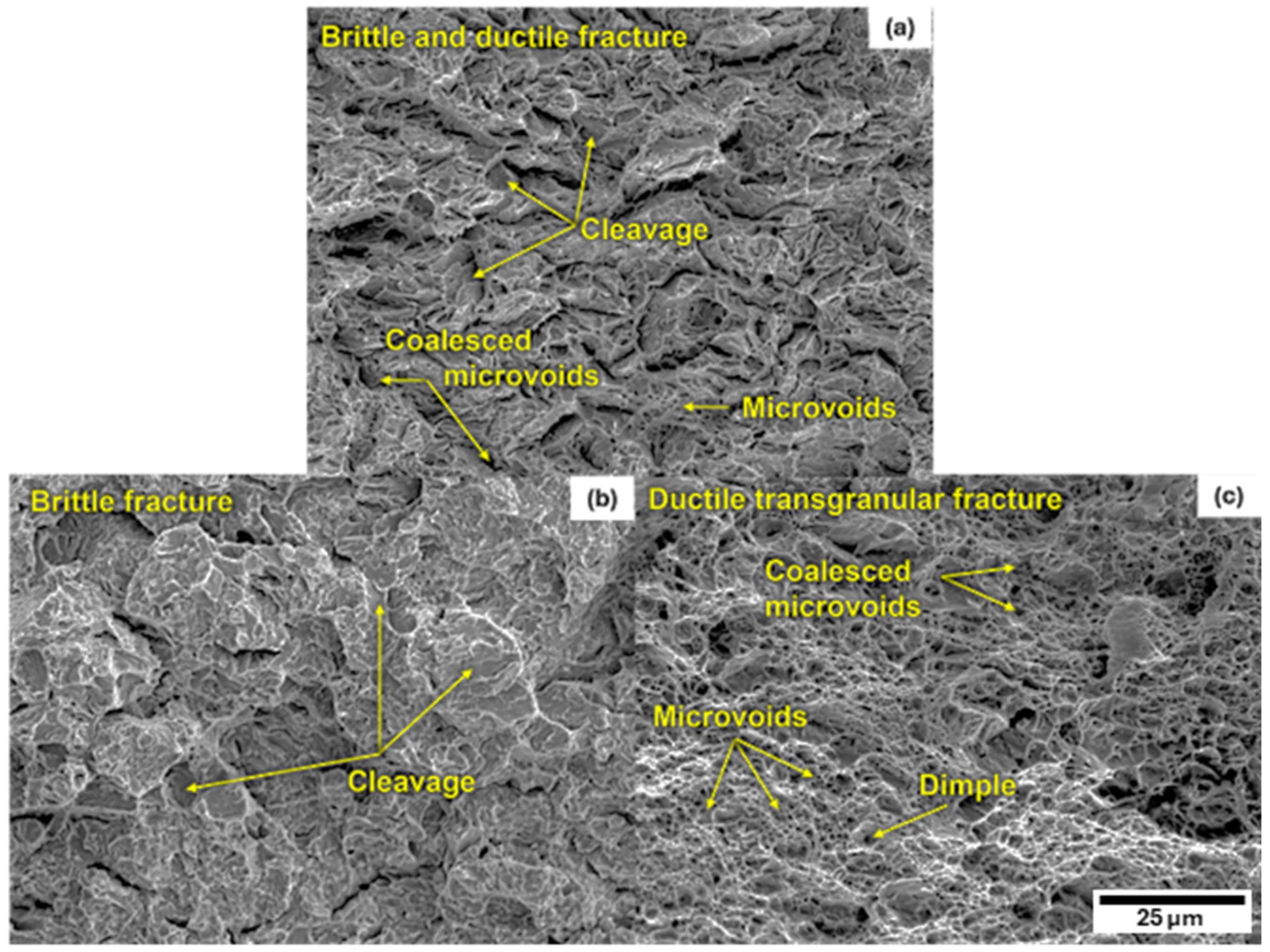
Figure 8 shows the engineering stress versus engineering strain tension test curve, and Table 2 summarizes the tensile test properties. The highest ultimate tensile strength, UTS, also corresponds to the quenched specimen, while the lowest one corresponds to the air-cooled specimen. Likewise, the austempered-quenched specimen presented the longest elongation, while the one quenched had the shortest one. That is, the toughness of the austempered-quenched specimen is higher than that of the other two. This fact is clearly shown in Figure 9c, the SEM fractography corresponding to the austempered-quenched specimen, which illustrates a ductile transgranular fracture mode. In contrast, the quenched specimen presents a brittle fracture mode by cleavage, predominantly transgranular, but with localized regions showing the alignment of cleavage facets along prior austenite grain boundaries (Figure 9a). The air-cooled specimen presents a mixture of brittle and ductile fractures.
This mechanical behavior can be explained using the formed phases and microconstituents for each heat treatment as follows: The highest UTS and VHN for the quenched specimen is due to the formation of a predominantly martensitic microstructure with ferrite during quenching of austenite with 0.33 wt. % C, Figure 2. In addition, the γ austenite phase also contains 1.47 wt. % Si and 1.5 wt. % Mn, which causes a notable increase in hardenability, Figure 3b, and permits the obtaining of a significant volume fraction of martensite. Furthermore, the air-cooled TRIP steel also presented the presence of martensite and bainite in addition to the α ferrite phase. In the air-cooled and quenched specimens, the absence of retained γ austenite, detected by XRD, indicates that no strain-induced transformation occurred during deformation. Thus, the load-bearing capacity is controlled by the ferrite–martensite or ferrite–bainite mixtures without the additional work hardening provided by the TRIP effect [5,12,16].
On the other hand, the air-cooled and quenched specimens presented continuous yielding with the lowest YS, while the austempered-quenched specimen had discontinuous yielding with the highest YS. The discontinuous yielding in steels, in general, arises from the interaction between dislocations and interstitial atoms [38]. In the case of the air-cooled and quenched specimens, most of the C atoms are in the martensite phase, leaving few atoms for dislocation interaction, which also causes a low YS. In contrast, the austempered-quenched one exhibits C atom migration from the martensite phase, primarily due to its high Si content, which retards carbide precipitation and promotes a higher amount of C in solid solution, and to the γ austenite and α ferrite phases, facilitating its interaction with dislocations and thereby promoting discontinuous yielding. These mechanical responses are consistent with Mn-assisted austenite stabilization and carbon partitioning during intercritical holding [2,5,9,15]. This fact can also be adopted as the reason for the highest YS.
The highest elongation of the austempered-quenched specimen is attributable to the presence of the stabilized g austenite phase and the TRIP effect, which delays necking by progressive strain-induced transformation into martensite [2]. In addition, the bainitic microstructure generated during the austempering step provides crack-blunting interfaces and enhances strain partitioning, which together with the TRIP effect explains the superior toughness of this condition compared to the quenched specimen. These features are consistent with an enhanced strain-hardening capacity, even though a full quantification of the work-hardening index was not performed.
Quantitative assessment of the fracture surfaces, considering all visible cavities (including incipient voids, partially coalesced regions, and fully developed dimples), showed that the cavitated area fraction was significantly higher in the austempered-quenched specimen (≈16.7%) than in the quenched one (≈3.8%), while the air-cooled condition exhibited an intermediate value (≈7.3%). This cavitated fraction reflects the overall extent of microvoid coalescence and therefore provides a direct measure of the ductile contribution to fracture. The high value of the austempered-quenched specimen is consistent with its superior elongation and TRIP effect, whereas the low value of the quenched specimen corresponds to cleavage-dominated fracture. The intermediate response of the air-cooled condition reflects its mixed brittle–ductile character.
Conversely, the lowest elongation and toughness of the air-cooled and quenched specimens are due to the presence of martensite, which increases strength but reduces ductility by promoting brittle fracture features as seen in their SEM fractographs, reflecting differences in local stress distribution and strain partitioning between ferrite, martensite, bainite, and retained austenite. In the austempered-quenched specimen, the presence of retained austenite favors gradual deformation transfer between phases, while in the others the absence of retained austenite prevents this effect.

3.4. Relation of Microstructure to Mechanical Properties

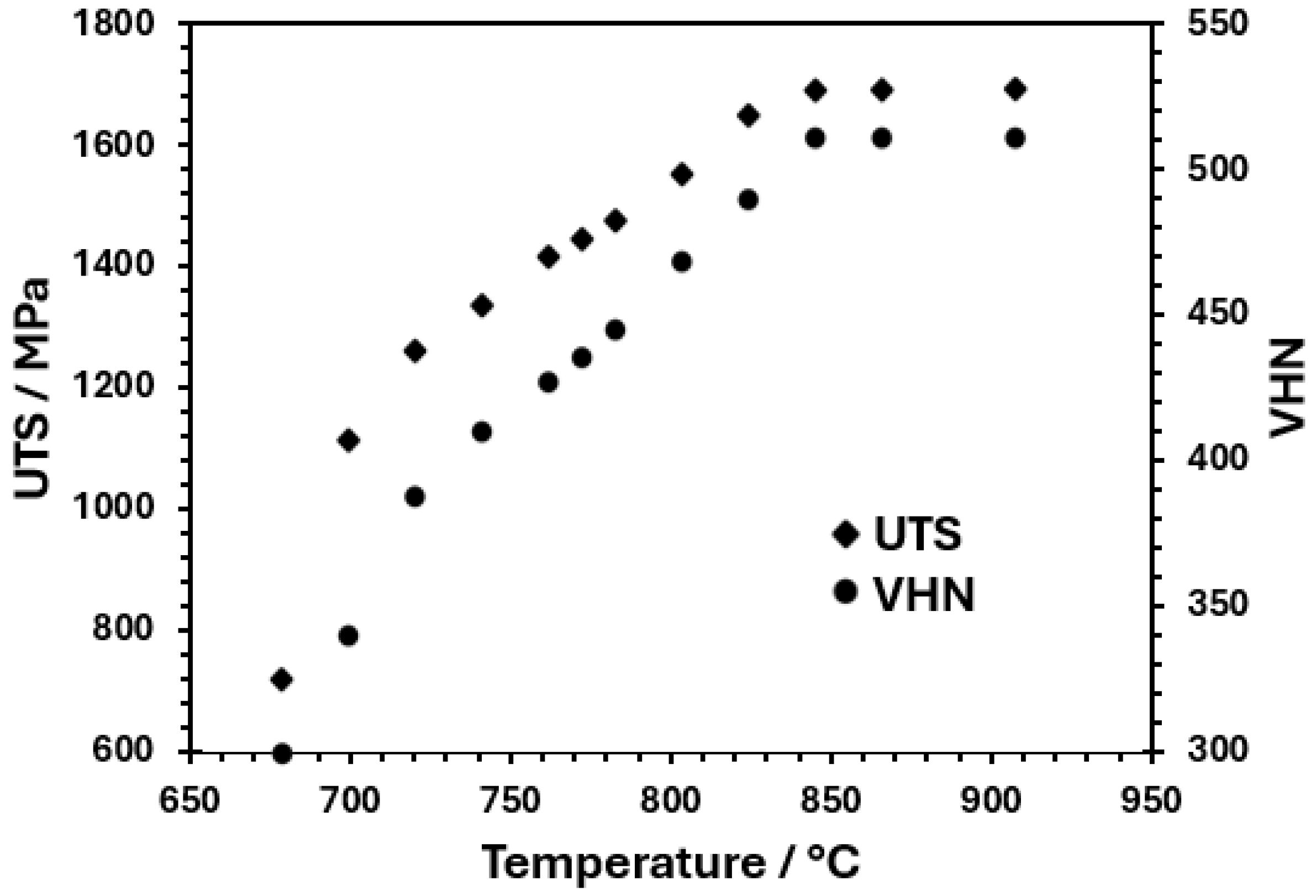
Figure 10 shows the Thermo-Calc-calculated plot of VHN and UTS as a function of the intercritical treatment temperature. The present work VHN and UTS values for the quenched condition, as shown in Table 2, agree well with the calculated ones. This plot indicates that it is possible to obtain a wide range of mechanical properties for this steel using the intercritical heat treatment and subsequent quenching.
This plot indicates that it is possible to obtain a wide range of mechanical properties for this steel using the intercritical heat treatment and subsequent quenching. This steel characteristic is based on the martensite formation during the steel quenching from the two-phase region, γ + α. The formed martensite can achieve up to 0.5 wt. % C at temperatures close to A3, which permits the obtaining of hardness of 480 VHN and UTS close to 1600 MPa. The martensite formation is favored by the high hardenability of this TRIP steel at temperatures of the two-phase region, α + γ phases. Nevertheless, the ductility is diminished considerably. The most suitable mechanical properties for this steel are those of the austempered and quenched steel after intercritical heat treatment. This treatment produced the formation of hardened martensite, tough and hardened bainite, and ductile and tough stabilized retained γ austenite. These microconstituents provide a YS, UTS and elongation percent of about 800 MPa, 1200 MPa, and 20%, respectively. The stabilized retained γ austenite is responsible for the high ductility and toughness of this TRIP steel. The stabilization of the retained γ austenite is caused by the addition of γ austenite-forming elements, such as Mn and Si. Both alloying elements decrease Ms and Mf, facilitating the formation of the retained γ austenite phase. Moreover, the Si content also contributes to the stabilization of the retained γ austenite phase due to the migration of C atoms from the high-carbon martensite towards the γ austenite [2].

4. Conclusions

A study of the microstructure evolution of a TRIP Fe –1.4Si –2.6Mn –0.17C steel was conducted for different heat treatments, and the conclusions are summarized as follows:
  • TC-calculated microstructure evolution and mechanical properties for the heat- treated steel specimens agree well with the experimental ones. Additionally, Thermo-Calc permits the determination of TTT diagrams at intercritical temperatures, which can be used to design heat treatments and to predict the phases and microconstituents after heat treatment.
  • The quenching treatment of this TRIP steel, from intercritical temperatures, is a viable alternative for producing hardened martensite with VHN value up to 430 and UTS of 1255 MPa. However, ductility decreases as the intercritical treatment temperature increases due to the presence of a higher volume fraction of martensite.
  • The austempered-quenched steel, after intercritical treatment, presented a tensile strength similar to that of the quenched steel but with more ductility, which is attributable to the stabilization of retained γ austenite associated with the high Si and Mn content.
  • The air-cooling treatment of this TRIP steel is also a good possibility, since it provides a high VHN value of 406 and UTS of 1190 MPa, along with good ductility, due to the bainite formation and a small fraction of martensite during air cooling, which is attributed to its high hardenability, as shown in the TC-calculated TTT diagram at 750 °C.

Author Contributions

Conceptualization, V.M.-L., H.J.D.-R. and M.L.S.-M.; methodology, V.M.-L. and V.M.L.-H.; software, V.M.-L., M.A.B.-Z. and M.L.S.-M.; validation, V.M.-L. and V.M.L.-H.; formal analysis, M.L.S.-M. and V.M.-L.; investigation, M.A.B.-Z. and M.L.S.-M.; resources, M.L.S.-M. and V.M.L.-H.; data curation, V.M.-L. and M.A.B.-Z.; writing—original draft preparation, V.M.-L., V.M.L.-H. and M.L.S.-M.; writing—review and editing, V.M.-L., M.L.S.-M. and M.A.B.-Z.; visualization, M.L.S.-M.; supervision H.J.D.-R. and V.M.L.-H.; project administration, M.L.S.-M. and V.M.L.-H.; funding acquisition, M.L.S.-M. and V.M.L.-H. All authors have read and agreed to the published version of the manuscript.

Funding

This research received no external funding.

Data Availability Statement

The data that supports the findings of this study are available from the corresponding author upon request.

Acknowledgments

The authors acknowledge financial support from IPN-SIP 2025-Beifi.

Conflicts of Interest

The authors declare no conflicts of interest.

References

  1. Rana, R.; Singh, S.B. (Eds.) Automotive Steels: Design, Metallurgy, Processing and Applications; Woodhead Publishing Series in Metals and Surface Engineering; Elsevier: Amsterdam, The Netherlands, 2016; pp. 217–249. [Google Scholar]
  2. Fonstein, N. Advanced High Strength Sheet Steels: Physical Metallurgy, Design, Processing, and Properties; Springer International Publishing: Cham, Switzerland, 2015; pp. 17–60. [Google Scholar]
  3. Avila, D.; van Bohemen, S.M.C.; Huizenga, R.M.; Offerman, S.E.; Santofimia, M.J. Shortening the heat treatment of third-generation AHSS by forming carbide-free bainite in the presence of martensite. Mater. Sci. Eng. A 2025, 931, 148241. [Google Scholar] [CrossRef]
  4. Morales-Rivas, L. Viewpoints on technological aspects of advanced high-strength bainitic steels. Metals 2022, 12, 195. [Google Scholar] [CrossRef]
  5. Bai, X.; Yu, Y.; Hu, B.; Wang, H.; Wang, W.; Liu, S.; Liu, W. Insights into the role of retained austenite stability in TRIP-aided steel: Ductilizing and toughening. J. Mater. Res. Technol. 2024, 33, 7698–7708. [Google Scholar] [CrossRef]
  6. Yang, G.; Zhuang, C.; Li, C.; Lan, F.; Yao, H. Study on high-temperature mechanical properties of Fe–Mn–C–Al TWIP/TRIP steel. Metals 2021, 11, 821. [Google Scholar] [CrossRef]
  7. Jia, G.; Li, Y.; Ding, W. Alloy composition and process design based on thermodynamic and kinetic simulation: The case of medium Mn steel. Calphad 2023, 82, 102601. [Google Scholar] [CrossRef]
  8. Mehrabi, A.; Zurob, H.S.; McDermid, J.R. Process maps for predicting austenite fraction (vol %) in medium-Mn third-generation AHSS. Materials 2024, 17, 993. [Google Scholar] [CrossRef]
  9. Lu, J.; Wang, S.; Yu, H.; Wu, G.; Gao, J.; Wu, H.; Zhao, H.; Zhang, C.; Mao, X. Structure-property relationship in vanadium micro-alloyed TRIP steel subjected to the isothermal bainite transformation process. Mater. Sci. Eng. A 2023, 878, 145208. [Google Scholar] [CrossRef]
  10. Kim, S.J.; Lee, C.G.; Choi, I.; Lee, S. Effects of heat treatment and alloying elements on the microstructures and mechanical properties of 0.15 wt % C TRIP-aided cold-rolled steel sheets. Metall. Mater. Trans. A 2001, 32A, 505–514. [Google Scholar] [CrossRef]
  11. Pantilimon, M.C.; Berbecaru, A.C.; Gherghescu, I.A.; Coman, G.; Ciucă, S.; Grecu, A.; Sohaciu, M.G.; Dumitrescu, R.E.; Predescu, C. Comparative evaluation of the TRIP effect in steels with different contents of Mn and Al. Metals 2022, 12, 443. [Google Scholar] [CrossRef]
  12. Morawiec, A.; Skowronek, A.; Kozłowska, A.; Garcia-Mateo, C.; Grajcar, A. Effect of prior martensite formation on the bainite transformation in kinetics in high-strength 3% Mn multiphase steel. J. Therm. Anal. Calorim. 2023, 148, 1365–1371. [Google Scholar] [CrossRef]
  13. Soleimani, M.; Kalhor, A.; Mirzadeh, H. Transformation-induced plasticity (TRIP) in advanced steels: A review. Mater. Sci. Eng. A 2020, 795, 140023. [Google Scholar] [CrossRef]
  14. Thermo-Calc Software. Solutions for ICME. Available online: https://thermocalc.com/solutions/solutions-for-icme/ (accessed on 1 July 2025).
  15. Kumpati, J.; Hasan, S.M.; Bonvalet Rolland, M.; Borgenstam, A. Retained austenite stability: A Comparative Study of Two-Phase and Bulk Microstructures. Metall. Mater. Trans. A 2024, 55, 466–476. [Google Scholar] [CrossRef]
  16. Mehrabi, A.; Zurob, H.S.; Benrabah, I.-E.; McDermid, J.R. Austenite formation in a medium-Mn steel during intercritical annealing via in situ high-energy X-ray diffraction. J. Mater. Res. Technol. 2024, 30, 2158–2167. [Google Scholar] [CrossRef]
  17. Lamari, M.; Allain, S.Y.P.; Geandier, G.; Ponçot, M.; Perlade, A.; Zhu, K.O. Behaviour of TRIP-aided medium Mn steels investigated by in situ synchrotron X-ray diffraction experiments and microstructure-based micromechanical modelling. Int. J. Plast. 2024, 173, 103866. [Google Scholar] [CrossRef]
  18. Kozłowska, A. Dilatometric study on phase transformations in non-deformed and plastically deformed medium-Mn multiphase steels with increased Al and Si additions. Materials 2024, 17, 1051–1058. [Google Scholar] [CrossRef]
  19. Thermo-Calc Software. Steel Model Library. Available online: https://thermocalc.com/products/add-on-modules/steel-model-library/ (accessed on 2 July 2025).
  20. Yan, J.; Ågren, J.; Jeppsson, J. Pearlite in multicomponent steels: Phenomenological steady-state modeling. Metall. Mater. Trans. A 2020, 51, 1978–2001. [Google Scholar] [CrossRef]
  21. Leach, L.; Kolmskog, P.; Höglund, L.; Hillert, M.; Borgenstam, A. Critical driving forces for formation of bainite. Metall. Mater. Trans. A 2018, 49, 4509–4520. [Google Scholar] [CrossRef]
  22. Leach, L.; Ågren, J.; Höglund, L.; Borgenstam, A. Diffusion-controlled lengthening rates of bainitic ferrite a part of the Steel Genome. Metall. Mater. Trans. A 2019, 50, 2613–2618. [Google Scholar] [CrossRef]
  23. Huyan, F.; Hedström, P.; Höglund, L.; Borgenstam, A. A thermodynamic-based model to predict the fraction of martensite in steels. Metall. Mater. Trans. A 2016, 47, 4404–4410. [Google Scholar] [CrossRef]
  24. Stormvinter, A.; Borgenstam, A.; Ågren, J. Thermodynamically based prediction of the martensite start temperature for commercial steels. Metall. Mater. Trans. A 2012, 43, 3870–3879. [Google Scholar] [CrossRef]
  25. Park, S.J.; Heogh, W.; Yang, J.; Kang, S.; Jeong, W.; Lee, H.; Jang, T.S.; Jung, H.D.; Jahazi, M.; Han, S.C.; et al. Meta-structure of amorphous-inspired 65.1Co28.2Cr5.3Mo lattices augmented by artificial intelligence. Adv. Compos. Hybrid Mater. 2024, 7, 224. [Google Scholar] [CrossRef]
  26. Thermo-Calc Software. Steel and Fe-Alloys Databases, TCFE Databases; Thermo-Calc Software: Solna, Sweden, 2021; Available online: https://thermocalc.com/products/databases/steel-and-fe-alloys/ (accessed on 1 July 2025).
  27. ASTM E8/E8M-22; Standard Test Methods for Tension Testing of Metallic Materials. ASTM International: West Conshohocken, PA, USA, 2022.
  28. ASTM E384-22; Standard Test Method for Microindentation Hardness of Materials. ASTM International: West Conshohocken, PA, USA, 2022.
  29. Callister, W.D., Jr.; Rethwisch, D.G. Materials Science and Engineering: An Introduction, 10th ed.; Wiley: Hoboken, NJ, USA, 2022; Chapter 9; p. 337. [Google Scholar]
  30. Bhadeshia, H.K.D.H.; Honeycombe, R.W.K. Steels: Microstructure and Properties, 4th ed.; Butterworth-Heinemann: Oxford, UK, 2017; p. 61. [Google Scholar]
  31. Erişir, E.; Bilir, O.G. Effect of intercritical annealing temperature on phase transformations in medium carbon dual phase steels. J. Mater. Eng. Perform. 2014, 23, 1055–1061. [Google Scholar] [CrossRef]
  32. Hofer, C.; Leitner, H.; Winkelhofer, F.; Clemens, H.; Primig, S. Structural characterization of ‘carbide-free’ bainite in a Fe–0.2C–1.5Si–2.5Mn steel. Mater. Charact. 2015, 102, 85–91. [Google Scholar] [CrossRef]
  33. Gulbay, O.; Gramlich, A.; Krupp, U. Effects of silicon and aluminum alloying on phase transformation and microstructure evolution in Fe–0.2C–2.5Mn steel: Insights from continuous-cooling-transformation and time-temperature-transformation diagrams. Steel Res. Int. 2024, 95, 2400159. [Google Scholar] [CrossRef]
  34. Vander Voort, G.F. (Ed.) Metallography and Microstructures. In ASM Handbook; ASM International: Materials Park, OH, USA, 2004; Volume 9, pp. 103–462. [Google Scholar]
  35. Li, F.; Shang, X.; Zhao, J.; Wang, X.; Xu, X.; Wu, Z. Effects of annealing temperature on microstructure and mechanical properties of a low density δ-TRIP steel plate via intercritical quenching-annealing process. Mater. Sci. Eng. A 2024, 900, 146503. [Google Scholar] [CrossRef]
  36. Zhang, S.; Zhou, W.; Hu, F.; Wu, K.; Yershov, S. Influence of intercritical annealing temperature on TRIP/TWIP effect of retained austenite and tensile deformation mechanism of IQ&P steel. J. Mater. Res. Technol. 2024, 33, 3619–3634. [Google Scholar]
  37. Bhadhon, K.M.H.; Wang, X.; McNally, E.A.; McDermid, J.R. Effect of intercritical annealing parameters and starting microstructure on the microstructural evolution and mechanical properties of a medium-Mn third generation advanced high strength steel. Metals 2022, 12, 356. [Google Scholar] [CrossRef]
  38. Rana, R.; Cordova-Tapia, E.; Morales-Rivas, L.; Jimenez, J.A.; Garcia-Mateo, C. Mechanical behaviour and microstructural characteristics of high-silicon ultra-strong bainitic steels for hot rolling practice. Mater. Sci. Eng. A 2025, 931, 148236. [Google Scholar] [CrossRef]
  39. Hu, Z.; Fu, H. Effect of Si Content on Microstructure and Properties of Low-Carbon Medium-Manganese Steel after Intercritical Heat Treatment. Metals 2024, 14, 675. [Google Scholar] [CrossRef]
  40. Xiao, H.; Zhao, G.; Xu, D.; Cheng, Y.; Bao, S. Effect of Microstructure Morphology of Q&P Steel on Carbon and Manganese Partitioning and Stability of Retained Austenite. Metals 2022, 12, 1613. [Google Scholar] [CrossRef]
  41. Long, X.; Liu, W.; Zhu, R.; Zhang, Y.; Zhang, F.; Yang, Z.; Li, Y. Effect of the Cooling Rate in the Medium Temperature Zone on the Phase Transformation and Microstructure of Carbide-Free Bainitic Steel. J. Mater. Res. Technol. 2024, 29, 59. [Google Scholar] [CrossRef]
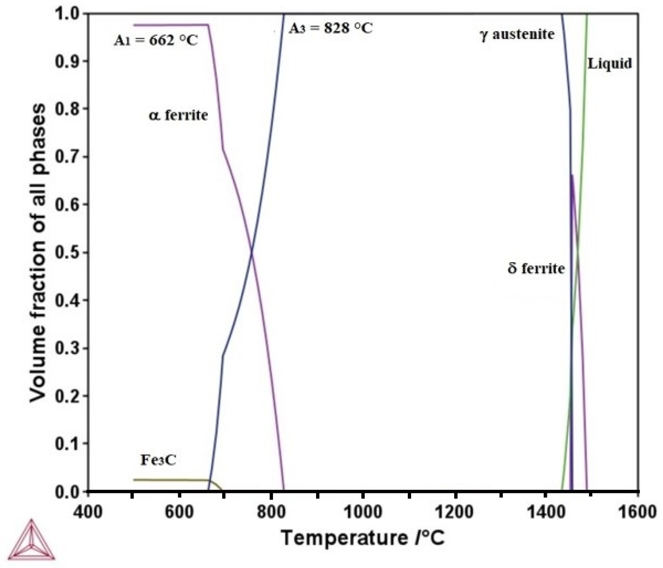
Figure 1. Thermo-Calc calculated plot of the amount of equilibrium phase fraction versus temperature for the TRIP steel.
Metals 15 01096 g001
Figure 2. Thermo-Calc calculated plot of carbon content in the γ austenite phase as a function of temperature for the TRIP steel.
Metals 15 01096 g002
Figure 3. Thermo-Calc calculated TTT diagram for the TRIP steel at (a) 900 °C and (b) intercritical treatment at 750 °C.
Metals 15 01096 g003
Figure 4. Thermo-Calc calculated plot of total martensite percentage as a function of temperature for the TRIP steel at 900 °C and intercritical treatment at 750 °C.
Metals 15 01096 g004
Figure 5. OM micrographs of the TRIP steel: for the (a) air-cooled, (b) quenched, and (c) austempered-quenched specimens.
Metals 15 01096 g005
Figure 6. SEM micrographs for the TRIP steel (a) air-cooled, (b) quenched, and (c) austempered-quenched specimens.
Metals 15 01096 g006
Figure 7. XRD patterns of the TRIP steel: air-cooled, quenched, and austempered-quenched specimens.
Metals 15 01096 g007
Figure 8. Engineering stress–strain curves of the heat-treated TRIP steel specimens.
Metals 15 01096 g008
Figure 9. SEM fractographs of the TRIP steel tension specimens: (a) air-cooled, (b) quenched, and (c) austempered-quenched.
Metals 15 01096 g009
Figure 10. Thermo-Calc-calculated plot of UTS and VHN versus intercritical treatment temperature for the TRIP steel.
Metals 15 01096 g010
Table 1. Chemical composition of TRIP steel.
ElementCMnSiAlTi
wt. %0.172.601.400.0230.024
ElementVCuNbPS
wt. %0.010.0120.010.0070.001
Table 2. Vickers hardness and tensile properties of heat-treated TRIP steel specimens.
SpecimenVHNYS (MPa)UTS (MPa)Elongation %
Air-cooled406690119015
Quenched43066512559
Austempered-quenched420820120018
Disclaimer/Publisher’s Note: The statements, opinions and data contained in all publications are solely those of the individual author(s) and contributor(s) and not of MDPI and/or the editor(s). MDPI and/or the editor(s) disclaim responsibility for any injury to people or property resulting from any ideas, methods, instructions or products referred to in the content.