Article

The Impact of Hydrogen Charging Time on Microstructural Alterations in Pipeline Low-Carbon Ferrite–Pearlite Steel

1
Institute of Metal Science, Equipment, and Technologies with Center of Hydro- and Aerodynamics “Acad. A. Balevski”, Bulgarian Academy of Sciences, 67 “Shipchenski Prohod” Str., 1574 Sofia, Bulgaria
2
National Center for Mechatronics and Clean Technologies, 8 Kliment Ohridski Blvd., Building 8, 1756 Sofia, Bulgaria
3
Institute of Mechanics, Bulgarian Academy of Sciences, Acad. Georgi Bonchev Str., Bl. 4, 1113 Sofia, Bulgaria
*
Author to whom correspondence should be addressed.
Metals 2025, 15(10), 1079; https://doi.org/10.3390/met15101079 (registering DOI)
Submission received: 20 August 2025 / Revised: 16 September 2025 / Accepted: 23 September 2025 / Published: 27 September 2025
(This article belongs to the Special Issue Hydrogen Embrittlement of Metals: Behaviors and Mechanisms)

Abstract

This study investigates the effect of hydrogen charging time on the mechanical properties and microstructural evolution of low-carbon ferrite–pearlite steel that has been in service for over 30 years in natural gas transmission. Specimens were subjected to in-situ electrochemical hydrogen charging for varying durations, followed by tensile testing. Detailed microstructural analysis was performed using scanning electron microscopy (SEM), and transmission electron microscopy (TEM). Despite negligible changes in the overall hydrogen content ( C H ≈ 4.0 wppm), significant alterations in fracture morphology were observed. Fractographic and TEM analyses revealed a clear transition from ductile fracture in uncharged specimens to a predominance of brittle fracture modes (quasi-cleavage, intergranular, and transgranular) in hydrogen-charged samples. The results show time-dependent microstructural changes, including increased dislocation density and the formation of prismatic loop debris, particularly within the ferrite phase. Prolonged charging leads to localized embrittlement, which is explained by enhanced hydrogen trapping at ferrite-cementite boundaries, grain boundaries, and dislocation cores. TEM investigations further indicated a sequential activation of hydrogen embrittlement mechanisms: initially, Hydrogen-Enhanced Localized Plasticity (HELP) dominates within ferrite grains, followed by Hydrogen-Enhanced Decohesion (HEDE), particularly at ferrite-cementite interfaces in pearlite colonies. These findings demonstrate that extended hydrogen charging promotes defect localization, dislocation pinning, and interface decohesion, ultimately accelerating fracture propagation. The study provides valuable insight into the degradation mechanisms of ferrite-pearlite steels exposed to hydrogen, highlighting the importance of charging time. The results are essential for assessing the reliability of legacy pipeline steels and guiding their safe use in future hydrogen transport infrastructure.

1. Introduction

Low-carbon pipeline steels are widely used in the energy and petrochemical industries due to their favorable mechanical properties, weldability, and cost-effectiveness. However, their long-term reliability is significantly limited by their susceptibility to hydrogen-induced cracking [1], hydrogen embrittlement [2], and high-temperature hydrogen attack [3]. Once hydrogen permeates the material, the macromechanical properties deteriorate [4], including tensile strength, yield strength, hardness, impact toughness, elongation at fracture, wear resistance and crack propagation rate [5,6,7].
The factors influencing the susceptibility of low-carbon steels to hydrogen embrittlement are primarily related to their specific structural characteristics, such as a banded microstructure consisting of alternating layers of ferrite and pearlite [8,9]; grain size, which determines the total length of the boundaries and the number and distance of cementite lamellae, and various types of inclusions, particularly MnS [9,10,11].
Hydrogen damage manifests in several forms:
  • Hydrogen-Induced Crackingor Hydrogen Environment-Assisted Cracking occurs due to the recombination of atomic hydrogen into a molecule inside the material [12];
  • Hydrogen blistering arises when hydrogen enters the metal from hydrogen-containing environments and accumulates around inclusions or other defects. With increasing hydrogen pressure, the integrity of the metal is eventually compromised. The susceptibility to this type of damage depends on the structure of the metallic material. Ferritic, martensitic, and duplex steels are generally less resistant to this form of damage compared to austenitic steels [13];
  • Stress-Oriented Hydrogen-Induced Cracking [12] leads to premature failure of ductile steels and alloys under sustained loading at stress levels below the yield strength. The resulting cracks are oriented perpendicular to the direction of hydrogen diffusion;
  • Sulfide Stress Cracking [12] manifests as longitudinal cracking due to stress from externally applied loads. This phenomenon is particularly critical in industries that process crude oil and natural gas containing hydrogen sulfide. Austenitic and duplex steels (austenitic–ferritic) are particularly susceptible to this form of corrosion, especially at elevated temperatures [13]. This type of degradation also affects steels under load, resulting in crack propagation parallel to the direction of hydrogen diffusion;
  • Internal Hydrogen-Assisted Cracking [14] refers to internal cracking caused by hydrogen that accumulates during manufacturing or assembly processes.
According to the HELP mechanism, hydrogen facilitates dislocation movement by lowering the resistance to slip, thereby promoting localized plasticity and reducing material strength [2,5]. Furthermore, it weakens the elastic interaction between dislocations and obstacles, increasing the shielding effect and causing dislocation pile-up, which contributes to material degradation. In contrast, the HEDE mechanism suggests that hydrogen lowers the atomic cohesive strength at interfaces such as grain boundaries or phase boundaries, resulting in premature decohesion and intergranular cracking [15].
The activation of specific hydrogen embrittlement mechanisms and their effects on the degradation of steel mechanical properties depend on the material’s microstructure, the hydrogen source and charging conditions, the interaction of hydrogen with various traps within the steel microstructure, and the exposure conditions [16]. Both the hydrogen content and its local distribution within the material are crucial. For materials operating under extreme conditions, loading conditions also play a vital role [17,18].
Although numerous studies have investigated hydrogen embrittlement mechanisms in steels [2,19,20], a unified view on the prevailing mechanisms and their mutual interactions remains lacking. In particular, the synergistic interaction between HELP and HEDE remains an unresolved issue.
The present study focuses on investigating the effect of hydrogen charging time on the mechanical properties, microstructural changes, and fracture behavior of low-carbon X52 steel, which has been in service for over three decades in real operating conditions as part of a natural gas transmission infrastructure. Understanding the relationship between charging time and microstructural changes is crucial for optimizing manufacturing processes, ensuring quality control, extending the service life of X52 steel components in aggressive environments, and assessing the feasibility of repurposing existing infrastructure for hydrogen transmission.

2. Materials and Methods

2.1. Material

For the study, sections of X52 steel pipes with an outer diameter of 1020 mm and a wall thickness of 9 mm were used. The pipes were part of a natural gas transmission pipeline that had been in service for 31 years. The chemical composition of the steel is presented in Table 1. The composition was determined using an optical emission spectrometer (Q4 TASMAN Q101750-C 130, BRUKER AXS, Berlin, Germany).
Figure 1 shows the microstructure of the steel observed at two different magnifications. The microstructure consists of equiaxed ferrite (F) and pearlite (P) grains with pronounced banding along the rolling direction (Figure 1a). The average grain size is about 19 μm. The pearlite is predominantly lamellar, with an interlamellar spacing of about 0.15 μm (Figure 1b). Negligible granular cementite is also observed in the pearlite grains. Non-metallic inclusions, most commonly manganese sulfides, are present in the steel.

2.2. Test Methods

2.2.1. Determination of Hydrogen Concentration in Samples of In-Service X52 Pipeline Steel, and of the Effective Diffusion Coefficient of Atomic Hydrogen

The hydrogen concentration in steel samples (6 × 8 × 0.6 mm) taken from the service-exposed gas pipeline was measured using the melt extraction method in a graphite impulse furnace, coupled with a thermal conductivity detector and an elemental analyzer G8 GALILEO, Bruker, Berlin, Germany. For the purposes of the study, the hydrogen concentration in samples of the same type was measured after electrochemical H-charging in a 0.5 M H2SO4 electrolyte solution at a current density of 5 mA/ cm 2 for 1, 24 and 72 h. Depending on the charging duration, the specimens were designated H*-1, H*-24, and H*-72, respectively. The uncharged reference specimen was designated H*-0.
Additionally, the effective diffusion coefficient of atomic hydrogen in the investigated steel was determined using the hydrogen permeation measurement method according to ISO 17081:2014(E) [21]. The test was performed using a bipotentiostat (CORRTEST INSTRUMENTS CS 2350M, Wuhan, China) and a hydrogen permeation cell that was designed and fabricated in accordance with ISO 17081:2014(E) requirements.

2.2.2. In-Situ Hydrogen Charging and Tensile Test

To study the effect of hydrogen on the mechanical properties of the steel X52, flat tensile test specimens were cut from the pipe using electrical discharge machining (EDM). The specimen length was oriented along both the rolling direction of the pipe and the manufacturing weld seam. The geometry and dimensions of the specimens were described in detail in a previous publication [22].
The specimens were mounted in a specialized grip on a HA 250 tensile testing machine (ZWICK ROELL, Ulm, Germany) equipped with a cell for in-situ electrochemical hydrogen charging. The design of the charging cell was described in detail in our earlier work [23]. The cell was filled with a 0.5 M H2SO4 electrolyte, and the specimens were hydrogen-charged for 1, 24, and 72 h under galvanostatic conditions at a current density of 5 mA/ cm 2 . The tensile tests were conducted at a constant strain rate of 1 ×  10 4   s 1 , maintained throughout the in-situ charging process. Depending on the charging duration, the specimens were designated H-1, H-24, and H-72, respectively. The uncharged reference specimen was designated H-0.

2.3. Characterization Methods

The steel microstructure of the tested specimens after hydrogen-charging and tensile-testing was characterized using scanning electron microscopy (SEM) and transmission electron microscopy (TEM). The samples for SEM observation on the longitudinal planes were prepared using the standard procedure of grinding, polishing and etching with 2% HNO3 in ethanol.
Fractographic analysis of the specimens was performed on their fracture surfaces, perpendicular to the tensile loading direction. The cross-sectional dimensions of the specimens prior to fracture were 6 mm in length and 0.5–0.8 mm in width. Observations were conducted using a HIROX 5500 scanning electron microscope (HIROX Europe, Limonest, France) equipped with a BRUKER EXDS system (BRUKER Co., Berlin, Germany). The fracture surfaces were photographed in sections, and the images were stitched together to reconstruct the entire surface. Areas corresponding to different fracture modes were measured, and their relative proportions with respect to the total fracture area were calculated.
TEM analysis was carried out using a JEM 1011 transmission electron microscope (JEOL Ltd., Tokyo, Japan) at an accelerating voltage of 100 kV. The specimens were electropolished on a TENUPOL 5 (Struers, Copenhagen, Denmark) using an “A2” electrolyte under standard conditions. The observed plane of the TEM samples was normal to the applied load and rolling direction.

3. Results and Discussion

3.1. Hydrogen Concentration and Effective Diffusion Coefficient of Atomic Hydrogen in In-Service X52 Pipeline Steel

The results of the test to determine the hydrogen concentration in sample H*-0 from the 31-year service-exposed X52 pipeline steel and in the additionally hydrogen-charged samples H*-1, H*-24, and H*-72 are presented in Table 2.
The maximum hydrogen concentration in X52 steel is (4.04 ± 0.13) wppm, and is reached after one hour of hydrogen charging under the following conditions: electrolyte 0.5 M H2SO4 and current density 5 mA/ cm 2 . After that, until the 72nd hour of the test, the concentration remains almost constant with a slight downward trend.
The effective diffusion coefficient of atomic hydrogen in steel X52 was found to be D ( e f f ) = 7.65 × 10 11   m 2 /s.

3.2. Mechanical Testing

The results of the tensile tests for the steel specimens H-0, H-1, H-24 and H-72 are presented in Table 3. The data in Table 3 were derived from the stress–strain curves of each tested specimen. The corresponding engineering stress–strain curves are shown in Figure 2.
Figure 2 shows that the three samples (H-1, H-24 and H-72) produced almost identical stress–strain curves. The tensile strength ( R m ) results are similar, ranging from 554 to 560 MPa. The average value is only around 3% higher than that of the uncharged sample (H-0), which is within the margin of statistical error. This proves that the time taken for H-charging under these conditions (electrolyte: 0.5 M H2SO4; current density: 5 mA/ cm 2 ; strain rate: 10 4   s 1 ) has a negligible effect on the strength characteristics of the steel after H-charging. More significant, however, is the change in the plastic extension at maximum stress ( A g ) and total extension ( A t ) after H-charging of the samples, where the respective decreases relative to H-0 are (34.5 ± 2.5)% and (48 ± 1)%. This drastic decrease in the plastic characteristics of the steel is evidence that embrittlement begins after hydrogen penetrates the steel.

3.3. Failure Analysis

The results of the fractographic analysis of the specimens are presented in Figure 3, Figure 4, Figure 5 and Figure 6. Distinct regions of the fracture surfaces observed after the tensile tests are highlighted and discussed, including areas exhibiting microvoid coalescence (MVC), transgranular (TG) cleavage, and intergranular (IG) cleavage, as well as a distinct fracture mode commonly associated with hydrogen permeation: quasi-cleavage (QC). This mode is characterized by curved fracture surfaces, in contrast to the conventional flat cleavage facets. The interpretation of the hydrogen-induced fracture morphology is based on the HELP and HEDE mechanisms.
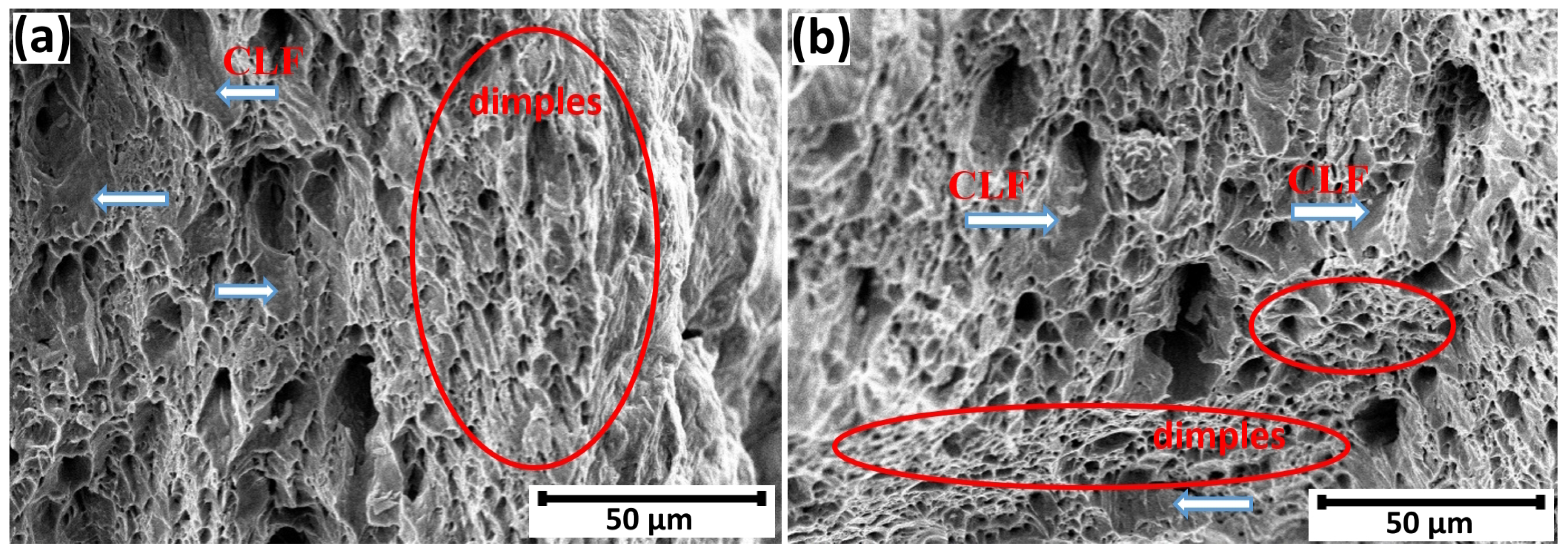
On the fracture surface of specimen H-0 (Figure 3a), ductile fracture (DF) regions predominate and are primarily associated with microvoid coalescence. Isolated cleavage-like facets (CLF), marked by white arrows (Figure 3a,b), are also observed within the specimen’s interior. Well-defined dimpled regions appear both near the outer edges of the fracture surface (Figure 3a) and within the interior (Figure 3b). The CLF zones are estimated to cover approximately 3–5% of the total fracture surface of the specimen after the tensile test. The fracture of H-0 is defined as ductile with isolated quasi-cleavage facets.
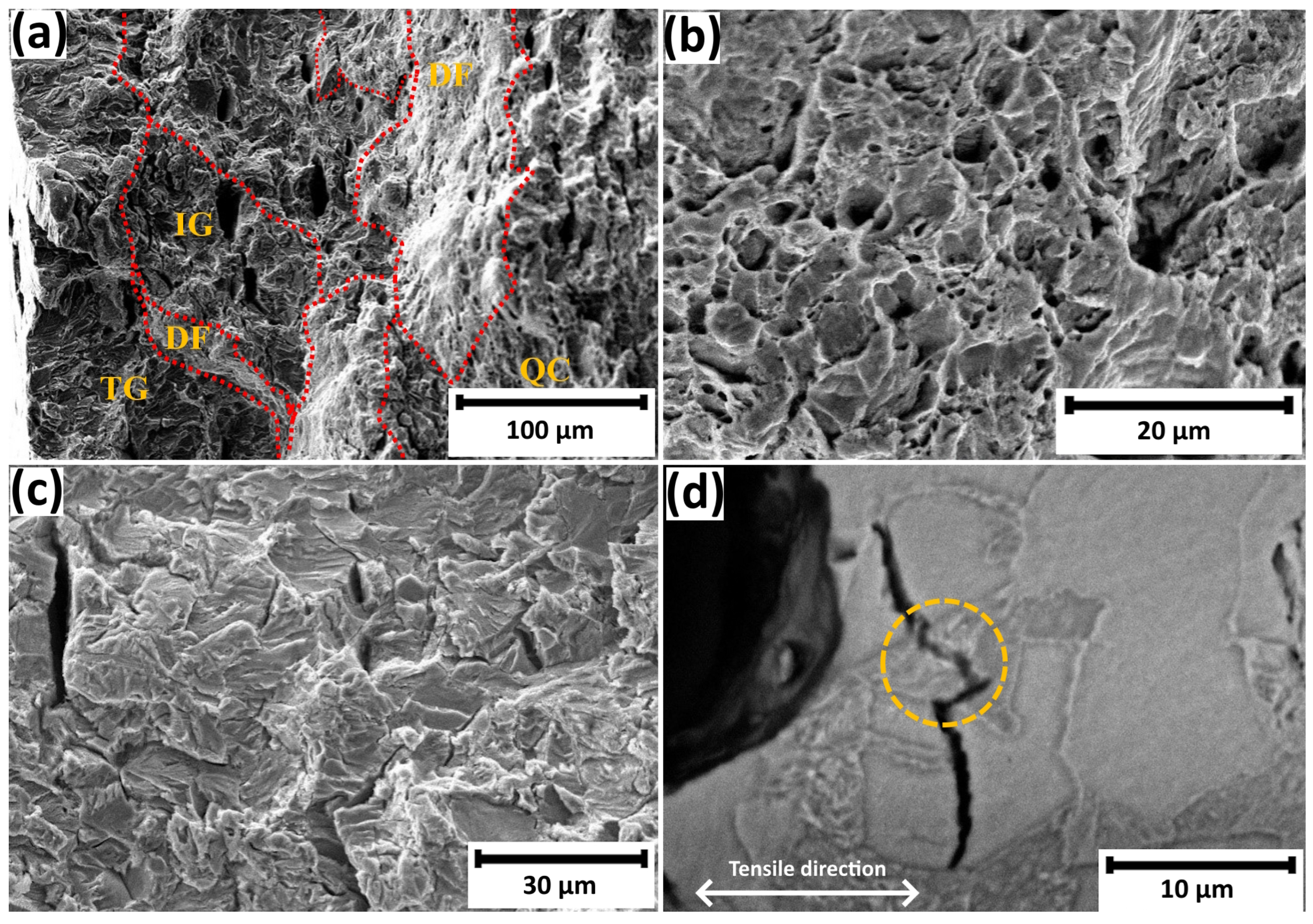
The morphology of the fracture surfaces of the in-situ hydrogen-charged specimens changes significantly after the tensile tests. Well-defined brittle fracture zones develop just beneath the surfaces of specimens H-1, H-24, and H-72 (Figure 4a). These zones coalesce into continuous brittle fracture layers (Figure 4b, Figure 5a and Figure 6a), within which both intergranular and transgranular microcracks are observed. The intergranular cracks (Figure 4a) propagate along grain boundaries between adjacent ferrite/ferrite, pearlite/pearlite, and ferrite/pearlite grains, as well as at triple junctions involving grains of different phases—referred to as triple point cracking (Figure 4a).
The initiation and propagation of stress-oriented hydrogen-induced cracks (SOHICs), both at the surface (Figure 6c) and within the interior of the specimens (Figure 5a,c), are indicative of an enhanced hydrogen concentration. It is well established that crack tips act as stress concentrators, leading to the generation of new dislocations and creating a concentration gradient of hydrogen [24]. This process progresses as a chain reaction, whereby hydrogen accumulation at trap sites and crack tips surpasses the critical concentration threshold, ultimately resulting in quasi-cleavage fractures even in the internal regions of the specimens (Figure 5b).
Our investigations revealed that the hydrogen concentration ( C H ) in the pipe steel remains nearly constant after 1, 24 and 72 h of charging (Table 2). Similar observations have been reported in other studies on low-carbon steels, where hydrogen saturation in specimens with comparable geometry was achieved after only 1 h of charging [25]. Although the charging time has little effect on the overall hydrogen concentration in the metal, a notable change in the fracture surface morphology is observed after tensile testing of specimens charged for 1, 24, and 72 h. The relative area fraction of the brittle fracture zones increases with longer charging times. In specimen H-1, these zones account for approximately 46% of the total fracture surface. Figure 4b clearly shows delamination—TG layers with well-developed facets and QC fragments. According to [26], delamination represents initiation sites for brittle fracture under tensile loading. The brittle fracture layers are separated by layers exhibiting ductile fracture with a fibrous appearance (Figure 4b).
With increasing hydrogen charging time, the size of the brittle fracture zones increases, and their relative area fraction reaches approximately 60% in specimen H-24 and 65% in H-72. The delaminated regions, comprising transgranular and intergranular fracture zones, as well as quasi-cleavage areas, expand accordingly. Delamination is observed both near the surfaces through which hydrogen has diffused and within the interior, around the longitudinal axis of the cross-section (Figure 5a and Figure 6a,b).
The micropores within the ductile fracture zones appear equiaxed, suggesting their formation under conditions of uniform plastic deformation in the direction of the applied tensile stress, which is perpendicular to the plane of observation (Figure 5b). In specimens H-24 and H-72, QC regions are distinctly developed (Figure 5a,b). Both the number and size of cracks within these regions have increased. These changes are attributed not only to the presence of hydrogen but also to its prolonged retention within the metallic matrix.
In the presence of hydrogen, dislocation mobility is enhanced, leading to the formation of zones with locally increased plasticity—an expression of the HELP mechanism [14,15].
Additionally, hydrogen atoms segregate at grain boundaries and along the surfaces of non-metallic inclusions, reducing their adhesion to the metallic matrix [10,11]. In our opinion, prolonged hydrogen charging increases hydrogen occupancy at the boundaries and at the interfaces between different microstructural elements. This accumulation weakens interatomic bonding, lowers the cohesive strength of the interfaces, and activates the HEDE mechanism, leading to the propagation of intergranular cracks.
In addition to promoting intergranular cracking, hydrogen also drives transgranular fracture. A multiscale model integrating a thermodynamic-kinetic continuum framework, cohesive zone modeling, and a quantum-mechanical magnetic tight-binding approximation for interatomic forces, was developed in [27] to describe the time-dependent decohesion process in hydrogen-charged bcc Fe under applied stress. When tensile load is applied, the tetrahedral interstices between the decohering planes become distorted and enlarged. These distorted sites serve as deeper hydrogen traps compared to those in the bulk lattice, driving a flux of hydrogen into the cohesive zone. Simulations reveal a van der Waals–like phase transition from a dilute to a saturated cohesive zone as decohesion progresses. The progressive accumulation of hydrogen weakens the interatomic bonds at the interface, thereby reducing the cohesive strength. Consequently, the loss of interfacial cohesion increases the width of the cohesive zone, making the process self-perpetuating. This behavior, controlled by the magnitude of the applied stress and the rate of hydrogen diffusion from the bulk, ultimately facilitates the propagation of cracks within the ferritic grains.
To assess the effect of prolonged hydrogen charging on the distribution of hydrogen atoms in the ferrite–pearlite structure, hydrogen diffusion coefficients were determined for both cementite and ferrite. Molecular dynamics simulations were performed to calculate these diffusion coefficients by evaluating the mean squared displacement (MSD) of hydrogen atoms within the Fe-C-H system. In our simulations, we employed periodic supercells consisting of 32,700 atoms for ferrite and 46,432 atoms for cementite. A link to molecular dynamic simulation videos can be found in the Supplementary Materials Section 4.
To enable large-scale parallel computations, we employ the ternary Fe-C-H bond-order potential (BOP) developed by Zhou et al. [28], which is implemented in the LAMMPS MD code [29]. This interatomic potential enables stable molecular dynamics simulations of α -Fe, γ -Fe, and cementite (Fe3C), and it provides a reasonable description of hydrogen-related effects within these phases.
The total simulation time for each system was 5 nanoseconds. The hydrogen diffusion coefficients calculated by us in ferrite and cementite are 0.13 × 10 9   m 2 /s and 0.20 ×  10 13   m 2 /s, respectively. The hydrogen diffusivity obtained for ferrite is nearly two orders of magnitude lower than the experimental value reported by Nagano et al. [30], namely 8.98 ×  10 9   m 2 /s. In our opinion, this discrepancy can be attributed to the fact that classical molecular dynamics simulations do not account for quantum tunneling effects, which are significant due to the low mass of hydrogen atoms. These quantum effects effectively reduce the activation energy barrier for hydrogen diffusion in ferrite by approximately a factor of two, leading to higher experimental diffusivities than those predicted by classical molecular dynamics.
The significantly higher calculated diffusion coefficient of hydrogen in the ferrite phase compared to the cementite phase, as calculated by us, supports our hypothesis and conclusions in [31] that hydrogen atoms preferentially migrate and accumulate in the ferritic regions during hydrogen charging. This includes both the bulk ferrite grains and the ferritic lamellae within the pearlite microstructure. Such preferential accumulation plays a critical role in hydrogen-induced damage mechanisms, such as embrittlement and decohesion, which are more likely to initiate and propagate in the ferrite phase due to its higher hydrogen solubility and diffusion kinetics [32]. Furthermore, the mechanical mismatch between ferrite and cementite promotes stress concentration at their interfaces, making the ferrite/cementite boundaries within pearlitic colonies prime sites for microcrack initiation.
The banded distribution of regions exhibiting pure TG and QC fracture (Figure 4b) can be attributed to the banded ferrite-pearlite microstructure of the steel and to the varying defect densities introduced both during the pipe’s service life and during in-situ hydrogen charging. The combined action of the HELP and HEDE mechanisms is believed to promote crack propagation and facilitate the development of quasi-cleavage fracture along the fracture surface [24]. When hydrogen charging and tensile deformation occur simultaneously, the movement of dislocations in ferrite whose mobility increases at higher hydrogen concentrations is blocked by the ferrite-cementite interfaces within pearlite, where the dislocations accumulate. This accumulation alters the interface structure, increases the local hydrogen concentration, and enhances hydrogen solubility within the pearlite [24]. Consequently, the presence of different phases and microstructural features in the steel leads to local variations in hydrogen content. The additional mechanical mismatch between ferrite and cementite, caused by the accumulation of dislocations and elevated hydrogen content at their interface, primarily promotes microcrack initiation at the ferrite-cementite interfaces within pearlitic colonies (Figure 4a and Figure 5c).
In specimen H-72 (Figure 6b), a crack outlined by a dashed line is observed propagating transgranularly across a pearlite colony. Similar microcracks are also visible in specimens H-1 and H-24 (Figure 4a and Figure 5c,d).
Although direct experimental evidence is currently lacking, we propose the following tentative mechanism for this specific crack formation process in pearlite under in-situ hydrogen charging conditions.
Hydrogen promotes dislocation glide in ferrite lamellae according to the HELP mechanism, leading to dislocation pile-up at the ferrite-cementite interfaces within pearlite. Simultaneously (though more slowly due to diffusion-limited processes), hydrogen diffuses into and accumulates at carbon vacancies within the cementite lattice, weakening atomic bonds in accordance with the HEDE mechanism [33]. This process is presented in the appendix, Figure A1. At an appropriate applied tensile stress, this may ultimately cause shear cracking initiated at the ferrite-cementite interface that penetrates both the ferrite and cementite lamellae. The process is likely accelerated under prolonged in-situ hydrogen charging, which provides sufficient time for hydrogen diffusion and dislocation interactions, thereby enabling the full development of this embrittlement mechanism.
Since published data on the deformation and fracture behavior of pearlite in ferrite–pearlite steels under hydrogen charging is still scarce [31], we expect this phenomenon to be the subject of future investigations.
Based on fractographic analysis, we conclude that hydrogen embrittlement consistently initiates with the activation of the HELP mechanism, followed by the onset of HEDE. However, under prolonged hydrogen charging, both mechanisms (HELP and HEDE) act simultaneously, leading to more pronounced and severe manifestations of hydrogen-induced damage.

3.4. TEM Analysis

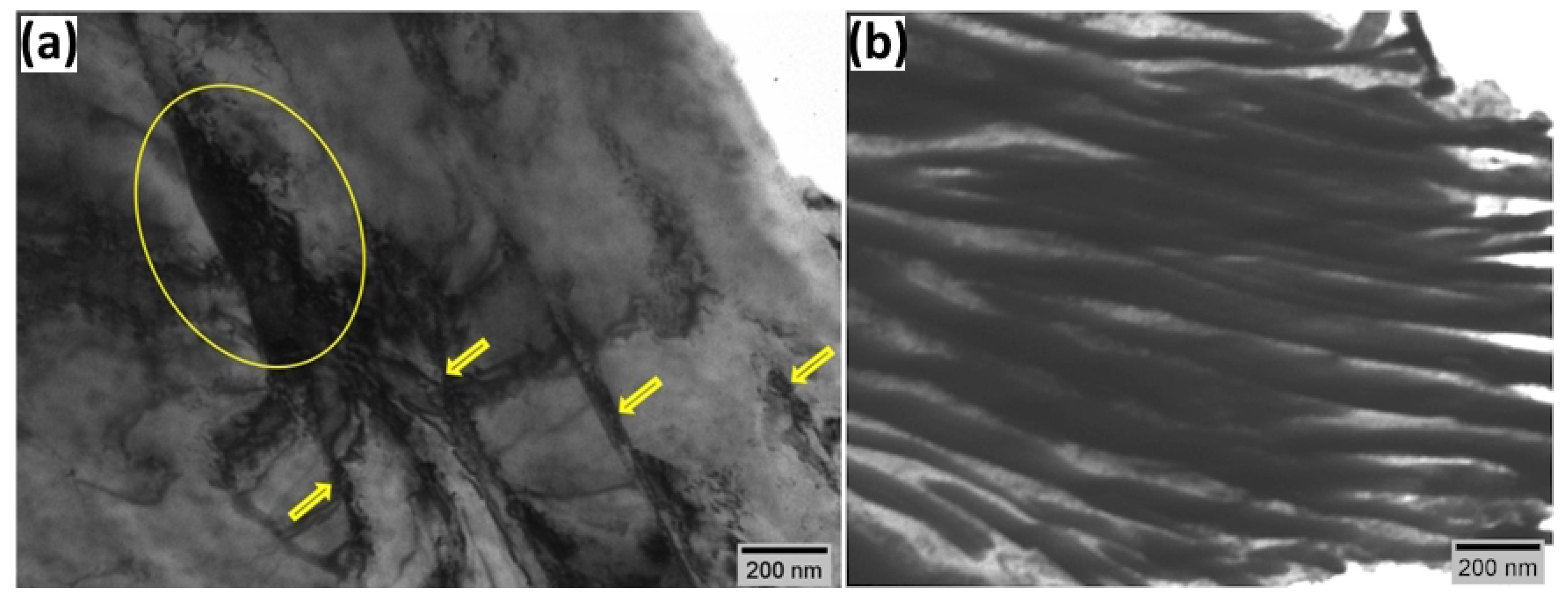
Figure 7 shows the structure of a sample H-0 of steel X52 that had been in service for more than three decades, after a tensile test was conducted, without additional hydrogen charging.
In Figure 7a, slip bands (indicated by arrows) with an average spacing of approximately 280 nm are observed within a ferrite grain, resulting from plastic deformation during tensile testing of the specimen [34]. The dislocation substructure consists mainly of dislocation pile-ups along the boundaries of the slip bands (yellow ellipse). However, the density of these accumulated dislocations is not sufficiently high to provide shear strengthening. Therefore, the deformed structure of sample H-0 is relatively homogeneous, and the plastic mechanism is mainly governed by dislocation shear lines [34].
Figure 7b presents an electron microscopy image of a pearlite colony with lamella thickness ranging from about 22 nm to 77 nm. In the ferritic component of the pearlite, isolated dislocations are present, which are oriented parallel to the length of the lamellae.
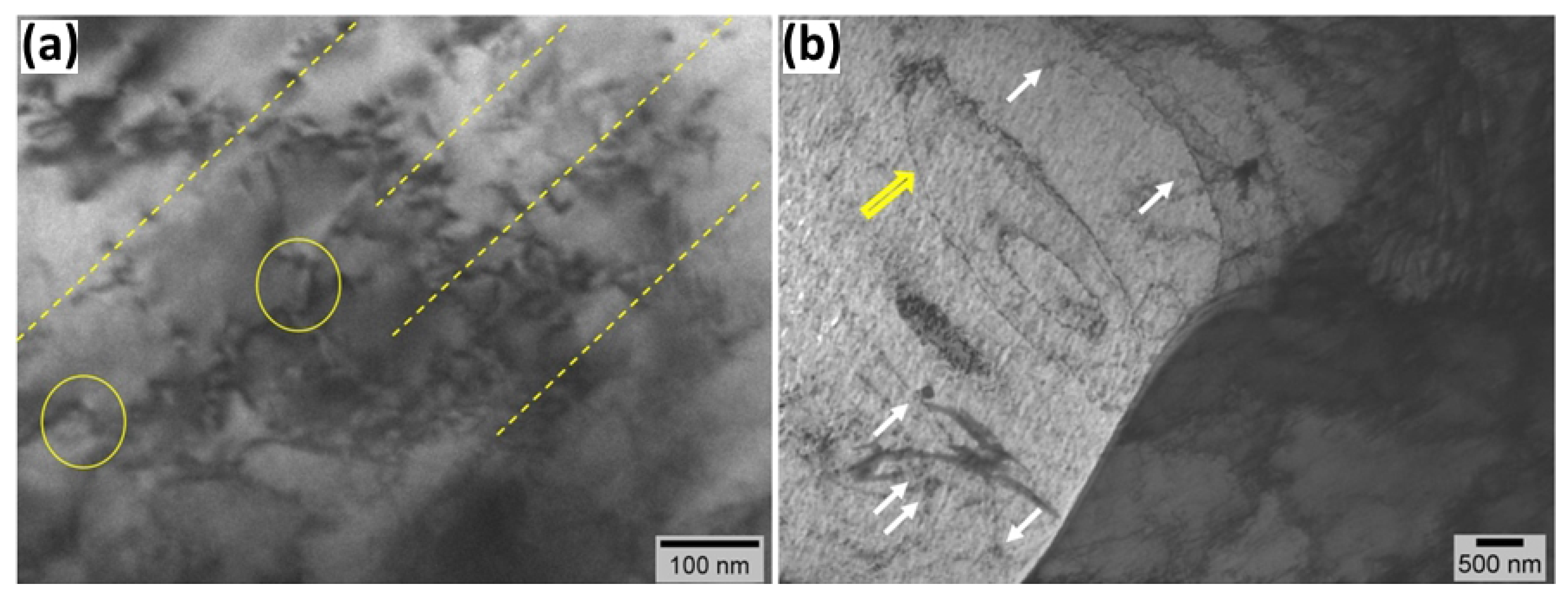
Figure 8 shows the microstructure of a ferrite grain after in-situ hydrogen charging for 1 h. Traces of slip bands (indicated by yellow dashed lines) can be observed, as indicated by the presence of localized accumulation of linear and point defects.
In Figure 8a, dislocations can be observed, with segments moving along parallel slip planes (highlighted with a yellow circle). The segments are separated by pinning points. This configuration of the dislocation line leads to the deviation of dislocation movement outside the primary slip plane.
A well-formed cellular dislocation structure can be observed in Figure 8b, which is a precursor for the formation of low-angle grain boundaries (LAGBs) [35]. In-situ hydrogenation of the material for 1 h leads to the formation of dislocation prismatic loops (white arrows in Figure 8b).
In pure Fe, the dominant 1 2 [111] screw dislocations glide via the thermally activated formation of kink pairs on any of the three {110} intersecting glide planes. The kink migration speed in pure bcc-Fe is sufficiently high that, once a kink pair nucleates, the kinks rapidly separate and reach the ends of the dislocation line before another pair forms, effectively preventing kink collisions. This dynamic changes significantly in the presence of hydrogen. Hydrogen atoms trapped within the dislocation core increase the kink-pair nucleation rate and also exert a solute drag on migrating kinks, reducing their mobility and increasing the probability of collisions between kinks propagating on different glide planes. These collisions result in the formation of sessile edge jogs.
According to a self-consistent kinetic Monte Carlo (SckMC) model developed in [36] to describe the motion of 1 2 [111] screw dislocations in bcc iron, these jogs act as self-pinning points. They drag out edge dipoles, which eventually pinch off to form prismatic loop debris—entirely induced by the interaction between the dislocation and dissolved hydrogen. We observe such prismatic loops and self-pinning points in transmission electron microscopy images of deformed, hydrogen-charged ferrite phases, providing experimental support for the simulation-based predictions (Figure 8). Experimental observations reported in [36] confirmed the predictions of the SCkMC model.
A Frank-Read source can be observed in the ferrite grain (yellow arrow in Figure 8b). Various configurations of Frank-Read sources have been simulated in α -iron at high temperatures [37]. Hydrogen’s effect on dislocation motion and stress fields facilitates the activation of Frank-Read sources and the generation of dislocations at room temperatures. The presence of self-pinning points in transmission electron microscopy images indicates the formation of hydrogen atmospheres within the dislocation cores of hydrogen-charged samples. The hydrogen atmospheres shield dislocation stress fields, reducing dislocation core energy and dislocation-dislocation repulsion [38]. This lowers the critical stress required to activate a Frank-Read source. Increased dislocation mobility allows the bowed segments to expand and loop off more rapidly once activated.
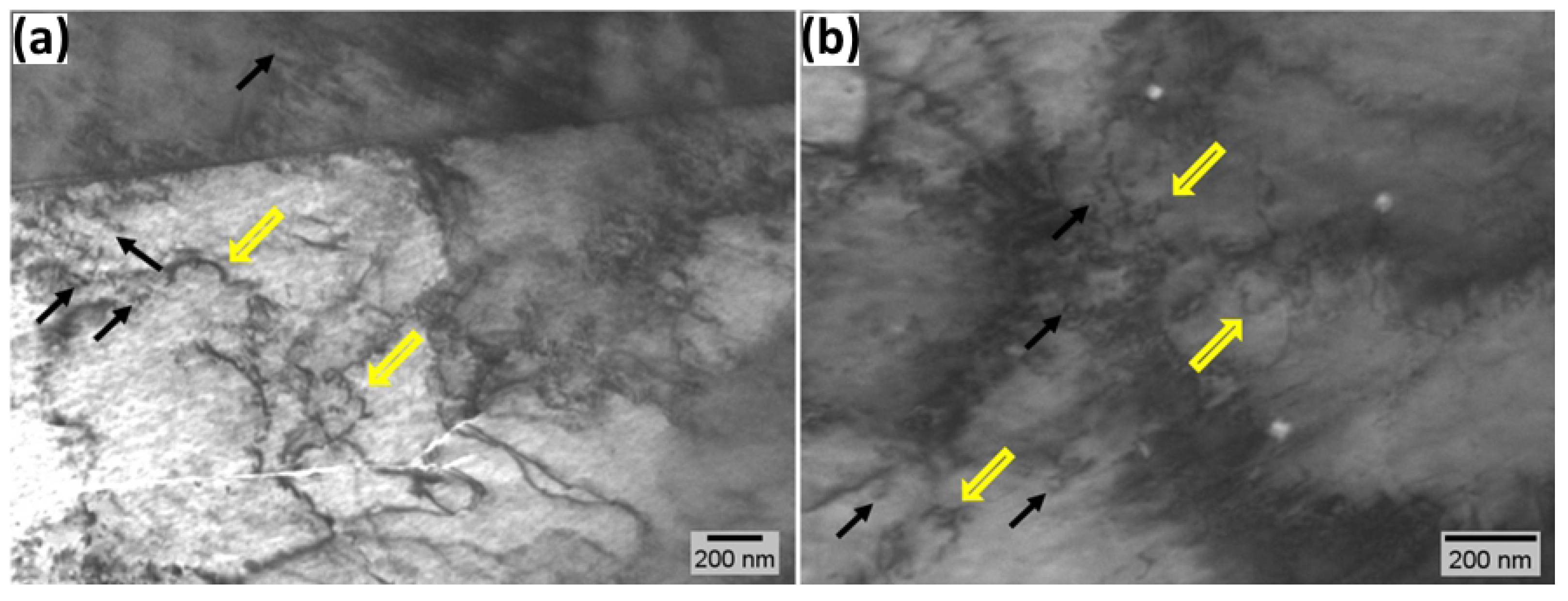
Figure 9a,b show the microstructure of the studied steel after 24 and 72 h of hydrogen charging and tensile loading, respectively. Similar to the 1 h hydrogen charging (Figure 8), the formation of a cellular dislocation structure is observed. In addition, isolated dislocations with pinning points (indicated by yellow arrows) and a large number of prismatic dislocation loops (indicated by black arrows) can be seen in Figure 9. The formation of both dislocations with pinning points along their lines and prismatic loops is caused by the influence of hydrogen, and their number increases with prolonged hydrogen charging times [39].
In the non-charged sample, TEM images indicate the activation of specific slip systems, leading to the formation of parallel, equally spaced slip bands (Figure 7). SCkMC simulations [36] show that the mobility of 1 2 [111] screw dislocations out of the primary slip plane increases after the formation of a hydrogen atmosphere in their cores, leading to the tangling of dislocations within each slip band. To minimize elastic strain energy, dislocations rearrange into walls. Hydrogen-enhanced dislocation mobility enables dislocations to reach low-energy wall configurations more rapidly. The regions between these walls are dislocation-poor, forming a network of cells. Slip bands and dislocation cell structures represent linked stages in the process by which hydrogen induces the rearrangement from an early-stage localized slip to an energy-minimized dislocation configuration. The lower activation stress for Frank-Read sources in hydrogen-charged samples, which leads to a higher dislocation density, further promotes the rearrangement of dislocations into cell walls and the formation of a cell structure.
Figure 10 shows the structural changes in pearlite in the presence of hydrogen. After 1 h of charging, the ferrite component of pearlite is mostly free of structural defects (indicated by a dashed circle in Figure 10a), with only individual dislocations observed (marked with a circle in Figure 10a). Consequently, in Figure 10b,c, for charging times of 24 and 72 h, a certain localization of dislocation bands can be seen (indicated by arrows), almost perpendicular to the cementite component of pearlite. In agreement with the results obtained from SEM microscopy, the present TEM images also indicate that the transverse dislocation bands formed in the ferrite lamellae weaken the cohesive strength of the ferrite-cementite interface and initiate the formation of transgranular cracks through the ferrite and cementite lamellae.

4. Conclusions

This study investigates the effect of hydrogen charging time on the mechanical properties and microstructural evolution of low-carbon ferrite-pearlite steel that has been in service for over 30 years in natural gas transmission. By combining in-situ electrochemical hydrogen charging from 1 to 72 h with tensile testing, SEM, TEM, and molecular dynamics simulations, we obtained insights into the microstructural evolution, deformation mechanisms, and crack initiation processes in this steel in the presence of hydrogen. Based on these findings, the following conclusions can be drawn:
  • Although charging time had little effect on the overall hydrogen concentration and strength characteristics in the metal, pronounced time-dependent changes in plasticity, fracture morphology and microstructure were observed after tensile testing of specimens charged for 1, 24, and 72 h.
  • Fractographic analysis revealed a transition from ductile fracture in uncharged specimens to a predominance of brittle fracture modes (quasi-cleavage, intergranular, and transgranular) in hydrogen-charged samples. The relative area fraction of brittle fracture zones increased from 46% to 65% with an increase in loading time from 1 to 72 h.
  • The present microstructural investigations indicated an initial plastic failure in the ferrite grains and then, with an increase in hydrogen charging time, failure at the ferrite–cementite interface.
  • TEM analysis of hydrogen-charged ferrite phases further indicates that prolonged charging leads to localized plasticity, dislocation pinning, and the formation of prismatic loop debris, which can be explained by enhanced hydrogen trapping at ferrite-cementite interfaces, grain boundaries, and the formation of hydrogen atmospheres within the dislocation cores. The number of pinned dislocations and prismatic loops increases with increasing hydrogen charging time. Hydrogen facilitates the activation of Frank-Read sources and the generation of dislocations.
  • In the non-charged sample, TEM images show activation of slip bands. Hydrogen exposure increases the mobility of dominant screw dislocations outside the primary slip plane, leading to tangling within slip bands. To minimize elastic strain energy, dislocations rearrange into walls, forming a cellular network. The slip bands and dislocation cells represent sequential stages in hydrogen-induced rearrangement from localized slip to an energy-minimized dislocation configuration.

Supplementary Materials

The following supporting molecular dynamic simulation videos can be downloaded at: https://www.mdpi.com/article/10.3390/met15101079/s1, Simulation of hydrogen diffusion in bcc iron: A2.mp4; Simulation of hydrogen diffusion in cementite: A3.mp4

Author Contributions

Conceptualization, I.K., V.D. and R.L.; methodology, V.D., B.Y., K.V., Y.M. and R.K.; software, I.K., T.S. and K.K.; validation, I.K., V.D. and R.L.; formal analysis, V.D., B.Y., R.L. and R.K.; investigation, V.D., B.Y., Y.M., K.V. and R.K.; resources, R.L., V.D., B.Y. and I.K.; data curation, V.D. and B.Y.; writing—original draft preparation, V.D., K.K., B.Y. and R.L.; writing—review and editing, K.K., V.D. and R.L.; visualization, K.K. and T.S.; supervision, I.K. and R.L.; project administration, I.K. and T.S.; funding acquisition, I.K. and T.S. All authors have read and agreed to the published version of the manuscript.

Funding

This research was financially supported by the National Recovery and Resilience Fund (RRF) of Bulgaria (Project PVU-51/BG-RRP-2.017-0022-C02).

Data Availability Statement

The original contributions presented in the study are included in the article; further inquiries can be directed to the corresponding author.

Acknowledgments

(1) The work in this publication was performed using equipment funded by project BG16RFPR002-1.014-0006 “National Center for Mechatronics and Clean Technologies”. (2) We acknowledge Lyudmil Drenchev and Lyudmil Lyutov for the theoretical discussions that contributed to the improvement of this study. (3) We appreciate the help and positive contributions of Lisa Claeys, Tom Depover, Kim Verbeken from the Department of Materials Science and Engineering, Ghent University (UGent), Belgium.

Conflicts of Interest

The authors declare no conflicts of interest.

Appendix A

In Figure A1, we have schematically presented what, in our opinion, happens in ferrite and pearlite with increasing charging time under in-situ conditions. Hydrogen promotes dislocation slip in ferrite lamellae according to the HELP mechanism. At the same time (although more slowly due to diffusion-limited processes), hydrogen diffuses and accumulates in carbon vacancies in the cementite lattice, weakening atomic bonds according to the HEDE mechanism.
Figure A1. Schematic representation of the effect of hydrogen on the propagation of defects in ferrite and pearlite with increasing charging time under in-situ conditions.
Metals 15 01079 g0a1

References

  1. Djukic, M.B.; Bakic, G.M.; Zeravcic, V.S.; Sedmak, A.; Rajicic, B. Hydrogen embrittlement of industrial components: Prediction, prevention, and models. Corrosion 2016, 72, 943–961. [Google Scholar] [CrossRef]
  2. Barrera, O.; Bombac, D.; Chen, Y.; Daff, T.; Galindo-Nava, E.; Gong, P.; Haley, D.; Horton, R.; Katzarov, I.; Kermode, J.R.; et al. Understanding and mitigating hydrogen embrittlement of steels: A review of experimental, modelling and design progress from atomistic to continuum. J. Mater. Sci. 2018, 53, 6251–6290. [Google Scholar] [CrossRef]
  3. Ali, M.; Ul-Hamid, A.; Alhems, L.M.; Saeed, A. Review of common failures in heat exchangers—Part I: Mechanical and elevated temperature failures. Eng. Fail. Anal. 2020, 109, 104396. [Google Scholar] [CrossRef]
  4. Adasooriya, N.D.; Tucho, W.M.; Holm, E.; Årthun, T.; Hansen, V.; Solheim, K.G.; Hemmingsen, T. Effect of hydrogen on mechanical properties and fracture of martensitic carbon steel under quenched and tempered conditions. Mater. Sci. Eng. A 2021, 803, 140495. [Google Scholar] [CrossRef]
  5. Wasim, M.; Djukic, M.B. Hydrogen embrittlement of low carbon structural steel at macro-, micro-and nano-levels. Int. J. Hydrogen Energy 2020, 45, 2145–2156. [Google Scholar] [CrossRef]
  6. Norouzi, E.; Miresmaeili, R.; Shahverdi, H.R.; Askari-Paykani, M.; Vergani, L.M. Effect of hydrogen on the microstructure and mechanical properties of FeCCrNiBxSi advanced high strength steels. Corros. Sci. 2024, 230, 111897. [Google Scholar] [CrossRef]
  7. Drímalová, P.; Nový, F.; Medvecká, D.; Váňová, P. The Influence of Hydrogen Embrittlement on Mechanical Properties of Advanced High-Strength Structural Steel S960MC. In Quality Production Improvement and System Safety: QPI 16-CZOTO 10; Materials Research Forum LLC: Lancaster County, PA, USA, 2023; Volume 34, p. 62. [Google Scholar]
  8. Djukic, M.B.; Zeravcic, V.S.; Bakic, G.M.; Sedmak, A.; Rajicic, B. Hydrogen damage of steels: A case study and hydrogen embrittlement model. Eng. Fail. Anal. 2015, 58, 485–498. [Google Scholar] [CrossRef]
  9. Tau, L.; Chan, S. Effects of ferrite/pearlite alignment on the hydrogen permeation in a AISI 4130 steel. Mater. Lett. 1996, 29, 143–147. [Google Scholar] [CrossRef]
  10. Laureys, A.; Pinson, M.; Claeys, L.; Deseranno, T.; Depover, T.; Verbeken, K. Initiation of hydrogen induced cracks at secondary phase particles. Fract. Struct. Integr. 2020, 14, 113–127. [Google Scholar] [CrossRef]
  11. Laureys, A.; Depraetere, R.; Cauwels, M.; Depover, T.; Hertelé, S.; Verbeken, K. Use of existing steel pipeline infrastructure for gaseous hydrogen storage and transport: A review of factors affecting hydrogen induced degradation. J. Nat. Gas Sci. Eng. 2022, 101, 104534. [Google Scholar] [CrossRef]
  12. Elboujdaini, M. Hydrogen-induced cracking and sulfide stress cracking. In Uhlig’s Corrosion Handbook; Wiley: Hoboken, NJ, USA, 2011; Volume 3, pp. 183–194. [Google Scholar]
  13. Outokumpu Oyj. Handbook of Stainless Steel; Outokumpu Oyj: Helsinki, Finland, 2013. [Google Scholar]
  14. Gangloff, R.P.; Somerday, B.P. Gaseous Hydrogen Embrittlement of Materials in Energy Technologies: The Problem, Its Characterisation and Effects on Particular Alloy Classes; Elsevier: Amsterdam, The Netherlands, 2012. [Google Scholar]
  15. Troiano, A.R. The Role of Hydrogen and Other Interstitials in the Mechanical Behavior of Metals: (1959 Edward de Mille Campbell Memorial Lecture); Springer: Berlin/Heidelberg, Germany, 2016. [Google Scholar]
  16. Boot, T.; Riemslag, T.; Reinton, E.; Liu, P.; Walters, C.L.; Popovich, V. In-situ hollow sample setup design for mechanical characterisation of gaseous hydrogen embrittlement of pipeline steels and welds. Metals 2021, 11, 1242. [Google Scholar] [CrossRef]
  17. Wan, H.J.; Wu, X.Q.; Ming, H.L.; Wang, J.Q.; Han, E.H. Effects of hydrogen charging time and pressure on the hydrogen embrittlement susceptibility of X52 pipeline steel material. Acta Metall. Sin. (Engl. Lett.) 2024, 37, 293–307. [Google Scholar] [CrossRef]
  18. Laureys, A.; Van den Eeckhout, E.; Petrov, R.; Verbeken, K. Effect of deformation and charging conditions on crack and blister formation during electrochemical hydrogen charging. Acta Mater. 2017, 127, 192–202. [Google Scholar] [CrossRef]
  19. Djukic, M.B.; Bakic, G.M.; Zeravcic, V.S.; Sedmak, A.; Rajicic, B. The synergistic action and interplay of hydrogen embrittlement mechanisms in steels and iron: Localized plasticity and decohesion. Eng. Fract. Mech. 2019, 216, 106528. [Google Scholar] [CrossRef]
  20. Sobola, D.; Dallaev, R. Exploring hydrogen embrittlement: Mechanisms, consequences, and advances in metal science. Energies 2024, 17, 2972. [Google Scholar] [CrossRef]
  21. ISO 17081:2014(E); Method of Measurement of Hydrogen Permeation and Determination of Hydrogen Uptake and Transport in Metals by an Electrochemical Technique. International Organization for Standardization: Geneva, Switzerland, 2014.
  22. Yanachkov, B.; Mourdjeva, Y.; Valuiska, K.; Dyakova, V.; Kolev, K.; Kaleicheva, J.; Lazarova, R.; Katzarov, I. Effect of Hydrogen Content on the Microstructure, Mechanical Properties, and Fracture Mechanism of Low-Carbon Lath Martensite Steel. Metals 2024, 14, 1340. [Google Scholar] [CrossRef]
  23. Yanachkov, B.; Lyutov, L.; Katzarov, I.; Drenchev, L.; Kolev, K. Effect of Microstructure on the Mechanical Response of Hydrogen-Charged Pure Iron. Metals 2022, 12, 2160. [Google Scholar] [CrossRef]
  24. Oh, D.K.; Jeong, M.S.; Shin, S.H.; Hwang, B. Effect of Hydrogen on Tensile Properties and Fracture Behavior of Two High-Strength American Petroleum Institute Linepipe Steels. Metals 2024, 14, 1397. [Google Scholar] [CrossRef]
  25. Pinson, M.; Springer, H.; Depover, T.; Verbeken, K. The effect of quench cracks and retained austenite on the hydrogen trapping capacity of high carbon martensitic steels. Int. J. Hydrogen Energy 2021, 46, 16141–16152. [Google Scholar] [CrossRef]
  26. Nykyforchyn, H.; Zvirko, O.; Dzioba, I.; Krechkovska, H.; Hredil, M.; Tsyrulnyk, O.; Student, O.; Lipiec, S.; Pala, R. Assessment of operational degradation of pipeline steels. Materials 2021, 14, 3247. [Google Scholar] [CrossRef] [PubMed]
  27. Katzarov, I.H.; Paxton, A.T. Hydrogen embrittlement II. Analysis of hydrogen-enhanced decohesion across (111) planes in α-Fe. Phys. Rev. Mater. 2017, 1, 033603. [Google Scholar] [CrossRef]
  28. Zhou, X.; Foster, M.E.; Ronevich, J.A.; San Marchi, C.W. Review and construction of interatomic potentials for molecular dynamics studies of hydrogen embrittlement in Fe-C based steels. J. Comput. Chem. 2020, 41, 1299–1309. [Google Scholar] [CrossRef] [PubMed]
  29. Thompson, A.P.; Aktulga, H.M.; Berger, R.; Bolintineanu, D.S.; Brown, W.M.; Crozier, P.S.; In’t Veld, P.J.; Kohlmeyer, A.; Moore, S.G.; Nguyen, T.D.; et al. LAMMPS-a flexible simulation tool for particle-based materials modeling at the atomic, meso, and continuum scales. Comput. Phys. Commun. 2022, 271, 108171. [Google Scholar] [CrossRef]
  30. Nagano, M.; Hayashi, Y.; Ohtani, N.; Isshiki, M.; Igaki, K. Hydrogen diffusivity in high purity alpha iron. Scr. Metall. 1982, 16, 973–976. [Google Scholar] [CrossRef]
  31. Niu, R.; Li, H.; Liu, P.Y.; Burr, P.; Feng, Y.; Yen, H.W.; Huang, C.; Sun, Y.H.; Ma, M.; Guo, A.; et al. Hydrogen-enhanced deformation in pearlite. Acta Mater. 2024, 281, 120327. [Google Scholar] [CrossRef]
  32. Song, Y.; Han, Z.; Chai, M.; Yang, B.; Liu, Y.; Cheng, G.; Li, Y.; Ai, S. Effect of cementite on the hydrogen diffusion/trap characteristics of 2.25 Cr-1Mo-0.25 V steel with and without annealing. Materials 2018, 11, 788. [Google Scholar] [CrossRef] [PubMed]
  33. Ogawa, Y.; Hino, M.; Nakamura, M.; Matsunaga, H. Pearlite-driven surface-cracking and associated loss of tensile ductility in plain-carbon steels under exposure to high-pressure gaseous hydrogen. Int. J. Hydrogen Energy 2021, 46, 6945–6959. [Google Scholar] [CrossRef]
  34. Jia, Y.; Ren, C.; Wu, S.; Mu, Y.; Xu, L.; Jia, Y.; Yan, W.; Yi, J.; Wang, G. Multistage strain-hardening behavior of ultrastrong and ductile lightweight refractory complex-concentrated alloys. J. Mater. Sci. Technol. 2023, 149, 73–87. [Google Scholar] [CrossRef]
  35. Du, X.; Zhou, L.; Li, J.; Xie, Z.; Li, S.; Xiao, H.; Li, M.; Zhao, Y. Achieving high strength and low yield ratio by constructing the network martensite-ferrite heterogeneous in low carbon steels. Mater. Sci. Eng. A 2025, 920, 147526. [Google Scholar] [CrossRef]
  36. Gong, P.; Katzarov, I.H.; Nutter, J.; Paxton, A.T.; Rainforth, W.M. The influence of hydrogen on plasticity in pure iron-theory and experiment. Sci. Rep. 2020, 10, 10209. [Google Scholar] [CrossRef]
  37. Fitzgerald, S.; Aubry, S.; Dudarev, S.; Cai, W. Dislocation dynamics simulation of Frank-Read sources in anisotropic α-Fe. Model. Simul. Mater. Sci. Eng. 2012, 20, 045022. [Google Scholar] [CrossRef]
  38. Zheng, Z.; Liang, S.; Huang, M.; Zhao, L.; Zhu, Y.; Li, Z. Studying the effects of hydrogen on dislocation mobility and multiplication in nickel by phase-field method. Mech. Mater. 2022, 173, 104443. [Google Scholar] [CrossRef]
  39. Caillard, D.; Legros, M.; Couret, A. Extrinsic obstacles and loop formation in deformed metals and alloys. Philos. Mag. 2013, 93, 203–221. [Google Scholar] [CrossRef]
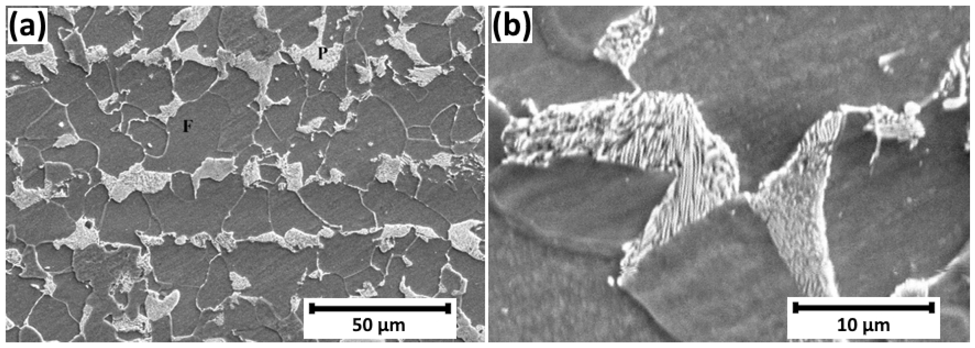
Figure 1. SEM micrograph showing the microstructure of the investigated steel X52 at two magnifications.
Metals 15 01079 g001
Figure 2. Stress–strain curves of the studied specimens.
Metals 15 01079 g002
Figure 3. Fractured surface of a specimen H-0: (a,b) zones, showing dimples and cleavage-like facets (CLFs).
Metals 15 01079 g003
Figure 4. Fractured surface of a specimen H-1: (a) Brittle fracture zone with intergranular (IG) and transgranular (TG) cracks; (b) parallel layers exhibiting ductile fracture with a fibrous appearance (DF), brittle transgranular fracture with well-defined cleavage facets (TG) and quasi-cleavage (QC) zones.
Metals 15 01079 g004
Figure 5. Fractured surface of a specimen H-24: (a) transgranular (TG), intergranular (IG), quasi-cleavage (QC) and ductile fracture (DF) zones with a fibrous appearance; (b) QC zone; (c) brittle fracture (BF) zone with clearly defined SONICs, intergranular (IG) and transgranular (TG) cracks; (d) transgranular crack through ferrite grains and across pearlite lamellae.
Metals 15 01079 g005
Figure 6. Fractured surface of a specimen H-72: (a) QC, IG, TG and DF bands with a fibrous appearance; (b) transgranular crack across a pearlite lamellae; (c) stress-oriented hydrogen-induced cracks.
Metals 15 01079 g006
Figure 7. TEM images of sample H-0, X52 steel after 31 years of service: (a) ferrite grain and (b) pearlite.
Metals 15 01079 g007
Figure 8. TEM images of the microstructure of sample H-1.
Metals 15 01079 g008
Figure 9. TEM images of the microstructure of X52 steel: (a) sample H-24 and (b) sample H-72.
Metals 15 01079 g009
Figure 10. TEM images of pearlite in X52 steel (a) H-1; (b) H-24 and (c) H-72.
Metals 15 01079 g010
Table 1. Chemical composition of the investigated steel.
ElementCSiMnSPCrCuNi
Wt. %0.1540.481.300.0160.0140.020.070.03
Table 2. Hydrogen concentration in the studied specimens.
Specimen No.Hydrogen Charging Conditions
(Electrolyte, Current Density,
Charging Time)
Hydrogen Concentration, [wppm]
H*-0without hydrogen charging1.13 ± 0.20
H*-10.5 M H2SO4, 5 mA/ cm 2 , 1 h4.04 ± 0.13
H*-240.5 M H2SO4, 5 mA/ cm 2 , 24 h4.01 ± 0.67
H*-720.5 M H2SO4, 5 mA/ cm 2 , 72 h3.85 ± 0.61
Table 3. Data from the stress–strain test of the specimens H-0, H-1, H-24 and H-72. R m —tensile strength; A g —plastic extension at the maximum stress; A t —total extension at the end of recorded diagram.
Specimen No. R m , [MPa] A g , [%] A t ( corr . ) , [%]
H-054012.918.9
H-15548.19.7
H-245528.29.6
H-725608.710.0
Disclaimer/Publisher’s Note: The statements, opinions and data contained in all publications are solely those of the individual author(s) and contributor(s) and not of MDPI and/or the editor(s). MDPI and/or the editor(s) disclaim responsibility for any injury to people or property resulting from any ideas, methods, instructions or products referred to in the content.