Article

High-Performance Porous Aluminum Alloys from Recycled A356 Scrap: Synergistic Foaming Approach Using TiH2 and Na2B4O7·10H2O

Interdisciplinary Major of Maritime AI Convergence, Department of Advanced Materials Convergence Engineering, National Korea Maritime and Ocean University, Busan 49112, Republic of Korea
*
Author to whom correspondence should be addressed.
Metals 2025, 15(10), 1068; https://doi.org/10.3390/met15101068
Submission received: 22 August 2025 / Revised: 17 September 2025 / Accepted: 22 September 2025 / Published: 24 September 2025

Abstract

Porous aluminum alloys are widely used for lightweight structural materials such as marine structures, energy absorbers, and buoyant components. However, the conventional foaming agent TiH2 presents limitations such as high cost and elevated decomposition temperatures, which increase manufacturing costs and restrict industrial applicability. In addition, the utilization of recycled raw materials such as aluminum machining chips has emerged as an important challenge in material development for resource efficiency and sustainability. To address these issues, porous aluminum alloys were fabricated in this study using recycled A356 aluminum chips by incorporating TiH2 and a low-cost alternative foaming agent, Na2B4O7·10H2O (borax), either individually or in combination. The effects of foaming agent content (1, 1.5, and 3 wt.%) on pore characteristics, microstructure, hardness, and corrosion resistance were systematically investigated. TiH2 induced an increase in porosity due to hydrogen generation and also promoted grain refinement, which contributed to the improvement of hardness and corrosion resistance, while Na2B4O7·10H2O exhibited effective pore formation and hardness improvement at 1–1.5 wt.% but tended to deteriorate corrosion resistance as its content increased. In particular, combined addition of both agents at 1.5 wt.% showed excellent pore formation and corrosion resistance properties, with a relatively high pore area fraction (2.38%), porosity (27.0%), SDAS (48.1 ± 4.8 µm), hardness (59.35 ± 6.4 HV), corrosion potential (−1.039 V), pitting potential (−0.709 V), and corrosion current density (4.956 μA/cm2). This study demonstrated that Na2B4O7·10H2O (borax) foaming agent can be an economic alternative to TiH2, and shows that the performance of porous aluminum alloys can be effectively improved by optimizing the combination of recycled raw materials and foaming agents.

1. Introduction

Offshore structures are continuously exposed to harsh and complex environments such as saltwater, wet/dry cycles, and irregular loading, which accelerate degradation mechanisms such as corrosion, fatigue cracking, and wear [1,2,3]. These factors significantly affect the service life and structural reliability of offshore structures. Corrosion has emerged as the primary cause of degradation in recent studies, with the potential to induce early structural failure or severe damage [4,5]. In particular, due to the nature of marine environments where maintenance is difficult, materials used in such structures must be evaluated not only for corrosion resistance, light weight, and durability, but also for cost-effectiveness [2,6].
Porous metals are attracting attention as materials that can meet these requirements. Their internal pore structure allows for weight reduction, and their large specific surface area enables them to effectively absorb impact energy and rapidly transfer heat [7,8]. Owing to these excellent properties, porous metals can be applied to various industrial fields, including structural components, crash energy absorbers, sound and vibration dampers, and buoyancy materials [9,10,11].
Such porous aluminum alloys can be produced through various processes, including casting, powder metallurgy, gas injection into molten metal, and metal foaming using foaming agents [12,13,14,15]. In particular, Al–Si alloy foams fabricated using TiH2 as a foaming agent have been reported and evaluated for their potential as lightweight core materials [16].
Among these, hydride-based foaming agents, ZrH2 and TiH2, provide high foaming efficiency, but they have the disadvantages of high cost, wide temperature range for hydrogen release and long heating time, which increases cost and fire hazard [17]. Therefore, there is a need to develop low-cost alternative foaming agents, and at the same time, attention is focused on the design of environmentally friendly and economical alloys utilizing recycled metal raw materials.
Among porous metal materials, aluminum has recently attracted attention, and it is widely used in the manufacture of porous structures due to its excellent castability, mechanical strength, low density, and melting temperature [18,19,20,21,22]. In addition, the demand for recycled materials using aluminum scrap is increasing due to the strengthening of environmental regulations and the growing interest of industries in resource circulation. Among them, aluminum machining chips, which are generated in large quantities during machining processes such as turning and drilling, have a large specific surface area due to their thin and irregular shape, can be easily remelted, are suitable as a recycling material, and are attracting attention as an economical material due to their low cost compared to raw materials. Recycling one ton of aluminum scrap can reportedly save up to 8 tons of bauxite, 14,000 kWh of energy, 6300 L of petroleum, and 7.6 m3 of landfill space, while reducing greenhouse gas emissions to approximately 350 kg CO2 [23,24,25,26,27].
In this study, A356 aluminum machining chips from industrial processes was utilized as a recycled raw material, and a porous aluminum alloy was prepared by adding Na2B4O7·10H2O, a low-cost alternative foaming agent, either alone or combination with TiH2. In general, scrap-based aluminum is prone to pore formation due to residual impurities, which may be advantageous for achieving porous structures [28]. Na2B4O7·10H2O can contribute to the formation of pore structure through its reaction with hydrogen and oxygen in molten aluminum and is evaluated as an alternative to reduce the dependence on hydride-based foaming agents. Therefore, porous alloys were prepared by applying different foaming agent combinations (1, 1.5, 3 wt.%) and the resulting pore properties, microstructure, hardness, and corrosion resistance were quantitatively evaluated. The results demonstrate the potential of Na2B4O7·10H2O as a foaming agent and provide an economic and environmental design strategy for recycling-based alloys.

2. Materials and Methods

2.1. Materials Preparation

A356 aluminum machining chips were compacted into scrap packs, then heat treated at 500 °C for 1.5 h to remove residual cutting oil and prevent fire hazard, and then melted at 800 °C. To promote pore formation, no degassing or stirring procedures were applied.
TiH2 foaming agent addition in the range of 1–1.5 wt.% is generally reported to be the optimal level, but in this study, 1, 1.5, and 3 wt.% were set to quantitatively analyze the effect of foaming agent content on porosity, microstructure, mechanical properties, and corrosion resistance. In addition, Na2B4O7·10H2O (borax) was applied at equal contents (1, 1.5, and 3 wt.%) to evaluate its potential as an alternative foaming agent. For the combined conditions, the total content of foaming agents was set to 1, 1.5, and 3 wt.%, with TiH2 and borax added in equal proportions (e.g., 0.75 wt.% TiH2 + 0.75 wt.% borax for the 1.5 wt.% condition). The reference condition was an as-cast aluminum scrap alloy with no added foaming agent, and a total of 10 specimen conditions were constructed to systematically analyze the behavior of porous aluminum alloys with changes in foaming agent type and content.
The powdered foaming agents were pre-placed in the molds according to their content, and then the melt was injected. To initiate the foaming reaction, the mold was maintained at high temperature for 30 s, followed by solidification under a reduced pressure of 0.8 atm for 240 s. The reduced pressure was applied using a commercial reduced-pressure solidification unit (Furnace System Korea Co., Yangsan, Republic of Korea), which automatically decreases the pressure to the preset value (0.8 atm) and maintains it.
The chemical composition of each specimen was analyzed using laser inductively induced spectroscopy (LIBS, Z-903 geochem, SciAps, Andover, MA, USA), and the main elemental contents are presented in Table 1.

2.2. Microstructure Characterization

The phase length, area fraction, and microstructural observations of the reduced pressure test specimens were conducted using a field-emission scanning electron microscope (FE-SEM, CLARA, TESCAN, Brno, Czech Republic) equipped with an energy-dispersive spectrometer (EDS, EDAX, CLARA, TESCAN, Brno, Czech Republic) at an accelerating voltage of 15 kV. Specimens were mechanically polished using SiC papers (#220–2000), followed by diamond suspensions (3, 1, and 0.25 μm, Struers ApS, Ballerup, Denmark) and colloidal silica (0.04 μm) for final polishing. Porosity was quantitatively analyzed on the surface of reduced-pressure solidified specimens using ImageJ software (version 1.8.0, National Institutes of Health, Bethesda, MD, USA).
Secondary dendrite arm spacing (SDAS) was measured using optical microscopy (Axio Imager 2, Carl Zeiss, Jena, Germany) and the Intercept Method, and was calculated as the average of three measurements in each of five regions per sample. The calculation is given in Equation (1).
S D A S = L n 1
where L is the length of the measuring line, n is the average number of intersections of the line with the grain boundary.
The corrosion products formed on the surface after the immersion test were analyzed using an X-ray diffractometer (Rigaku D/MAX-2100 H, Rigaku, Tokyo, Japan) with Cu Kα lines in the range of 10–90°.

2.3. Density and Porosity Measurement

The porosity of the specimens was determined based on Archimedes’ principle. The actual density ( ρ sample ) was measured using a density balance (TWS-300K, Matsuhaku, Tokyo, Japan) by recording the dry weight in air ( W a i r ) and the weight in distilled water ( W w a t e r ). The density was calculated as follows:
ρ sample = W a i r W a i r W w a t e r × ρ water
The porosity (Porosity, %) was then calculated by comparing the measured density with the theoretical density of the A356 alloy ( ρ _theoretical = 2.68 g/cm3), according to the following equation:
P o r o s i t y ( % ) = ( 1 ρ sample ρ theortical ) × 100

2.4. Evaluation of Mechanical and Corrosion Properties

Microhardness measurements were performed using a Vickers microhardness tester (HM-122, Akashi Co., Tokyo, Japan) under a load of 0.1 kgf with a dwell time of 10 s. For each specimen, ten indentations were taken, and the average value was reported.
Corrosion resistance evaluation was performed by immersion testing and Cyclic Potentiodynamic Polarization (CPDP). To evaluate the resistance of metals to localized corrosion, CPDP was performed at a rate of 0.1 mV/s from −500 mV to +1100 mV in a 3.5 wt.% NaCl solution at room temperature using an electrochemical potentiostat (Interface 1010E Potentiostat, Gamry Instruments, Warminster, PA, USA). A three-electrode electrochemical system was used, consisting of a saturated calomel electrode (SCE) as the reference electrode, platinum as the counter electrode, and the test specimen as the working electrode. The electrochemical data was analyzed using Gamry Echem Analyst software (Version 7.9.0, Gamry Instruments, Warminster, PA, USA).
Immersion tests were carried out by cube-shaped specimens (10 mm × 10 mm × 10 mm) in 3.5 wt.% NaCl solution for 720 h. After immersion, corrosion products were removed using a CrO3–H3PO4 solution according to ASTM G1, followed by ultrasonic cleaning in distilled water and ethanol. The weight of the specimens was recorded before immersion, after immersion, and after corrosion product removal. Corrosion rates were calculated in mills per year (mpy) according to ASTM G31 [29].

3. Results and Discussion

3.1. Porosity Analysis

The cross-sectional images and pore area fraction of the alloy prepared by the Reduced Pressure Test (RPT) method were quantitatively analyzed using ImageJ software, and the results are shown in Figure 1. To overcome the locality inherent to cross-sectional analysis, the bulk porosity (3D) was additionally calculated from density measurements based on the Archimedes principle, and the values are summarized in Table 2. For clarity throughout this study, results derived from cross-sectional images are referred to as pore area fraction (2D), whereas those obtained from the Archimedes method are referred to as porosity (3D).
When TiH2 was added alone, the pore area fraction increased rapidly from 1.45% to 10.06% with increasing addition amount, and the corresponding porosity also increased from 24.3% to 55.6%. This was accompanied by an increase in pore size and inhomogeneity in shape, which is closely related to the hydrogen (H2) gas released during TiH2 decomposition. According to the research of Agnes M. Samuel, the residual hydrogen gas in the molten metal directly affects the formation of pores during solidification, and Ti, similar to Zr and Mg, plays a role in increasing the solubility of hydrogen in molten aluminum, thereby increasing the porosity [30]. In other words, the amount of residual hydrogen increases with the increase of TiH2 addition, which is interpreted as a concomitant increase in the pore area fraction after solidification. In general, TiH2 begins to decompose in the solid state at around 380 °C, with micropores first forming around oxide films, impurities, or areas of density inhomogeneity within the precursor [13]. Subsequently, hydrogen release increases with increasing temperature, and excessive hydrogen accumulation is one of the main reasons for the inhomogeneity of pore growth, which in turn leads to the inhomogeneity of the pore structure.
In contrast, when Na2B4O7·10H2O was added alone, the pore area fraction gradually decreased from 1.49% to 0.53% with increasing addition amount, and the porosity also decreased from 26.3% at 1 wt.% to 19.0% at 3 wt.%. In particular, at the 3 wt.% condition, boron released during the decomposition of Na2B4O7·10H2O likely reacted with Al and Fe in the melt to form boride-type secondary phases, thereby suppressing the precipitation of β-phases that typically act as nucleation sites for pores [31]. As a result, the 3 wt.% sample exhibited the lowest pore area fraction (0.53%) and porosity (19.0%) among all foaming-agent conditions.
However, at 1 wt.% and 1.5 wt.%, the pore area fraction was 1.49% and 1.26%, respectively, and porosity remained at 26.3% and 21.3%. This suggests that within the proper range, Na2B4O7·10H2O can effectively induce the foaming reaction, demonstrating its potential as an alternative foaming agent.
When TiH2 and Na2B4O7·10H2O were added in combination, the 1 wt.% condition exhibited a pore area fraction (1.40%) and porosity (20.6%) comparable to those of the TiH2 (1.45%, 24.3%) and Na2B4O7·10H2O (1.49%, 26.3%) alone-addition alloys, showing no significant difference. However, at the 1.5 wt.% mixed condition, the pore area fraction (2.38%) and porosity (27.0%) both increased, presenting distinctly higher values than those obtained with the individual additions of TiH2 (26.5%) and Na2B4O7·10H2O (21.3%) at the same content. These results indicate that a synergistic effect emerged when the two foaming agents were used in combination.
The overall variation trend of pore area fraction (2D) was consistent with the porosity (3D) calculated from density measurements. Specifically, in alloys with TiH2 alone, both indicators showed a sharp increase in porosity with increasing addition amount, while in alloys with Na2B4O7·10H2O, both decreased consistently as the addition level increased. The combined addition condition also supported the synergistic effect, as both indicators increased simultaneously at 1.5 wt.%. However, differences were observed in the absolute values between 2D and 3D, which can be attributed to the distinction between local cross-sectional analysis and bulk average density measurements. In this study, the 3D porosity exceeded the 2D pore area fraction by at least 18.5% and up to 45.5%. Therefore, employing both methods in parallel allows for a more reliable interpretation of pore characteristics depending on the type and content of foaming agent, and the consistent trends observed between 2D and 3D indicators reinforce the validity of this study.

3.2. Microstructure

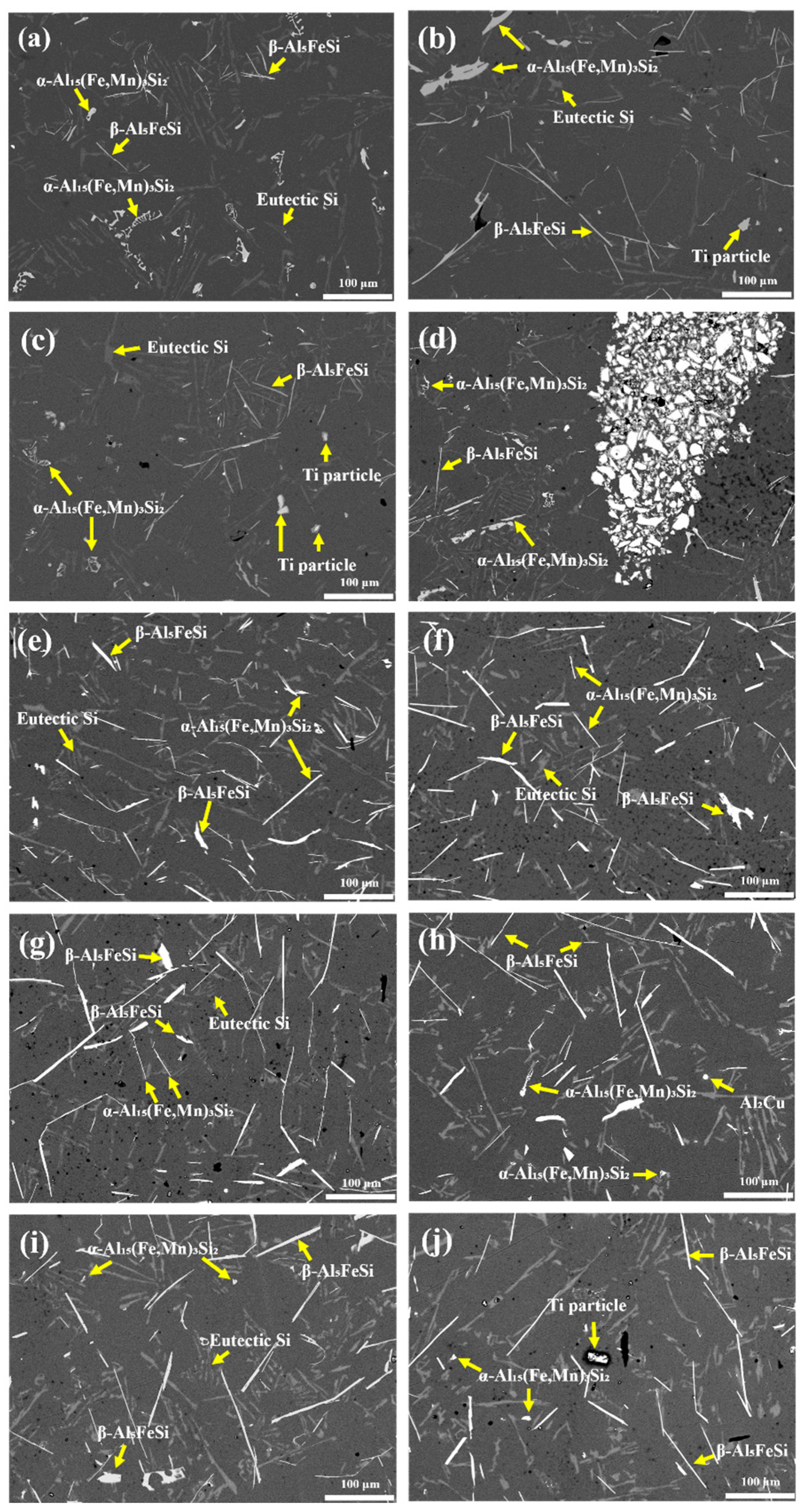
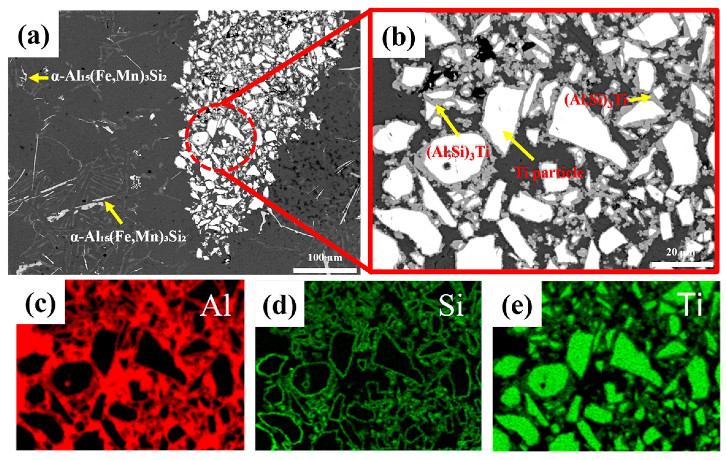
Figure 2 presents low-magnification SEM images of specimens fabricated with different types and contents of foaming agents, while Figure 3 shows high-magnification images and EDS analysis results for the 3 wt.% TiH2 condition.
Fe-based intermetallic compounds, especially β-Al5FeSi, are known to hinder the feeding of liquid metal during solidification, thereby promoting the formation of internal shrinkage pores. In particular, elongated needle-like β-phases can obstruct liquid backfilling between them, leading to increased porosity due to formation of shrinkage cavities [32]. To correlate this pore formation mechanism with the experimental results, the average length and area fraction of α-Al15 (Fe,Mn)3Si2 and β-Al5FeSi under each condition were quantified and are summarized in Table 3.
In the as-cast Al scrap alloy (Figure 2a), a typical microstructure of Al–Si alloys was observed, characterized by eutectic Si, needle-shaped β-Al5FeSi phases, and α-Al15 (Fe,Mn)3Si2 phases in “Chinese script” and “fish bone” morphologies.
With the addition of TiH2 alone (Figure 2b–d), the overall microstructure was similar to that of the as-cast condition. However, localized regions containing Ti particles and (Al,Si)3Ti intermetallic compounds were observed. Especially at 3 wt.% TiH2 (Figure 3b), agglomerated (Al,Si)3Ti phases were clustered around Ti particles, likely resulting from incomplete decomposition of TiH2 or unreacted residual Ti particles. EDS mapping (Figure 3c–e) confirmed that these particles were composed of Al–Si–Ti ternary compounds and metallic Ti. In addition, the β-Al5FeSi phase grew longer overall with an average length of 134.66 ± 8.45 μm under TiH2 addition, and the porosity increased dramatically to 10.06%, especially at 3 wt.%.
In contrast, with the addition of Na2B4O7·10H2O alone (Figure 2e–g), the α-Al15(Fe,Mn)3Si2 phase markedly coarsened compared with the as-cast alloy, transforming from complex Chinese script and fish bone morphologies into elongated plate- or needle-like structures. Meanwhile, β-Al5FeSi phases appeared shorter and thicker, and their area fractions decreased progressively with increasing borax content. The α-phase fraction also slightly decreased. Consequently, at 3 wt.% Na2B4O7·10H2O, the porosity (19.0%) and pore area fraction (0.53%) reached the lowest levels among all conditions. These results indicate that borax suppressed the formation of Fe-rich phases, thereby reducing pore nucleation sites.
In the combined addition conditions (Figure 2h–j), the microstructure reflected the combined influence of both foaming agents. The α-Al15(Fe,Mn)3Si2 phase exhibited significantly suppressed growth, maintaining an average length of ~10 μm and relatively low area fractions across all conditions. In contrast, the β-Al5FeSi phase retained its needle-like morphology similar to the TiH2-only condition, but both its length and area fraction increased under the combined conditions. Notably, at 1.5 wt.% combined addition, the β-phase length (127.14 ± 21.67 μm) and area fraction (2.93 ± 0.99%) were the highest among all conditions. This result is consistent with the increased pore area fraction (2.38%) and porosity (27.0%) observed at the same condition. Therefore, the synergistic effect identified in this study is not limited to hydrogen release from TiH2 decomposition but is also closely related to the β-phase evolution induced by borax addition and its influence on pore formation.

3.3. SDAS

Figure 4 presents the variation in secondary dendrite arm spacing (SDAS) as a function of foaming agent type and content.
With the addition of TiH2 alone, SDAS exhibited a clear decreasing trend, from 48.76 ± 8.1 µm at 1 wt.% to 33.86 ± 7.0 µm at 3 wt.%. This trend suggests that Ti acted as a heterogeneous nucleation site during solidification, thereby promoting grain refinement. According to prior studies, TiAl3 phases can form around 665 °C when the Ti content reaches approximately 0.15 wt.%, serving as effective heterogeneous nucleation sites via encapsulation reactions [33]. Compared to homogeneous nucleation, heterogeneous nucleation requires lower activation energy and fewer atoms, leading to more efficient grain formation and reduction of SDAS. Although TiAl3 phases were not directly observed in this study, the (Al,Si)3Ti phases identified in Figure 3b are presumed to have played a similar role.
In contrast, with the addition of Na2B4O7·10H2O alone, SDAS decreased to 47.78 ± 3.9 µm at 1.5 wt.%, but increased sharply to 60.16 ± 7.9 µm at 3 wt.%. SEM analysis (Figure 2e–g) showed that Fe-based intermetallics such as α-Al15(Fe,Mn)3Si2 and β-Al5FeSi transformed into relatively simple acicular morphologies. This change is likely due to the reaction between B and Fe, which may have influenced phase formation and precipitation behavior [34].
With the combined addition of TiH2 and Na2B4O7·10H2O, SDAS decreased from 49.66 ± 3.9 µm to 42.86 ± 7.0 µm. As shown in Table 2 and Figure 2h–j, the α-Al15(Fe,Mn)3Si2 phase appeared significantly refined compared to the Na2B4O7·10H2O alone condition, while the β-phase retained its acicular shape. Some residual Ti particles were also observed. These combined microstructural features likely contributed to the refinement of SDAS.

3.4. Vickers Hardness

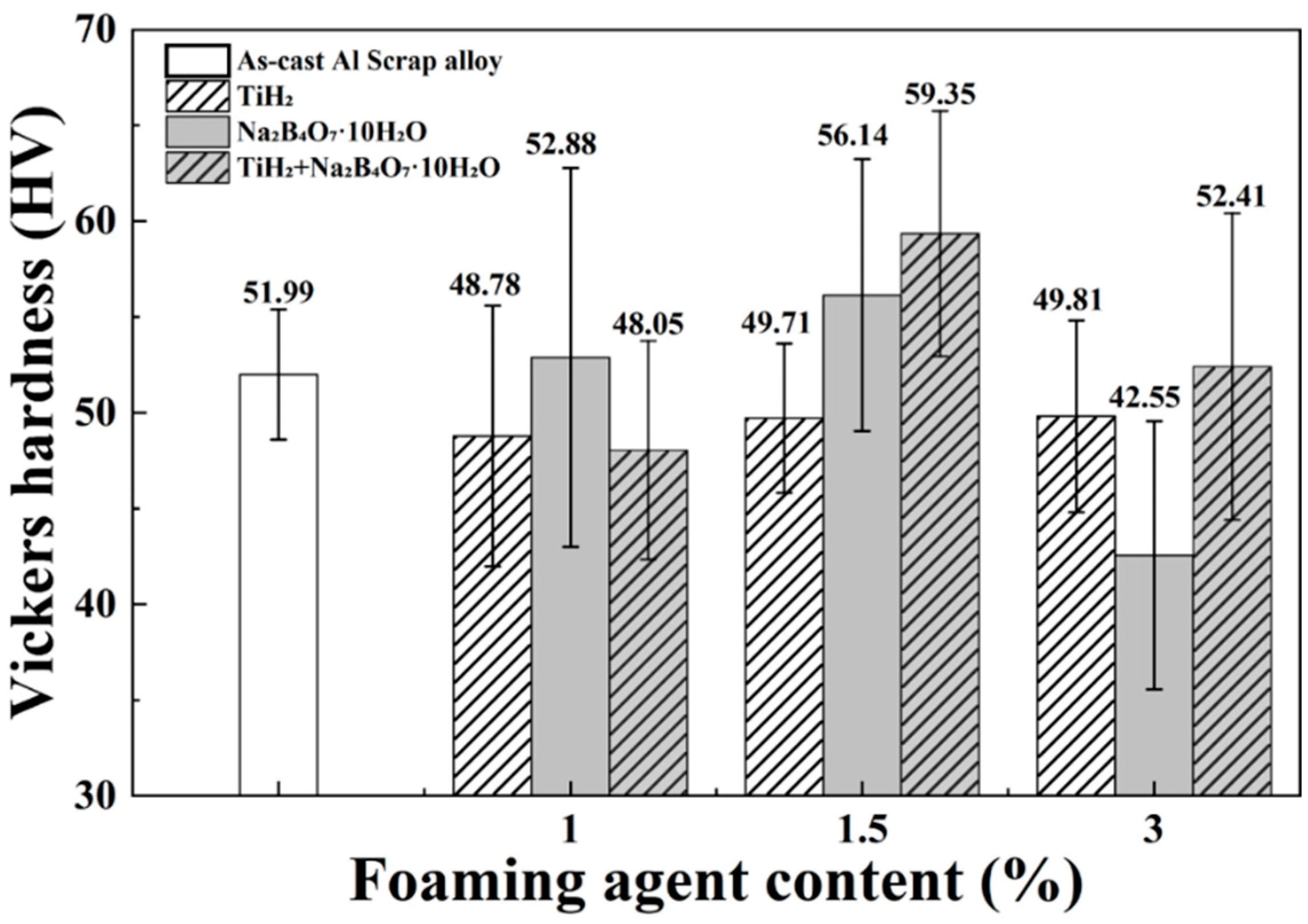
Figure 5 illustrates the variation in Vickers hardness of the alloys according to the foaming agent conditions.
With the addition of TiH2 alone, the hardness remained nearly constant, from 48.78 ± 6.8 HV to 49.81 ± 5.0 HV, despite an increase in porosity. This indicates that the effects of grain refinement and solid solution strengthening by Ti compensated for the mechanical weakening caused by increased porosity. During solidification, Ti forms intermetallic compounds such as Al3Ti and (Al,Si)3Ti, which act as heterogeneous nucleation sites and promote grain refinement. These phases hinder dislocation motion, thereby contributing to strengthening based on the Hall–Petch relationship. In addition, some Ti atoms may dissolve into the Al matrix, causing lattice distortion and further obstructing dislocation movement, which suggests the possibility of solid solution strengthening. Similar strengthening mechanisms resulting from Ti addition have also been reported in previous studies on Al alloys [35,36]. Moreover, despite the increase in the length of β-Al5FeSi phase to 142.35 ± 19.83 µm with TiH2 addition, no deterioration in overall hardness was observed, implying that the influence of the β-phase on mechanical properties may be relatively limited.
With the addition of Na2B4O7·10H2O alone, the hardness values were relatively higher than those of the addition of TiH2 alone alloys, recording 52.88 ± 9.9 HV and 56.14 ± 7.1 HV at 1 wt.% and 1.5 wt.%, respectively. In particular, the 1.5 wt.% condition showed a reduced SDAS of 47.78 ± 3.9 µm, indicating a partial contribution from grain refinement. However, at 3 wt.%, SDAS increased to 60.16 ± 7.9 µm, and the hardness dropped to 42.55 ± 7.0 HV. Under this condition, the average length of α-Al15(Fe,Mn)3Si2 was observed to be 110.53 ± 14.91 µm, suggesting that the presence of coarse acicular intermetallics may have led to stress concentration and deterioration of mechanical properties.
In the case of the combined addition of the two foaming agents, the hardness was relatively low at 48.05 ± 5.7 HV for 1 wt.%, but increased significantly to 59.35 ± 6.4 HV at 1.5 wt.%, the highest among all conditions. This improvement is attributed to the synergistic effect of grain refinement by TiH2 and the morphological and distributional changes of intermetallic compounds induced by Na2B4O7·10H2O. In particular, in this condition, α-Al15(Fe,Mn)3Si2 appeared shorter and more simplified in morphology compared to other cases, which likely mitigated stress concentration and contributed positively to hardness. These findings suggest that the mechanical properties can be optimized in compositions where the strengthening mechanisms of both foaming agents are effectively combined.

3.5. Electrochemical Measurement

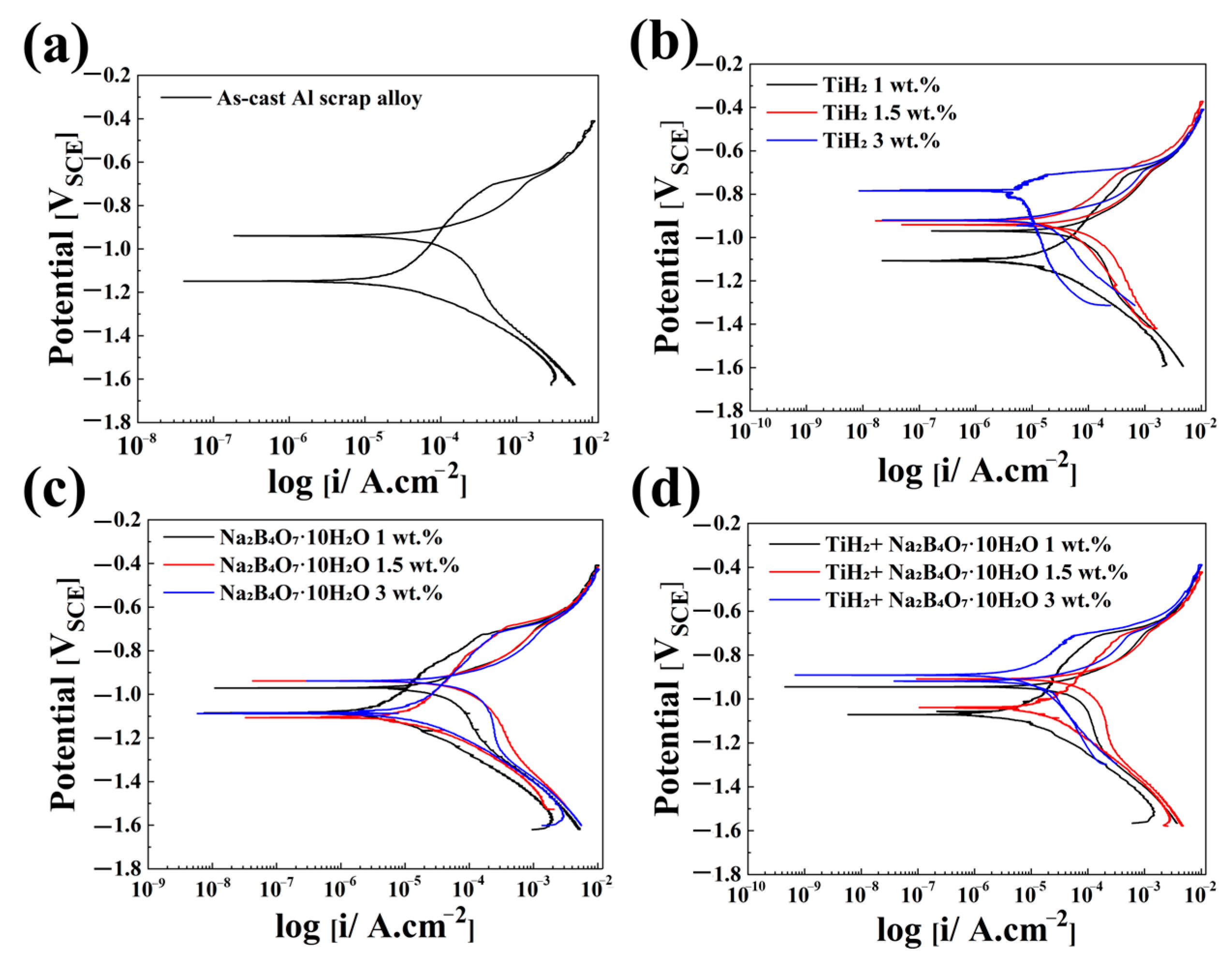
Cyclic Potentiodynamic Polarization (CPDP) is a representative electrochemical technique for quantitatively evaluating the corrosion behavior of metallic surfaces. In this study, CPDP tests were conducted in a 3.5 wt.% NaCl aqueous solution, and the results are presented in Table 4 and Figure 6. This method is suitable for assessing the early-stage corrosion behavior and electrochemical reactivity of alloys over a short duration. The corrosion resistance was compared based on corrosion potential (E_corr), corrosion current density (I_corr), and pitting potential (E_pit), according to the type and content of the foaming agents added to the alloys.
The as-cast alloy exhibited the most negative E_corr (−1.149 V) and the highest I_corr (14.740 μA/cm2), indicating poor overall corrosion resistance. This suggests that the relatively unstable oxide layer on pure aluminum allows facile electron and ion exchange at the metal–electrolyte interface, thereby accelerating metal oxidation. However, its relatively positive E_pit (−0.704 V), the highest among all conditions, implies relatively better resistance to localized corrosion (e.g., pitting). This may reflect the limited number of active corrosion sites due to the spontaneous formation of a passivating film.
With the addition of TiH2 alone, E_corr shifted significantly in the noble (positive) direction with increasing TiH2 content, and the lowest I_corr of 1.782 μA/cm2 was observed at 1.5 wt.%. This improvement can be attributed to the formation of a dense and stable oxide layer consisting of TiO2 and Al2O3, formed through the uniform distribution of Al3Ti phases and the solid solution effect of Ti. Such oxide films reduce charge transfer and ion diffusion between the metal surface and the electrolyte, thus minimizing active corrosion sites and suppressing metal oxidation by enhancing electrical insulation [37,38]. In addition, the E_pit remained relatively stable between −0.722 and −0.704 V, indicating enhanced resistance to localized corrosion.
In contrast, With the addition of Na2B4O7·10H2O alone showed relatively similar E_corr values (−1.103 to −1.088 V), but I_corr increased significantly with higher additive content—from 1.102 μA/cm2 at 1 wt.% to 6.410 μA/cm2 at 3 wt.%. Moreover, E_pit shifted negatively from −0.717 V to −0.728 V in a concentration-dependent manner. These results suggest that borax promotes the activation of corrosion by destabilizing the passive film. This may occur due to enhanced chloride ion penetration into the oxide layer, which accelerates film breakdown and metal oxidation. At higher concentrations, borax likely induces structural instability in the film and facilitates the formation of localized electrochemical sites, thereby exacerbating pitting corrosion.
When the two foaming agents were combined, the corrosion potential shifted in the positive direction, the corrosion current density stabilized in the range of 1.970–4.956 μA/cm2, and the pitting potential also showed a relatively stable distribution. These findings suggest a synergistic effect between the oxide film–reinforcing capability of TiH2 and the surface activation behavior of Na2B4O7·10H2O. In essence, the combination of the two foaming agents contributes to enhanced corrosion resistance by suppressing localized corrosion reactions and promoting the self-healing ability of the passive film.

3.6. Weight Loss and Corrosion Rate

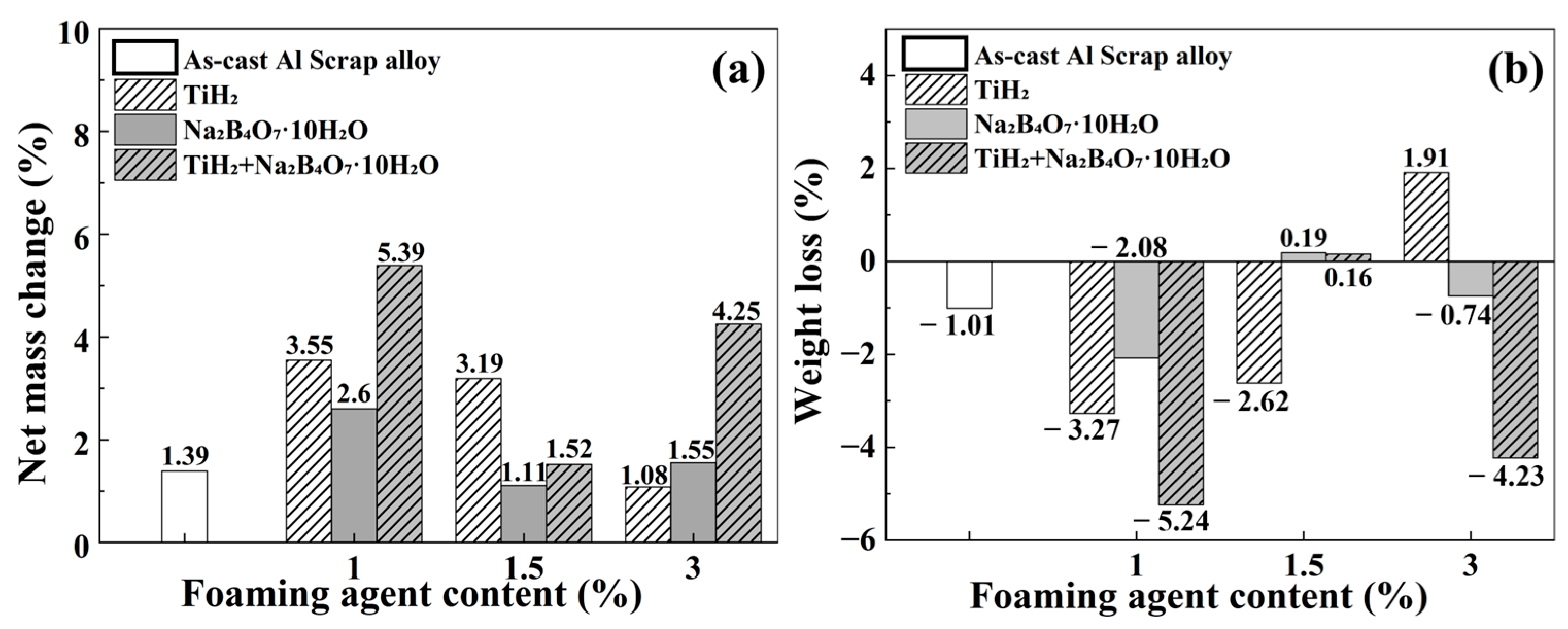
Figure 7 and Table 5 present the results of long-term immersion tests (3.5 wt.% NaCl solution, 720 h) conducted to evaluate the influence of porous structures on the actual corrosion behavior of the alloys. In this study, the values obtained before the removal of corrosion products were expressed as the net mass change rate (%), since the apparent weight increase was attributed to the accumulation of corrosion products rather than actual metal loss. In contrast, the values obtained after removal were reported as the corrosion rate (mpy), which was based on the true mass loss. The corrosion rate was calculated according to ASTM G31 [29] using Equation (4).
C o r r o s i o n   r a t e   ( m p y ) = K W ρ A t
where W is the weight loss (g), A is the exposed surface area (cm2), t is the immersion time (h), and ρ is the density of the specimen (g/cm3).
According to Figure 7a, all specimens exhibited weight gain after immersion prior to the removal of corrosion products. For instance, the TiH2 + Na2B4O7·10H2O 1 wt.% condition showed a weight increase of approximately 5.4%. This indicates that corrosion products accumulated not only on the aluminum matrix surface but also within the internal pores, and that the effect of product accumulation outweighed the actual metal loss. The calculated value was −45.41 mpy, which does not indicate real corrosion protection but rather an apparent effect arising from strongly adhered corrosion products.
In contrast, the TiH2 3 wt.% condition exhibited a slight weight gain before removal, but a subsequent weight loss of about 1.9% was observed after removal, revealing actual metal loss. The corrosion rate after removal was +9.90 mpy, the highest among all conditions presented in Table 5. This high corrosion rate is directly associated with the highest porosity (10.06%) observed under this condition, suggesting that electrolyte penetration into the internal pores promoted localized corrosion. Excessive Ti addition may also have induced over-precipitation of Al3Ti phases, leading to local stress concentrations and an increased number of active corrosion sites.
Similarly, the Na2B4O7·10H2O 1.5 wt.% and TiH2 + Na2B4O7·10H2O 1.5 wt.% conditions shifted to positive values of +1.74 mpy and +1.30 mpy, respectively, after the removal of corrosion products, confirming actual metal loss. Although both specimens initially showed apparent weight gain during immersion, the subsequent mass loss upon product removal indicates hidden metal loss beneath the corrosion layer. These results suggest that the corrosion products formed under these conditions were not sufficiently compact to provide effective protection.

3.7. XRD

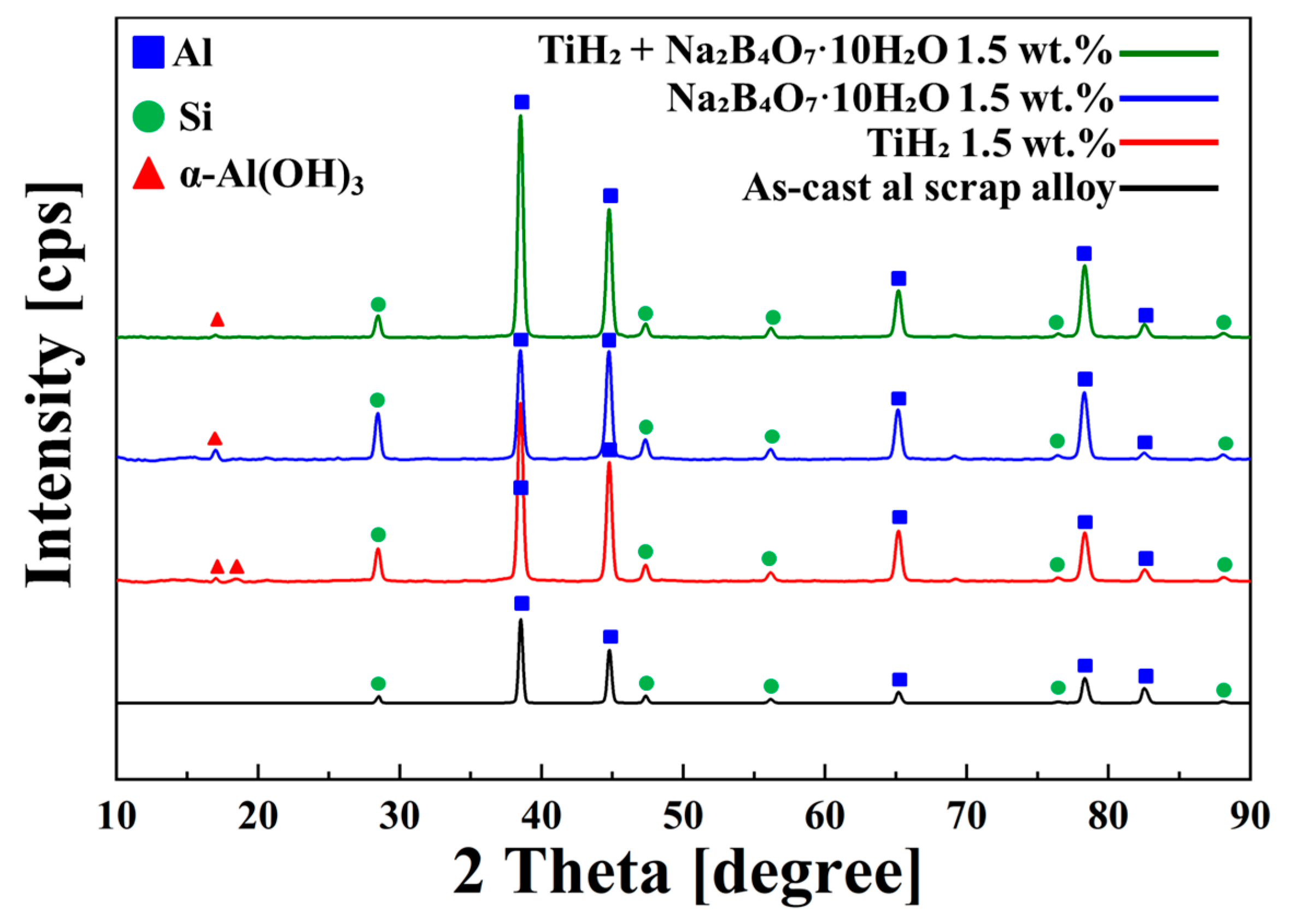
XRD analysis was performed to identify the corrosion products formed on the specimens after 720 h of immersion in 3.5 wt.% NaCl solution, and the results are shown in Figure 8.
The diffraction patterns revealed the presence of major peaks corresponding to Al (2θ ≈ 38.5°, 44.7°, 65.1°, 78.2°, 82°) and Si (28.5°, 47.3°, 56°, 76°, 88°), which were consistently observed on the alloy surfaces. In all foaming agent–added conditions, a distinct peak for α-Al(OH)3 was detected. This phase is a key corrosion product that contributes to the formation of a dense and stable passive film, serving as a barrier to both electron transfer and ion diffusion during electrochemical reactions.
In the as-cast alloy, no distinct diffraction peaks for α-Al(OH)3 were observed; however, a weight increase of approximately 1.4% after immersion indirectly indicates the formation of a small amount of corrosion products.
The enhanced formation of α-Al(OH)3 in the foaming agent–added alloys is attributed to the agents’ influence on the aluminum surface potential and electron density distribution, thereby modulating the redox reaction rates at the metal–electrolyte interface.
TiH2 promotes the formation of Al3Ti, which helps relieve internal stress in the matrix and stabilizes the surface oxide film. Na2B4O7·10H2O, on the other hand, contributes to surface activation and passive film formation, but at high concentrations, it may increase the ionic conductivity of the electrolyte and accelerate corrosion. These microscopic phase transformations form the physical and chemical basis of corrosion resistance, emphasizing that the structural and chemical properties of corrosion products and passive films govern electrochemical corrosion progression.
In summary, the electrochemical measurements, weight change data, and XRD analysis collectively confirm that the type and content of foaming agents critically influence passive film formation and stability, as well as the accumulation behavior of corrosion products—ultimately determining the corrosion resistance of the porous aluminum alloys.

4. Conclusions

In this study, porous aluminum alloys were fabricated using recycled A356 aluminum machining chips as the base material, with TiH2 and Na2B4O7·10H2O employed as foaming agents. The effects of the foaming agents on porosity, microstructure, mechanical properties, and corrosion resistance were comprehensively evaluated. The main conclusions are as follows:    
(1)
With the addition of TiH2 alone, increasing its content led to a higher porosity due to increased hydrogen evolution and induced grain refinement. Moreover, a stable corrosion potential and pitting potential were maintained, resulting in excellent corrosion resistance. However, at 3 wt.%, non-uniform pore distribution and metal loss were observed, indicating a potential degradation in corrosion resistance.
(2)
With the addition of Na2B4O7·10H2O alone, increasing content generally led to reduced corrosion resistance. In particular, the 3 wt.% condition exhibited grain coarsening, a negative shift in pitting potential, and an increase in corrosion current density. In contrast, the 1 and 1.5 wt.% conditions showed relatively stable pore formation and improved hardness, demonstrating positive effects in terms of mechanical performance.
(3)
In the combined addition conditions, an overall balance was achieved across porosity, microstructure, mechanical properties, and corrosion resistance. Particularly, the 1.5 wt.% combined condition exhibited the best overall performance, including high pore area fraction (2.38%), porosity (27.0%), SDAS (48.1 ± 4.8 µm), hardness (59.35 ± 6.4 HV), corrosion potential (−1.039 V), pitting potential (−0.709 V), and corrosion current density (4.956 μA/cm2). The metal loss after corrosion product removal (+1.30 mpy) was also relatively minor.

Author Contributions

Conceptualization, J.B. (Jinwoo Baek), H.L. and E.L.; methodology, J.B. (Jinwoo Baek) and J.B. (Jaehui Bang); software, J.B. (Jinwoo Baek); validation, E.L.; formal analysis, J.B. (Jinwoo Baek); investigation, J.B. (Jinwoo Baek), H.L. and J.B. (Jaehui Bang); resources, J.B. (Jinwoo Baek) and E.L.; data curation, J.B. (Jinwoo Baek), H.L. and J.B. (Jaehui Bang); writing—original draft preparation, J.B. (Jinwoo Baek); writing—review and editing, E.L.; visualization, J.B. (Jinwoo Baek); supervision, E.L.; project administration, E.L.; funding acquisition, E.L. All authors have read and agreed to the published version of the manuscript.

Funding

This research was funded by the Technology Innovation Program (20024924, Development of mold technology with multi-temperature control and surface modification for molding 2.5 mm thick thin material using semi-solid casting method) funded by the Ministry of Trade, Industry & Energy (MOTIE, Korea), and by Korea Basic Science Institute (National research Facilities and Equipment Center) grant funded by Ministry of Education (grant No. 2022R1A6C101B738).

Data Availability Statement

The datasets generated and analyzed during the current study are included in this published article.

Conflicts of Interest

The authors declare that they have no known competing financial interests or personal relationships that could have appeared to influence the work reported in this paper.

References

  1. Yang, Y.; Zhuang, Y.; Wang, H.; Chen, C. Corrosion Test and Corrosion Fatigue Numerical Simulation Research on Marine Structures. Ocean. Eng. 2025, 316, 119931. [Google Scholar] [CrossRef]
  2. Adedipe, O.; Brennan, F.; Kolios, A. Review of Corrosion Fatigue in Offshore Structures: Present Status and Challenges in the Offshore Wind Sector. Renew. Sustain. Energy Rev. 2016, 61, 141–154. [Google Scholar] [CrossRef]
  3. Yang, Y.; Chen, C.; Zhuang, Y.; Suo, Z. Reviewing the Progress of Corrosion Fatigue Research on Marine Structures. Front. Mater. 2024, 11, 1399292. [Google Scholar] [CrossRef]
  4. Thomas, D.J. A Life at Sea and the Corrosion Fatigue Lives of Offshore Structures. J. Fail. Anal. Prev. 2021, 21, 707–710. [Google Scholar] [CrossRef]
  5. Abbas, M.; Shafiee, M. An Overview of Maintenance Management Strategies for Corroded Steel Structures in Extreme Marine Environments. Mar. Struct. 2020, 71, 102718. [Google Scholar] [CrossRef]
  6. Shifler, D.A. Understanding Material Interactions in Marine Environments to Promote Extended Structural Life. Corros. Sci. 2005, 47, 2335–2352. [Google Scholar] [CrossRef]
  7. Yeh, C.L.; Sun, W.E. Use of TiH2 as a Reactant in Combustion Synthesis of Porous Ti5Si3 and Ti5Si3/TiAl Intermetallics. J. Alloys Compd. 2016, 669, 66–71. [Google Scholar] [CrossRef]
  8. Gölbaşı, Z.; Öztürk, B.; Beköz Üllen, N. The Structural and Mechanical Properties of Open-Cell Aluminum Foams: Dependency on Porosity, Pore Size, and Ceramic Particle Addition. J. Alloys Compd. 2024, 1009, 176921. [Google Scholar] [CrossRef]
  9. Parveez, B.; Jamal, N.A.; Maleque, A.; Yusof, F.; Jamadon, N.H.; Adzila, S. Review on Advances in Porous Al Composites and the Possible Way Forward. J. Mater. Res. Technol. 2021, 14, 2017–2038. [Google Scholar] [CrossRef]
  10. Gaur, S.K.; Sahoo, R.R.; Sarkar, J. Performance Optimization of Triple Tube Heat Exchanger Using Aluminum Metal Foam: A Comprehensive Numerical Investigation. Int. Commun. Heat Mass Transf. 2024, 158, 107953. [Google Scholar] [CrossRef]
  11. Antohe, B.V.; Lage, J.L.; Price, D.C.; Weber, R.M. Numerical Characterization of Micro Heat Exchangers Using Experimentally Tested Porous Aluminum Layers. Int. J. Heat Fluid Flow 1996, 17, 594–603. [Google Scholar] [CrossRef]
  12. Barragán De Los Rios, G.A.; Salazar Martínez, S.A.; Mendoza Fandiño, E.; Fernández-Morales, P. Numerical Simulation of Aluminum Foams by Space Holder Infiltration. Int. J. Met. 2024, 18, 3506–3522. [Google Scholar] [CrossRef]
  13. Duarte, I.; Banhart, J. A Study of Aluminium Foam Formation—Kinetics and Microstructure. Acta Mater. 2000, 48, 2349–2362. [Google Scholar] [CrossRef]
  14. Wang, T.; Zuo, X.; Yi, J.; Zhou, Y.; Luo, X.; Guo, S.; Song, W. Enhancing Melt Foam Stability, Form-Filling Process, and Pore Structure Evolution of Shaped Aluminum Foam. J. Mater. Res. Technol. 2024, 33, 5708–5719. [Google Scholar] [CrossRef]
  15. Thulasikanth, V.; Padmanabhan, R. Fabrication of Sustainable Closed-Cell Aluminium Foams Using Recycled Fly Ash and Eggshell Powder. Mater. Today Commun. 2023, 37, 107302. [Google Scholar] [CrossRef]
  16. Brugnolo, F.; Costanza, G.; Tata, M.E. Manufacturing and Characterization of AlSi Foams as Core Materials. Procedia Eng. 2015, 109, 219–227. [Google Scholar] [CrossRef]
  17. Ji, C.; Huang, H.; Wang, T.; Huang, Q. Recent Advances and Future Trends in Processing Methods and Characterization Technologies of Aluminum Foam Composite Structures: A Review. J. Manuf. Process. 2023, 93, 116–152. [Google Scholar] [CrossRef]
  18. Bang, J.; Lee, E. Enhancing Wear Resistance of A390 Aluminum Alloy: A Comprehensive Evaluation of Thermal Sprayed WC, CrC, and Al2O3 Coatings. Coatings 2024, 14, 853. [Google Scholar] [CrossRef]
  19. Han, J.; Dong, G.; Li, S.; Zheng, J.; Wang, J.; Li, H.; Starostenkov, M.D.; Bi, J. Uneven Distribution of Cooling Rate, Microstructure and Mechanical Properties for A356-T6 Wheels Fabricated by Low Pressure Die Casting. J. Manuf. Process. 2024, 127, 196–210. [Google Scholar] [CrossRef]
  20. Liu, Y.; Wang, M.; Cao, Y.; Peng, J.; Yang, D.; Song, D.; Okonkwo, B.O.; Wang, J.; Han, E. Revealing the Effect of Iron Content on the Microstructure Evolution, Mechanical Properties and Corrosion Resistance of the A356-T6 Aluminum Alloys. J. Mater. Res. Technol. 2024, 33, 2263–2274. [Google Scholar] [CrossRef]
  21. Banhart, J. Manufacture, Characterisation and Application of Cellular Metals and Metal Foams. Prog. Mater. Sci. 2001, 46, 559–632. [Google Scholar] [CrossRef]
  22. Sun, B.; Lan, X.; Wang, Z.; Sun, N.; Guo, Z. Grade-Preserving Recycling of Highly Polluted Al-Mg-Si Alloys Scrap: Continuous Filtration under Supergravity-Induced. Sustain. Mater. Technol. 2024, 40, e00918. [Google Scholar] [CrossRef]
  23. Gottmyers Melwyn, J.; Chandragandhi, B.; Sathiyaseelan, G.; Srinath, P. Aluminium Scrap Recycling in a Production Furnace: Minimizing Dross Formation for Sustainable and Efficient Recovery. Mater. Today Proc. 2023. [Google Scholar] [CrossRef]
  24. Korban, P.; Leszczyńska-Madej, B. Effect of Barbotage Refining Time and Recycled Scrap Content on the Microstructure of EN AC 44200 Alloy. Mater. Today Commun. 2023, 37, 107038. [Google Scholar] [CrossRef]
  25. Capuzzi, S.; Timelli, G. Preparation and Melting of Scrap in Aluminum Recycling: A Review. Metals 2018, 8, 249. [Google Scholar] [CrossRef]
  26. Chen, X.; Saada, M.B.; Lavisse, B.; Ammar, A. Recent Advances in the Remelting Process for Recycling Aluminium Alloy Chips: A Critical Review. Int. J. Mater. Form. 2025, 18, 42. [Google Scholar] [CrossRef]
  27. Zhang, Y.; Lei, Y.; Ren, Y.; Ma, W. Removal of Fe Impurities from Al Alloy Scraps by Electromagnetic Directional Solidification Combined with Si Addition. J. Mater. Res. Technol. 2023, 26, 8738–8747. [Google Scholar] [CrossRef]
  28. Wan, B.; Li, W.; Liu, F.; Lu, T.; Jin, S.; Wang, K.; Yi, A.; Tian, J.; Chen, W. Determination of Fluoride Component in the Multifunctional Refining Flux Used for Recycling Aluminum Scrap. J. Mater. Res. Technol. 2020, 9, 3447–3459. [Google Scholar] [CrossRef]
  29. ASTM G31; Standard Guide for Laboratory Immersion Corrosion Testing of Metals. ASTM International: West Conshohocken, PA, USA, 2021.
  30. Samuel, A.M.; Samuel, E.; Songmene, V.; Samuel, F.H. A Review on Porosity Formation in Aluminum-Based Alloys. Materials 2023, 16, 2047. [Google Scholar] [CrossRef]
  31. Gao, J.W.; Shu, D.; Wang, J.; Sun, B.D. Study on Iron Purification from Aluminium Melt by Na2B4O7 Flux. Mater. Sci. Technol. 2009, 25, 619–624. [Google Scholar] [CrossRef]
  32. Kuchariková, L.; Medvecká, D.; Tillová, E.; Belan, J.; Kritikos, M.; Chalupová, M.; Uhríčik, M. The Effect of the β-Al5FeSi Phases on Microstructure, Mechanical and Fatigue Properties in A356.0 Cast Alloys with Higher Fe Content without Additional Alloying of Mn. Materials 2021, 14, 1943. [Google Scholar] [CrossRef]
  33. Liu, G.; Ren, Y.; Ma, W.; Morita, K.; Lei, Y.; Zhan, S.; Lv, G.; Li, S.; Zeng, Y.; Li, R. Development Process and Future Trends of Chemical Refining Agents’ Influence on Grain Refinement in Aluminum Alloys. J. Mater. Res. Technol. 2024, 29, 242–257. [Google Scholar] [CrossRef]
  34. Bang, J.; Byon, E.; Lee, E. Effects of Na2B4O7·10H2O on Microstructure and Mechanical Properties of AlSi7Mg0.3 and AlSi10MnMg Alloys. J. Adv. Mar. Eng. Technol. 2021, 45, 363–370. [Google Scholar] [CrossRef]
  35. Abo Nama, H.A.H.; Esen, İ.; Karakurt, V.; Ahlatci, H. Effect of the Ti Addition on the Corrosion Behavior of Newly Developed AA7075-Ti Alloys. J. Alloys Compd. 2023, 969, 172349. [Google Scholar] [CrossRef]
  36. Wang, T.; Jiang, W.; Wang, X.; Jiang, B.; Wang, Y.; Zhu, D.; Hu, M. Effect of Ti on Microstructure and Mechanical Properties of Al0.8Nb0.5TixV2Zr0.5 Refractory Complex Concentrated Alloys. Int. J. Refract. Met. Hard Mater. 2023, 117, 106383. [Google Scholar] [CrossRef]
  37. Dias, V.; Maciel, H.; Fraga, M.; Lobo, A.O.; Pessoa, R.; Marciano, F.R. Atomic Layer Deposited TiO2 and Al2O3 Thin Films as Coatings for Aluminum Food Packaging Application. Materials 2019, 12, 682. [Google Scholar] [CrossRef] [PubMed]
  38. Staszuk, M.; Pakuła, D.; Reimann, Ł.; Musztyfaga-Staszuk, M.; Socha, R.; Tański, T. Investigation of Ti/Al2O3 + TiO2 and Ti + TiO2/Al2O3 + TiO2 Hybrid Coatings as Protection of Ultra-Light Mg–(Li)–Al–RE Alloys against Corrosion. Sci. Rep. 2022, 12, 19363. [Google Scholar] [CrossRef]
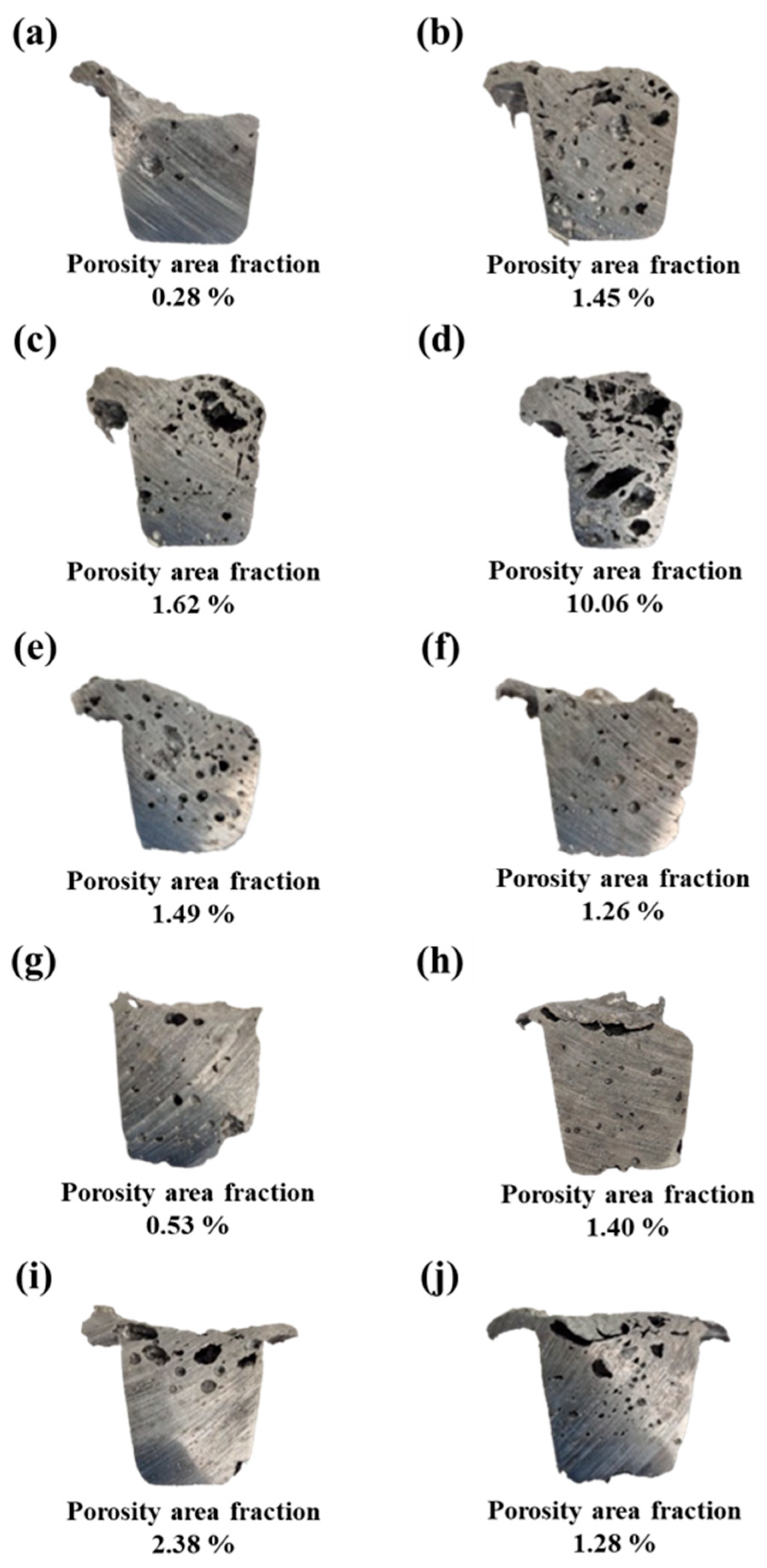
Figure 1. Cross-sectional images of porous aluminum alloy specimens obtained from reduced-pressure tests, showing pore distribution and area fraction analyzed using ImageJ software. Specimens were fabricated with varying types and contents of foaming agents: (a) as-cast Al scrap, (bd) TiH2 at 1, 1.5, and 3 wt.%; (eg) Na2B4O7·10H2O at 1, 1.5, and 3 wt.%; (hj) TiH2 + Na2B4O7·10H2O at 1, 1.5, and 3 wt.%.
Metals 15 01068 g001
Figure 2. SEM images of porous aluminum alloys fabricated with various foaming agents and contents. (a) as-cast Al scrap, (bd) TiH2 at 1, 1.5, and 3 wt.%, (eg) Na2B4O7·10H2O at 1, 1.5, and 3 wt.%, (hj) TiH2 + Na2B4O7·10H2O at 1, 1.5, and 3 wt.%. The yellow arrows indicate the phases formed in each alloy.
Metals 15 01068 g002
Figure 3. (a,b) SEM images of the alloy with 3 wt.% TiH2 addition showing clustered (Al,Si)3Ti phases. (ce) EDS elemental maps of Al, Si, and Ti confirming the composition of Ti-based compounds. The yellow arrows indicate the phases formed in the alloys.
Metals 15 01068 g003
Figure 4. Secondary dendrite arm spacing (SDAS) of as-cast Al scrap alloy and alloys with TiH2, Na2B4O7·10H2O, and their combinations with varying contents (1, 1.5, and 3 wt.%).
Metals 15 01068 g004
Figure 5. Vickers hardness values of as-cast Al scrap alloy and alloys with TiH2, Na2B4O7·10H2O, and their combinations with varying contents (1, 1.5, and 3 wt.%).
Metals 15 01068 g005
Figure 6. Cyclic potentiodynamic polarization (CPDP) curves of (a) As-cast Al scrap alloy, (b) alloy with TiH2 addition, (c) alloy with Na2B4O7·10H2O addition, and (d) alloy with a combined addition of TiH2 and Na2B4O7·10H2O, measured in 3.5 wt.% NaCl solution at room temperature.
Metals 15 01068 g006
Figure 7. (a) Net mass change (%) before removal of corrosion products and (b) weight loss (%) after removal of corrosion products for aluminum alloys with various foaming agent types and contents, after 720 h immersion in 3.5 wt.% NaCl solution.
Metals 15 01068 g007
Figure 8. X-ray diffraction (XRD) patterns of corrosion products formed on the surface of the as-cast Al scrap alloy and alloys with the addition of TiH2, Na2B4O7·10H2O, and their combined addition after immersion in 3.5 wt.% NaCl solution. Only the representative condition of 1.5 wt.% addition was analyzed by XRD to avoid redundancy due to similar phase formation across all compositions.
Metals 15 01068 g008
Table 1. Chemical composition of porous aluminum alloys fabricated with TiH2, Na2B4O7·10H2O, and their combinations (1, 1.5, and 3 wt.%), including an as-cast alloy without foaming agents.
Foaming Agent Type ElementAl (%)Si (%)Mg (%)Fe (%)Ti (%)Cu (%)Mn (%)
Content
As-cast Al ScrapNo foaming
agent added
87.110.071.740.590.080.070.07
TiH21 wt.%88.7410.181.540.720.080.080.06
1.5 wt.%88.148.811.730.770.120.050.07
3 wt.%88.118.521.960.720.140.060.06
Na2B4O7·10H2O1 wt.%88.408.641.421.040.090.060.07
1.5 wt.%86.4110.231.910.870.070.100.07
3 wt.%88.429.451.190.940.050.340.03
TiH2 + Na2B4O7·10H2O1 wt.%86.9110.481.420.750.090.090.05
1.5 wt.%85.8011.860.891.050.090.070.06
3 wt.%88.958.161.001.480.080.030.09
Table 2. Density and porosity of alloys according to foaming agent type and content.
Foaming Agent TypeContentDensity (g/cm3)Porosity (%)
As-cast Al ScrapNo foaming
agent added
2.17019.0
TiH21 wt.%2.02824.3
1.5 wt.%1.96926.5
3 wt.%1.19055.6
Na2B4O7·10H2O1 wt.%1.97326.3
1.5 wt.%2.11021.3
3 wt.%2.17019.0
TiH2 + Na2B4O7·10H2O1 wt.%2.12720.6
1.5 wt.%1.95627.0
3 wt.%2.06223.1
Table 3. Average length and Area fraction of α-Al15(Fe,Mn)3Si2 and β-Al5FeSi intermetallic phases under different types and contents of foaming agents.
Foaming Agent TypeContentIntermetallic Phase Length (μm)Area Fraction of the Fe-Rich Phase (%)
α-Al15(Fe,Mn)3Si2β-Al5FeSiα-Al15(Fe,Mn)3Si2β-Al5FeSi
As-cast Al ScrapNo foaming agent added26.35 ± 2.0130.95 ± 5.371.61 ± 0.240.35 ±0.27
TiH21 wt.%38.03 ± 13.17142.35 ± 19.831.78 ± 0.171.85 ± 0.32
1.5 wt.%22.13 ± 6.71138.73 ± 19.471.67 ± 0.141.63 ± 0.28
3 wt.%36.98 ± 13.17122.89 ± 13.172.50 ± 0.691.29 ± 0.42
Na2B4O7·10H2O1 wt.%97.02 ± 7.3625.27 ± 8.132.16 ± 0.262.07 ± 0.62
1.5 wt.%71.61 ± 7.3422.63 ± 6.711.97 ± 0.181.50 ± 0.30
3 wt.%110.53 ± 14.9131.26 ± 7.441.90 ± 0.011.25 ± 0.26
TiH2 + Na2B4O7·10H2O1 wt.%10.07 ± 1.87107.94 ± 8.790.48 ± 0.441.42 ± 0.16
1.5 wt.%10.54 ± 2.16127.14 ± 21.671.52 ± 0.282.93 ± 0.99
3 wt.%7.37 ± 2.05107.62 ± 9.390.35 ± 0.031.56 ± 0.47
Table 4. Electrochemical parameters of the Cyclic Potentiodynamic Polarization.
Foaming Agent TypeContentCorrosion Potential
(Ecorr, V)
Corrosion Current Density (Icorr, μA/cm2)Pitting Potential
(Epit, V)
As-cast Al ScrapNo foaming
agent added
−1.14914.740 −0.704
TiH21 wt.%−1.1076.201−0.722
1.5 wt.%−0.9221.782−0.704
3 wt.%−0.7842.008−0.708
Na2B4O7·10H2O1 wt.%−1.1031.102−0.717
1.5 wt.%−1.0743.479−0.719
3 wt.%−1.0886.410−0.728
TiH2 + Na2B4O7·10H2O1 wt.%−1.0711.970−0.715
1.5 wt.%−1.0394.956−0.709
3 wt.%−1.0082.748−0.714
Table 5. Corrosion rates (mpy) for the as-cast Al scrap alloy and those with additions of TiH2, Na2B4O7·10H2O, and their combination, calculated after removal of corrosion products following 720 h immersion in 3.5 wt.% NaCl solution. Negative values indicate apparent mass gain due to residual corrosion products or measurement uncertainty, rather than actual corrosion protection.
Foaming Agent TypeContentCorrosion Rate
(mpy)
As-cast Al ScrapNo foaming
agent added
−8.85
TiH21 wt.%−19.04
1.5 wt.%−12.69
3 wt.%+9.90
Na2B4O7·10H2O1 wt.%−15.06
1.5 wt.%+1.74
3 wt.%−5.63
TiH2 + Na2B4O7·10H2O1 wt.%−45.41
1.5 wt.%+1.30
3 wt.%−24.09
Disclaimer/Publisher’s Note: The statements, opinions and data contained in all publications are solely those of the individual author(s) and contributor(s) and not of MDPI and/or the editor(s). MDPI and/or the editor(s) disclaim responsibility for any injury to people or property resulting from any ideas, methods, instructions or products referred to in the content.