Article

Performance of Gears Manufactured Through Additive Manufacturing

by
Animesh Kumar Basak
1,2,*,
Jack Ghasseb
3 and
Alokesh Pramanik
3,*
1
Adelaide Microscopy, The University of Adelaide, Adelaide, SA 5005, Australia
2
Centre for Research Impact & Outcome, Chitkara University, Rajpura 140401, Punjab, India
3
School of Civil and Mechanical Engineering, Curtin University, Bentley, WA 6102, Australia
*
Authors to whom correspondence should be addressed.
Metals 2025, 15(1), 63; https://doi.org/10.3390/met15010063
Submission received: 29 November 2024 / Revised: 18 December 2024 / Accepted: 9 January 2025 / Published: 12 January 2025

Abstract

:
Bound metal deposition (BMD) additive manufacturing technique was used to fabricate gears of PH 17-4 stainless steel material. The gears were fabricated with different layer heights (namely 150 μm and 50 μm) and also subjected to post-fabrication machining. Each gear was tested against commercially available gear in a high-precision control test rig. The operational temperature and noise level were measured during the test, while the material loss due to wear was evaluated at the end of the test. The 50 μm layer height gear performed the best with the least wear loss, minimum noise generation, and temperature rise. The 150 μm layer height gear, which was mechanically polished, performed very similarly to it (50 μm layer height gear) and cost 33% less to print; thus, it was considered the best performing when cost was incorporated. The conclusions found that post machining of printed parts greatly impacts their performance, and thus, the post-print conditions should be considered just as much as the printing conditions.

1. Introduction

Additive manufacturing (3D printing) allows for numerous types of materials to the printed from wide range of feedstock materials ranging from polymers such as acrylonitrile butadiene styrene (ABS) to metal and alloys such as bonded powdered metal (420 stainless steels) [1,2]. Selective laser melting (SLM) uses a high-powered laser to melt the extruded metal powders, which unlike fused filament fabrication (FFF), happens at a much higher temperature [3]. The benefit of this method is that it allows for a wider range of materials to be used because the filament can be made by the user by mixing powdered metal into the wax [4]. The precise nature of 3D printing also allows for many industrial items to be printed and opens up a wide use for 3D printing, such as gears with complex geometries [5,6,7].
The layer thickness during 3D printing considerably affects the part quality and the process. A larger layer thickness will be faster to complete the piece; however, the surface finish will be rougher, while smaller layers provide a better surface finish but take longer to complete [8]. Larger items are thus better to be printed with a higher layer thickness, whilst more precise items or items for industrial use are better to be printed at smaller layer thicknesses. The failure load of printed parts has also decreased with higher layer thicknesses [9,10]. The input parameters of additive manufacturing thus have a considerable impact on the parameters of a piece as well as the post-machining of items depending on their usage. The bound metal deposition additive manufacturing [11], developed by the Desktop Metal Studio [12,13] system, allows for input parameters to be changed. This offers the freedom of analysis by changing different settings for printed items as well as the post-printing sintering conditions.
The selection of printing parameters for 3D printing was found to affect the dynamic performance of components such as polymer spur gears to a high extent [14]. Zhang et al. [14] considered four print parameters in the 3D printing process, such as temperature, printing speed, printing bed temperature, and infill percentage. A total of 100 printed gears were made for a total of 50 matched pairs, with 6 h being the average print time, and were tested against 10 Nm torque load. After the testing of all the gears, each parameter was calculated to find which one was most sensitive to change, with the infill percentage coming out as 45.3%, meaning that infill percentage change had the highest number of discrepancies with the strength of gears, followed by printing speed, then temperature, with the least sensitive at 8.6% being bed temperature. It is expected that a lower infill will reduce the internal strength of a print as opposed to being a fully dense object [8]. In addition, it was found that the wear performance of 3D-printed gears increased by three times after the optimized parameter setting was applied during their manufacturing [14].
Another investigation found that to manufacture good quality in a printed part, influential factors that must be considered are material properties, machine specifications, printing conditions, and process parameters [8,15]. Tran et al. [16] investigated the dimensional accuracy of polylactic acid (PLA) gear printed by fused deposition modeling (FDM) using a nozzle diameter of 0.3 mm, a layer thickness of 0.2 mm, a printing speed of 15–20 mm/s, a filament diameter of 1.8 mm, a rectilinear path cycle, and a printing temperature of 205 °C for PLA and 230 °C for acrylonitrile butadiene styrene (ABS). The gears were printed successfully and dimensionally accurate in all prints. Dimić et al. [17] investigated the influence of material type on the operational characteristics of spur gears (module 4 and standard pressure angle 20 °C) manufactured by the FDM using ABS and PLA. The infill percentage of the prints was 95%, and the layer height was 300 μm. The unlubricated gears were tested back-to-back, and the torque load on the gears was held at a constant at 20 Nm; however, the number of revolutions per minute varied from 0 to 1400 rpm at increments of 200. Each increment was held for 10 min; thus, the total rotation was finished after 60 min. The gears fractured at different times; at 30 min at 600 rpm, the ABS plastic fractured and teeth broke, while PLA endured for longer and fractured at 90 min at 1400 rpm. The ABS gear temperature peaked at around 120 °C and slowly reduced until fracture, while PLA stayed at a constant temperature of around 80 °C until 40 min, when it started declining to about 50 °C. It was found that there was almost no vibration for both under 200 rpm, but the vibration significantly increased with the increase in speed from 300 to 400 rpm, reaching a peak of around 500 rpm and then declining with a further increase in speed. Chemezov et al. [18] investigated the surface quality of 3D-printed (FFF) PLA gears by varying print speed and layer height. Gears with 17 teeth and the 2.3 module were manufactured at (a) 200 μm layer height, 60 mm/s print speed, platform raft adhesion, 50 mm/s infill speed and (b) 100 μm layer height, 30 mm/s print speed, and 25 mm/s infill speed, where other parameters were constant. The gears printed using the second set of conditions gave flatter, denser, and smoother surfaces without the residue of plastic. Dennig et al. [19] tested gears of PLA, ABS, polyamide (PA), and PA carbon fiber (CF) composite printed by FFF. The failure of the gears occurred due to melting, tooth rot failure, deformation, delamination, pitting, high wear, and tooth fracture. The gears operated at around 100 °C and continued to go up during operation, which made the outer part of the PLA gear melt and fail before the end of the operation. The ABS gear suffered broken teeth; however, while the PLA gear failed at tooth rot, the ABS gear went to loads of about 16 MPa. Both the PA and PA-CF had tooth rot after an operation of 2,000,000 cycles, while the PA-CF began to plastically deform. It was reported that the printing process and the accuracy of the geometry did not affect the failure mode. The most important parameter was the friction coefficient of the different materials [20]. Due to friction, the tooth root will heat up and affect the material properties. Karmase et al. and others [21,22,23] compared the microsctructure and density of stainless steel gears manufactured from selective laser sinter and conventional methods. The helical gears of 41 teeth and the 1.5 module were made to fit the parameters to be used on a 3 kW 1200 rpm motor. A lower amount of ferrite particles contributes to the higher strength of the 3D-printed gears, where 0.5% porosity was present and unavoidable even when controlling the printing parameters, while the conventional gear had no porosity. Tezel et al. [24] analyzed wear, torque transfer efficiency, and the oil. The 420 steel gears were manufactured again using direct metal laser sintering, and a comparison gear was manufactured using hobbing [25]. The 3D-printed gears had rough surface finish, and one of those two gears were mechanically polished to improve surface quality. The densities of 3D-printed and hobbed gears were 8 and 7.52 g/cm3, respectively. The wear rate of the hobbed gear was less than 20 mg throughout the operation from 200 to 1000 rpm. Additionally, the polished 3D-printed gear also remained constant albeit at a higher wear rate of around 40 mg.
The above analysis clearly showed that there are lots of investigations on the performance of 3D-printed polymer gears. Having said that, there was not much investigation on the performance and cost analysis of 3D-printed metal gears specially manufactured via a bonded metal deposition system. Thus, it is imperatively needed to explore all the manufacturing processes to understand the effectiveness of certain methods and improve the efficiency of manufacturing a specific part. To address this issue, this study investigates the performance and cost of 3D-printed gears using bonded metal deposition systems at different layer heights and post-machining processes. In addition, the performance of 3D-printing was compared with that of traditional gears in terms of temperature, noise level, and wear loss during gear operation. The outcomes of this investigation will be useful for professionals and researchers to understand the gear performance produced by additive manufacturing in general.

2. Materials and Methods

2.1. Feed Stock Materials

The details of the materials were as follows: “17-4 martensitic precipitation hardening stainless steel (17-4 PH SS) powder was formulated into bound metal rods, by mixing metal powder with wax and a polymer binder and acquired commercially. The composition (% wt.) of the metal powder is as follows: 0.07% C, 15.5–17.5% Cr, 3–5% Ni, 3–5% Cu, 1.0% Mn and 0.15–0.45% (Nb + Ta) [8]. 17-4 PH SS is a martensite precipitation hardened stainless steel containing roughly 3 wt. % copper and is immensely strengthened by the precipitation of highly dispersed copper particles in the martensite matrix” [8].

2.2. Additive Manufacturing Process

The details of the additive manufacturing(AM) process were as follows: “AM of the specimens was carried out with the help of the Desktop Metal studio system II, which is based on the material extrusion additive manufacturing (MEAM) technique. The system consists of three modules: printer, debinder and furnace. The system was controlled via Desktop Metal’s software (Fabricate®, Studio System 2, Desktop Metal, Atlanta, GA, USA), also known as Fabricate. Computer aided design (CAD) files of the specimen drawings were imported into the software and oriented on the build plate inside the printer. Following the printing, green parts were composed of both metal powders and binders. Green parts were immersed in a proprietary debind fluid, dissolving primary binder and introduce open pore channels throughout the part in preparation for sintering. Debinding was conducted in two steps:
  • Holding the specimens at 350 °C for the polymer binder to burn out; and
  • slow ramping the temperature up to 450 °C.
The hold duration for the specimens at 350 °C was 1 h, prior to increasing the temperature. Consequently, 30–70% of the primary binder was removed, while the remaining binder retained the specimen shape. All of the specimens were then subjected to sintering (1100–1200 °C), where specimens were heated uniformly below their melting point to remove the secondary binder, causing the metal particles to fuse together.”
During the printing operation, the extrusion rate of 50 mm/min was employed. This was how much of the filament would be extruded onto the workpiece per minute. The extrusion temperature was 130 °C, which was enough to melt the binder/wax and allow it to fuse within the piece. The volumetric build rate was 10 mm3/s with a feedstock force of 100 N. A standard nozzle diameter of 0.5 mm and extruder length of 2 mm were employed. Sintering was performed at 95% H2 and 5% Ar environment. All printed gears were spur gears with a module that would allow for polishing of the teeth to take place, as it would be large enough, and the number of teeth of the printed gears was 30 teeth. The detail CAD of the gear and gear test rig set up was shown in Figure 1 together with optical photographs. The CAD of the printed gears was based on the model and drawing of the commercially sourced input gear (KHK Gears SSG1-30J15) without the setscrew holes, and the bore diameter was 0.5 mm smaller. The additional printing parameters are given in Table 1.
The input gear, which was the control gear, was sourced commercially (KHK Gears SSG1-30J15, RAR, Shefford, UK) with the following characteristics: 45 teeth, around 50–60 HRC with wear-resistant properties. As stated before, the printed metal was 17-4 PH stainless steel with 7.8 g/cm3 [8]. The hardness of the printed parts was about 37 HRC, with a tensile strength of 533 MPa [8]. The details of all gears were given in Table 2. Table 2 also includes the data regarding cost estimation, which is described in Section 3.5.

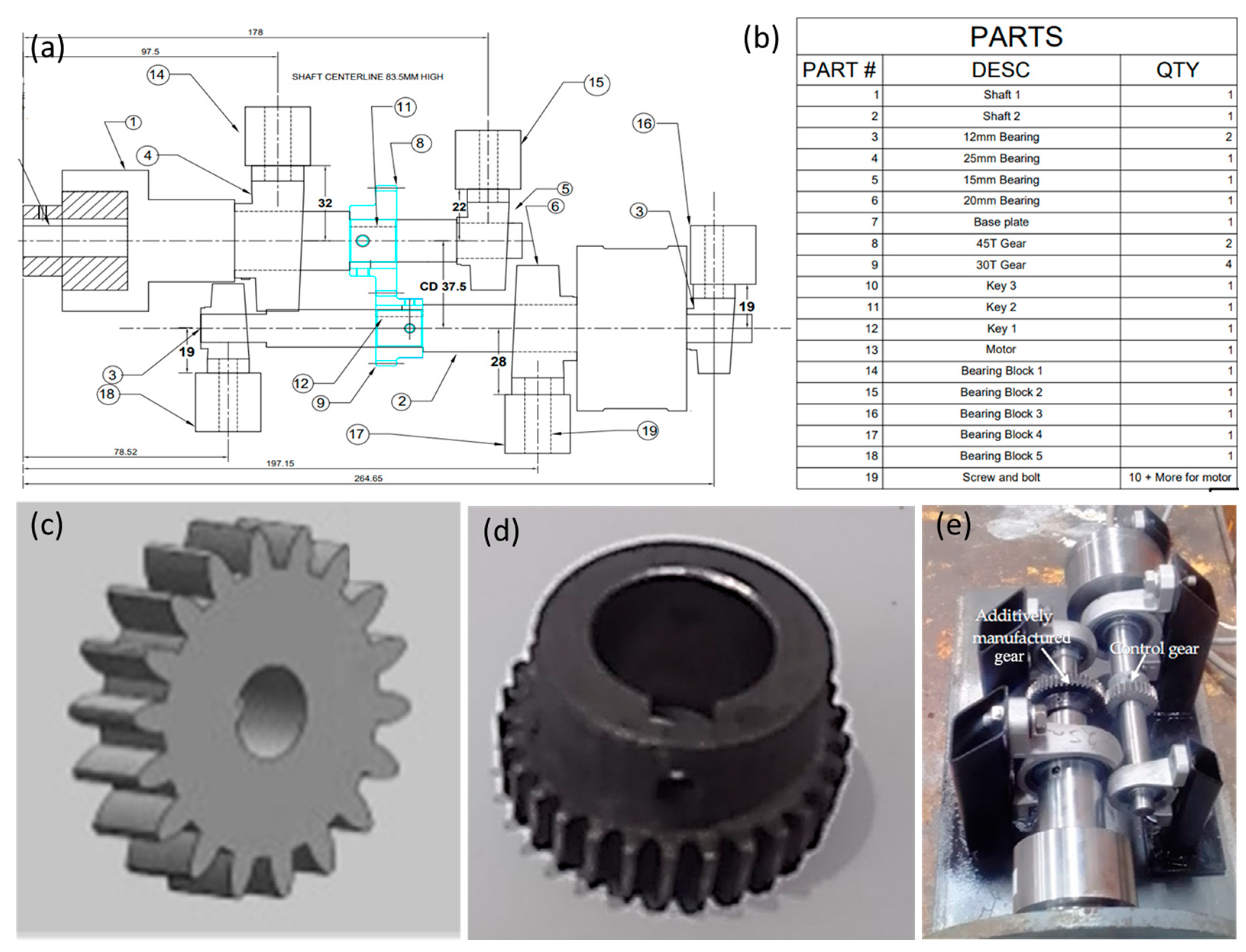
2.3. Experimental Details

The testing of the gear was conducted using an input motor connected to a shaft and the input gear. The gearbox transferred the torque to the output shaft and gear, which was connected to the output load. The rig set-up was shown in Figure 1e. The output load was a dynamo/generator. The input speed of 2100 rpm (max.), with a power max. of 180 watts, generated an input torque of around 1.1 Nm, and so, the power transfer was conducted at low torque and high speed as the input to output speed increased to 1.5 times.
In order to quantify the wear of the material [26,27], the weight of the gears was taken before and after operation using a high precision laboratory scale after thorough cleaning by a high-pressure air gun to ensure the weight taken after was devoid of any remaining debris or grease. In addition, by using the volume of the print, the density of each gear was calculated. Optical microscopy (model: Pro Microscan) was used to investigate the surface morphology before and after the operation. A noise level meter (model: Fluke 945 Sound Meter) was used to measure the level in decibels (Db) of each gear to be tested, and thus, a comparison of the loudness of each gear to be tested can be analyzed. The temperature of each gear during the operation was measured with a digital thermometer (model: Precision RTD Thermometer) (Moore Industries International, Inc., North Hills, CA, USA) at every minute, and the location for each point would be the same for each gear tested.
The gears ran at six speeds, such as 300, 600, 900, 1200, 1500, and 1800 rpm, as confirmed by measuring with a speedometer. Each speed level (cycle 1) lasted for 5 min, at which point the measurements for temperature and noise data were taken every 1 min. A final measurement was taken after each cycle (cycle 1) that would operate at max 2100 rpm (cycle 2) for 10 min. At the end of each cycle, the gears would rest for one hour until the temperature was back to room temperature. The peak temperature and average noise level for cycle 2 and cycle 1 would be compared and given a ratio by dividing cycle 1 by cycle 2. The importance of this ratio showed how much each gear’s performance increased or decreased during cycle 2 after completion of cycle 1. It was expected that the gears would suffer the most wear in cycle 1, and each gear would rotate 105,000 times approximately.

3. Results and Discussion

The density of the printed gears was 98% to that of the theoretically density (7.8 g/cm3) of 17-4 PH SS [8]. This infers the existence of small amount of porosity in the printed structure even after debinding and sintering. Thus, further optimization of the debinding and sintering parameters was foreseen.

3.1. Surface Appearance

A comparison of the morphology of the printed gears before and after the tests was given in Table 3. The protrusions of the layers (150 μm height) in gear 1 were clearly seen before the test (Table 3), which was the general nature of any BMD-produced parts. However, during the test run in the test rig, the outer surface wore out gradually, which was visible. The protrusions in the wear surface were still visible but much smoother with reduced intensity, as it was polished by the control gear. Gear 2 was mechanically polished before testing. After the test run, there was some wear; however, the morphology did not change significantly. The electropolishing did not change the morphology of the gear 3 surface, as the polishing process took place at the micron level. The polishing process also might have removed small protrusions (weakly attached) and generated a stronger surface by reducing pores and micro-openings. Thus, after the test, the surface of gear 3 contained the layer lines more prominently compared to those of gear 1. Protrusions of layers reduced significantly in gear 4, as the layer thickness reduced to 50 μm. The layers appeared to be polished by the control gear, but not as much happened to gear 1 due to high density layers which fortified the surface.
The present observation supported by the findings reported in the literature by Chemezov et al. and others [18,28], who investigated PLA gears fabricated via FFF with 200 μm and 60 μm layer height, which was comparable to gear 1 and gear 2 in the present case. Thus, printing using metal or plastic had no dramatic changes but rather solely the layer height, even when using slightly different printing methods. The layers, however, on all gears are uniform even though the gears go through a process that shrinks the gears 15% during debinding and sintering [8], and no damage seems to have resulted from visual inspection of the gears. As the hardness of the printed gears was 37 HRC [8] and the control gear was 60 HRC [29], it was expected for the control gear to create a polishing effect on the less-hard gears.

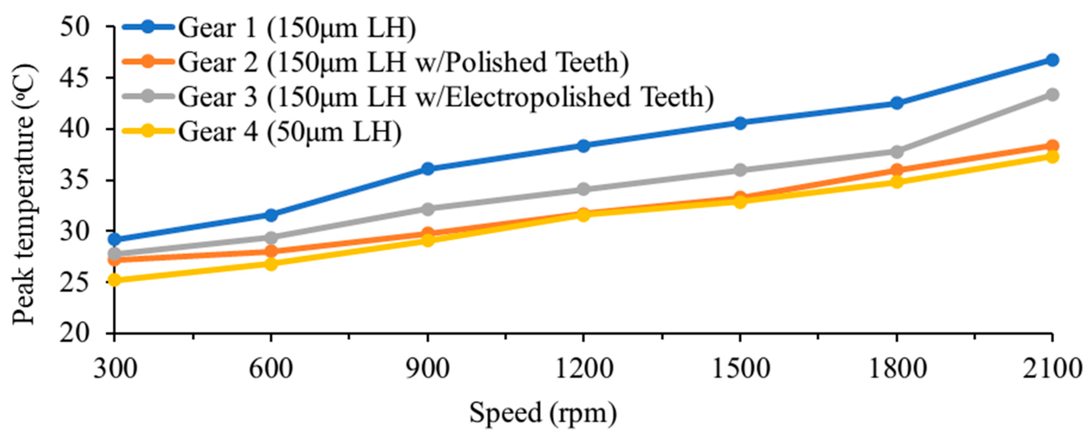
3.2. Temperature Evolution

The peak temperature experienced by the gears operated under different speeds was shown in Figure 2 and Figure 3, respectively, for cycle 1 and 2. The temperature profile of gear 2 and gear 4 was very similar, which indicates that the post-fabrication mechanical grinding (150 μm layer height) produced similar results to that without (50 μm layer height) mechanical grinding. The mechanical polishing of gear 2 took around 20 min to complete by hand. For both cycle 1 and cycle 2, the gradient from 300 rpm to 900 rpm was quite steep at a slope of around 0.03; then, after 900 rpm, the lines level out and only rise at a slope of around 0.008, which means it reduces by about 3.75 times. The gear temperatures for cycle 1 follow roughly the same linear trend; however, the exception was gear 3, which had a steeper climb between 2100 rpm and 1800 rpm. During cycle 2, all gears had reduced temperatures lower than those of cycle 1.
It was found that printed gears (although using ABS rather than steel) using FDM (which was similar to BMD) that ran until failure had a tooth temperature of around 80 °C (during first 30 min of operation). Then, the temperature reduced to 50 °C and became stationary for about 1 h and 10 min [17]. In the present experiments, all the gears had a reduction in temperature after 40 min of operation, and the second cycle resulted in a reduced temperature. Although the ABS gears in the cited experiment were made of plastic rather than metal, there was a clear pattern where the surface (teeth) temperature fell after 30–40 min of operation.
It was found that after 900 rpm, all the gear’s temperature ratios (between cycle1/cycle2) generally stabilized, with minor exceptions, such as 1.08 for gear 1, 1.08 for gear 3, and 1.06 for gear. All these gears (with the exception of gear 2) before 900 rpm start at lower ratios, and with each speed interval, the ratio increases, which shows that the increase in speed increases the discrepancies in cycle 1 and cycle 2. However, this observation did not hold for gear 2, which had a ratio at around 1.06 between 300 and 2100 rpm. This was due to the mechanical polishing of this gear before the test rig run.

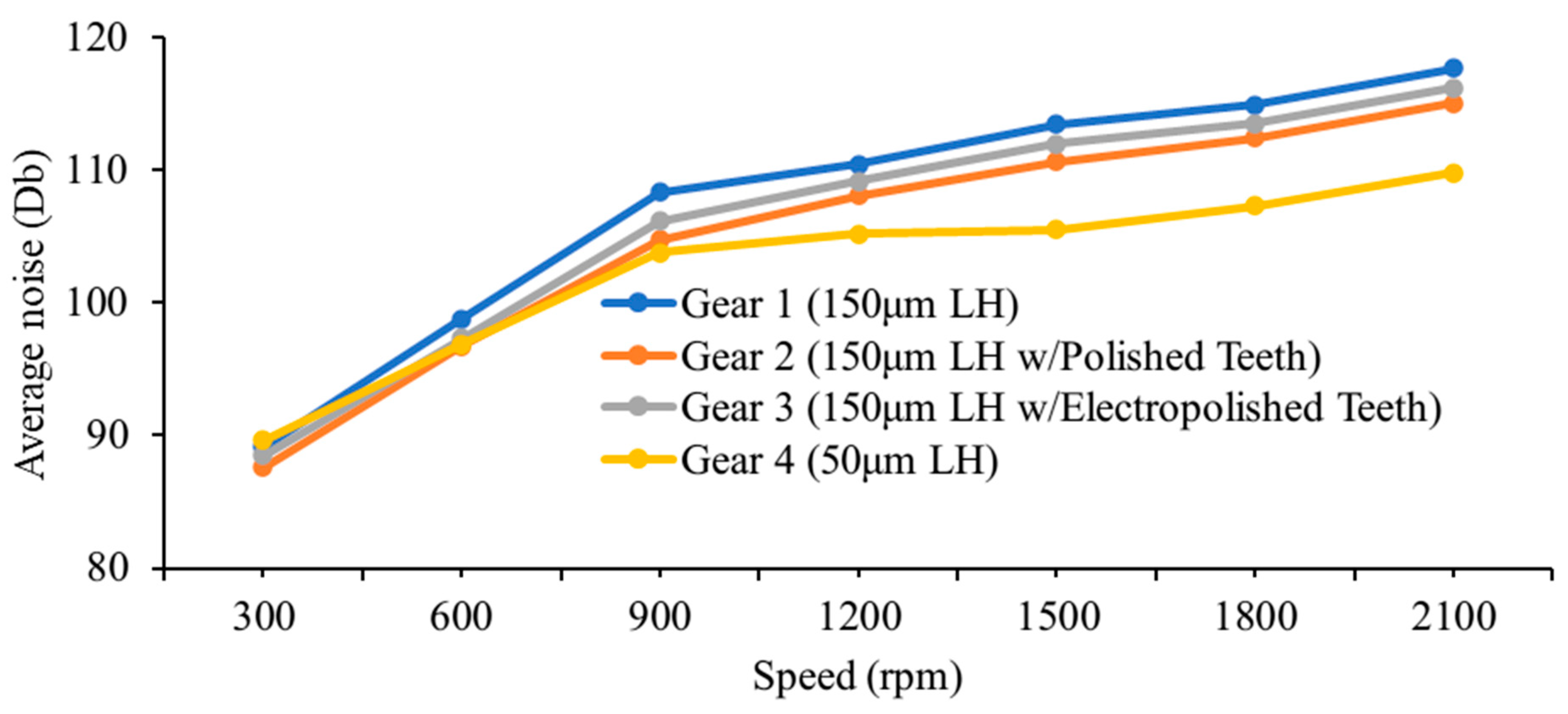
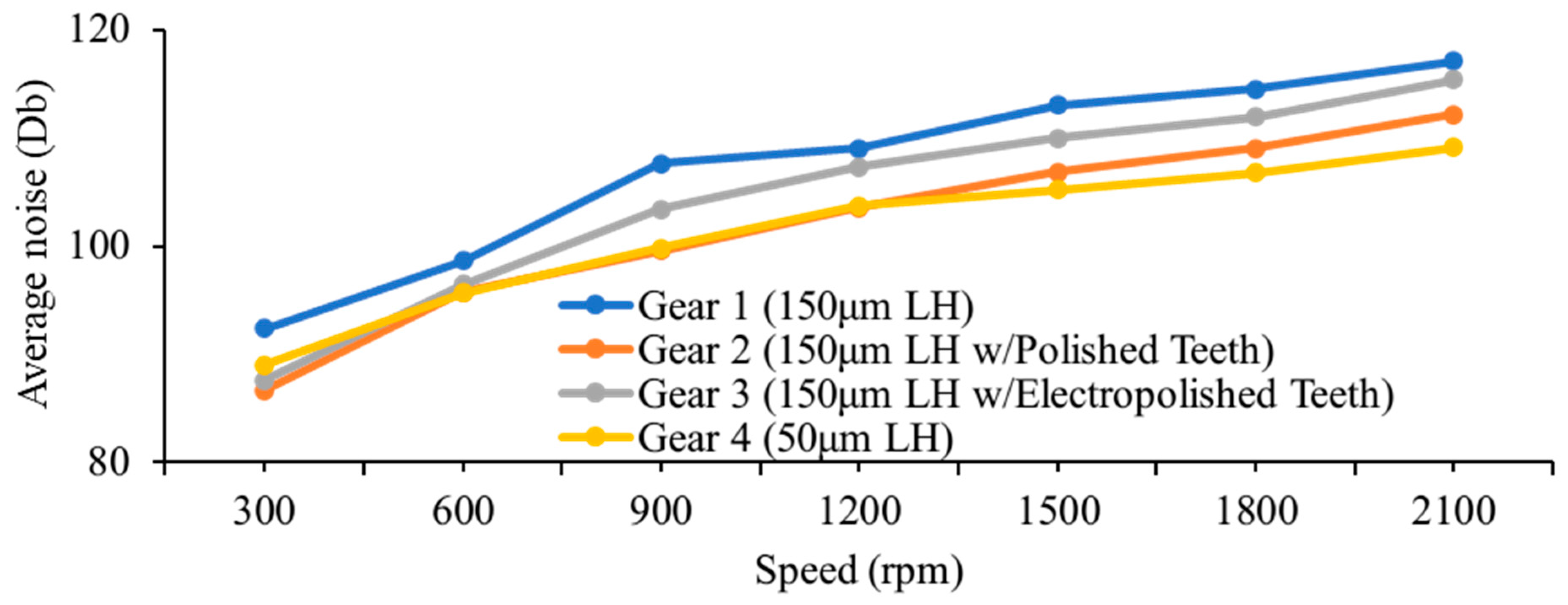
3.3. Noise Generation

The noise level during the test run at different speeds was plotted in Figure 4 and Figure 5, respectively, for cycle 1 and 2. The noise levels followed mostly a similar trend as temperature, with cycle 2 being lower than cycle 1, with a somewhat linear increment with speed. The temperature ratio (between cycle1 and cycle2) of gear 2 was 1.06; however, the noise ratio (between cycle 1 and cycle 2) for gear 2 was around 1.01 for 300 and 600 rpm, then jumped to nearly 1.06 at 900 rpm, then slowly declined to 1.03 at 2100 rpm. The other gears follow their general trend of the temperature ratio for the noise ratio, with ratios stabilizing at 900 rpm after progressively increasing. For all the gears except gear 1, the peak noise ratio was at 900 rpm; thus, 900 rpm seems to be the location where most of the changes take place. Analyzing the noise level of gear 2, the ratio was 1.065 at 900 rpm; after that, it levels out and slowly decreases. This means that the gears printed by the BMD process, irrespective of layer height, perform worse initially and improve after the initial short cycle.
For both temperature evolution and noise generation, for all gears, cycle 1 levels were higher, and at 300 rpm, the ratio was lowest, as this was the slowest speed. During the run in cycle 1, the rough surface on the gear teeth ground, which provides a smoother surface for cycle 2. Thus, torque transfer was more efficient together with lower temperature and noise generation [30]. This was evident in gear 1, which was confined to the roughest surface (without any post-fabrication machining), and explains why the generated temperature and noise were lower at cycle 2.

3.4. Material Loss Due to Wear

A comparison of the material loss of the gears after the test run due to wear was presented in Figure 6. The material loss for gear 1 (83 mg) was nearly double that of gear 2, while the lowest wear occurred for gear 4 (32 mg). This was expected for gear 1, as it had a rougher surface. The wear loss correlates with the surface images (Table 3), in which the gears with observable less wear from the microscope images had also less wear loss. The same trend was also reported in the literature by Tezel et al. [24], where polished gear experienced less wear loss (40 mg) compared to unpolished gear (80 gm).
The control gear only had a loss of 19 mg after operating for approximately 320 min (4 × 2 cycles of 40 min each) or 5.33 h compared to the wear losses of the tested gears, which only operated for 80 min total. Thus, even after operating four times longer, it had the lowest wear loss; however, this was expected, as the hardness of the control gear was about 20 points higher on the HRC scale (Table 1) and had a high level of post-fabrication machining, such as induction hardening on the teeth.

3.5. Cost and Performance

The best-performing gear when accounting for the cost, mechanical performance, and surface morphology was gear 2. Gear 4 was the best-performing gear when not considering cost. Gear 2 performed very similar temperature-wise to gear 4, and it was only slightly louder and had a wear loss of 9 mg more while being 32% less in cost. In addition, as stated above, the electropolishing of gear 3 could have been conducted longer or with higher power; thus, gear 3 may have been the best-performing gear, as the electropolishing was performed conservatively to minimize unintended material loss.
The printed costs of the gears were AUD 62.93 for the 150 μm layer height gear and AUD 92.66 for the 50 μm layer height, with negligible cost for the post-fabrication machining. The commercially sourced gear (SSG1-30J15) cost AUD 142 (adjusted for AUD), and similar gears from other supplies were around the same price (with induced hardened tooth surface). When compared to the best performing and economical gear (e.g., gear 2), it was 2.25 times more expensive. Thus, the alternative might be to produce a 150 μm layer height gear by additive manufacturing, followed by mechanical polishing. It was also 54% more expensive than gear 4, the best-performing gear not considering cost.
Additive manufacturing of gears, especially by FFF/BMD printing, is relatively new, and thus, not much research data are available for one-to-one comparison [31,32,33]. Thus, there is room to fill this knowledge void by exploring different material systems. Layer heights had already been proven to dramatically impact the gear performance, both by this work and others; however, other printing aspects, for example, infill shape, could be conducted to compare the best infill pattern that maximizes gear performance. Further experiments on that can explore more variables, such as making use of a torque meter to measure the torque transfer efficiency of each gear as well as testing the gear total failure for the printed gears and comparing them to a control gear. Further development of 3D printing is foreseen to make the mass production of gears with increased efficiency commercially viable.

4. Conclusions

In this study, the bound metal deposition (BMD) technique was used to manufacture gears from 17-4 PH stainless steel and subjected to a test run against commercially sourced gear in a test rig. This study can be summarized through the following points:
  • The surface modification through mechanical and chemical processes affects the surface wear and wear morphology of gear produced at different conditions.
  • The gear temperatures are linearly proportional to the gear speed. The lower layer thickness generates less temperature in the gears. However, mechanical polishing and chemical polishing reduces the temperature in gears.
  • The trends of noise were like that of temperature, where the noise level was linearly proportional to the gear speed. The lower layer thickness generates less noise in the gears. However, mechanical polishing and chemical polishing reduces the noise level in gears.
  • The minimum wear was noted for the gear with lowest layer height, but the surface modification through polishing reduced the wear.
  • The post-fabrication polishing of the gear increased its overall performance-incorporated cost, surface appearance, and performance, which makes it 33% cheaper compared to others. On the other hand, if only performance was considered, then the lowest layer height (50 μm) gear was the best. Irrespective of the 3D-printed gears, the commercially sourced gear had the lowest wear loss (19 mg), as it possesses higher hardness due to induction heat treatment of its teeth.

Author Contributions

Conceptualization, A.K.B. and A.P.; methodology, J.G. and A.K.B.; validation, A.K.B. and J.G.; formal analysis, J.G.; investigation, J.G.; resources, A.K.B. and A.P.; data curation, A.P.; writing—original draft preparation, J.G.; writing—review and editing, A.K.B. and A.P.; visualization, A.K.B.; supervision, A.P.; project administration, A.P. All authors have read and agreed to the published version of the manuscript.

Funding

This research received no external funding.

Data Availability Statement

The raw/processed data used to produce the results will be made available by the corresponding author upon reasonable request.

Conflicts of Interest

The authors declare that they have no known competing financial interest or personal relationship whatsoever that could have influenced the work reported in this paper.

References

  1. Concli, F.; Bonaiti, L.; Gerosa, R.; Cortese, L.; Nalli, F.; Rosa, F.; Gorla, C. Bending fatigue behavior of 17-4 ph gears produced by additive manufacturing. Appl. Sci. 2021, 11, 3019. [Google Scholar] [CrossRef]
  2. Bulduk, M.E.; Çalışkan, C.İ.; Çoşkun, M.; Özer, G.; Koç, E. Comparison of the effect of different topological designs and process parameters on mechanical strength in gears. Int. J. Adv. Manuf. Technol. 2022, 119, 6707–6716. [Google Scholar] [CrossRef]
  3. Singh, S.; Singh, G.; Prakash, C.; Ramakrishna, S. Current status and future directions of fused filament fabrication. J. Manuf. Process. 2020, 55, 288–306. [Google Scholar] [CrossRef]
  4. Li, X.; Wang, C.; Tian, C.; Fu, S.; Rong, Y.; Wang, L. Digital design and performance evaluation of porous metal-bonded grinding wheels based on minimal surface and 3D printing. Mater. Des. 2021, 203, 109556. [Google Scholar] [CrossRef]
  5. Nugroho, W.T.; Dong, Y.; Pramanik, A. 3D printing composite materials: A comprehensive review. In Composite Materials; Elsevier: Amsterdam, The Netherlands, 2021; pp. 65–115. [Google Scholar]
  6. Hasan, M.R.; Davies, I.J.; Pramanik, A.; John, M.; Biswas, W.K. Technical assessment of 3D-printed spur gears produced from recycled PLA. Int. J. Adv. Manuf. Technol. 2024. [Google Scholar] [CrossRef]
  7. Gupta, K. Recent developments in additive manufacturing of gears: A review. In Advances in Manufacturing Technology XXXII; IOS Press: Amsterdam, The Netherlands, 2018; pp. 131–136. [Google Scholar]
  8. Basak, A.; Lee, A.; Pramanik, A.; Neubauer, K.; Prakash, C.; Shankar, S. Material extrusion additive manufacturing of 17–4 PH stainless steel: Effect of process parameters on mechanical properties. Rapid Prototyp. J. 2023, 29, 1097–1106. [Google Scholar] [CrossRef]
  9. Stojković, J.R.; Turudija, R.; Vitković, N.; Górski, F.; Păcurar, A.; Pleşa, A. An experimental study on the impact of layer height and annealing parameters on the tensile strength and dimensional accuracy of FDM 3D printed parts. Materials 2023, 16, 4574. [Google Scholar] [CrossRef]
  10. Farashi, S.; Vafaee, F. Effect of printing parameters on the tensile strength of FDM 3D samples: A meta-analysis focusing on layer thickness and sample orientation. Prog. Addit. Manuf. 2022, 7, 565–582. [Google Scholar] [CrossRef]
  11. Tontowi, A.E.; Ramdani, L.; Erdizon, R.V.; Baroroh, D.K. Optimization of 3D-printer process parameters for improving quality of polylactic acid printed part. Int. J. Eng. Technol. 2017, 9, 589–600. [Google Scholar]
  12. Dief, A. Desktop Metal Aims to Increase Accessibility of Metal-Making Capabilities [1]; Harvard Business School: Boston, MA, USA, 2022. [Google Scholar]
  13. Watson, A.; Belding, J.; Ellis, B.D. Characterization of 17-4 PH processed via bound metal deposition (BMD). In TMS 2020 149th Annual Meeting & Exhibition Supplemental Proceedings; Springer: Berlin/Heidelberg, Germany, 2020. [Google Scholar]
  14. Zhang, Y.; Mao, K.; Leigh, S.; Shah, A.; Chao, Z.; Ma, G. A parametric study of 3D printed polymer gears. Int. J. Adv. Manuf. Technol. 2020, 107, 4481–4492. [Google Scholar] [CrossRef]
  15. Basak, A.K.; Pramanik, A.; Chen, Y.X.; Prakash, C.; Radhika, N.; Shankar, S. Bound metal deposition of stainless steel 316L: Effect of process variables on microstructural and mechanical behaviors. Materialia 2024, 36, 102196. [Google Scholar] [CrossRef]
  16. Tran, N.H.; Nguyen, V.N.; Ngo, A.V.; Nguyen, V.C. Study on the effect of fused deposition modeling (FDM) process parameters on the printed part quality. Int. J. Eng. Res. Appl. 2017, 7, 71–77. [Google Scholar]
  17. Dimić, A.; Mišković, Ž.; Mitrović, R.; Ristivojević, M.; Stamenić, Z.; Danko, J.; Bucha, J.; Milesich, T. The influence of material on the operational characteristics of spur gears manufactured by the 3D printing technology. Stroj. Čas.-J. Mech. Eng. 2018, 68, 261–270. [Google Scholar] [CrossRef]
  18. Chemezov, D.; Zubatov, D.; Vakhromeev, E.; Shchetnikov, V.; Goremykin, V.; Kuznetsov, A.; Zavrazhnov, D. Surfaces quality of plastic gears made by 3D printing. Theor. Appl. Sci. 2019, 10, 522–529. [Google Scholar] [CrossRef]
  19. Dennig, H.-J.; Zumofen, L.; Kirchheim, A. Feasibility investigation of gears manufactured by fused filament fabrication. In Industrializing Additive Manufacturing, Proceedings of the AMPA2020, Zurich, Switzerland, 1–3 September 2020; Springer: Berlin/Heidelberg, Germany, 2021. [Google Scholar]
  20. Basak, A.K.; Celis, J.P. Coefficient of friction measured from nano-to macro-normal loads on plasma sprayed nanostructured cermet coatings. Metall. Mater. Trans. A 2014, 45, 1049–1056. [Google Scholar] [CrossRef]
  21. Apparao, D.; Raju, M.J. Design and analysis of spur gear manufactured by DMLS process. Mater. Today Proc. 2021, 46, 149–153. [Google Scholar] [CrossRef]
  22. Rokicki, P.; Kozik, B.; Budzik, G.; Dziubek, T.; Bernaczek, J.; Przeszlowski, L.; Markowska, O.; Sobolewski, B.; Rzucidlo, A. Manufacturing of aircraft engine transmission gear with SLS (DMLS) method. Aircr. Eng. Aerosp. Technol. Int. J. 2016, 88, 397–403. [Google Scholar] [CrossRef]
  23. Karmase, P.; Chaudhary, Y. An Experimental Investigation & Analysis of Gear Component Manufactured By 3D Printing & Conventional Process—A Review. Int. Eng. Res. J. 2016, 3, 9. [Google Scholar]
  24. Tezel, T.; Topal, E.S.; Kovan, V. Failure analysis of 3D-printed steel gears. Eng. Fail. Anal. 2020, 110, 104411. [Google Scholar] [CrossRef]
  25. Brecher, C.; Brumm, M.; Krömer, M. Design of gear hobbing processes using simulations and empirical data. Procedia CIRP 2015, 33, 484–489. [Google Scholar] [CrossRef]
  26. Basak, A.K.; Matteazzi, P.; Vardavoulias, M.; Celis, J.P. Corrosion–wear behaviour of thermal sprayed nanostructured FeCu/WC–Co coatings. Wear 2006, 261, 1042–1050. [Google Scholar] [CrossRef]
  27. Basak, A.K.; Celis, J.P.; Vardavoulias, M.; Matteazzi, P. Effect of nanostructuring and Al alloying on friction and wear behaviour of thermal sprayed WC–Co coatings. Surf. Coat. Technol. 2012, 206, 3508–3516. [Google Scholar] [CrossRef]
  28. Buj-Corral, I.; Zayas-Figueras, E.E. Comparative study about dimensional accuracy and form errors of FFF printed spur gears using PLA and Nylon. Polym. Test. 2023, 117, 107862. [Google Scholar] [CrossRef]
  29. Kramer, P.C. Investigation of Rolling-Sliding Contact Fatigue Damage of Carburized Gear Steels. Master’s Thesis, Colorado School of Mines, Golden, CO, USA, 2014. [Google Scholar]
  30. Sachidananda, H.; Raghunandana, K.; Shivamurthy, B. Power loss analysis in altered tooth-sum spur gearing. In MATEC Web of Conferences; EDP Sciences: Les Ulis, France, 2018. [Google Scholar]
  31. Ramadani, R.; Pal, S.; Kegl, M.; Predan, J.; Drstvenšek, I.; Pehan, S.; Belšak, A. Topology optimization and additive manufacturing in producing lightweight and low vibration gear body. Int. J. Adv. Manuf. Technol. 2021, 113, 3389–3399. [Google Scholar] [CrossRef]
  32. Łuszczek, J. Review of methods of designing and additive manufacturing of gears. Biul. Wojsk. Akad. Tech. 2021, 70, 15–34. [Google Scholar]
  33. Brummer, M.; Raddatz, K.J.; Schmitt, M.M.; Schlick, G.; Tobie, T.; Daub, R.; Stahl, K. Static load-carrying behavior and material properties of additively manufactured gears (PBF-LB/M, 16MnCr5). Rapid Prototyp. J. 2023, 29, 117–130. [Google Scholar] [CrossRef]
Figure 1. (a) The CAD of gear test rig set-up (with gear), (b) a description of the parts shown in Figure 1a, (c) the 3D CAD of the gear, and the photo of the (d) gear and (e) gear test rig set-up.
Metals 15 00063 g001
Figure 2. Effect of speed on peak temperature for cycle 1.
Metals 15 00063 g002
Figure 3. Effect of speed on peak temperature for cycle 2.
Metals 15 00063 g003
Figure 4. Effect of speed on average noise level (Db) in cycle 1.
Metals 15 00063 g004
Figure 5. Effect of speed on noise level (Db) in cycle 2.
Metals 15 00063 g005
Figure 6. Material loss due to wear (in milligrams) in gears.
Metals 15 00063 g006
Table 1. BMD printing parameters to fabricate gears.
Layer Height150 μm (gears 1–3), 50 μm (gear 4)
Shell Wall Thickness1.44 mm
Infill Density100%
Print HeadStandard 400 μm (gears 1–3), High resolution 250 μm (gear 4)
Table 2. Characteristics of the BMD printed and control gear.
CharacteristicsGear 1Gear 2Gear 3Gear 4Control Gear
Layer height150 μm150 μm150 μm50 μm-
Post-fabrication conditionsNoneTeeth mechanically grinded followed by polishingTeeth electropolished in phosphoric solutionNoneTooth surface induction hardened (by manufacturer)
Cost (Including debinding and sintering)AUD 62.93AUD 62.93AUD 62.93AUD 92.66AUD 162.00
Printing time3 h 43 m3 h 43 m3 h 43 m11 h 9 m-
Material17-4 PHS45C
Density (g/cm3)7.6447.85
Hardness37 HRC50–60 HRC
Table 3. Surfaces appearance of gear teeth before and after test run.
GearBefore TestAfter Test
Gear 1:
150 μm layer height
Metals 15 00063 i001Metals 15 00063 i002
Gear 2:
150 μm layer height and mechanical polished
Metals 15 00063 i003Metals 15 00063 i004
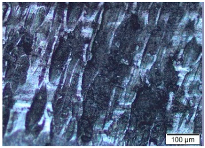
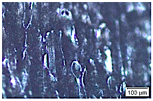
Gear 3:
150 μm layer height and electropolished
Metals 15 00063 i005Metals 15 00063 i006
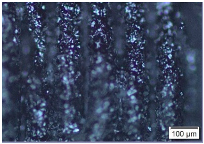
Gear 4:
50 μm layer height
Metals 15 00063 i007Metals 15 00063 i008
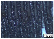
Disclaimer/Publisher’s Note: The statements, opinions and data contained in all publications are solely those of the individual author(s) and contributor(s) and not of MDPI and/or the editor(s). MDPI and/or the editor(s) disclaim responsibility for any injury to people or property resulting from any ideas, methods, instructions or products referred to in the content.

