1. Introduction
In recent decades, recycling has been increasingly used for aluminium production to protect the environment. This production methodology offers substantial benefits including reduced carbon dioxide emissions, significant energy savings, and conservation of the resources. Approximately 10 to 15 times less energy is required for secondary production. As bauxite is only found in a small number of countries in the world, the production of secondary alloys enables other countries to reduce at least part of their dependence on the supply of this resource. Western countries, particularly in the transport sector, have high aluminium recycling rates, exceeding 95%. Notably, a significant portion of recycled aluminium is used in producing Al-Si alloys, predominantly in the automotive industry. The proportion of secondary aluminium alloys is expected to increase [
1,
2].
Many different types of aluminium alloys are used, the chemical composition of which depends on the required properties. Alongside desired alloying elements, aluminium alloys invariably contain impurities, with Fe being the most prevalent in both primary and secondary alloys. It is a major problem, especially in recycled materials, because it is technologically difficult to remove so its content in the alloy gradually increases with repeated recycling cycles. In aluminium casting alloys, it forms intermetallic phases such as Al
3Fe, Al
8Fe
2Si, β-Al
5FeSi, etc. The most detrimental of these are the β—Al
5FeSi phases. These large-sized particles have the shape of thin plates which are visible as needles in the metallographic plane. The Al
5FeSi phases have a weak bond with the matrix and act as stress concentrators. They adversely affect the mechanical properties, causing brittleness, reduced ductility, and castability. The negative effect of the presence of Fe on the fatigue properties of aluminium alloys is widely acknowledged [
3,
4,
5,
6].
The addition of Mn as an alloying element affects the morphology of ferrous phases, thereby reducing the negative impact of Fe. Under the influence of Mn, intermetallic phases in the shape of Chinese script, skeletons, or polyhedrons are formed instead of the harmful brittle plate-like Al
5FeSi phase. This change has a positive effect on both mechanical and fatigue properties. Structural refinement ensues with an optimally chosen Mn content, characterised by a reduction in the Secondary Dendrite Arm Spacing (SDAS). This phenomenon underscores the potential for Mn alloying to enhance the performance of aluminium alloys [
3,
7].
Cu is one of the most important alloying additives in aluminium alloys due to its high solubility and strengthening effect. Many commercial alloys contain Cu either as the main additive or as one of the main alloying elements. The presence of Cu notably enhances strength and hardness in both as-cast and heat-treated conditions by facilitating the formation of Al
2Cu precipitates. Typically, alloys aiming for optimal hardenability are alloyed with 4–6% Cu. To improve hardenability, Cu is often used in combination with Mg. However, Cu generally reduces resistance to general corrosion and, in specific compositions and material conditions, heightens susceptibility to stress corrosion. Cu additions also reduce resistance to hot tearing and reduce castability [
3,
7,
8].
In addition to the chemical composition, other parameters also influence the properties. One of the most important factors is the presence of casting defects. The origin of casting defects can be different. In aluminium alloys, gas-induced pores and shrinkage are most found. Shrinkage cavities are defects that occur because of dimensional shrinkage during solidification, typically occurring in regions with inadequate melt volume. Gas-related defects are pores which are caused by the entrapment of air or gas mixtures within the material [
9,
10]. In conventional casting methods, gas porosity is most often caused by hydrogen. These hydrogen-induced pores are typically small and evenly distributed throughout the casting, arising from the rapid decrease in hydrogen solubility as temperature declines during solidification [
9,
10,
11].
By comparing the mechanical properties of the primary and secondary aluminium alloy AlSi10MnMg(Fe), it was found that the presence of casting defects reduces the ductility of both alloys. The secondary alloy was more susceptible to pore formation due to its increased Fe content. For the samples in which the formation of casting defects was avoided, similar mechanical properties were measured as in the primary alloy [
12].
The cooling rate is an important factor that affects the microstructure and, consequently, the properties of aluminium alloys. It depends on the type of mould, the thickness of the casting, or mould preheating. Rapid heat removal contributes to the formation of a fine-grained microstructure, which causes a significant improvement in mechanical properties, especially ductility, toughness, and hardness, but also corrosion resistance. It was found that the tensile strength of A356 alloy was improved with increasing cooling rate, due to the transformation of the Al5FeSi to Al18Fe2Mg7Si10 phases. The growth and coarsening time of the β-Al5FeSi plate-like phases was also shortened. The maximum UTS of 225.3 MPa was reached by this alloy at a cooling rate of 1.11 °C/s. On the contrary, employing too high cooling rate resulted in degraded mechanical properties due to localised subcooling. At a cooling rate of 1.95 °C/s, a UTS of only 212.59 MPa was achieved [
13,
14]. When casting A356 alloy into preheated moulds at different temperatures, a clear improvement in mechanical properties was found at higher cooling rates. This improvement stemmed from the refinement of α-phase dendrites due to a larger number of nucleation units. At the same time, the morphology of the eutectic Si changed, with Si gaining the form of short rods or rounded grains in the microstructure at higher cooling rates. As the mould preheating temperature increased from 25 °C to 400 °C, the average width of eutectic silicon gradually increased from 3.4 µm to 4 µm. Average length of eutectic Si grew from 9.1 µm to 10.9 µm. The average grain size of α-Al increased from 507 µm to 571 µm [
15].
Excellent corrosion resistance is one of the fundamental features of aluminium alloys, rendering them indispensable in industries such as automotive and aerospace, where resilience against atmospheric corrosion is crucial. Within the pH range of 4.0 to 8.5, aluminium demonstrates passivation, forming a protective layer of Al
2O
3 with a thickness spanning from 1 to 10 nm on its surface. This layer has high stability and prevents direct contact of the material with the environment, thus significantly slowing down corrosion processes. If the Al
2O
3 layer is mechanically or chemically damaged, cathodic and anodic reactions are immediately initiated to restore it. In more aggressive environments, particularly those containing acids, chlorides, or alkalis, dissolution of the passive Al
2O
3 layer can occur, leading to local corrosion. In the case of aluminium casting alloys, attack by pitting corrosion is most common. The pits enlarge over time and can cause damage to the material to a great depth. Failure of the protective layer generally occurs in areas with locally reduced corrosion resistance. These locations are most often various intermetallic phases. The problem is their different potentials. Most intermetallic phases behave cathodically regarding the aluminium matrix, leading to the formation of microgalvanic cells. In terms of corrosion resistance, the most undesirable intermetallic phase is Al
5FeSi, but Cu- and Zn-based phases can also have a negative effect [
16,
17,
18,
19,
20,
21,
22,
23].
Self-hardening aluminium alloys, such as AlZn10Si8Mg, represent a category of aluminium alloys distinguished by their optimal properties without the need for additional heat treatment. These materials age naturally at room temperature. The required precipitation period resulting in suitable mechanical and fatigue properties is 7–10 days. In the automotive industry, self-hardening alloys are gaining in popularity thanks to the possibility of avoiding the heat treatment process. In the automotive industry, they are mainly used to produce cyclically loaded components, displacing AlSi7Mg0.3 and AlSi7Mg0.6 alloys. Compared to these materials, self-hardening AlZn10Si8Mg alloys have higher fatigue resistance due to the more favourable morphology of the individual structural components, particularly the eutectic Si. Thus, they are mainly used in those components where superior fatigue resistance is required. For these reasons, the self-hardening alloy AlZn10Si8Mg emerges as a highly promising alternative [
24,
25,
26,
27].
Currently, two variants of the self-hardening alloy AlZn10Si8Mg are used in the industry. They differ significantly in Fe and Mn content (
Table 1) [
28]. In Unifont alloys, the Cu content is notably limited. The aim of this study is to verify whether it is possible to use an AlZn10Si8Mg alloy with a higher Cu content and to describe its influence on the mechanical properties and corrosion resistance. Unifont 94 alloy with higher Fe content is produced only by high-pressure die casting. Therefore, the aim is to investigate the influence of the casting method on the structure and properties of these higher Fe AlZn10Si8Mg secondary alloys.
2. Materials and Methods
The experimental material was a self-hardening secondary aluminium alloy AlZn10Si8Mg with increased iron content. Due to the high iron content, manganese was introduced into both compared melts to avoid the negative effect of iron. The investigated alloys differ significantly in copper and zinc content. Melt B has a higher percentage of these alloying elements. The complete chemical composition is given in
Table 1.
Alloy A was cast by company UNEKO, Ltd., Zátor, Czech Republic. The alloy was provided in the form of round bars with a diameter of 20 mm and a length of 300 mm. Casting was conducted in sand moulds at temperatures ranging from 700 to 710 °C, followed by refinement using ECOSAL AL 113S salt (KVS EKODIVIZE a.s, Horní Benešov, Czechia) at temperatures ranging from 695 to 705 °C. This alloy naturally precipitates within 7–10 days after casting. Alloy B was cast at the pilot casting plant of the TECNALIA, Irun, Spain. It was made using only recycled aluminium post-consumer scrap supplied by a local recycler. The scrap was melted and slagged in an induction furnace at temperature up to 800 °C. Subsequently, after the aluminium melt was slagged and skimmed, the melt was transferred to an electric resistance furnace and the alloying elements were adjusted to achieve the target composition in
Table 1. The melt was refined with Al-Ti-B and modified with Al-Sr at 620 °C. Finally, the melt was poured into a preheated permanent steel mould at 200 °C.
The castings were sampled with an ATM Brillant 240 (ATM Qness GmbH, Mammelzen, Germany) saw for metallographic and quantitative microstructural analysis. The samples were embedded in dentacryl using a Struers CitoPress-1 embedder (Struers S.A.S., Champigny sur Marne, France). Subsequently, they underwent grinding and polishing using a Struers TegraPol-15 automatic machine, following a dedicated procedure to prepare Al-Si alloys. The different steps of this process vary in duration, sandpaper type, and environment. Before microstructure observation, the samples were etched with 0.5% HF and Dix–Keller.
A NEOPHOT 32 optical microscope (Carl Zeiss, Jena, Germany) was used for metallographic analysis of the individual melts. The microstructure images were taken with a Nikon DS-FI 1 camera (Nikon, Tokyo, Japan) and NIS Elements 5.20 software. The aim of the metallographic analysis was to identify the basic phases present in the structure of each melt. The distribution of these phases and casting defects was also studied. The same equipment was used for quantitative analysis to measure the structural parameters. The SDAS factor (Secondary Dendrite Arm Spacing), the area fraction of eutectic silicon, the size and area fraction of different ferrous phases, and the size and area fraction of casting defects were evaluated. All characteristics were observed at a minimum of 20 sample spots to ensure comprehensive analysis and reliable data collection.
The microstructure was further observed and documented with a TESCAN VEGA LMU II scanning electron microscope (TESCAN VEGA, Kohoutovice, Czech Republic). For this purpose, samples of each melt were prepared by a standard procedure. In addition to etching with 0.5% HF, the samples were deeply etched with concentrated HCl, enabling the 3D morphology of the individual phases to be observed after the alpha phase was etched away.
Brinell hardness tests were performed according to ISO 6506-1 [
30] using CV-3000LDB hardness tester (LFC PTE LTD, Batam, Indonesia). A 5 mm diameter hard-metal ball was pressed for 10 s under a load of 250 kp. The reported hardness values represent the average of five measurements gained from the specimen. All measurements were performed at room temperature. Vickers microhardness was measured according to ISO 6507-1 [
31] with a Zwick/Roell ZHµ microhardness tester (ZwickRoell, Ulm, Germany). A load of 10 g was applied for 10 s, with five indentations made for each phase. The resulting value represents the average of these measurements, ensuring a robust and accurate microhardness evaluation. Two samples of each alloy were used for microstructure observation and hardness measurements.
The tensile strength test was carried out according to ISO 6892-1 [
32] by Instron 5985 (Instron, Norwood, MA, USA). Test bars were made from the castings of the tested melts by chip machining. For each melt, 3 proportional test bars with a diameter of 8 mm and an initial measured length L
o of 40 mm were produced. The fracture surfaces after tensile tests were evaluated using a selective electron microscope.
The corrosion resistance of the tested alloys was evaluated by the Audi test, which is an immersion gravimetric corrosion resistance test known for its efficiency. Three cylindrical samples of each alloy with a diameter of 15 mm and a height of 15 mm were produced by chip machining. They were carefully cleaned with distilled water and ethanol, then dried and weighed with high precision. To prevent contamination, the samples were handled exclusively with gloves or tweezers. The samples were then immersed in a solution of 25.6 mL of 35% HCl, 7.5 g of NaCl and 0.375 l of distilled water. The temperature of the solution during the test was 20 ± 2 °C. After two hours, the samples were again cleaned with distilled water and ethanol, dried, and weighed. Corrosion resistance was determined based on the weight loss of the samples during the test. The resulting weight change represents the average of three samples of a single alloy.
Author Contributions
Conceptualization, M.M., E.T., and J.M.S.; methodology, M.M., E.T., and J.M.S.; software, M.M. and M.C.; validation, E.T. and J.M.S.; formal analysis, Z.Š.; investigation, M.M., E.T., and J.M.S.; resources, M.M. and Z.Š.; data curation, M.M.; writing—original draft preparation, M.M.; writing—review and editing, E.T. and Z.Š.; visualization, M.M.; supervision, E.T. and L.K.; project administration, E.T.; funding acquisition, E.T. and L.K. All authors have read and agreed to the published version of the manuscript.
Funding
The research was funded by following grants: VEGA 1/0461/24 Study of a new generation of secondary (recycled) Al-alloys, I-23-028-04 Effect of manganese on fatigue resistance of secondary AlZn10Si8Mg aluminium alloy, KEGA č. 009ŽU-4/2023 Internationalization of education of foreign students at FME UNIZA in material and technological study programs, and KEGA č. 004ŽU-4/2023 New methods of education and support of soft skills in engineering study at the Faculty of Mechanical Engineering, University of Žilina. Basque Government through the project Elkartek SosIAMet KK-2022/00110.
Data Availability Statement
The data presented in this study are available on request from the corresponding author. The data are not publicly available due to ongoing research into these alloys.
Conflicts of Interest
Author Jon Mikel Sanchez was employed by the company TECNALIA, Basque Research and Technology Alliance (BRTA). The remaining authors declare that the research was conducted in the absence of any commercial or financial relationships that could be construed as a potential conflict of interest.
References
- Padamata, S.K.; Yasinskiy, A.; Polyakov, P. A Review of Secondary Aluminum Production and Its Byproducts. JOM 2021, 73, 2603–2614. [Google Scholar] [CrossRef]
- Wallace, G. Production of secondary aluminium. In Fundamentals of Aluminium Metallurgy, 1st ed.; Lumley, R., Ed.; Woodhead Publishing Limited: Cambridge, UK, 2011; pp. 70–82. [Google Scholar] [CrossRef]
- Panchal, H.; Singh, S.; Sharma, R.; Solanki, K.; Kahar, S. The effect of alloying additions on the structure and properties of Al-Mg-Zn-Si-Mn alloy: A review. Int. J. Sci. Dev. Res. (IJSDR) 2023, 8, 1256–1269. [Google Scholar]
- Arrabal, R.; Mingo, B.; Pardo, A.; Mohedano, M.; Matykina, E.; Merino, M.C.; Rivas, A. Microstructure and corrosion behaviour of A356 aluminium alloy modified with Nd. Mater. Corros. 2015, 66, 535–541. [Google Scholar] [CrossRef]
- Ji, S.; Yang, W.; Gao, F.; Watson, D.; Fan, Z. Effect of iron on the microstructure and mechanical property of Al-Mg-Si-Mn and Al-Mg-Si diecast alloys. Mater. Sci. Eng. A 2013, 564, 130–139. [Google Scholar] [CrossRef]
- Huter, P.; Oberfrank, S.; Grun, F.; Stauder, B. Thermo-mechanical fatigue influence of copper and silicon on hypo-eutectic Al–Si–Cu and Al–Si–Mg cast alloys used in cylinder heads. Int. J. Fatigue. 2016, 88, 142–155. [Google Scholar] [CrossRef]
- Shehadeh, L.M.; Jalham, I.S. The Effect of Adding Different Percentages of Manganese (Mn) and Copper (Cu) on the Mechanical Behavior of Aluminum. Jordan J. Mech. Ind. Eng. 2016, 10, 19–26. [Google Scholar]
- Abdelaziz, M.H.; Samuel, A.M.; Doty, H.W.; Valtierra, S.; Samuel, F.H. Effect of additives on the microstructure and tensile properties of Al–Si alloys. J. Mater. Res. Technol. 2019, 8, 2255–2268. [Google Scholar] [CrossRef]
- Fiorese, E.; Bonollo, F.; Timelli, G.; Arnberg, L.; Gariboldi, E. New classification of defects and imperfections for aluminum alloy castings. Int. J. Met. 2015, 9, 55–66. [Google Scholar] [CrossRef]
- Kucharčík, L.; Bruna, M.; Sládek, A. Influence of Chemical Composition on Porosity in Aluminium Alloys. Arch. Foundry Eng. 2014, 14, 5–8. [Google Scholar] [CrossRef]
- Samuel, A.M.; Samuel, E.; Songmene, V.; Samuel, F.H. A Review on Porosity Formation in Aluminum-Based Alloys. Materials 2023, 16, 2047. [Google Scholar] [CrossRef]
- Niklas, A.; Bakedano, A.; Orden, S.; da Silva, M.; Nogués, E.; Fernandéz-Calvo, A.I. Effect of Microstructure and Casting Defects on the Mechanical Properties of Secondary AlSi10MnMg(Fe) Test Parts Manufactured by Vacuum Assisted high Pressure Die Casting Technology. Mater. Today Proc. 2015, 2, 4931–4938. [Google Scholar] [CrossRef]
- Liu, Z.; Zhou, L.; Li, G. Effects of Cooling Rate on the Microstructure and Tensile Strength of A356 Alloy Wheels. In Proceedings of the 3rd International Conference on Material, Mechanical and Manufacturing Engineering, Guangzhou, China, 27–28 June 2015. [Google Scholar] [CrossRef]
- Muthusamy, G.; Wagstaff, S.; Allanore, A. Effect of Cooling Rate During Solidification of Aluminum–Chromium Alloy. In Light Metals 2020. The Minerals, Metals & Materials Series; Springer: Cham, Switzerland, 2020. [Google Scholar] [CrossRef]
- Alkathafi, M.H.; Khalil, A.A.; Abdalla, A.O. The Effect of Cooling Rate on the Microstructure of A356 Aluminium Alloy. SVOA Mater. Sci. Technol. 2020, 2, 91–100. [Google Scholar]
- Kuchariková, L.; Pastierovičová, L.; Tillová, E.; Uhríčik, M.; Zatkalíková, V.; Šajgalík, M. The Influence of a Corrosive Environment on Fatigue and Mechanical Properties of An Al-Cast Alloy with Higher Fe Content. Metals 2023, 13, 1019. [Google Scholar] [CrossRef]
- Kamarska, K. Investigation of the Corrosion Behaviour of Aluminium Alloy in Selected Environments. Environ. Technol. Resour. Proc. Int. Sci. Pract. Conf. 2019, 3, 92–94. [Google Scholar] [CrossRef]
- Xhanari, K.; Finšgar, M.; Knez Hrnčič, M.; and Maver, U.; and Knez, Ž.; Seiti, B. Green corrosion inhibitors for aluminium and its alloys: A review. RSC Adv. 2017, 7, 27299–27330. [Google Scholar] [CrossRef]
- Svobodová, J.; Luňák, M.; Lattner, M. Analysis of the Increased Iron Content on the Corrosion Resistance of the AlSi7Mg0.3 Alloy Casting. Manuf. Technol. 2019, 19, 1041–1046. [Google Scholar] [CrossRef]
- Hanza, S.; Vrsalovič, L.; Štic, L.; Liveric, L. Corrosion investigations of Al-Si casting alloys in 0.6 M NaCl solution. Eng. Rev. 2020, 41, 115–123. [Google Scholar] [CrossRef]
- Pastierovičová, L.; Kuchariková, L.; Tillová, E.; Chalupová, M.; Liptáková, T.; Švecová, I. Effect of different chloride environments on corrosion behavior of secondary AlSi7Mg0.6 cast alloy with higher Fe content. Mater. Today Proc. 2022, 62, 2450–2456. [Google Scholar] [CrossRef]
- Peng, C.; Liu, Y.; Guo, M.; Gu, T.; Wang, C.; Wang, Z.; Sun, C. Corrosion and pitting behavior of pure aluminum 1060 exposed to Nansha Islands tropical marine atmosphere. Trans. Nonferrous Met. Soc. China. 2022, 32, 448–460. [Google Scholar] [CrossRef]
- Kusmierczak, S.; Hren, I. Influence of AlSi7Mg0.3 Alloy Modification on Corrosion Behaviour in the Salt Environment. Manuf. Technol. 2019, 19, 802–806. [Google Scholar] [CrossRef]
- Kuchariková, L.; Pastierovičová, L.; Tillová, E.; CHalupová, M.; Závodská, D. Investigation of Self-Hardening AlZn10Si8Mg Cast Alloy for the Automotive Industry. Arch. Metall. Mater. 2022, 68, 517–524. [Google Scholar] [CrossRef]
- Rosso, M.; Peter, I.; Castella, C.; Molina, R. Properties of AlZn10Si8Mg Alloys for High Performances Application. Light Metals 2014 2016, 213–218. [Google Scholar] [CrossRef]
- Rosso, M.; Ildiko, P.; Castella, C.; Molina, R. Optimization of Composition for Self-hardening AlZn10Si8Mg Alloys. Mater. Today Proc. 2015, 2, 4949–4956. [Google Scholar] [CrossRef]
- Peter, I.; Rosso, M.; Castella, C.; Molina, R. Self-Hardening Alloys for Automotive Application. Mater. Sci. Forum. 2014, 794–796, 1221–1226. [Google Scholar] [CrossRef]
- Liu, T.; Karkkainen, M.; Natac, L.; Arvikar, V.; Levin, I.; Brever, L.N. Iron-rich intermetallics in high pressure die cast A383 aluminum alloys. Intermetallics 2020, 126, 106814. [Google Scholar] [CrossRef]
- Rheinfelden Alloys. Primary Aluminium Casting Alloys. 2016. Available online: https://rheinfelden-alloys.eu/wp-content/uploads/2017/01/Leporello-Primary-Aluminium-Casting-Alloys_RHEINFELDEN-ALLOYS_2016_EN.pdf (accessed on 19 May 2024).
- ISO 6506-1; Metallic Materials—Brinell Hardness Test. International Organization for Standardization: Geneva, Switzerland, 2014.
- ISO 6507-1; Metallic Materials—Vickers Hardness Test. International Organization for Standardization: Geneva, Switzerland, 2018.
- ISO 6892-1; Metallic Materials—Tensile Testing. International Organization for Standardization: Geneva, Switzerland, 2019.
- Sanchez, J.M.; Arribas, M.; Galarraga, H.; de Cortazar, M.G.; Ellero, M.; Girot, F. Effects of Mn addition, cooling rate and holding temperature on the modification and purification of iron-rich compounds in AlSi10MnMg(Fe) alloy. Heliyon 2023, 9, e13005. [Google Scholar] [CrossRef] [PubMed]
- Fu, Y.; Wang, G.G.; Hu, A.; Li, Y.; Thacker, K.B.; Weiler, J.P.; Hu, H. Formation, charakteristics and control of sludge in Al-containing magnesium alloys: An overview. J. Magnes. Alloys 2022, 10, 599–613. [Google Scholar] [CrossRef]
- Zhang, M.; Liu, S.; Jiang, J.; Wei, W. Effect of Cu content on intergranular corrosion and exfoliation corrosion susceptibility of Al−Zn−Mg−(Cu) alloys. Trans. Nonferrous Met. Soc. China 2023, 33, 1963–1976. [Google Scholar] [CrossRef]
- Kuchariková, L.; Liptáková, T.; Tillová, E.; Kajánek, D.; Schmidová, E. Role of Chemical Composition in Corrosion of Aluminum Alloys. Metals 2018, 8, 581. [Google Scholar] [CrossRef]
- Wang, S.; Meng, G.; Song, M. Effect of Cu Addition on Properties of an Al-La Alloy. Coatings 2023, 13, 1505. [Google Scholar] [CrossRef]
- Scampone, G.; Gursoy, O.; Brutti, S.; Timelli, G. Effect of Zn addition and natural aging on the microstructure and mechanical properties of secondary AlSi7Cu2 alloys. IOP Conf. Ser. Mater. Sci. Eng. 2023, 1274, 012057. [Google Scholar] [CrossRef]
Figure 1.
Microstructure of alloy A, etch. Dix–Keller: (a) α-phase, eutectic, and Al5FeSi needles; (b) α-phase, eutectic, and sludge phases.
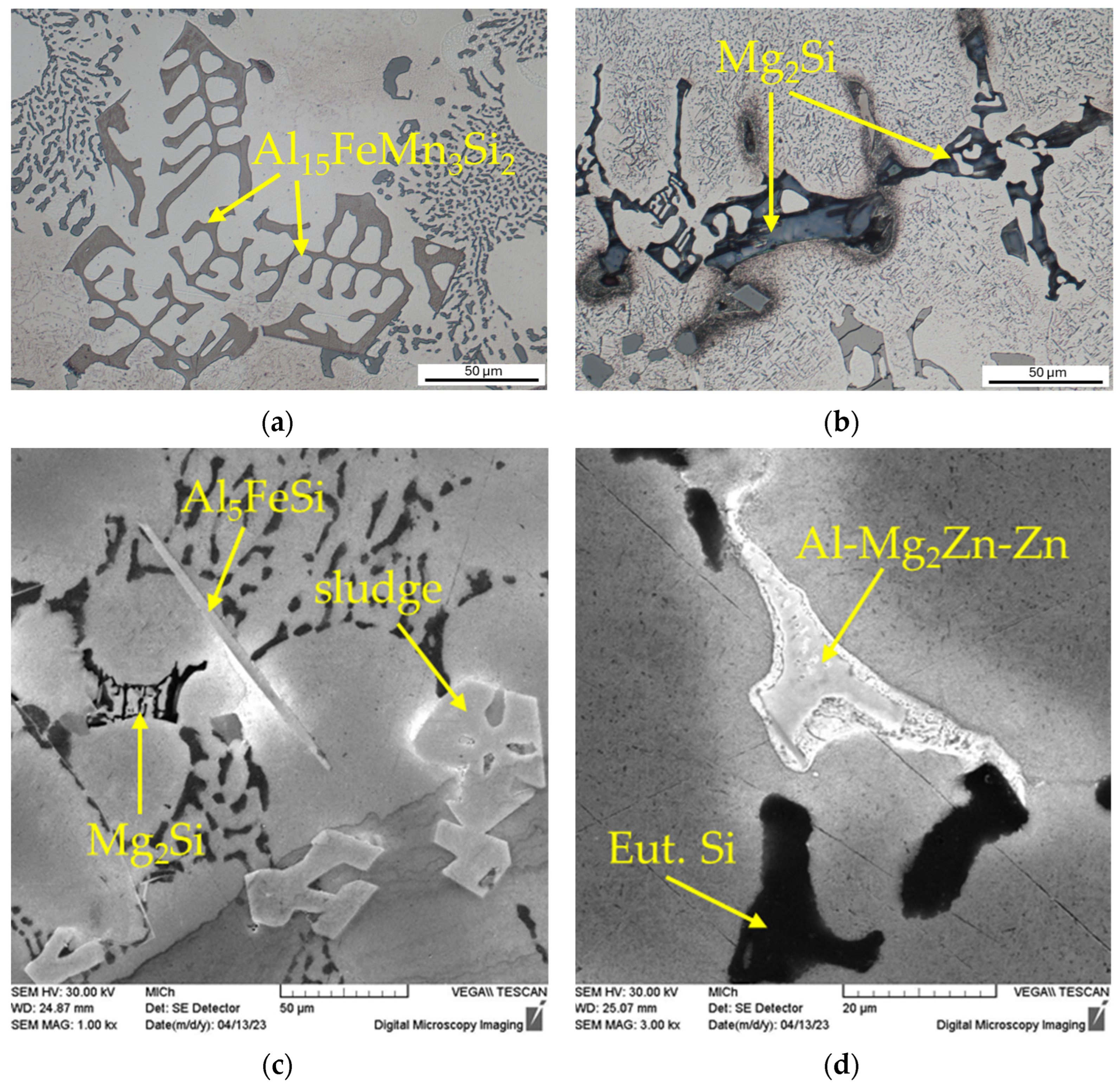
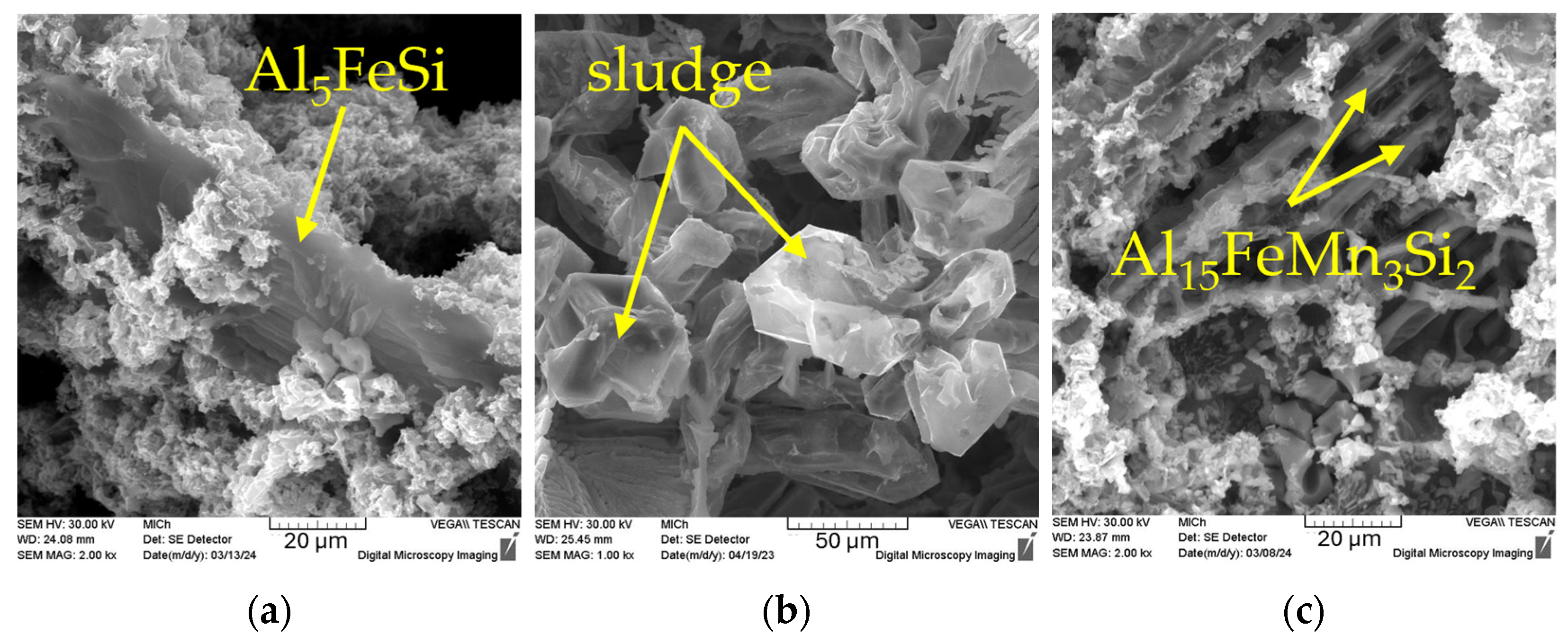
Figure 2.
Details of the microstructure of alloy A: (a) skeleton-like Al15FeMn3Si2 phases (etch. 0.5% HF); (b) skeleton-like Mg2Si phases (etch. Dix–Keller); (c) sludge phases, Al5FeSi needle, skeleton-like Mg2Si phase (etch. 0.5% HF, SEM); (d) ternary eutectic Al-Mg2Zn-Zn (etch. 0.5% HF, SEM).
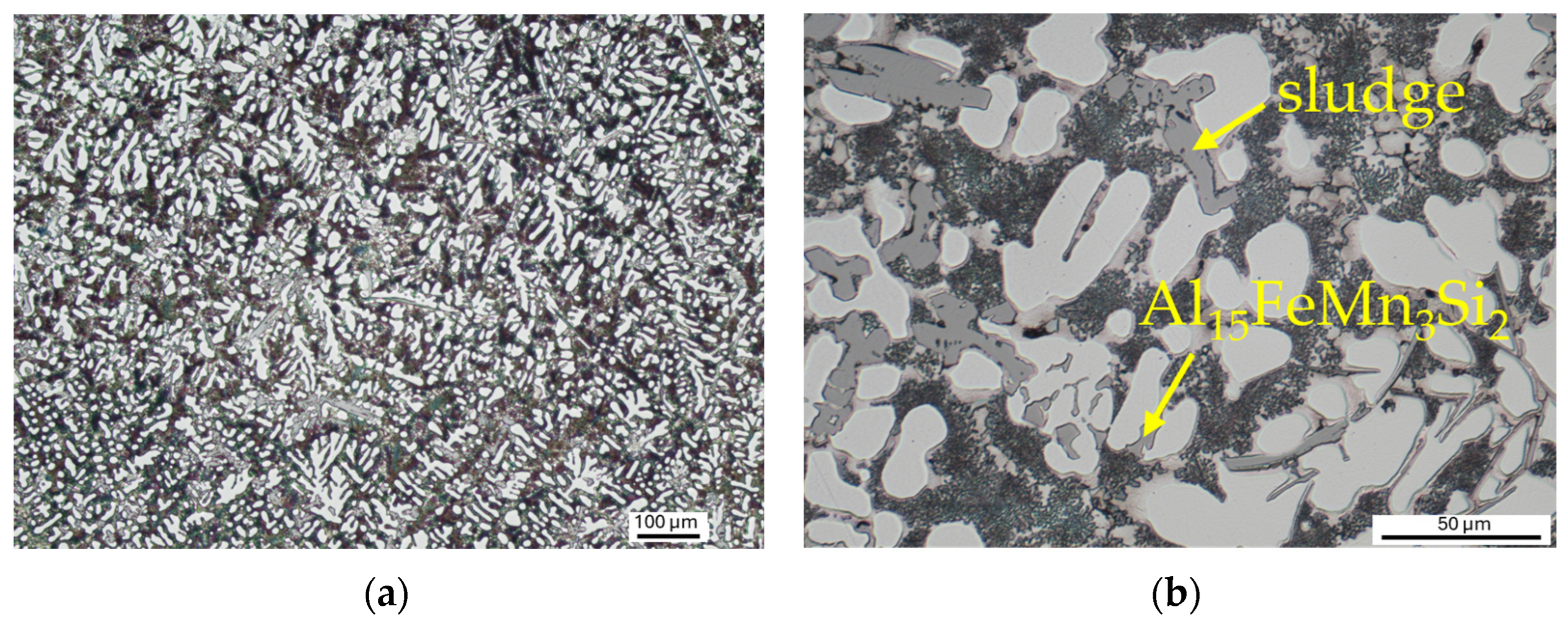
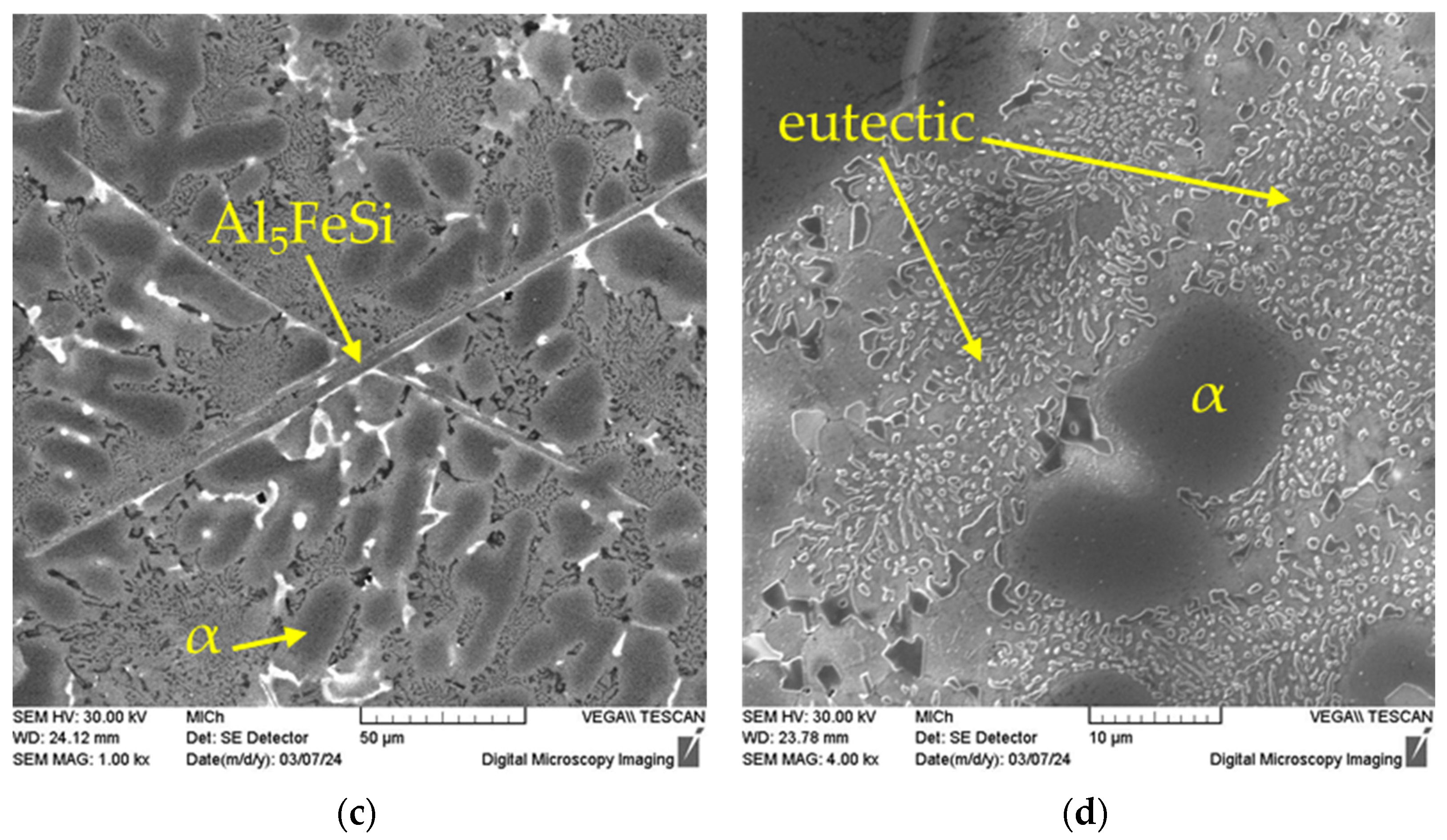
Figure 3.
Microstructure of alloy B: (a) alpha phase and eutectic, etch. Dix–Keller; (b) skeleton-like Al15FeMn3Si2 phases and sludge Al-Fe-Mn phases, etch. Dix–Keller; (c) needle-like Al5FeSi phases, etch. 0.5% HF, SEM; (d) detailed view of eutectic silicon crystals, etch. 0.5% HF, SEM.
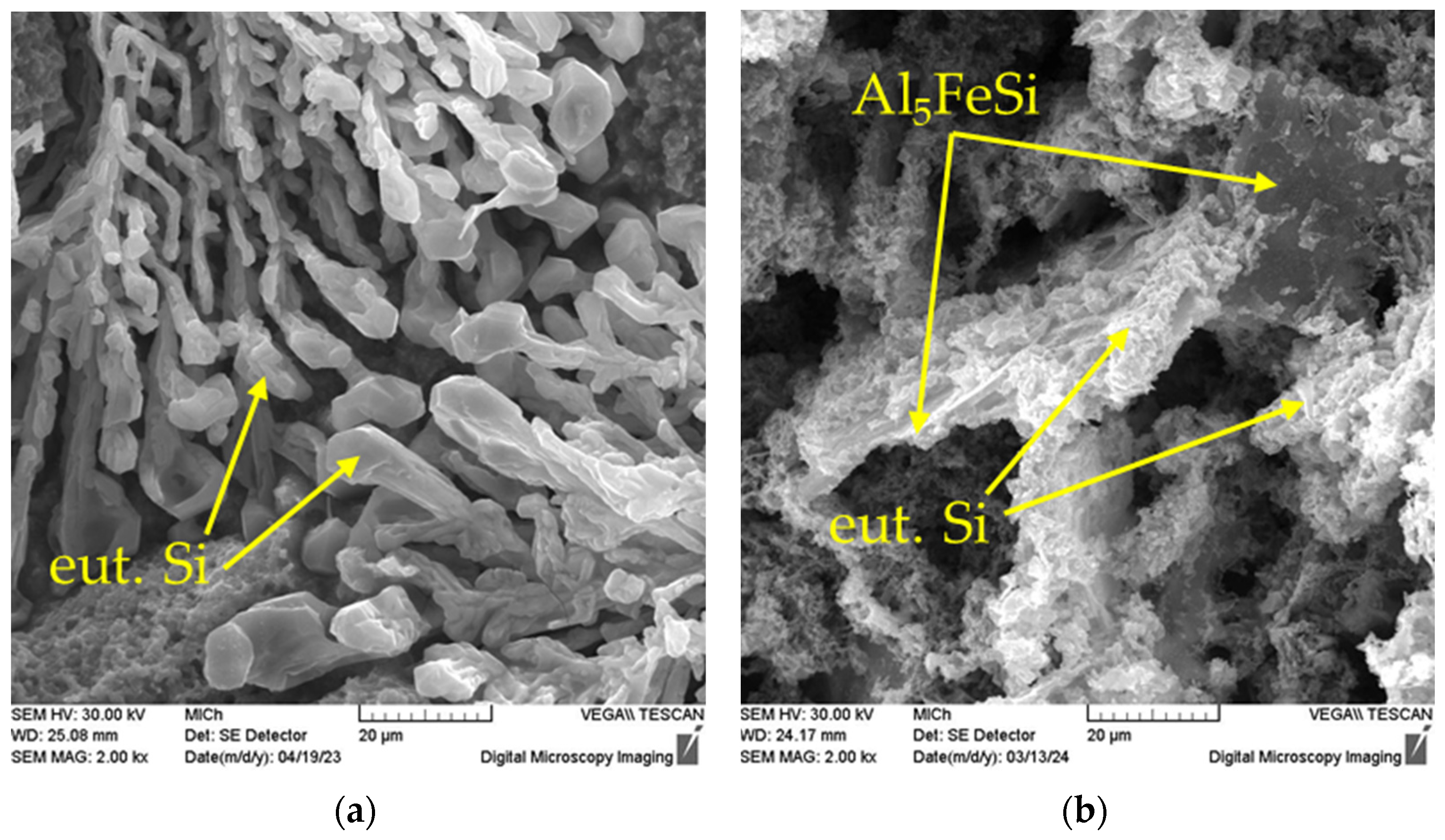
Figure 4.
Detailed view of eutectic silicon morphology, SEM, etch. HCl, deep etching: (a) alloy A; (b) alloy B, SEM.
Figure 5.
The 3D morphology of Fe-rich intermetallic phases, etch. HCl, deep etching: (a) plate-like Al5FeSi phase; (b) Al-Fe-Mn sludge phases, SEM.
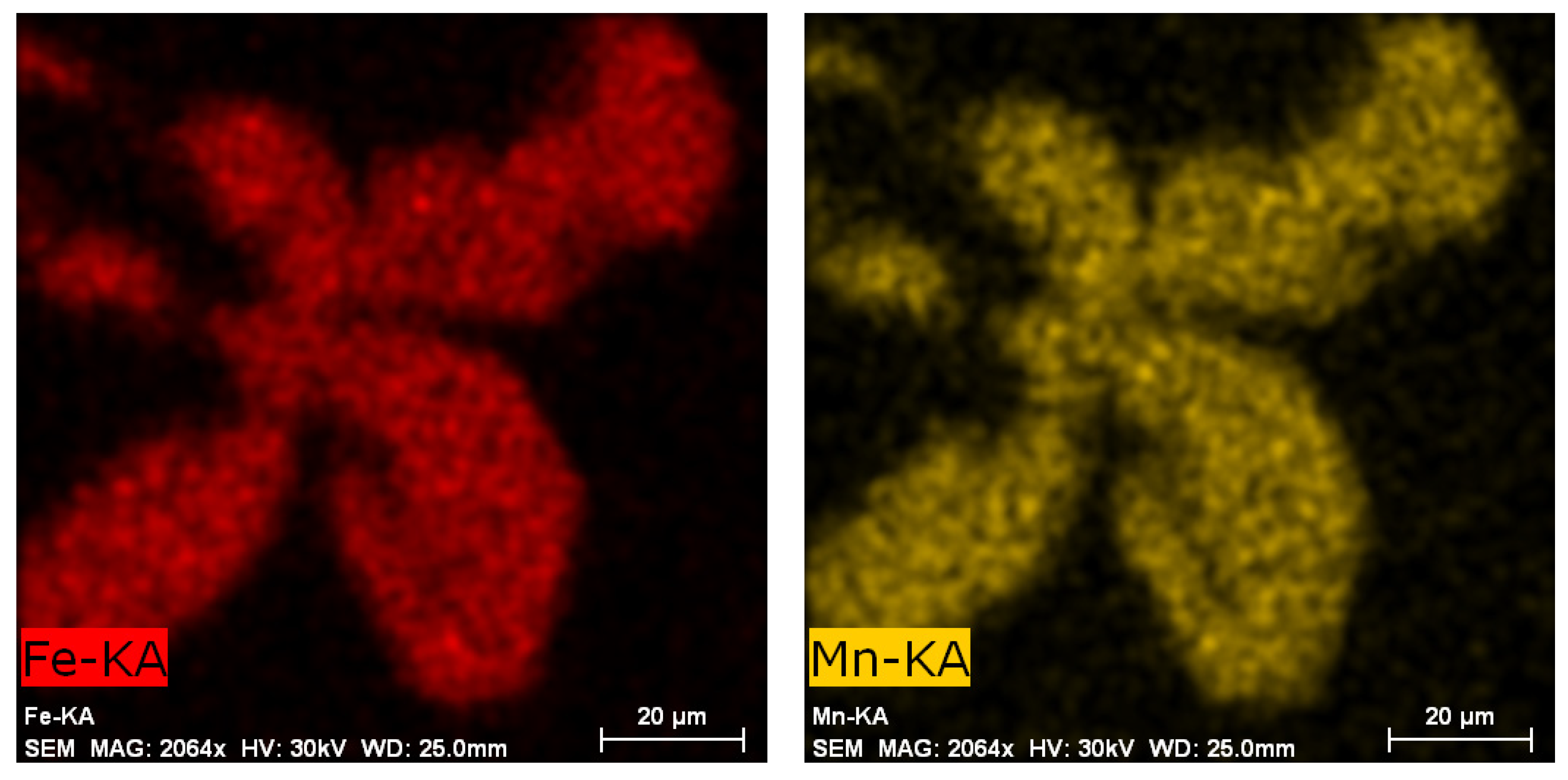
Figure 6.
EDX analysis of sludge phase, etch. 0.5% HF, SEM.
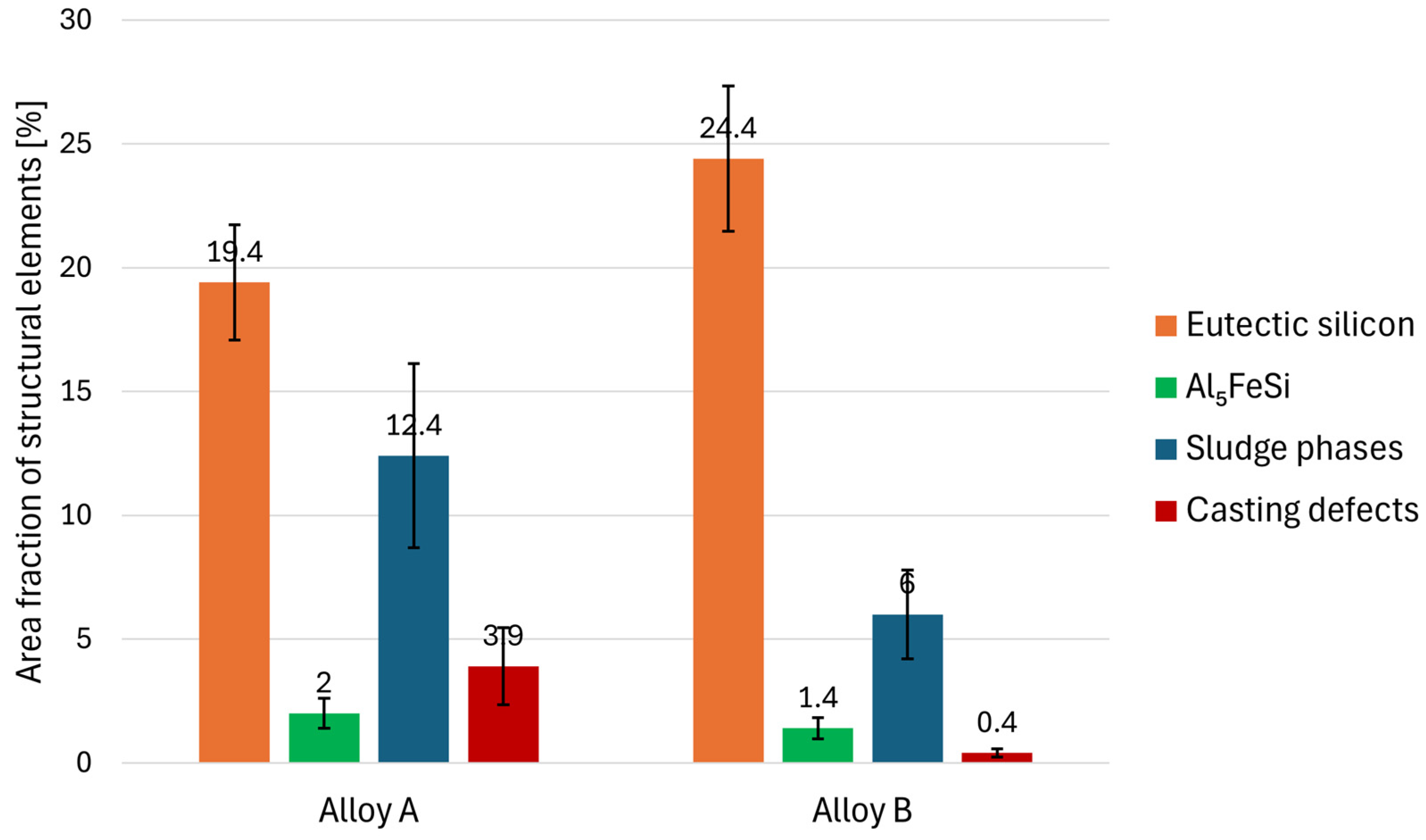
Figure 7.
Results of quantitative analysis—area fraction of structural elements.
Figure 8.
Results of quantitative analysis—size of Al5FeSi and dendrites of α-phase.
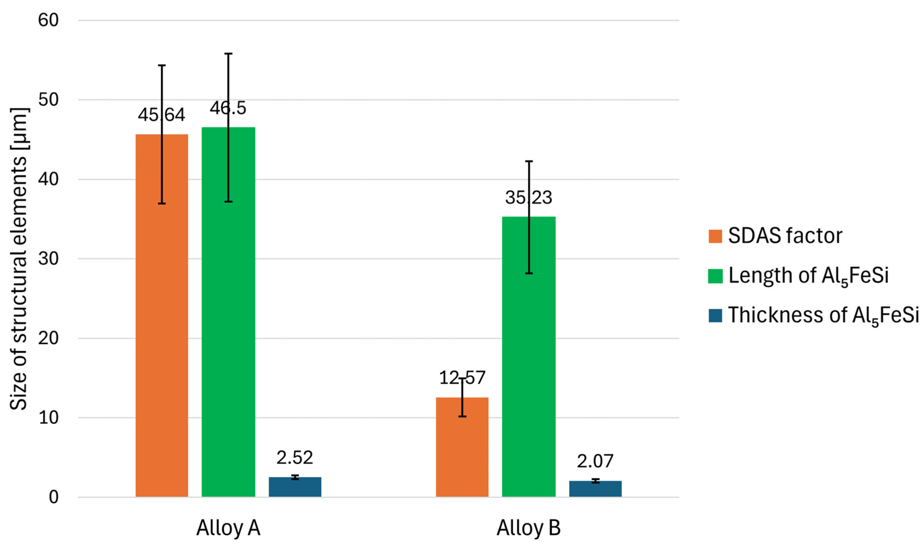
Figure 9.
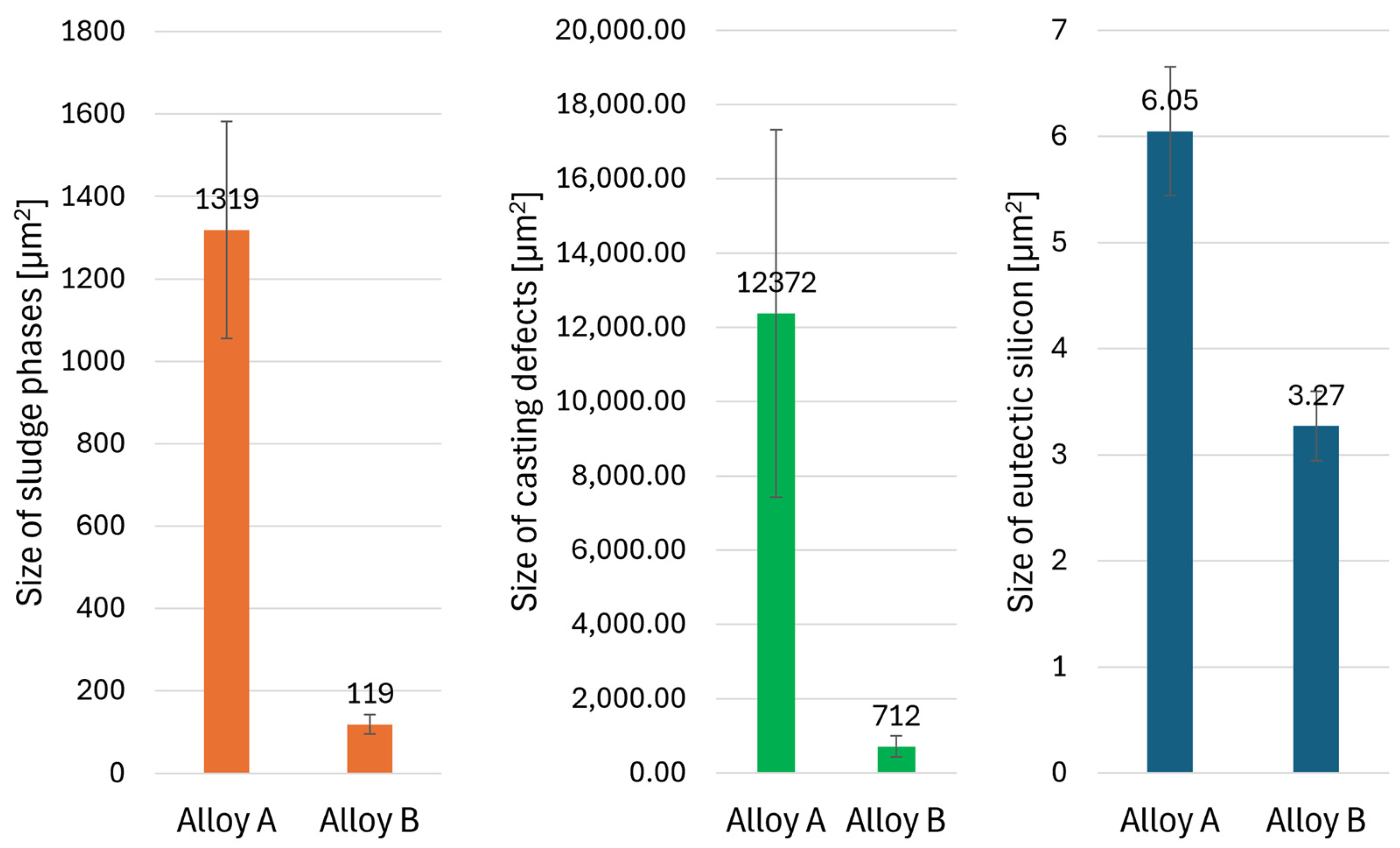
Results of quantitative analysis—size of structural elements.
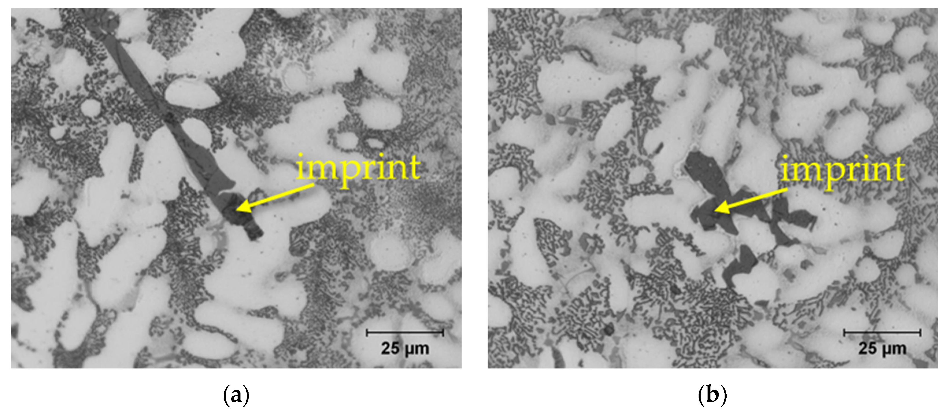
Figure 10.
Representative microhardness measurements of: (a) Al5FeSi phase; (b) sludge phase.
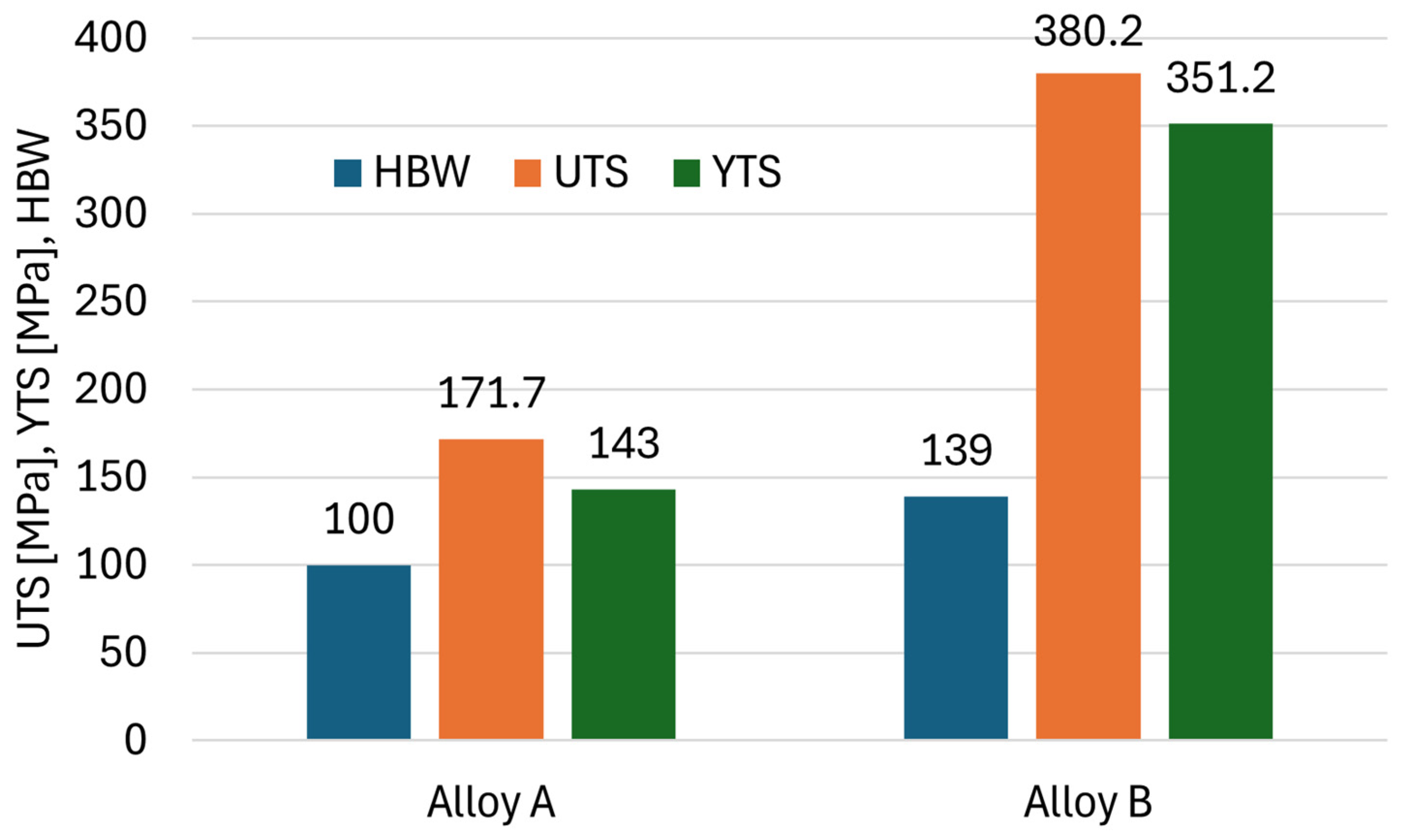
Figure 11.
Brinell hardness, UTS, and YTS of investigated alloys.
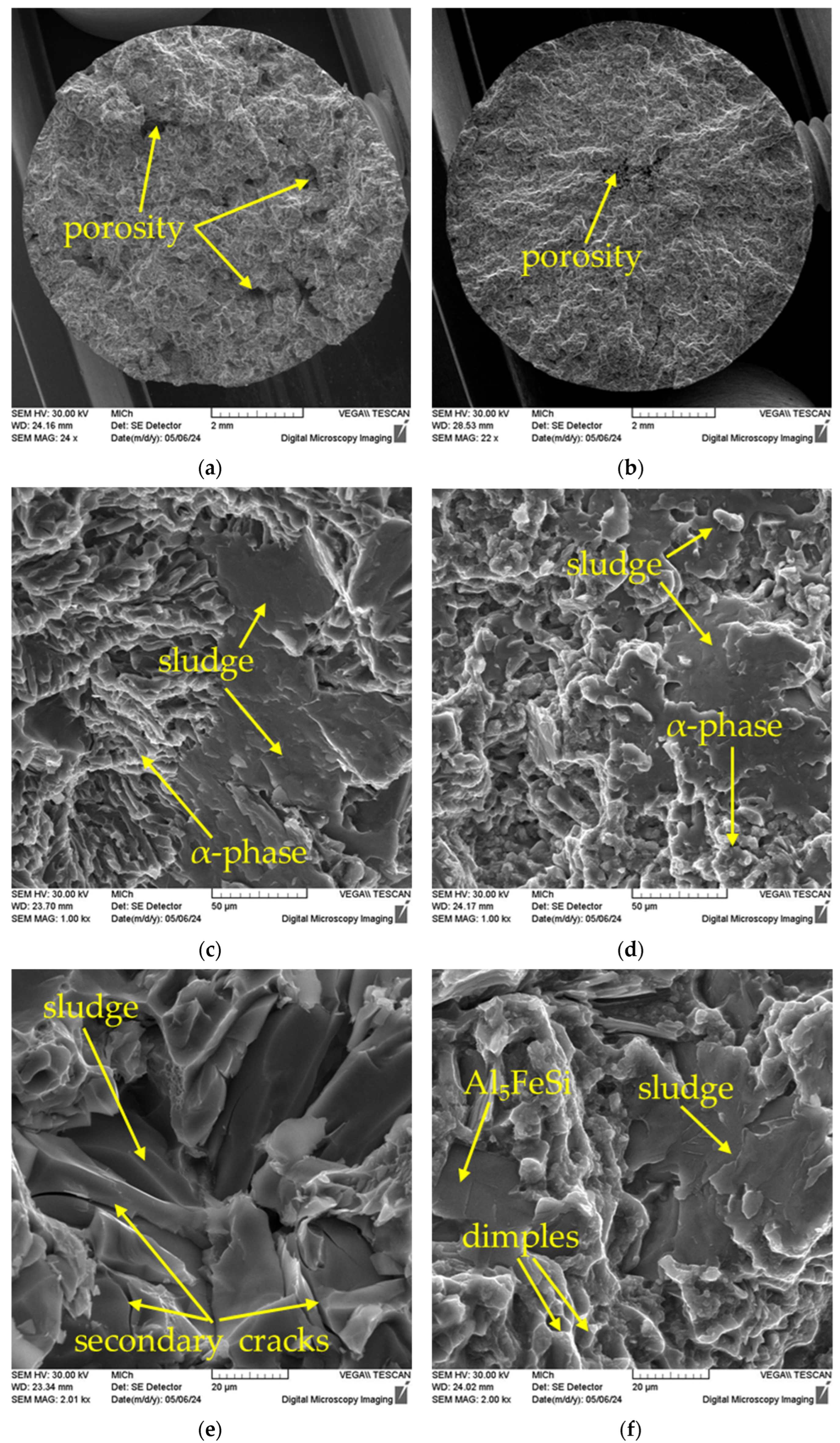
Figure 12.
Fractographic analysis of fracture surfaces, SEM: (a) overall view of A alloy sample; (b) overall view of B alloy sample; (c) detailed view of alloy A; (d) detailed view of alloy B; (e) cracking of sludge phase in Alloy A; (f) cleavage of ferrous phases and dimple morphology of the alpha phase.
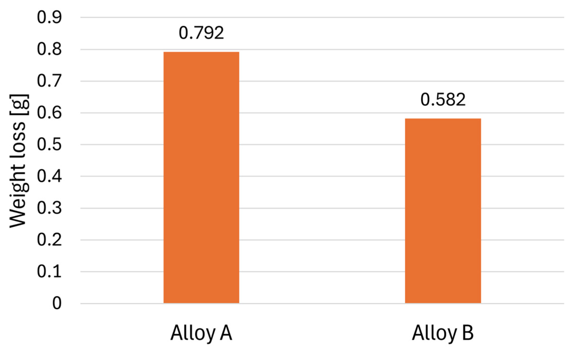
Figure 13.
Results of the Audi test.
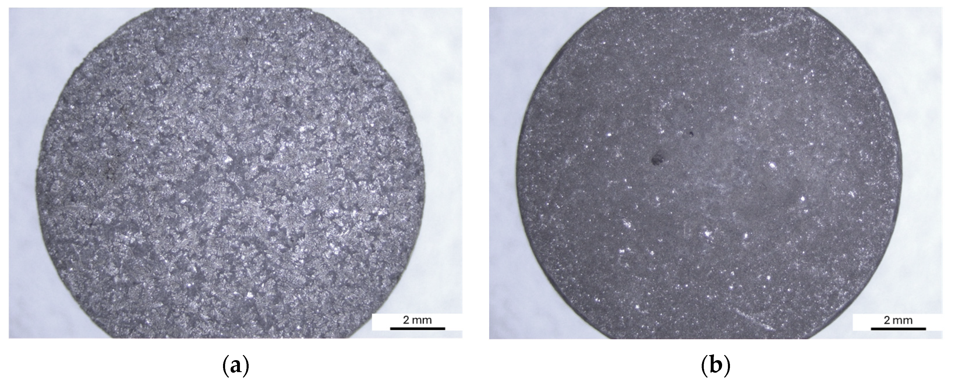
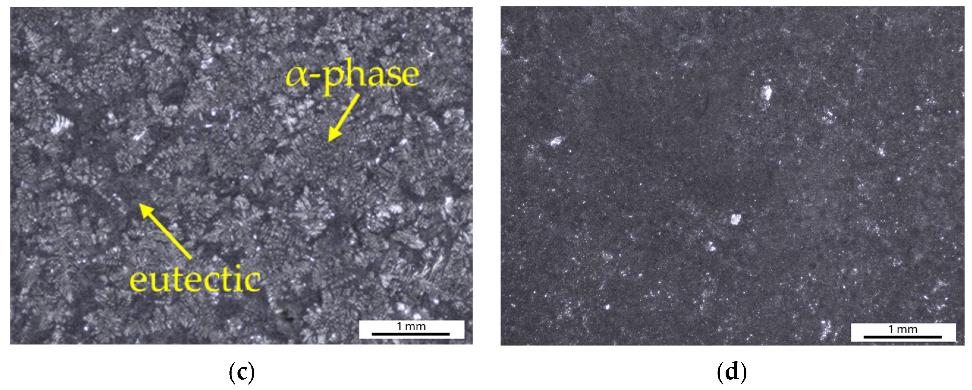
Figure 14.
Surface of samples after the Audi test: (a) Alloy A; (b) Alloy B; (c) detail of Alloy A; (d) detail of Alloy B.
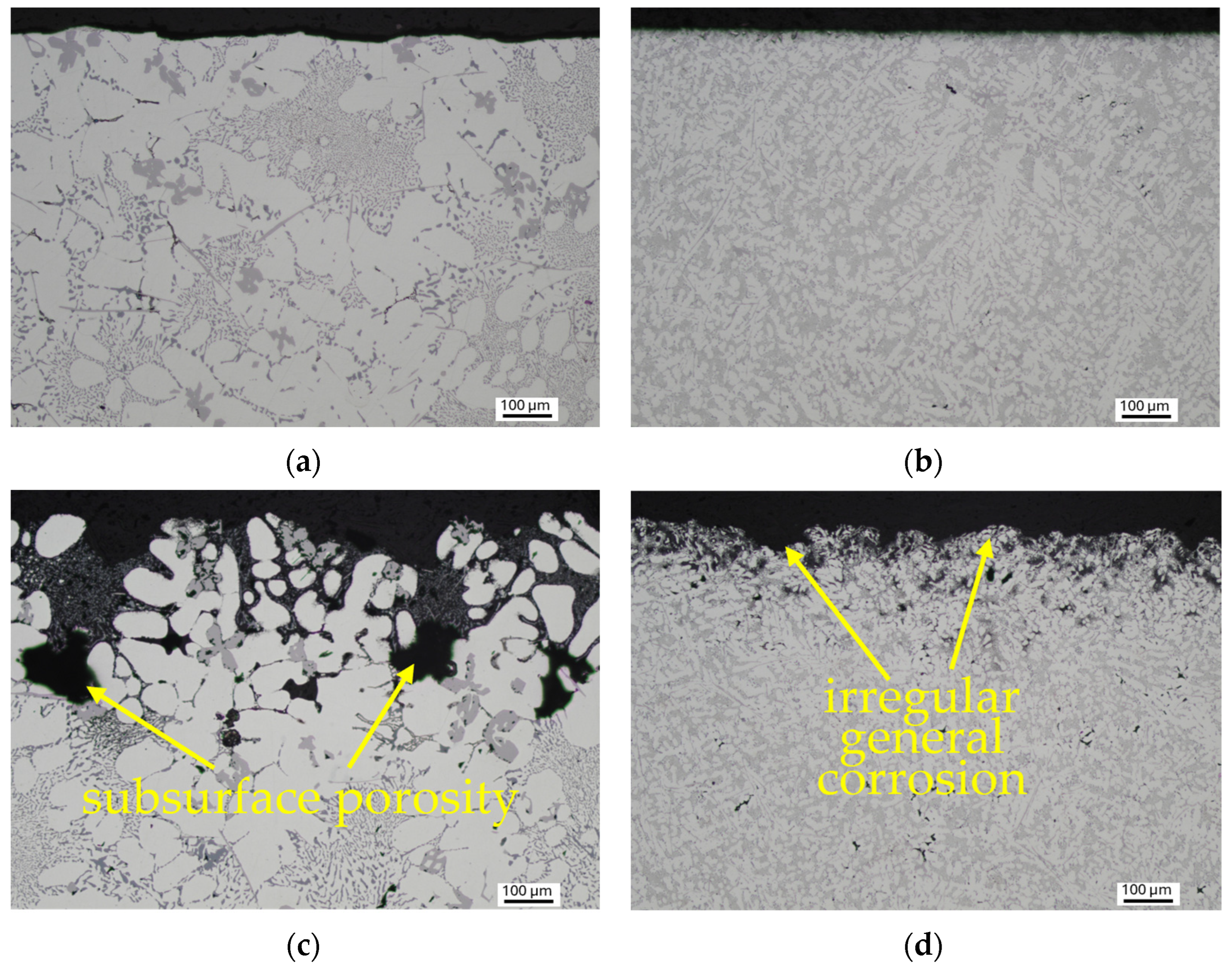
Figure 15.
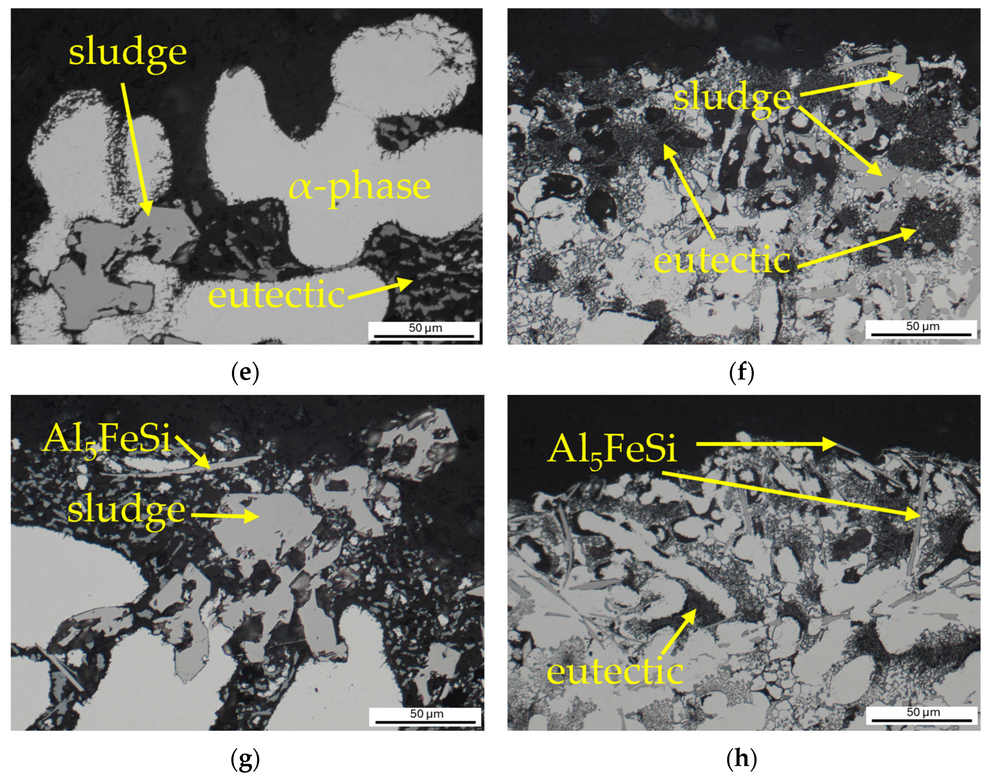
Documentation of the depth and mechanism of corrosion attack: (a) surface of the Alloy A without corrosion; (b) surface of the Alloy B without corrosion; (c) irregular general corrosion in Alloy A; (d) irregular general corrosion in Alloy B; (e) corrosion attack of eutectic in Alloy A; (f) corrosion attack of eutectic in Alloy B; (g) corrosion around intermetallic phases in Alloy A; (h) corrosion around Al5FeSi in Alloy B.
Table 1.
Chemical composition of Unifont alloys [
29] and experimental material [wt.%].
| Alloy | Zn | Si | Mg | Fe | Mn | Cu | Ti | Al |
|---|
| Unifont 90 | 9–10 | 8.5–9.5 | 0.3–0.5 | 0.15 | 0.10 | 0.03 | 0.15 | ball. |
| Unifont 94 | 9–10 | 8.5–9.5 | 0.3–0.5 | 0.40 | 0.40 | 0.03 | 0.10 | ball. |
| A | 9.299 | 8.949 | 0.309 | 0.840 | 0.743 | 0.019 | 0.117 | ball. |
| B | 11.590 | 8.360 | 0.250 | 0.620 | 0.570 | 1.720 | 0.040 | ball. |
Table 2.
Microhardness of individual phases (HV 0.01).
| Alloy | α-Phase | Eutectic | Eut. Silicon | Sludge Phases | Al5FeSi |
|---|
| A | 101 ± 22 | 167 ± 35 | 1184 ± 151 | 1204 ± 146 | 588 ± 170 |
| B | 121 ± 31 | 191 ± 28 | - | 1355 ± 91 | 512 ± 36 |
Table 3.
Overview of mechanical properties.
| Alloy | UTS [MPa] | YTS [MPa] | Ductility [%] | HBW 5/250/10 |
|---|
| A | 171.7 ± 11 | 143 ± 37 | 0 | 100 ± 3 |
| B | 380.2 ± 8 | 351.2 ± 14 | 0.47 | 139 ± 3 |
Table 4.
Overview of the observed characteristics of the investigated experimental alloys.
| | Alloy A | Alloy B |
|---|
| Area fraction of eutectic silicon [%] | 19.4 | 24.4 |
| Area fraction of Al5FeSi [%] | 2 | 1.4 |
| Area fraction of sludge phases [%] | 12.4 | 6 |
| Area fraction of casting defects [%] | 3.9 | 0.4 |
| SDAS factor [µm] | 45.64 | 12.57 |
| Length of Al5FeSi [µm] | 46.5 | 35.23 |
| Thickness of Al5FeSi [µm] | 2.52 | 2.07 |
| Size of sludge phases [µm2] | 1319 | 119 |
| Size of casting defects [µm2] | 12372 | 712 |
| Size of eutectic silicon [µm2] | 6.05 | 3.27 |
| HBW 5/250/10 | 100 | 139 |
| UTS [MPa] | 171.7 | 380.2 |
| YTS [MPa] | 143 | 351.2 |
| Weight loss after Audi test [g] | 0.792 | 0.582 |
| Disclaimer/Publisher’s Note: The statements, opinions and data contained in all publications are solely those of the individual author(s) and contributor(s) and not of MDPI and/or the editor(s). MDPI and/or the editor(s) disclaim responsibility for any injury to people or property resulting from any ideas, methods, instructions or products referred to in the content. |
© 2024 by the authors. Licensee MDPI, Basel, Switzerland. This article is an open access article distributed under the terms and conditions of the Creative Commons Attribution (CC BY) license (https://creativecommons.org/licenses/by/4.0/).


 ,
, 


