Article

Magnetic Hardening of Heavily Helium-Ion-Irradiated Iron–Chromium Alloys

1
Faculty of Science and Engineering, Iwate University, Morioka 020-8551, Japan
2
Faculty of Engineering, Tottori University, Tottori 680-8550, Japan
3
Research Institute for Applied Mechanics, Kyushu University, Kasuga 816-8580, Japan
*
Author to whom correspondence should be addressed.
Metals 2024, 14(5), 568; https://doi.org/10.3390/met14050568
Submission received: 12 April 2024 / Revised: 7 May 2024 / Accepted: 9 May 2024 / Published: 12 May 2024

Abstract

:
This study reports on the magnetic hardening phenomenon of heavily helium ion-irradiated iron–chromium alloys. The alloys are important structural materials in next-generation nuclear reactors. In some cases, problems may arise when the magnetic properties of the materials change due to neutron irradiation. Therefore, it is necessary to understand the effects of irradiation on magnetism. Helium irradiation was conducted as a simulated irradiation, and the effect of cavity formation on magnetic properties was thoroughly investigated. High-quality single-crystal Fe-x%Cr (x = 0, 10, 20) films, with a thickness of 180–200 nm, were fabricated through ultra-high vacuum evaporation. Subsequently, irradiation of 19 dpa with 30 keV He+ ions was conducted at room temperature. X-ray diffraction measurements and electron microscopy observations confirmed significant lattice expansion and the formation of high-density cavities after irradiation. The magnetization curve of pure iron remained unchanged, while magnetic hardening was noticed in iron–chromium alloys. This phenomenon is believed to be due to the combined effect of cavity formation and changes in the atomic arrangement of chromium.

Graphical Abstract

1. Introduction

Iron–chromium alloys have strong resistance to radiation and high temperatures, making them promising candidates for use as structural materials in next-generation nuclear fission and fusion reactors. For example, reduced activation ferritic martensitic steels (Fe-(8–9)%Cr alloys) have been developed for fusion reactor blankets, and research on the irradiation effects on their mechanical properties is progressing [1,2]. When using the blanket in actual fusion reactors, it is necessary to estimate the electromagnetic loads in advance that are generated during plasma disruptions [3,4]. For this purpose, numerical analysis based on finite element modeling (FEM) code is being conducted. However, input magnetic parameters of the unirradiated alloy are used due to the lack of irradiation data. The blanket is exposed to high-energy, high-fluence neutron irradiation during operation, which causes changes in atomic configuration [5] and potentially alters magnetic properties. Nevertheless, these behaviors have not been fully clarified.
When investigating the effects of high-fluence irradiation damage, neutron irradiation experiments using nuclear reactors are time-consuming and have limited experimental flexibility. As an alternative approach, ion irradiation that causes cascade damage similar to neutron irradiation is useful [6]. In the case of ion irradiation, the damaged region is limited to the surface layer of the specimen due to the short penetration depth of ions. When ion irradiation is applied to bulk specimens, it becomes challenging to distinguish the magnetic characteristics of the damaged and undamaged regions, which complicates the evaluation of the irradiation effects. In contrast, using thin film specimens makes assessment easier because the entire specimen is damaged. From this perspective, ion-irradiated film specimens are beneficial for understanding the effects of severe irradiation on magnetic properties. It has been reported that the saturation magnetization significantly increased when 60 nm Fe films were subjected to 490 kV Fe+ irradiation at room temperature (RT) up to several tens of displacements per atom (dpa) [7]. This phenomenon is believed to be caused by void clusters formed by cascade damage, leading to an increase in magnetization due to local magneto-volume effects. This can be considered an example of severe irradiation affecting the magnetic properties.
On the other hand, when examining iron–chromium alloys where chromium is introduced to pure iron, it is important to consider not only the formation of dislocation loops and void clusters caused by irradiation but also the changes in the arrangement of chromium atoms. By thermal aging, the Fe-Cr solid solution is known to undergo phase separation into Fe-rich and Cr-rich phases at high temperatures [8], which affects the magnetization process of the alloys [9,10]. It has been reported that phase separation is enhanced by irradiation when the irradiation flux is relatively low and the cascade mixing effect is small, even in the low-temperature range where separation does not occur by thermal aging [11,12]. In the studies investigating the magnetic properties of ion-irradiated Fe-(5–20)%Cr films, an increase in coercivity and magnetization was reported [13,14,15]. The irradiation-enhanced phase separation is considered the reason behind these phenomena. However, direct verification from microstructural characterization has not been conducted, and the mechanism is not fully understood.
In fusion reactor environments, it is also important to consider the effect of cavities (voids and bubbles) formed by the accumulation of helium due to nuclear transmutation during neutron irradiation [16,17]. Nevertheless, the effect of these cavities on magnetic characteristics had not been previously examined. In our previous study, we investigated the magnetic properties of iron films irradiated by helium ions at RT. As a result, we have discovered that the magnetism of iron is highly robust to the formation of high-density nanoscale cavities [18]. In this study, we investigated the effect of the same irradiation on the magnetic properties of iron–chromium alloy films containing 10% and 20% chromium. The results revealed that the alloys are magnetically hardened and less resistant to irradiation compared to pure iron. We will present these experimental findings and discuss the mechanism behind the hardening while comparing it to the behavior of iron.

2. Experimental Procedures

2.1. Specimen Preparation

In this study, epitaxially grown single crystal films were fabricated as specimens using ultra-high vacuum (UHV) evaporation, followed by helium ion irradiation. The methods are summarized below.
To produce high-quality iron–chromium alloy films, a MgO (001) single crystal was used as the substrate because of its favorable lattice matching with the body-centered cubic (BCC) structure of the alloy. To address the hygroscopic nature of MgO, the substrate underwent a heat treatment at 1273 K for 12 h in an oxygen environment before thin film fabrication [18]. This process aims to eliminate the surface alteration layer and ensure a flat substrate at the atomic level. Subsequently, the treated substrate was placed in a UHV chamber with a base vacuum of 2 × 10⁻⁷ Pa, where it was further heat-treated at 873 K. Fe-x%Cr (x = 0, 10, 20) films, with a thickness ranging from 180 to 200 nm, were deposited onto the substrate using the electron beam evaporation technique while keeping the substrate at RT (UHV deposition system, EIKO Corp., Tokyo, Japan). During the deposition process, the film thickness was monitored using a calibrated quartz crystal oscillator film thickness gauge, while the crystal growth was observed in real-time through reflection high-energy electron diffraction (RHEED). After deposition, a 15 min heat treatment at 873 K was conducted in UHV to achieve high-quality thin films.
The film specimens were irradiated with 30 keV He+ at RT using a light-element accelerator system at the Research Institute for Applied Mechanics of Kyushu University. The ion flux was 1.5 × 10¹³ ions/(cm2s), and the total dose was 3.0 × 10¹⁷ ions/cm2. Figure 1 shows the damage and residual helium profiles of Fe-20%Cr alloy, which were calculated using the Stopping and Range of Ions in Matter (SRIM) code with a threshold energy of 40 eV [19]. Most of the damage and residual helium are distributed widely throughout the thickness of the film. The highest damage level is located at a depth of 95 nm, with an estimated approximately 19 dpa.

2.2. Characterization of Microstructure and Magnetism

In order to investigate the microstructures and magnetic properties of film specimens before and after irradiation, the following experiments were conducted.
The crystal structure and orientation relationship of the film were investigated using electron backscatter diffraction (EBSD, Oxford Instruments HKL Channel5, Oxford Instruments, Abingdon, UK), both before and after irradiation. The diffraction profile perpendicular to the film plane was measured using a conventional X-ray diffraction (XRD) θ–2θ measurement system (Rigaku Ultima IV with a CuKa radiation, Rigaku Corp., Tokyo, Japan). Furthermore, thin sections were cut from both the unirradiated and irradiated specimens using the micro-sampling method of the focused ion beam of 30 keV Ga+ (FIB, MI-4050, Hitachi High-Tech Corp., Tokyo, Japan). Transmission electron microscopes were used to examine the microstructural characteristics of the cross-section of the film. In order to analyze the distribution of elements, a transmission electron microscope with an energy dispersive spectroscopy (EDS) attachment and aberration correction capability was utilized (TEM, JEM-2100 and ARM200FC, JEOL Ltd., Tokyo, Japan).
Magnetization curves were obtained at RT using a vibrating sample magnetometer (VSM, Toei VSM-5-15, Toei Industry Co., Ltd., Tokyo, Japan). The specimen holder was adjusted to apply a magnetic field within the plane of the film. By rotating the specimen on the holder, magnetization curve data were collected in both the easy and hard magnetization orientations. The maximum magnetic field strength applied during the measurement was around 5 kOe.

3. Results

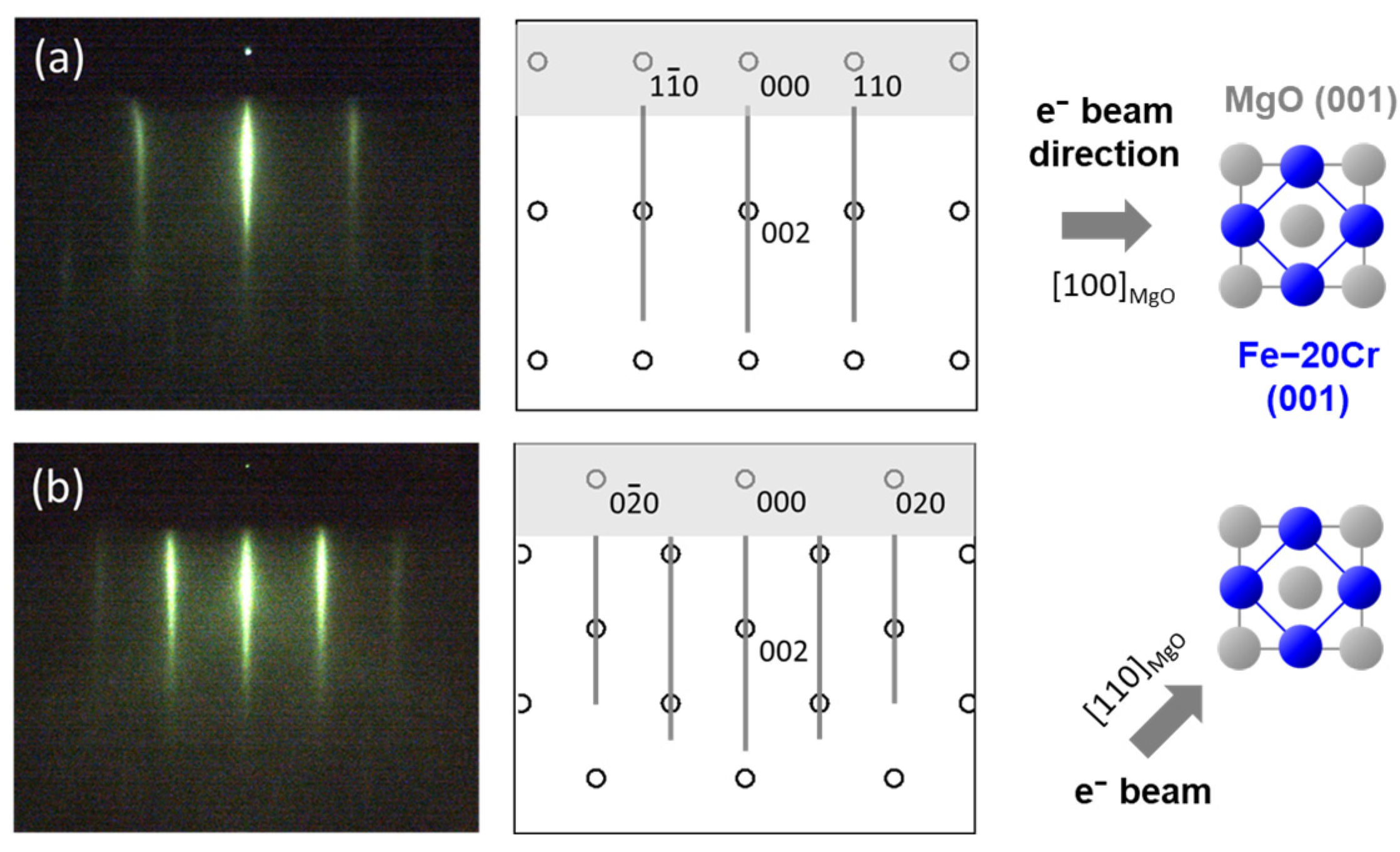
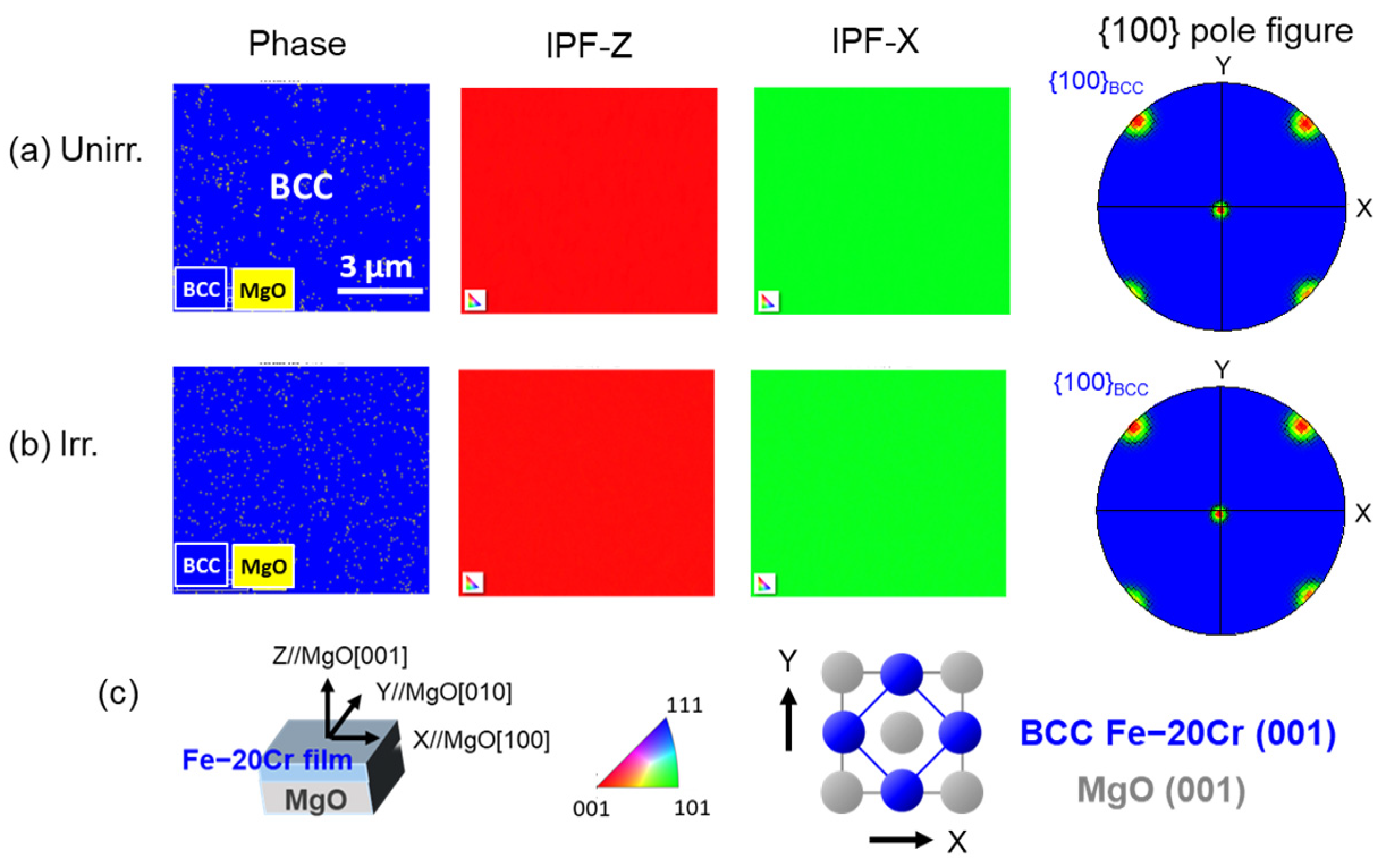
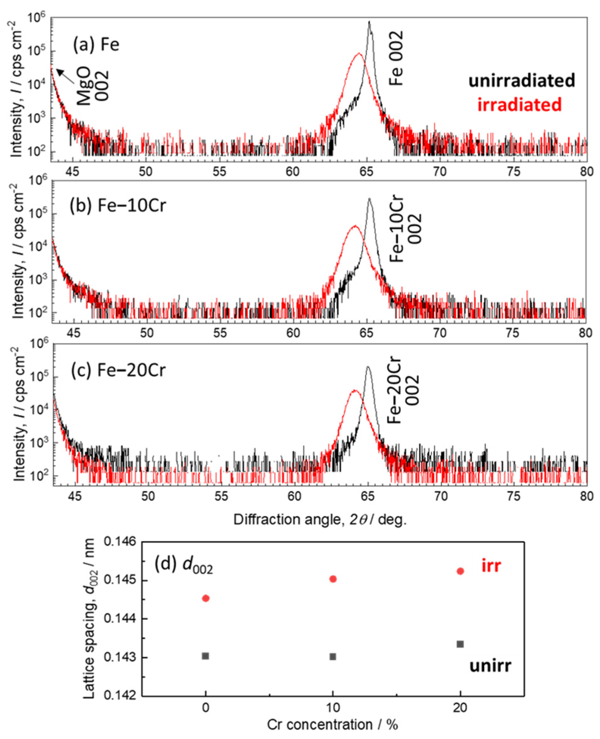
3.1. Epitaxial Structure and Lattice Expansion

Figure 2 shows the in situ observed RHEED patterns and schematic diagrams of an Fe-20%Cr film that was heat-treated at 873 K after a 200 nm deposition. The electron beam is incident in the (a) [100]MgO direction and (b) [110]MgO direction. The diffraction patterns are streaky, and the distance between streaks in Figure 2a is wider than that in Figure 2b. These patterns indicate that the film’s surface is flat, and the BCC structure of Fe-20%Cr (001) was epitaxially grown with a 45-degree rotation in relation to the MgO (001) lattice. Similar diffraction patterns were also observed in an Fe-10%Cr film. The orientation relationship between the film and the substrate is as follows.
BCC Fe-Cr (001) [110]//MgO (001) [100]
Figure 3 shows the results of structural observations of an Fe-20%Cr film obtained through ex situ EBSD measurement. These figures display phase maps, inverse pole figure (IPF) maps, and {100}BCC pole figures of both unirradiated (Figure 3a) and irradiated (Figure 3b) films, respectively. Furthermore, Figure 3c illustrates a schematic drawing of the epitaxial relationship. The results of the unirradiated film (Figure 3a) are consistent with the findings of RHEED observations (Figure 2), and these remain unchanged after irradiation (Figure 3b), suggesting that irradiation does not affect the crystal structure and orientation of the film. Similar results have been confirmed for Fe-10%Cr thin films, as well as for pure iron, as reported in the previous study [18].
Figure 4 shows out-of-plane XRD profiles of Fe [18], Fe-10%Cr, and Fe-20%Cr films, covering a diffraction angle 2θ range from 43.5 degrees to 80 degrees, and d002 lattice spacing. The intensity of the MgO 002 peak (2θ = 42.92 degrees) from the single crystal substrate is excessively high. Therefore, we measured the profile from the angle of the shoulder on the right side of the MgO 002 peak and investigated in detail the BCC 002 peak of the film, as expected from RHEED and EBSD measurements. After irradiation, the intensity of the BCC 002 peak decreased, the peak width broadened, and the peak position shifted to lower angles (Figure 4a–c). These findings indicate that the lattice spacings perpendicular to the film plane have broad distributions and elongation. Figure 4d provides a summary of the d002 lattice spacings derived from the XRD profiles. After irradiation, the lattice spacing of the Fe-20%Cr film increased by 1.3% in the out-of-plane direction. In the present study, the lattice spacings along the in-plane direction of the Fe-Cr films were not measured. It is presumed that they have changed very little due to the effect of substrate constraint, as reported in the previous study on iron films [18].

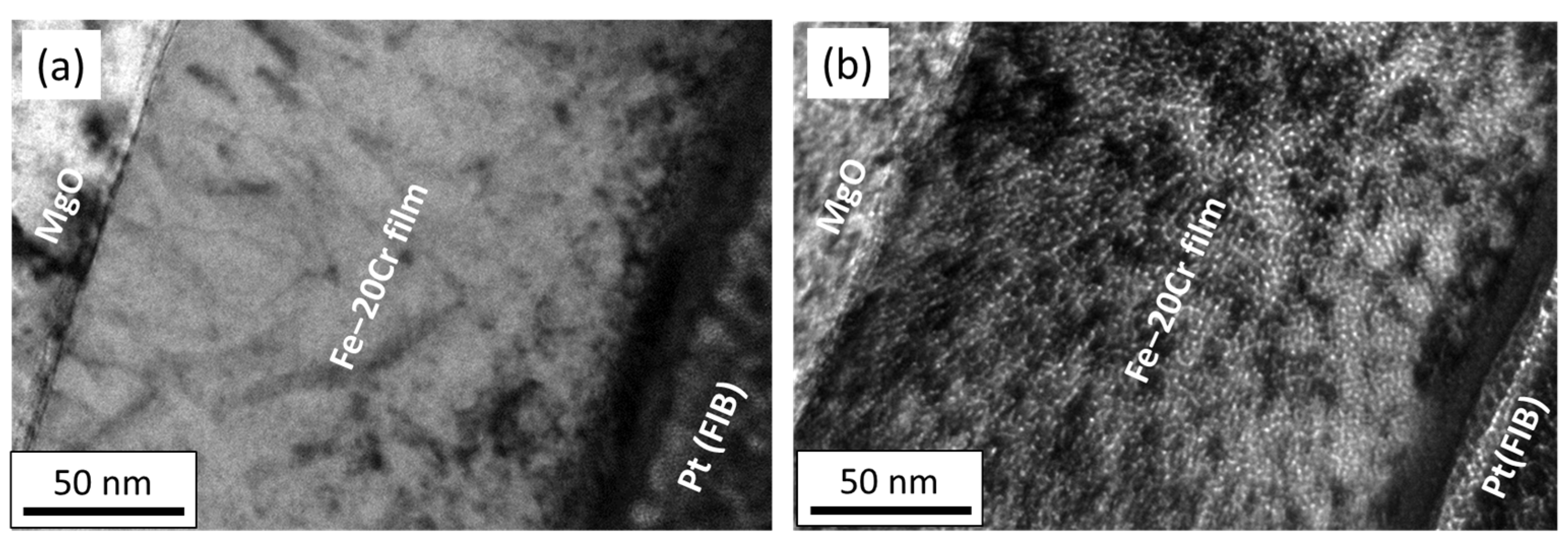
3.2. Formation of Cavities

Figure 5 shows TEM images of (a) unirradiated and (b) irradiated Fe-20%Cr specimens. The under-focused image of the irradiated specimen in Figure 5b exhibited numerous bright contrasts at a nanometer scale. Similar contrasts were observed in an iron film irradiated with He+ under the same conditions [18], where the irradiation led to the formation of cavities, likely helium bubbles. The number density of the cavities, calculated assuming the TEM specimen thickness of 100 nm, was 1.2 × 1024/m3. It was noted that the number density and size of the cavities in the Fe-20%Cr film closely resemble those observed in the Fe film. In this study, TEM observation has not been conducted on the Fe-10%Cr film. However, since the similar lattice expansion has been confirmed in Fe-10%Cr (Figure 4), it indicates that the film possesses similar microstructures with cavities of high number density.
In the introduction, we mentioned the possibility of phase separation induced by irradiation. To verify whether this phenomenon is occurring, we examined the composition distribution of the cross-section of an Fe-20%Cr film. Figure 6a is a STEM-BF image, while Figure 6b–e are EDS elemental mappings of Fe, Cr, Pt, and Ga, respectively. In Figure 6b,c, noticeable distributions in iron and chromium concentrations are not confirmed at this scale of observation. The cavities in this specimen are on a nanometer scale and are densely distributed. Considering that the thickness of the cross-sectional specimen is around 100 nm, there may be an overlapping and averaging of fine structures along the thickness direction. To elucidate the phase separation behavior induced by irradiation, high-resolution atom probe measurements are the best approach, although there are challenging issues that will be discussed later.

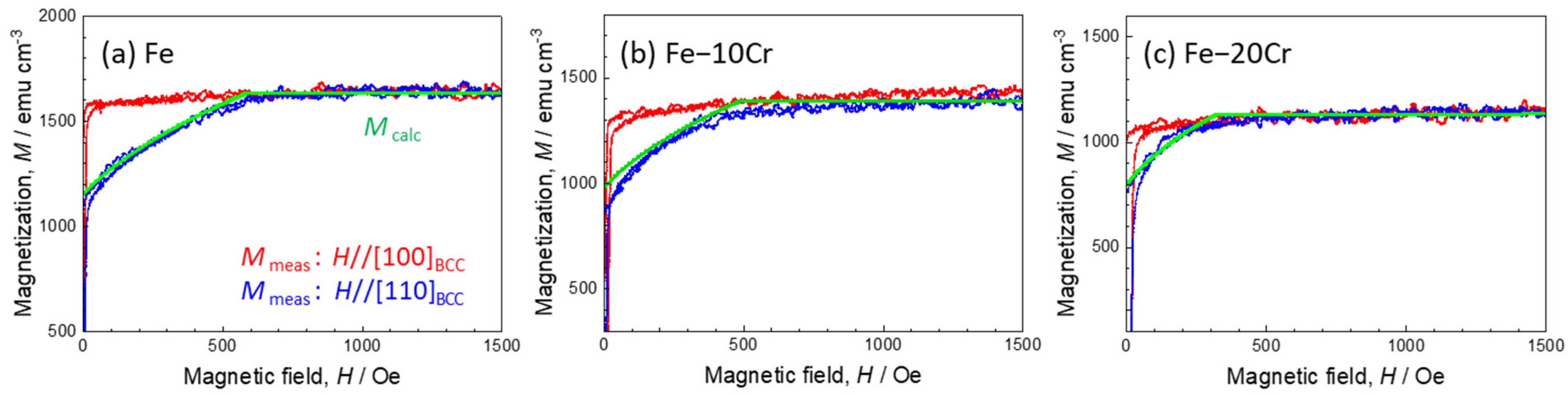
3.3. Irradiation Effects on Magnetization Curves

The magnetization of the specimens was measured before and after irradiation using a VSM. Figure 7a–c show the magnetization curves of unirradiated Fe, 10%Cr, and 20%Cr films, while Figure 7d,e show irradiated ones. In the calculation of magnetization, a thickness of 200 nm was used for the Fe and Fe-10%Cr films, and 180 nm for the Fe-20%Cr film. The red lines represent the curves when a magnetic field is applied in the [100] BCC direction, while the blue lines represent the curves when the field is applied in the [110] BCC direction. In the case of the unirradiated specimens (Figure 7a–c), all curves indicate that the [100]BCC and [110]BCC are the easy and hard magnetization directions, respectively, consistent with the characteristic of magnetocrystalline anisotropy in bulk iron. The addition of chromium to iron leads to a decrease in saturation magnetization and a reduction in the difference between the easy and hard directions (Figure 7b,c). As reported in the previous study [18], the magnetization curves of the Fe film remain unchanged after irradiation, indicating the resilience of its magnetic properties against cavity formation (Figure 7a,d). In contrast, the behavior of the chromium-containing alloys exhibits significant differences. After irradiation, the magnetization curve exhibited an inclination, making it difficult to reach magnetization saturation (Figure 7e,f). This effect is more pronounced in the Fe-20%Cr alloy with a higher chromium concentration, where the saturation magnetic field reaches around 1 kOe (Figure 7f).
First, the magnetization curves of the unirradiated films in the hard direction are analyzed, and then compared with those of the irradiated films. The magnetization is assumed to be confined within the (001) film plane (x-y plane) due to the demagnetizing effect. By considering the magnetic field applied along the [110]BCC direction, the angle between the magnetization direction and [100]BCC is represented as θ, and the saturation magnetization is denoted as M s . The direction cosine α i and magnetization M follow Equation (1). Using the crystalline magnetic anisotropy constant K i , the crystalline magnetic anisotropy energy E A is expressed as Equation (2), and the total energy E is determined by Equation (3). Minimization of this energy yields the magnetic field H , as described by Equation (4). The magnetization curve can be calculated using Equations (1) and (4). Figure 8 shows an enlarged view of the first quadrant of the magnetization curve of the unirradiated films (Figure 7a–c) and the calculated curve. The values of M s and K 1 used in the calculation are summarized in Table 1. With an increase in Cr concentration, the values of M s and K 1 decrease, consistent with the trends observed in bulk alloys [19,20]. The saturation field H S in the hard direction is determined by H S = 2 K 1 / M s from Equation (4). The H S value of the unirradiated Fe-20%Cr film is 319 Oe (Figure 8c), whereas that of the irradiated film is 1 kOe (Figure 7f), which is more than three times larger. The mechanism of this phenomenon will be discussed in the next section.
α 1 , α 2 , α 3 = c o s θ , s i n θ , 0 M = M s c o s π / 4 θ
E A = K 1 α 1 2 α 2 2 + α 2 2 α 3 2 + α 3 2 α 1 2 + K 2 α 1 2 α 2 2 α 3 2 = K 1 1 c o s 4 θ / 8
E = E A M H = K 1 1 c o s 4 θ / 8 M s H c o s π / 4 θ
H = K 1 s i n 4 θ / 2 M s s i n π / 4 θ

4. Discussion

In this section, we will discuss the magnetic hardening phenomenon of Fe-Cr films induced by irradiation. When subjected to helium ion irradiation, both Fe and Fe-Cr films exhibited the formation of cavities with similar number densities, accompanied by an increase in the lattice spacing perpendicular to the film plane. Notably, no significant changes were observed in the magnetization curves of the pure iron film. However, an enhancement in the saturation magnetic field was detected in the Fe-Cr films, particularly in the specimen with higher chromium concentrations. This phenomenon is believed to be linked to the presence of chromium atoms, suggesting that the rearrangement of chromium atoms caused by irradiation plays an important role. However, this hypothesis has not been directly verified through microstructural observations. Therefore, a phenomenological approach is adopted based on the analysis of the magnetization curve shape to discuss several mechanisms that could potentially cause the hardening.
Various models have been proposed for analyzing the shape of the magnetization hysteresis curve [21,22]. Here, a phenomenological analysis using the hyperbolic tangent function is conducted. Assuming that the magnetization curve of the irradiated Fe-20%Cr film can be decomposed into two components, one with low coercivity and hard magnetization m 1 , and the other with high coercivity and rectangular shape m 2 , the saturation magnetization, M s , is assumed to be the same as that of the unirradiated Fe-20%Cr film (1.13 × 10³ emu/cm3 in Table 1), with two components existing with volume fractions v 1 and v 2 . The upper side (magnetic field decreasing side) of the curve is represented as m i + , and the lower side (increasing side) is represented as m i . The total magnetization M ± is calculated by adding the two as shown in Equation (5). The variable x i ± of the hyperbolic tangent function is expressed in terms of the effective magnetic field H e f f , the shift parameter H c i , and the normalized variable σ i in Equation (6). Here, the H e f f is expressed in terms of the external field H e x t and the demagnetization factor N i in Equation (7). Figure 9 shows the magnetization curve derived from this model, and the values of the parameters are summarized in Table 2.
M ± = m 1 ± + m 2 ± = v 1 M s t a n h x 1 ± + v 2 M s t a n h x 2 ±
x i ± = H e f f ± H c i / σ i
H e f f = H e x t N i m i ±
The shape of the magnetization curve of the irradiated Fe-20%Cr film can be well reproduced by the superposition of two components, m 1 and m 2 (Figure 9). The volume fraction of the two magnetization components is 0.65 and 0.35, respectively. The presence of the characteristic hard magnetization component m 1 in this model is attributed to the demagnetizing field effects. In ferromagnetic materials, a significant demagnetizing field arises when the cross-sectional area is large in the field direction, which results in magnetic hardening. For example, in small-shaped ferromagnetic materials fabricated by lithography processing where strong and weak demagnetizing field regions coexist, a magnetization curve with a shape similar to Figure 9a can be obtained [23,24]. It has been reported that the cavities in irradiated Fe-Cr alloys tend to become covered with chromium-rich regions due to segregation [25,26]. When the chromium concentration of Fe-Cr alloy increases above 70%, the Curie temperature of the alloy decreases below room temperature, making it non-magnetic [20]. If the cavities enclosed by non-magnetic shell regions are interconnected and the ferromagnetic matrix is fragmented, the demagnetizing field effects may be intensified, resulting in magnetic hardening.
Apart from the aforementioned demagnetizing field effects, there are other factors that could play a role in magnetic hardening. While the precise relationship with the microstructures remains ambiguous, potential factors such as vertical magnetic anisotropy and/or antiferromagnetic (AF) coupling might be implicated. The positive magnetostriction constant of bulk Fe-Cr alloy increases with higher chromium concentrations [27]. The irradiated Fe-Cr films exhibited expansion perpendicular to the film plane, which may induce out-of-plane anisotropy and potentially hinder in-plane magnetization. As another possibility, if the AF coupling exists in the film, a well-known phenomenon observed in Fe layers of Fe/Cr/Fe multilayers, a large magnetic field is required to disrupt the coupling [28]. If iron-rich regions in irradiated Fe-Cr films exhibit some kind of AF coupling with each other through chromium-rich regions, the magnetization process may be hindered, leading to magnetic hardening.
All the discussions described above are speculations based on the shape analysis of the hysteresis curve, and there has been no direct experimental confirmation from microstructural viewpoints. Preliminary experiments are being conducted on irradiated films using atom probes to accurately evaluate nano-scale structures. But we found there are currently some challenges. When there are high-density small holes in specimens, careful corrections are required for elemental analysis due to the differences in field evaporation behaviors between the hole regions and the matrix [29]. This complicates the process of conducting precise composition analysis. Furthermore, although not mentioned in this discussion, there are reports to consider regarding the influence of short-range order on the magnetism [30]. Considering these factors, it will be essential to conduct a more thorough analysis of the atomic arrangement of chromium in upcoming research.
The current irradiation was conducted at room temperature as part of the initial study, whereas the operating temperature range of the blanket would be higher (573–823 K). This could potentially result in enhancing phase separation and cavity coarsening. By altering the irradiation conditions, such as temperature, fluence, and flux, and conducting detailed microstructural analysis of iron–chromium films, useful magnetic data could be collected for FEM calculations of electromagnetic loads on the blanket. These studies will deepen the understanding of the magnetic behaviors of ferritic alloys irradiated in fusion reactor environments.

5. Conclusions

In this study, the effects of helium ion irradiation on the microstructures and magnetic properties of pure iron and iron–chromium alloys (10%Cr and 20%Cr) were thoroughly investigated. The epitaxial bcc iron and iron–chromium films were irradiated with 30 keV He+ up to 3.0 × 10¹⁷ ions/cm2 at RT. Microstructural observations were conducted using XRD and TEM, and magnetization curve measurements were performed using a VSM before and after irradiation. The results obtained are as follows:
(1)
The helium irradiation did not affect the crystal structure and orientation of epitaxially grown films.
(2)
In all specimens, an approximate 1% increase in the lattice distance perpendicular to the film plane was confirmed. Furthermore, small high-density cavities with a similar number density were observed in both Fe and Fe-20%Cr films.
(3)
After irradiation, significant magnetic hardening was observed in the magnetization curves of Fe-10%Cr and 20%Cr films, whereas no change was confirmed in the Fe film. The saturation magnetic field of Fe-20%Cr reached around 1 kOe.
(4)
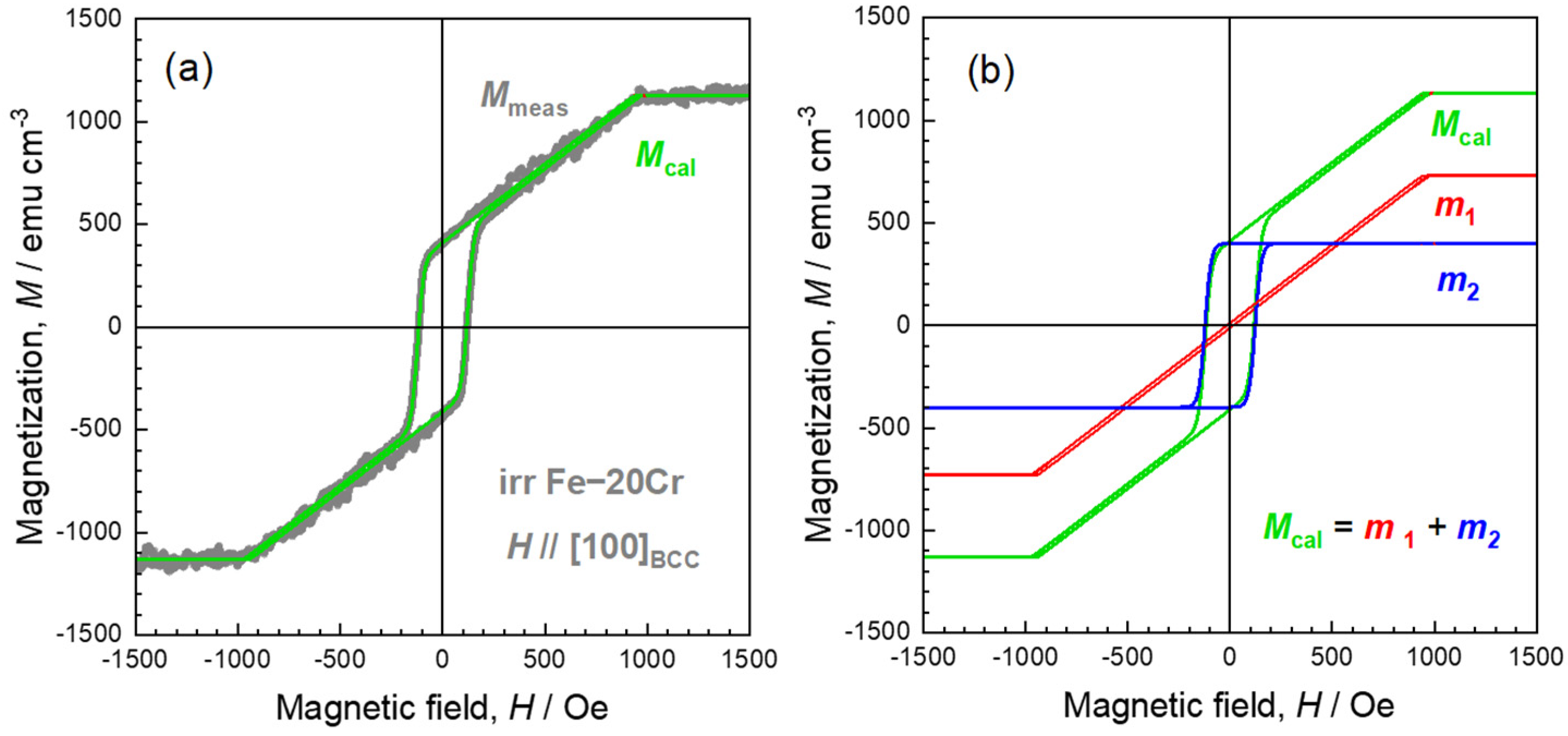
The magnetization curve of the irradiated Fe-20%Cr film can be decomposed into two components: one characterized by low coercivity and hard magnetization, and the other exhibiting high coercivity and a rectangular shape.
(5)
The magnetic hardening in iron–chromium alloys is believed to be caused by cavity formation and rearrangement of chromium atoms induced by irradiation.
This work demonstrates that severe irradiation and the formation of cavities have significant effects on the magnetization process of iron–chromium alloys. Further research involving detailed analysis of microstructure and experiments under various ion irradiation conditions will provide valuable insights into understanding the magnetic behaviors of ferritic alloys used in fusion reactor environments.

Author Contributions

Conceptualization, Y.K. and H.W.; methodology, Y.K., T.M. and H.W.; formal analysis, Y.K., D.U. and K.S.; investigation (specimen preparation, EBSD, XRD, TEM, EDS, and VSM measurements), D.U., T.M., K.S. and H.W.; writing—original draft preparation, Y.K. and D.U.; writing—review and editing, Y.K.; visualization, D.U.; supervision, Y.K.; project administration, Y.K.; funding acquisition, Y.K. All authors have read and agreed to the published version of the manuscript.

Funding

This study was supported in part by the Japan Society for the Promotion of Science (JSPS) KAKENHI Grant JP23H01890, and was conducted as part of the Collaborative Research Program of Research Institute for Applied Mechanics, Kyushu University (2023CR-FP-23). This work was also partly performed under the GIMRT Program of the Institute for Materials Research Tohoku University (Proposal No. 202212-IRKMA-0009).

Data Availability Statement

The original contributions presented in the study are included in the article, further inquiries can be directed to the corresponding author.

Acknowledgments

The authors would like to thank K. Sasaki for his assistance in FIB-TEM specimen preparation at Iwate University, T. Mutaguchi for his contribution to the irradiation experiment at Kyushu University, and K. Inoue, K. Toyama, and Y. Nagai for discussions on atom probe tomography.

Conflicts of Interest

The authors declare no conflict of interest.

References

  1. Cabet, C.; Dalle, F.; Gaganidze, E.; Henry, J.; Tanigawa, H. Ferritic-martensitic steels for fission and fusion applications. J. Nucl. Mater. 2019, 523, 510–537. [Google Scholar] [CrossRef]
  2. Bhattacharya, A.; Zinkle, S.J.; Henry, J.; Levine, S.M.; Edmondson, P.D.; Gilbert, M.R.; Tanigawa, H.; Kessel, C.E. Irradiation damage concurrent challenges with RAFM and ODS steels for fusion reactor first-wall/blanket: A review. J. Phys. Energy 2022, 4, 034003. [Google Scholar] [CrossRef]
  3. Roccella, R.; Boccaccini, L.V.; Meyder, R.; Raff, S.; Roccella, M. Assessment of EM loads on the EU HCPB TBM during plasma disruption and normal operating scenario including the ferromagnetic effect. Fusion Eng. Des. 2008, 83, 1212–1216. [Google Scholar] [CrossRef]
  4. Kim, D.H.; Oh, D.K.; Pak, S.; Jhang, H.; Lee, J.; Rozov, V. Eddy current induced electromagnetic loads on shield blankets during plasma disruptions in ITER: A benchmark exercise. Fusion Eng. Des. 2010, 85, 1747–1758. [Google Scholar] [CrossRef]
  5. Knaster, J.; Moeslang, A.; Muroga, T. Materials research for fusion. Nat. Phys. 2016, 12, 424–434. [Google Scholar] [CrossRef]
  6. Abromeit, C. Aspects of simulation of neutron damage by ion irradiation. J. Nucl. Mater. 1994, 216, 78–96. [Google Scholar] [CrossRef]
  7. Papamihail, K.; Mergia, K.; Ott, F.; Serruys, Y.; Speliotis, T.; Apostolopoulos, G.; Messoloras, S. Magnetic effects induced by self-ion irradiation of Fe films. Phys. Rev. B 2016, 93, 100404(R). [Google Scholar] [CrossRef]
  8. Novy, S.; Pareige, P.; Pareige, C. Atomic scale analysis and phase separation understanding in a thermally aged Fe-20 at.% Cr alloy. J. Nucl. Mater. 2009, 384, 96–102. [Google Scholar] [CrossRef]
  9. Mohapatra, J.N.; Kamada, Y.; Kikuchi, H.; Kobayashi, S.; Echigoya, J.; Park, D.G.; Cheong, Y.M. Evaluation of embrittlement in isochronal aged Fe-Cr alloys by magnetic hysteresis loop technique. J. Magn. 2011, 16, 173–176. [Google Scholar] [CrossRef]
  10. Vojtech, V.; Charilaou, M.; Kovács, A.; Firlus, A.; Gerstl, S.S.; Dunin-Borkowski, R.E.; Löffler, J.F.; Schäublin, R.E. Macroscopic magnetic hardening due to nanoscale spinodal decomposition in Fe–Cr. Acta Mater. 2022, 240, 118265. [Google Scholar] [CrossRef]
  11. Soisson, F.; Jourdan, T. Radiation-accelerated precipitation in Fe–Cr alloys. Acta Mater. 2016, 103, 870–881. [Google Scholar] [CrossRef]
  12. Zhao, Y.; Bhattacharya, A.; Pareige, C.; Massey, C.; Zhu, P.; Poplawsky, J.D.; Zinkle, S.J. Effect of heavy ion irradiation dose rate and temperature on α′ precipitation in high purity Fe-18% Cr alloy. Acta Mater. 2022, 231, 117888. [Google Scholar] [CrossRef]
  13. Kamada, Y.; Watanabe, H.; Mitani, S.; Mohapatra, J.N.; Kikuchi, H.; Kobayashi, S.; Mizuguchi, M.; Takanashi, K. Ion-irradiation enhancement of materials degradation in Fe-Cr single crystals detected by magnetic technique. J. Nucl. Mater. 2013, 443, S861–S864. [Google Scholar] [CrossRef]
  14. Mergia, K.; Tsompopoulou, E.O.; Dellis, S.; Marrows, C.H.; Michelakaki, I.; Kinane, C.; Cauana, A.; Langridge, S.; Douvalis, A.P.; Cabet, C.; et al. Phase stability of Fe-5at%Cr and Fe-10at%Cr films under Fe+ ion irradiation. J. Phys. Condens. Matter 2020, 32, 185702. [Google Scholar] [CrossRef] [PubMed]
  15. Pantousa, S.; Mergia, K.; Ionescu, A.; Manios, E.; Dellis, S.; Kinane, C.; Langridge, S.; Cauana, A.; Kentsch, U.; Messoloras, S. Fe+ ion irradiation effects in Fe-10at%Cr films irradiated at 300 °C. Nucl. Mater. Energy 2022, 30, 101147. [Google Scholar] [CrossRef]
  16. Qiu, S.; Liu, H.; Jiang, M.; Min, S.; Gu, Y.; Wang, Q.; Yang, J.; Li, X.; Chen, Z.; Hou, J. A Brief Review on He Ion Irradiation Research of Steel and Iron-Based Alloys in Nuclear Power Plants. Acta Metall. Sin. (Engl. Lett.) 2023, 36, 529–551. [Google Scholar] [CrossRef]
  17. Bhattacharya, A.; Zinkle, S.J. Cavity Swelling in Irradiated Materials. In Comprehensive Nuclear Materials, 2nd ed.; Konings, R., Stoller, R.E., Eds.; Elsevier: Amsterdam, The Netherlands, 2020; Volume 1, pp. 406–455. [Google Scholar]
  18. Kamada, Y.; Umeyama, D.; Oyake, T.; Murakami, T.; Shimizu, K.; Fujisaki, S.; Yoshimoto, N.; Ohsawa, K.; Watanabe, H. Microstructure and Magnetism of Heavily Helium-Ion Irradiated Epitaxial Iron Films. Metals 2023, 13, 1905. [Google Scholar] [CrossRef]
  19. Ziegler, J.F.; Ziegler, M.D.; Biersack, J.P. SRIM—The stopping and range of ions in matter (2010). Nucl. Instrum. Methods Phys. Res. B 2010, 268, 1818–1823. [Google Scholar] [CrossRef]
  20. Bozorth, R.M. Ferromagnetic Materials; IEEE Press: New York, NY, USA, 1993. [Google Scholar]
  21. Mörée, G.; Leijon, M. Review of Hysteresis Models for Magnetic Materials. Energies 2023, 16, 3908. [Google Scholar] [CrossRef]
  22. Takács, J. A phenomenological mathematical model of hysteresis. COMPEL Int. J. Comput. Math. Electr. Electron. Eng. 2001, 20, 1002–1015. [Google Scholar] [CrossRef]
  23. Guedes, I.; Zaluzec, N.J.; Grimsditch, M.; Metlushko, V.; Vavassori, P.; Ilic, B.; Kumar, R. Magnetization of negative magnetic arrays: Elliptical holes on a square lattice. Phys. Rev. B 2000, 62, 11719. [Google Scholar] [CrossRef]
  24. Vavassori, P. Arrays of ferromagnetic dots and antidots. In La Rivista del Nuovo Cimento; Springer: Berlin/Heidelberg, Germany, 2002; Volume 25, pp. 1–39. [Google Scholar]
  25. Ono, K.; Arakawa, K.; Hojou, K. Formation and migration of helium bubbles in Fe and Fe-9Cr ferritic alloy. J. Nucl. Mater. 2002, 307–311, 1507–1512. [Google Scholar]
  26. Hao, W.; Geng, W.T. Understanding Cr segregation at the He bubble surface in Fe. J. Phys. Condens. Matter 2012, 24, 095009. [Google Scholar] [CrossRef] [PubMed]
  27. Hall, R.C. Single-Crystal Magnetic Anisotropy and Magnetostriction Studies in Iron-Base Alloys. J. Appl. Phys. 1960, 31, 1037–1038. [Google Scholar] [CrossRef]
  28. Dieny, B.; Gavigan, J.P.; Rebouillat, J.P. Magnetisation processes, hysteresis and finite-size effects in model multilayer systems of cubic or uniaxial anisotropy with antiferromagnetic coupling between adjacent ferromagnetic coupling between adjacent ferromagnetic layers. J. Phys. Condens. Matter 1990, 2, 159–185. [Google Scholar] [CrossRef]
  29. Wang, X.; Hatzoglou, C.; Sneed, B.; Fan, Z.; Guo, W.; Jin, K.; Poplawsky, J.D. Interpreting nanovoids in atom probe tomography data for accurate local compositional measurements. Nat. Commun. 2020, 11, 1022. [Google Scholar] [CrossRef]
  30. Dubiel, S.M.; Żukrowski, J.; Serruys, Y. Effect of 0.25 and 2.0 MeV He-ion irradiation on short-range ordering in model (EFDA) Fe-Cr alloys. Metall. Mater. Trans. A 2018, 49, 3729–3737. [Google Scholar] [CrossRef]
Figure 1. Range of damage and helium distribution in Fe-20%Cr calculated using the SRIM code.
Metals 14 00568 g001
Figure 2. RHEED patterns, schematic diagrams of the patterns, and observation direction after UHV annealing of an Fe-20%Cr film. The incident electron beam is parallel to (a) [100]MgO and (b) [110]MgO.
Metals 14 00568 g002
Figure 3. Phase maps, IPF maps, and {100} pole figure maps the Fe-20%Cr film obtained using EBSD: (a) unirradiated, (b) irradiated films, and (c) schematic drawing of the epitaxial relationship.
Metals 14 00568 g003
Figure 4. XRD profiles of the Fe-x%Cr (x = 0, 10, 20) films before and after irradiation. (a) Fe adapted from Ref. [18], (b) Fe-10%Cr, (c) Fe-20%Cr, and (d) d002 lattice spacing.
Metals 14 00568 g004
Figure 5. Cross-sectional TEM observation of the Fe-20%Cr film before and after irradiation: (a) unirradiated; (b) irradiated Fe-20%Cr film. The top layer of platinum is a protective coating that was deposited during FIB processing.
Metals 14 00568 g005
Figure 6. Compositional analysis of the cross-section of the irradiated Fe-20%Cr film using aberration-corrected STEM-EDS. (a) STEM-BF image, and EDS elemental mapping of (b) Fe, (c) Cr, (d) Pt, and (e) Ga.
Metals 14 00568 g006
Figure 7. Magnetization curves of the Fe-x%Cr (x = 0, 10, 20) films before and after irradiation. (a,d) Fe adapted from Ref. [18], (b,e) Fe-10%Cr, and (c,f) Fe-20%Cr films, as well as (ac) unirradiated and (df) irradiated films. Red and blue curves represent the applied magnetic field parallel to the [100]BCC and [110]BCC directions, respectively.
Metals 14 00568 g007
Figure 8. Magnetization curves of the unirradiated Fe-x%Cr (x = 0, 10, 20) films in the first quadrant region. (a) Fe, (b) Fe-10%Cr, (c) Fe-20%Cr. Red and blue curves represent experimental data with an applied magnetic field parallel to [100]BCC and [110]BCC, respectively. The green curves represent the calculated values for the [110]BCC direction.
Metals 14 00568 g008
Figure 9. Analysis of the magnetization curve shape of the irradiated Fe-20%Cr film. (a) Comparison of the experimental and calculated curves. (b) Two components of the calculated curve.
Metals 14 00568 g009
Table 1. Saturation magnetization and anisotropy constant used in the calculation in Figure 8.
FeFe-10%CrFe-20%Cr
Ms (emu/cm3)1.63 × 1031.39 × 1031.13 × 103
K1 (erg/cm3)4.8 × 1053.4 × 1051.8 × 105
Table 2. Parameters used in the calculation of the magnetization curve in Figure 9.
i v i H c i (Oe) σ i (Oe) N i
10.651531.3
20.35123300
Disclaimer/Publisher’s Note: The statements, opinions and data contained in all publications are solely those of the individual author(s) and contributor(s) and not of MDPI and/or the editor(s). MDPI and/or the editor(s) disclaim responsibility for any injury to people or property resulting from any ideas, methods, instructions or products referred to in the content.

