Abstract
Co-adsorption of multi-components in ZrCo-based hydrogen storage materials can lead to a number of synergistic effects, such as the modification of adsorption sites, and further worsen the hydrogen storage capability. In this work, we explore the co-adsorption of H and CO on the ZrCo(110) surface and find that the molecular CO can be adsorbed on the clean alloy surface and thus decrease the hydrogen storage ability of the alloy. Moreover, CO occupies the adsorption site of H and therefore prevents the adsorption and diffusion into the interior of the lattice. Fortunately, the Hf dopant reduces the number of adsorption sites of the CO molecule and inhibits the formation of carbides to a certain extent. In addition, the partial density of states (PDOS) result shows that there is almost no interaction between the s orbital of H and the s orbital of Co on the pure surface of pre-adsorbed CO, while on the Hf-doped surface of pre-adsorbed CO, the s orbital of H overlapped greatly with the s orbital of Co, indicating that Hf doping inhibits CO toxicity in the interaction between H and the surface. Hence, the doping of Hf has the effect of giving resistance to CO toxicity and is conducive to the adsorption of H.
1. Introduction
Hydrogen, with its advantages of being green, non-polluting and rich in abundance, is a promising alternative energy carrier [1,2]. However, its commercialization is limited due to the high temperature of the storage and release of hydrogen, poor reversibility and low efficiency. Specifically, the disproportionation reaction reduces the hydrogen storage capacity and shortens the life cycle of the alloy. In a high-temperature plasma environment, the structural material of a fusion reactor inevitably contains impurity gas, which is more likely to react with the ZrCo alloy than a hydrogen isotope, resulting in a significant decrease in the hydrogen absorption rate and hydrogen absorption capacity. Safe and efficient hydrogen storage is one of the biggest and most challenging obstacles to the more widespread usage of hydrogen [3,4,5]. Among different hydrogen storage systems [6,7,8,9], alloys are important and widely used as hydrogen storage materials. From the perspective of practical application, the hydrogen storage alloys should be stable and must be able to resist the toxic effect of impurity gases [10,11], such as carbon monoxide (CO), that are produced in the process of steam hydrogen production. It is important to understand the mechanism and poisoning processes of the interaction of CO adsorption on metallic surfaces because they can block the hydrogen-active sites on the surface [12]. With the development of computer and simulation methods, the adsorption of CO on different surfaces, such as pure metal [13,14], alloy [15,16,17,18], clusters [19,20,21,22] and oxides-containing [19,23,24,25], has been studied extensively in recent years.
Sandrock et al. [26] studied the hydrogen storage and release durability of LaNi5 hydrogen storage materials. Hydrogen, O2, H2O and CO were used for hydrogen absorption-desorption cycles, and the results showed that CO gas did the greatest damage to the hydrogen storage capacity of the materials. Tanaka et al. [27] studied in detail the hydrogen storage and release cycle durability of Ca-Mg-Ni and Ti-V alloys in pure H2 and H2 containing CO impurities. It was found that, with the increase in CO concentration of the gas, the hydrogen storage capacity of the material was seriously reduced. Song Han et al. [28] have investigated the cycle durability against CO and degradation mechanism of the LaNi5 hydrogen storage alloy with CO-containing H2. They determined that the molecular CO can be adsorbed strongly on the clean alloy surface and thus decrease the hydrogen storage ability of the alloy. Additionally, after long-term storage, there will be the obvious tritium aging effect of the La–Ni alloy, i.e., irreversible tritium stagnation [29].
Fortunately, the intermetallic compound ZrCo seems to be a suitable candidate material for the ITER Tritium Storage and Delivery System (SDS) [30] as it is non-radioactive and non-pyrophoric [31] at room temperature and exhibits the most favorable properties in comparison with the reference material, uranium, regarding storage capacity [32], H2 equilibrium pressure, desorption temperature [33] and helium retention [34,35]. However, because impurity gases in industrial production react with the surface and cause surface composition variation, these excellent properties can be seriously affected. Previous experiments have studied the reaction of ZrCo powder with several impurity gases (such as C2H4, CH4, N2, CO2, CO, O2), and the results show that the hydrogen storage capacity of ZrCo gradually decreases with the increase in temperature and reaction time [36]. Therefore, it is very important to improve the hydrogen storage performance by reducing the toxicity of impurity gases.
At present, there are few reports on the modification of the resistance to CO toxicity of ZrCo, mainly focusing on the surface modification of the ZrCo alloy via fluorination [37] or electroless plating and reducing the adsorption force with impurity gases. Since the powdering is intensified during repeated hydrogen absorption and desorption and the fresh surface is continuously exposed, the proportion of the original modified surface which may occupy the powder gradually decreases. Although no related reports show this, it is foreseeable that using the conventional surface modification process makes it difficult to improve the life cycle of the resistance to impurity gas toxicity of the alloy. Alloying has been shown to be an effective method to improve the hydrogen storage capacity [38] and helium retention [39,40] of ZrCo. In addition, alloying by doping the Fe element has been confirmed to improve the resistance to toxicity performance of the ZrCr2 hydrogen storage alloy [41]. However, the CO toxicity characteristics and the effect of the alloying element on the ZrCo surface have not been sufficiently researched. As for the root cause of the effect of impure gas and doped atoms on the hydrogen storage and release properties of the ZrCo alloy, the above problems cannot be explained from the atomic scale by using experimental methods. Through the results of the atomic adsorption structure, adsorption energy and electronic structure, the theoretical simulation can deeply analyze the co-adsorption behavior of impure gas and hydrogen on the surface of ZrCo and obtain the influence mechanism of doping atoms on the co-adsorption behavior. Therefore, to explain the effect of the alloying element on the effect of the CO toxicity of the ZrCo surface from the perspective of the theoretical simulation is urgently needed.
The main work of this paper is to study the surface resistance to CO toxicity characteristics of hydrogen storage alloys by introducing the appropriate alloying element Hf, based on the mechanism of competitive adsorption or adsorption energy. Why is it Hf? For a tritium storage material, there will be a He atom produced by the β decay of tritium. The He atom will accumulate and precipitate to form vacantly, further decreasing the whole properties of material. Our recent study [34] showed that the Hf dopant can be a capture site for He atoms and improve the ability of He retention of ZrCo. Moreover, another work reports [38] that the number of hydrogen adsorption sites increases on the Hf-doped ZrCo surface, and, therefore, the hydrogen storage performance of doped ZrCo is better than the pure one. And, although the Ti dopant can increase the ductility of the alloy, the Hf-doped ZrCo shows a better structural stability than the Ti-doped [42]. Therefore, it is urgent to elucidate the role of Hf in the resistance to Carbon monoxide toxicity of the ZrCo surface at the atomistic level. The computational details are presented in Section 2. The energetics and structures of H and CO adsorption on the pure and doped ZrCo(110) surface are presented in Section 3.1. Later on, the results about the co-adsorption of the species on the pure and doped surfaces are presented in Section 3.2, followed by the electronic structures’ analyses in Section 3.3. And the main conclusions are presented in Section 4.
2. Computational Details
All calculations in this study were performed with spin-polarized density functional theory (DFT) and periodic boundary conditions as implemented in Vienna Ab Initio Simulation Package (VASP) [43,44]. The PBE (Perdew-Burke-Ernzerh) functional [45] was used to model exchange and correlation interactions, while electron-ion interactions were modeled using projector-augmented wave (PAW) potentials. An energy cutoff of 500 eV was used to limit the plane-waves and a grid of 3 × 3 × 1 k-points corresponding to the surface was used for the Brillouin zone integration, following the method described by Monkhorst and Pack [46].
The crystal structure of the bulk of ZrCo belongs to the simple cubic type, as with CsCl-type, with lattice parameter a = 3.181 Å, in good agreement with the respective experimental value 3.196 Å at room temperature [47,48]. The experimental C-O bond length of dC-O = 1.15 Å of CO has been set [49]. A 3 × 2 supercell for ZrCo(110) is constructed. A slab model is used to represent the metallic substrate with a vacuum width of 15 Å along the z direction [49], which ensures that the interaction between repeated slabs of atoms in a direction normal to the surface is small enough. During the optimization, the atoms in the top two layers of the metal surface are allowed to relax, whereas the bottom layers are fixed in place. The dipole correction is considered to eliminate the dipole effect caused by the H/CO atoms’ adsorption on ZrCo(110) surface. The adsorption energy (ΔEad,X) in calculation is defined as ΔEad,X = Etotal − Esurf − EX [50], where Etotal, Esurf and EX denote the total energies of ZrCo surface with adsorbed species (e.g., CO, H), the corresponding substrate surface, and the chemical potential of X (X = CO, H), respectively, which can be obtained via the single-point energy calculations. Negative adsorption energy indicates that the adsorbed species can be stably attached to surface.
The partial density of states (PDOS) of the s orbital of hydrogen atom, sp orbital of the CO molecule and sd orbital of the metal were obtained and analyzed.
3. Results and Discussions
A first-principles calculation method has been employed to clarify the X (X = H, CO) adsorption states and their adsorption energies on the pure ZrCo alloy surface and the one doped by Hf. The possible adsorption sites are as follows: the top of Zr (marked as TopZr), the top of the Co atom (TopCo), the Co-Co bridge (BridgeCoCo), the Zr-Zr bridge (BridgeZrZr), the Zr-Co bridge (BridgeZrCo) and the two hollow sites: one formed by one Co and two Zr atoms (HollowCoZrZr) and the other one formed by one Zr and two Co atoms (HollowZrCoCo), all of which are shown in the top view of the ZrCo surface (Figure 1, left). When a Zr atom was substituted by a Hf atom (as shown in Figure 1, right), the surrounding atomic environment changed, and four high-symmetry sites related to the Hf atom were added, such as TopHf, BridgeCoHf, BridgeZrHf and HollowZrCoHf. For the molecular CO adsorption states, we have placed the CO molecule on the surface in either parallel (marked as ‘a’) to the surface plane or vertically (marked as ‘b’, including b1 and b2, representing the O and C atom down to the surface, respectively) pointing toward the surface, which is similar to the CO adsorption on the NaCl (100) surface [49]. After fully relaxing all possible adsorption structures, we finally obtained the final stable structures. The adsorption energies of each configuration, ΔEads, were obtained directly via DFT calculations and the values are summarized in Table 1 and Table 2, where the adsorption sites and the corresponding adsorption energies are shown. The detailed analyses are as follows.
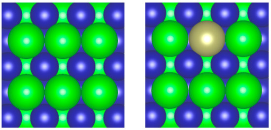
Figure 1.
Top view of ZrCo(110) (left) and Hf-doped ZrCo(110) (right) surface (green, blue and brown ball represent Zr, Co and Hf atom, respectively).

Table 1.
Energetics of H and CO adsorption on pure the ZrCo(110).
Table 2.
Energetics of H and CO adsorption on the doped ZrCo(110).
3.1. Energetics and Structures of H and CO Adsorption on Pure and Doped ZrCo(110) Surface
3.1.1. On the Pure ZrCo(110) Surface
In order to study the co-adsorption behavior of H and CO on the ZrCo(110) surface, the individual adsorption was studied first. Using the optimized ZrCo(110) surface as the substrate, H atoms and CO molecule are placed on the surface for adsorption behavior investigation. Due to the simple adsorption configurations of H, only the structures of CO adsorption on the pure ZrCo(110) surface with b1 and b2 direction are depicted, as shown in Figure 2 and Figure 3, respectively, where the green, blue, red and dark brown ball represent the Zr, Co, O and C atom, respectively. They are all located at different local chemical environments of the surface atom. We note that the orientation of the CO molecule on the ZrCo surface is different from the H adsorption structures. The conspicuous feature is the presence of a tilted angle between the C-O bond and normal direction of the ZrCo(110) plane and along the normal direction with the C atom being below. Since all configurations in present calculations are optimized without any symmetry constraints, the tilting of CO reflects the attractive interaction of CO molecule with the ZrCo surface. Additionally, the structure is also closely related to adsorption energy. For example, for the TopCo structure, the CO is 1.729 Å above the surface and the adsorption energy is −1.935 eV, while it increases to −1.773 eV when the distance decreases to 1.923 Å for the BridgeCoCo site.
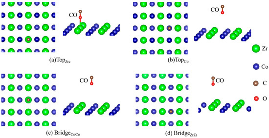
Figure 2.
Structures of CO adsorption on the pure ZrCo(110) surface (b1), where the green, blue, red and dark brown ball represent the Zr, Co, O and C atom, respectively.
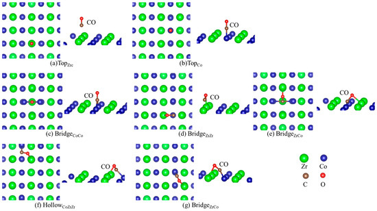
Figure 3.
Structures of CO adsorption on the pure ZrCo(110) surface (b2).
Table 1 lists the adsorption energy of H and CO on the pure ZrCo surface individually. As can be seen from the data in Table 1, the most stable adsorption site of H is HollowZrCoCo, followed by the BridgeCoCo, BridgeZrZr, TopCo and TopZr sites. In general, the absolute value of H adsorption energy is greater than the adsorption energy of CO, indicating that H adsorption is stronger than CO. The interaction between the CO and ZrCo surface is also strong, which was evidenced by experimental results [36]. In contrast, the C atom of CO is more likely to interact with the Co atom. Moreover, there are seven adsorption sites of CO (b2), which is more than those of H. And the adsorption energies of sites containing a Co atom, such as HollowZrCoCo, TopCo, HollowCoZrZr, BridgeZrCo and BridgeCoCo, are smaller than those of TopZr and BridgeZrZr. It is indicated that CO mainly reacts with Co [36], which catalyzes the decomposition of CO into graphite and CO2 and forms carbides of Co, accompanied by the generation of oxides such as ZrOx. However, the literature [51,52] elucidates that Co is an important active site for the hydrogen molecules’ dissociation in ZrCo alloys, so the reaction of CO and Co prevents the adsorption and further dissociation of H2 on the surface of the ZrCo alloy and the diffusion into the interior of the lattice.
3.1.2. On the Doped ZrCo(110) Surface
Table 2 lists the energetics of H and CO adsorption separately on the Hf-doped ZrCo(110), and the corresponding structures are shown in Figure 4 and Figure 5. It can be seen from the data in Table 2 that the adsorption strength of H is greater than that of CO after Hf doping. There are six stable adsorption sites, more than those on the pure surface. For the adsorption of CO (b2) on the doped surface, the TopCo sites are energetically most preferable. The adsorption of CO (b2) at the TopCo and BridgeCoCo sites (−1.958 eV and −1.954 eV) is stronger than at the TopHf and TopZr sites, respectively. Therefore, the subsequent stages of the co-adsorption were calculated only for CO (b2) at the TopCo and BridgeCoCo site. Additionally, Hf doping reduces the number of CO adsorption sites whether it is ‘b1’ or ‘b2’. There are only four stable adsorption sites for CO (b2) on the doped surface, while it is seven for the pure surface. Table 1 shows that the C atom of CO is more likely to interact with the surface atom characterized by the lower adsorption energies, which can also be seen from the data in Table 2. Therefore, the presence of Hf inhibits the formation of carbides to a certain extent, thereby improving the resistance to CO toxicity performance of ZrCo.
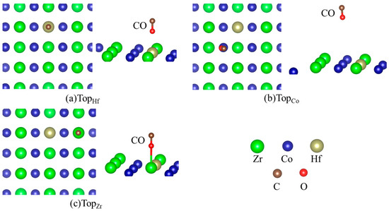
Figure 4.
Structures of CO adsorption on the doped ZrCo(110) surface (b1).
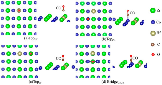
Figure 5.
Structures of CO adsorption on the doped ZrCo(110) surface (b2).
3.2. Co-Adsorption on the Pure and Doped Surfaces
As seen above, both H and CO adsorb strongly on the ZrCo(110) surface. For the hydrogen storage materials, CO can passivate the ZrCo surface and reduce the performance of storage and release. To study the effect of the CO on the H atom adsorption on the ZrCo surface, the CO and H atoms co-adsorbed on the ZrCo surface were calculated and analyzed. We selected the combination of the three most stable structures of H adsorbed on the ZrCo surface and the two most stable structures of CO adsorbed on the ZrCo surface to obtain the co-adsorption structure. In this scenario, the CO-precovered ZrCo(110) surface was the substrate for the adsorption of H atoms. The study shows that, after relaxation, there are three co-adsorption structures on the pure surface, namely HollowZrCoCo + HollowCoZrZr, TopCo(b2) + BridgeCoCo and TopCo(b2) + HollowCoZrZr. The most stable configuration is TopCo(b2) + HollowCoZrZr with an adsorption energy of −4.101 eV (shown in Table 3), and the structure is shown in Figure 6a. The energy of adsorption of H increases from −4.083 eV to −3.922 eV on a hollow site. The variance in adsorption energy may be due to the change in the surface atomic electronic structures resulting from the interaction with CO moclecule.
Table 3.
Energetics of H and CO co-adsorption on the pure ZrCo(110).
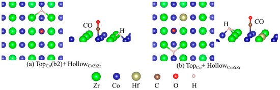
Figure 6.
The most stable structures of CO and H co-adsorption on the pure (a) and doped (b) ZrCo(110) surface: (a) TopCo(b2) + HollowCoZrZr and (b) TopCo + HollowCoZrZr, where the green, blue, brown, red, dark brown and light pink ball represent the Zr, Co, Hf, O, C and H atom, respectively.
For the doped surface, the configurations containing ‘BridgeCoCo(b2) + BridgeCoCo, BridgeCoCo(b2) + HollowZrCoHf, BridgeCoCo(b2) + HollowCoZrZr, TopCo + BridgeCoCo, TopCo + HollowZrCoHf and TopCo + HollowCoZrZr’ are stable after relaxation. Among them, the most stable structure is TopCo + HollowCoZrZr. The most stable structure of H and CO co-adsorption on the doped surfaces is shown in Figure 6b, where the green, blue, brown, red, dark brown and light pink ball represent the Zr, Co, Hf, O, C and H atom, respectively. The Hf dopant makes the height of the H atoms decrease from 1.220 Å to 0.968 Å, enhancing interaction with the surface. On the other hand, from the adsorption energy results, one can see that the hydrogen adsorption energy at the clean surface is −4.083 eV without doping the Hf. The H adsorption on CO-precovered surfaces is weakened by the presence of CO. After doping with Hf, ΔEad,H takes a value of −4.094 eV (shown in Table 4), which approaches the value for the pure clean surface. Even with a CO molecule on the surface, a Hf atom decorating the surface could improve the hydrogen adsorption energy to the level of the clean surface.
Table 4.
Energetics of H and CO co-adsorption on the doped ZrCo(110).
3.3. Electronic Structures
It is of interest to understand the effects of Hf atoms on the resistance to CO toxicity of the ZrCo surface from the view of the electronic structure, and the electronic structures of single H and CO adsorption on the pure and doped surface are calculated and compared with each other, as is shown in Figure 7.
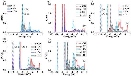
Figure 7.
The projected DOS of different adsorption structures on the pure and doped surface: (a) H on ZrCo surface (HollowCoZrZr), (b) CO on the ZrCo(HollowCoZrZr), (c) H and CO on the ZrCo(TopCo-HollowCoZrZr), (d) CO on the doped ZrCo(TopCo (b2)), and (e) H and CO on the doped ZrCo(TopCo (b2)-HollowCoZrZr)).
H or CO adsorption. Figure 7a presents the partial density of states (PDOS) for the system of the H atom adsorbed on the pure ZrCo surface. It is obvious that the peak at −6.0 eV is the H 1 s orbital. The PDOS of the s of the Co atom is also around −6.0 eV when the hydrogen atom is adsorbed, clarifying a strong interaction between the H and Co atoms, which coincides with the analyses of adsorption energies. For the CO adsorption on the ZrCo surface, one can see that the p states of CO give rise to an anti-bonding at about 1.0 eV above the Fermi level (Figure 7b). The overlap between the PDOS of CO and Co happens mainly at about −10.9 eV, −7.8 eV and −6.8 eV, showing the strong interaction of CO and the Co atom, verifying the results of adsorption energy. Additionally, the overlap between CO and Co atoms only happens at about −6.8 eV for the doped system, as shown in Figure 7d. These results hint that Hf doping can make the interaction between CO and surface atoms weaken, coinciding with the adsorption sites.
H and CO co-adsorption. To deepen the understanding of the effect of Hf doping on CO toxicity, the PDOS of H and CO co-adsorption on the pure and doped surface are analyzed, as shown in Figure 7c,e. The anti-bonding 2π* produced by the p state of CO is slightly modified in comparison with that presented in Figure 7b, which is shown by the variance in the peak of the CO-p state. The peak of the lowest energy is located at about 1.0 eV for the H and CO co-adsorption. There is an interaction of the Co s orbital with the CO s orbital revealed by the appearance of a shoulder at the peak around −6.7 eV and at −9.9 eV, as shown in Figure 7c. The interaction between the s orbital of Co and s orbital of H is weak compared with the CO s orbital for the case of H and CO co-adsorption on the pure surface, while it is obviously in the range of [−5 eV, −7 eV] for H on the ZrCo surface, as shown in Figure 7a. The result indirectly indicates that CO inhibits the interaction between H and Co. On the other hand, the distance between H and CO increases from 1.151 Å to 3.443 Å after optimization during the process of structural relaxation, indicating that there is a large repulsion interaction between them. One can see from Figure 7c that there is almost no interaction between the s orbital of H and the s orbital of Co, while on the doped surface of pre-adsorbed CO (Figure 7e), the s orbital of H overlapped greatly with the s orbital of Co in the vicinity of −6.5 eV to −2.3 eV. The results show that Hf doping inhibits the CO toxicity on the interaction between H and surface. In other words, doping Hf could improve the resistance to CO toxicity on a ZrCo surface, which is conducive to the adsorption of H and then beneficial to the performance of the storage of hydrogen.
4. Conclusions
A series of density functional theory calculations have been performed to investigate the adsorption of H and CO and the co-adsorption of both species on the pure and doped ZrCo(110) surfaces, comparing the effect of the Hf dopant on the CO toxicity of the ZrCo surface with the CO-free surface. The main conclusions are as follows.
- It can be understood that the CO occupies the adsorption site of H and therefore prevents the adsorption and diffusion into the interior of the lattice.
- Fortunately and interestingly, the presence of Hf reduces the number of adsorption sites of CO and inhibits the formation of carbides to a certain extent.
- Moreover, the PDOS result shows that Hf doping inhibits the CO toxicity on the interaction between H and the surface atom, which is indicated by the great overlap between the s orbital of H and the s orbital of Co on the doped surface.
The DFT data and analysis thus demonstrate that the ability of the resistance to CO toxicity of the surface doped by Hf is more favorable than that of the clean surface, providing an example for reducing the CO toxicity at the ZrCo surface for hydrogen adsorption. However, the present results lack experimental validation. In the next work, further experimental validation by IR, Raman, XPS and EELS will be processed. The adsorption configurations of H/CO on the ZrCo surface can be investigated with infrared and Raman spectroscopy by measuring vibrational frequencies of the species on the surface. With the XPS and EELS techniques, the possible types of bonding can be explored further.
Author Contributions
Conceptualization, X.K., D.O.K. and L.W.; methodology, X.K.; software, X.K.; validation, R.P., D.O.K. and L.W.; formal analysis, X.K.; investigation, X.K.; resources, R.P.; data curation, X.K. and R.P.; writing—original draft preparation, X.K.; writing—review and editing, X.K., R.P., D.O.K. and L.W.; visualization, X.K. and R.P.; supervision, D.O.K. and L.W.; project administration, L.W.; funding acquisition, L.W. All authors have read and agreed to the published version of the manuscript.
Funding
This research was funded by National Key Research and Development Program of China (No. 2022YFB190122), China Postdoc-toral Science Foundation Program (No. 2021M693034), National Natural Science Foundation of China (No. 12004055), Natural Science Foundation of Sichuan Province (No. 2023NSFSC0404), the Leading and Innovation Program of China National Nuclear Corporation (No. JJXM-JTLC-2021-06) and the International Science and Technology Cooperation Project of Sichuan Province (No. 2022YFH0043).
Data Availability Statement
The data presented in this study are available in article.
Conflicts of Interest
The authors declare no conflict of interest.
References
- Xu, Y.; Deng, Y.; Liu, W.; Zhao, X.; Xu, J.; Yuan, Z. Research progress of hydrogen energy and metal hydrogen storage materials. Sustain. Energy Technol. Assess. 2023, 55, 102974. [Google Scholar] [CrossRef]
- Nagar, R.; Srivastava, S.; Hudson, S.L.; Amaya, S.L.; Tanna, A.; Sharma, M.; Achayalingam, R.; Sonkaria, S.; Khare, V.; Srinivasan, S.S. Recent developments in state-of-the-art hydrogen energy technologies–review of hydrogen storage materials. Sol. Compass 2023, 5, 100033. [Google Scholar] [CrossRef]
- Mingxing, W.; Yijin, L.; Xiaofei, X.; Zhao, Z.; Tong, L. (TiVZrNb)83Cr17 high-entropy alloy as catalyst for hydrogen storage in MgH2. Chem. Eng. J. 2023, 476, 146525. [Google Scholar]
- Mac Dowell, N.; Sunny, N.; Brandon, N.; Herzog, H.; Ku, A.Y.; Maas, W.; Ramirez, A.; Reiner, D.M.; Sant, G.N.; Shah, N. The hydrogen economy: A pragmatic path forward. Joule 2021, 5, 2524–2529. [Google Scholar] [CrossRef]
- Leonardo, G.; Antonio, A.; Alessandro, C.; Nicola, P. Materials for Hydrogen Storage and Transport: Implications for Risk-Based Inspection. Key Eng. Mater. 2023, 6954, 221–230. [Google Scholar]
- Nibedita, N.; Subhendu, C.; Sumit, S.; Abhishek, S.; Singh, Y.A.; Tabish, A. A graphene-based material for green sustainable energy technology for hydrogen storage. Environ. Sci. Pollut. Res. Int. 2023. [Google Scholar] [CrossRef]
- Evans, H.A.; Yildirim, T.; Peng, P.; Cheng, Y.; Deng, Z.; Zhang, Q.; Mullangi, D.; Zhao, D.; Canepa, P.; Breunig, H.M.; et al. Hydrogen Storage with Aluminum Formate, ALF: Experimental, Computational, and Technoeconomic Studies. J. Am. Chem. Soc. 2023, 145, 22150–22157. [Google Scholar] [CrossRef]
- Sahar, Z.-A.; Hasanzadeh, E.M.; Marjerrison, C.A.; John, G.; Mahdi, B. Enhanced electrochemical hydrogen storage performance of lanthanum zirconium oxide ceramic microstructures synthesized by a simple approach. Ceram. Int. 2023, 49 Pt 23, 37415–37422. [Google Scholar]
- Ruyue, L.; Hang, L.; Xiangyu, P.; Jiajin, Z.; Wenfeng, W.; Yuan, L.; Ning, X.; Qiuming, P.; Shumin, H.; Lu, Z. Improvement on cyclic stability of AB4-type La–Mg–Ni-based hydrogen storage alloys via merging Y element for nickel-metal hydride batteries. Int. J. Hydrogen Energ. 2023, 48, 32849–32859. [Google Scholar]
- Zhang, T.B.; Yang, X.W.; Li, J.S.; Hu, R.; Xue, X.Y.; Fu, H.Z. On the poisoning effect of O2 and N2 for the Zr0.9Ti0.1V2 hydrogen storage alloy. J. Power Sources 2011, 202, 217–224. [Google Scholar] [CrossRef]
- Beom Park, K.; Fadonougbo, J.O.; Park, C.S.; Lee, J.H.; Na, T.W.; Kang, H.S.; Ko, W.S.; Park, H.K. Effect of Fe substitution on first hydrogenation kinetics of TiFe-based hydrogen storage alloys after air exposure. Int. J. Hydrogen Energy 2021, 46, 30780–30789. [Google Scholar] [CrossRef]
- Fonseca, S.; Maia, G.; Pinto, L. Hydrogen adsorption in the presence of coadsorbed CO on Pd (111). Electrochem. Commun. 2018, 93, 100–103. [Google Scholar] [CrossRef]
- Hefnawy, M.A.; Fadlallah, S.A.; El-Sherif, R.M.; Medany, S.S. Systematic DFT studies of CO-Tolerance and CO oxidation on Cu-doped Ni surfaces. J. Mol. Graph. Model. 2023, 118, 108343. [Google Scholar] [CrossRef] [PubMed]
- Curulla-Ferre, D.; Govender, A.; Bromfield, T.C.; Niemantsverdriet, J. A DFT study of the adsorption and dissociation of CO on sulfur-precovered Fe (100). J. Phys. Chem. B 2006, 110, 13897–13904. [Google Scholar] [CrossRef] [PubMed]
- Svenum, I.-H.; Herron, J.A.; Mavrikakis, M.; Venvik, H.J. Pd3Ag (111) as a model system for hydrogen separation membranes: Combined effects of CO adsorption and surface termination on the activation of molecular hydrogen. Top. Catal. 2020, 63, 750–761. [Google Scholar] [CrossRef]
- Easa, J.; Yan, C.; Schneider, W.F.; O’Brien, C.P. CO and C3H6 poisoning of hydrogen permeation across Pd77Ag23 alloy membranes: A comparative study with pure palladium. Chem. Eng. J. 2022, 430, 133080. [Google Scholar] [CrossRef]
- Song, C.; Ge, Q.; Wang, L. DFT studies of Pt/Au bimetallic clusters and their interactions with the CO molecule. J. Phys. Chem. B 2005, 109, 22341–22350. [Google Scholar] [CrossRef] [PubMed]
- Gonzalez, S.; Illas, F. CO adsorption on monometallic Pd, Rh, Cu and bimetallic PdCu and RhCu monolayers supported on Ru (0001). Surf. Sci. 2005, 598, 144–155. [Google Scholar] [CrossRef]
- Zhou, Y.; Xie, Z.; Jiang, J.; Wang, J.; Song, X.; He, Q.; Ding, W.; Wei, Z. Lattice-confined Ru clusters with high CO tolerance and activity for the hydrogen oxidation reaction. Nat. Catal. 2020, 3, 454–462. [Google Scholar] [CrossRef]
- Eichler, A. Chemical characterization of a zirconia-supported Pt cluster. Phys. Rev. B 2005, 71, 125418. [Google Scholar] [CrossRef]
- Yangkun, W.; Ken, M.; Satoshi, K.; Toshiaki, N.; Fumitaka, M. Hydrogen Storage Mechanism by Gas-Phase Vanadium Cluster Cations Revealed by Thermal Desorption Spectrometry. J. Phys. Chem. A 2023, 127, 8821–8827. [Google Scholar]
- Ruoqi, Z.; Delu, G.; Yixuan, L.; Dunyou, W. First principle study of enhanced CO adsorption on divacancy graphene-supported TM7 (TM=Fe, Co, Ni, Cu, Ag, and Au) clusters. Chem. Phys. 2024, 576, 112089. [Google Scholar]
- Li, B.; Wang, X.F.; Wang, W.Y.; Liu, C.F.; He, L.C.; Luo, M.F.; Chen, J. Identifying the surface active sites of FeOx-modified Pt/Nb2O5 catalysts in CO and propane oxidation. Appl. Catal. A-Gen. 2023, 649, 118960. [Google Scholar] [CrossRef]
- Liu, L.; McAllister, B.; Ye, H.; Hu, P. Identifying an O2 supply pathway in CO oxidation on Au/TiO2 (110): A density functional theory study on the intrinsic role of water. J. Am. Chem. Soc. 2006, 128, 4017–4022. [Google Scholar] [CrossRef] [PubMed]
- Molina, L.; Hammer, B. Theoretical study of CO oxidation on Au nanoparticles supported by MgO (100). Phys. Rev. B 2004, 69, 155424. [Google Scholar] [CrossRef]
- Sandrock, G.; Goodell, P. Surface poisoning of LaNi5, FeTi and (Fe, Mn) Ti by O2, CO and H2O. J. Less Common Met. 1980, 73, 161–168. [Google Scholar] [CrossRef]
- Tanaka, H.; Kuriyama, N.; Ichikawa, S.; Senoh, H.; Naka, N.; Aihara, K.; Itoh, H.; Tsukahara, M. Degrading mechanism on hydrogen absorbing-desorbing cycle durability of V-and Ti-Cr-based BCC-type solid solutions. Mater. Sci. Forum 2005, 475–479, 2481–2484. [Google Scholar] [CrossRef]
- Han, S.; Zhang, X.; Shi, S.; Tanaka, H.; Kuriyama, N.; Taoka, N.; Aihara, K.; Xu, Q. Experimental and theoretical investigation of the cycle durability against CO and degradation mechanism of the LaNi5 hydrogen storage alloy. J. Alloys Compd. 2007, 446, 208–211. [Google Scholar] [CrossRef]
- Thiébaut, S.; Douilly, M.; Contreras, S.; Limacher, B.; Paul-Boncour, V.; Décamps, B.; Percheron-Guégan, A. 3He retention in LaNi5 and Pd tritides: Dependence on stoichiometry, 3He distribution and aging effects. J. Alloys Compd. 2007, 446, 660–669. [Google Scholar] [CrossRef]
- Devillers, M.; Sirch, M.; Bredendiek-Kämper, S.; Penzhorn, R. Characterization of the zirconium-cobalt (ZrCo)-hydrogen system in view of its use for tritium storage. Chem. Mater. 1990, 2, 255–262. [Google Scholar] [CrossRef]
- Longhurst, G. Pyrophoricity of tritium-storage bed materials. Fusion Technol. 1988, 14, 750–755. [Google Scholar] [CrossRef]
- Wang, Q.; Kong, X.; Yu, Y.; Song, J.; Wu, L. Influence of the Fe-doping on hydrogen behavior on the ZrCo surface. Int. J. Hydrogen Energy 2021, 46, 33877–33888. [Google Scholar] [CrossRef]
- Penzhorn, R.-D.; Sirch, M. Evaluation of ZrCo and other getters for tritium handling and storage. J. Nucl. Mater. 1990, 170, 217–231. [Google Scholar] [CrossRef]
- Xianggang, K.; You, Y.; Yanhong, S.; Jiangfeng, S. Effect of Hf doping on He behavior in tritium storage material ZrCo. Phys. Chem. Chem. Phys. 2021, 23, 18686–18693. [Google Scholar]
- Qingqing, W.; Xianggang, K.; You, Y.; Huilei, H.; Ge, S.; Guanghui, Z.; Yougen, Y.; Tao, G. Effect of multiple Ti doping on helium behavior in ZrCo. J. Nucl. Mater. 2021, 551, 152955. [Google Scholar]
- Glasbrenner, H.; Klewe-Nebenius, H.; Bruns, M.; Pfennig, G.; Penzhorn, R.D.; Joachim Ache, H. Surface analytical investigation of the tritium getter ZrCo after exposure to various gases. Microchim. Acta 1992, 107, 207–217. [Google Scholar] [CrossRef]
- Hualing, L.; Shumao, W.; Lijun, J.; Zhang, L.; Xiaopeng, L.; Zhinian, L. Preparation and research on poisoning resistant Zr-Co based hydrogen storage alloys. Rare Metals 2008, 27, 367–370. [Google Scholar]
- Wang, Q.; Kong, X.; Han, H.; Sang, G.; Zhang, G.; Gao, T. Effect of doping Hf on the hydrogen dissociation and diffusion mechanism on the ZrCo(110) surface. Appl. Surf. Sci. 2019, 483, 383–390. [Google Scholar] [CrossRef]
- Wang, Q.; Kong, X.; Han, H.; Sang, G.; Zhang, G.; Yi, Y.; Gao, T. Influence of Ti on the dissolution and migration of He in ZrCo based on first principles investigation. Phys. Chem. Chem. Phys. 2019, 21, 14692–14700. [Google Scholar] [CrossRef]
- Wang, Q.; Yu, Y.; Sang, G.; Yi, Y.-G.; Gao, T. Effect of doping Ti on the vacancy trapping mechanism for the helium in ZrCo from first principles. Phys. Chem. Chem. Phys. 2019, 21, 20909–20918. [Google Scholar] [CrossRef]
- Li, J.; Li, D.; Lang, W.; Wu, F.; Wang, G. Surface properties and poisoning of ZrCr2−xFex. Min. Metall. Eng. 1994, 14, 61–63. [Google Scholar]
- Wang, L.; Ding, J.; Huang, X.; Song, K.; Liu, B.; Zeng, X. Influence of Ti/Hf doping on hydrogen storage performance and mechanical properties of ZrCo compounds: A first principle study. Int. J. Hydrogen Energy 2018, 43, 13328–13338. [Google Scholar] [CrossRef]
- Kresse, G.; Furthmüller, J. Efficient iterative schemes for ab initio total-energy calculations using a plane-wave basis set. Phys. Rev. B 1996, 54, 11169. [Google Scholar] [CrossRef]
- Kresse, G.; Furthmüller, J. Efficiency of ab-initio total energy calculations for metals and semiconductors using a plane-wave basis set. Comp. Mater. Sci. 1996, 6, 15–50. [Google Scholar] [CrossRef]
- Perdew, J.P.; Burke, K.; Ernzerhof, M. Generalized gradient approximation made simple. Phys. Rev. Lett. 1996, 77, 3865. [Google Scholar] [CrossRef]
- Monkhorst, H.J.; Pack, J.D. Special points for Brillouin-zone integrations. Phys. Rev. B 1976, 13, 5188. [Google Scholar] [CrossRef]
- Harris, I.R.; Hussain, D.; Barraclough, K.G. The constitution of the binary equiatomic alloys of Zr with Fe, Co and Ni. Scr. Metall. 1970, 4, 305–307. [Google Scholar] [CrossRef]
- Ivanov, O.; Adamova, A.; Tararaeva, E.; Tregubov, I. Structure of Zirconium Alloys; Struktura Splavov Tsirkoniya; U.S. Department of Energy Office of Scientific and Technical Information: Oak Ridge, TN, USA, 1973.
- Nan, H.; Meng, H.; Evangelista, F.A. CO Inversion on a NaCl(100) Surface: A Multireference Quantum Embedding Study. J. Phys. Chem. A 2023, 127, 1975–1987. [Google Scholar]
- Wang, Q.; Kong, X.; Han, H.; Sang, G.; Zhang, G.; Gao, T. The performance of adsorption, dissociation and diffusion mechanism of hydrogen on the Ti-doped ZrCo(110) surface. Phys. Chem. Chem. Phys. 2019, 21, 12597–12605. [Google Scholar] [CrossRef]
- Penzhorn, R.-D.; Devillers, M.; Sirch, M. Storage of tritium in ZrCo alloy: Effect of pre-exposure to impurities relevant to the fusion fuel cycle. J. Nucl. Mater. 1991, 179, 863–866. [Google Scholar] [CrossRef]
- Devillers, M.; Sirch, M.; Penzhorn, R.-D. Hydrogen isotopes in pure and nitrided ZrCo. Z. Phys. Chem. 1989, 164, 1355–1360. [Google Scholar] [CrossRef]
Disclaimer/Publisher’s Note: The statements, opinions and data contained in all publications are solely those of the individual author(s) and contributor(s) and not of MDPI and/or the editor(s). MDPI and/or the editor(s) disclaim responsibility for any injury to people or property resulting from any ideas, methods, instructions or products referred to in the content. |
© 2023 by the authors. Licensee MDPI, Basel, Switzerland. This article is an open access article distributed under the terms and conditions of the Creative Commons Attribution (CC BY) license (https://creativecommons.org/licenses/by/4.0/).