Abstract
During powder-bed fusion (PBF), the irradiated material causes undesirable thermal stresses while experiencing large temperature oscillations over a rapid period. This requires the components produced by this technique to undergo thermal treatment. The characteristics of additively manufactured materials, which are rapid heating and cooling, do not accept conventional methods, such as thermal treatment, that alleviate stress for the removal of thermal stresses. In this research, the thermal treatment of age hardening is explored, in which AlSi10Mg is subjected to lower temperatures for longer periods of time. Other samples were thermally treated at 300 °C and 400 °C for various hours and quenched in ice water. This is conducted to identify the acceptable temperature and conditions that will improve the properties after thermal treatment without jeopardising other properties of the material and to investigate the effects of the thermal treatment profiles on the microstructural and mechanical characteristics of the AlSi10Mg samples.
1. Introduction
Compared to conventional production methods, the powder-bed fusion method (PBF) of additive manufacturing offers various benefits, such as excellent material use proficiency, near-net shape production, decrease in production steps, and an extraordinary level of flexibility and complexity of parts [1,2]. PBF can also process materials with high melting points, which are relatively hard materials. However, the exceptional characteristics of PBF, such as the rapid heating and cooling process, cause some difficulties [3]. The composite thermal narratives, extreme density of the defects and extreme degree of surface abnormalities produced by the occurrence of tensile residual stresses, and inadequate ductility can negatively influence the integrity of the structural components of PBF built materials. Mechanical and thermal post-treatment have been used to try to relieve these residual stresses [4]. Most thermal post-treatment investigations for additive-made materials have been based on the implementation of reputable conservative thermal treatment techniques generally applied on the cast materials of comparable compositions. However, in previous studies by Mfusi et al. [5], it was determined that the thermal treatment profile has a negative impact on the strength and hardness of additively manufactured samples. Therefore, it is crucial to create unique thermal treatment profiles that are suitable for AM samples to fully utilise the benefits of technology in the creation of components for industrial applications [6].
Due to its castability and weldability, AlSi10Mg is generally known to be an age-hardenable alloy with good mechanical characteristics due to its near-eutectic composition [7]. AlSi10Mg has been extensively studied in the conventional and additive manufacturing arenas [8]. As a result of its great castability, reduced temperature, and reduced contraction, AlSi10Mg has been one of the eutectic and hypoeutectic Al–Si alloys chosen by various investigators as the testing material for powder bed AM. This is due to the recognition of significant factors influencing the mechanical characteristics of Al–Si alloys, which are the amount of sophisticated eutectic silicon morphology [9]. However, the continuous evolution of the application of additively manufactured components (AM) within the aerospace and automotive industries considers it necessary to further explore the performance of the material in different environments [10]. Additive manufacturing has not yet discovered an appropriate post-build thermal treatment for most of its materials. The conventional method of thermal treating AlSi10Mg, which is a stress reliever, does not produce substantial results. Consequently, mechanical properties are compromised, such as when ductility is achieved, strength is compromised, and vice versa [11].
The morphology and size of eutectic silicon during thermal treatment, when agglomerated, has been found to be the most significant microstructural consequence that affects the mechanical characteristics of AlSi10Mg [5,12]. In this work, it was assumed that, because aluminium is a soft material, its atoms can be excited at lower temperatures but with time. The aim was to attempt to excite and diffuse aluminium in the matrix rather than silicon at the boundaries in order to reduce the residual stresses in the material, thus enhancing the mechanical properties thereof. This is because aluminium has a lower melting point than silicon. Residual stresses are stresses that form in a material even if no external forces are applied to the material and can be induced by a number of factors [13]. The reduction in residual stresses built up that are formed as a result of the rapid heating and cooling characteristics of AM processes, especially in SLM, is the most imperative part of this investigation to pursue the production of components with significantly outstanding microstructural, mechanical, and integrity of these properties. The as-built AlSi10Mg already consists of an almost 100% relative density; therefore, the idea of this work to achieve its objective is not to alter the microstructure in any way but to remove the residual only.
2. Experimental Procedure
2.1. Specimen Production
The 10 cm high tensile as well as the 25 × 25 × 25 mm3 cubes for residual stress measurement samples were produced by SLM Solutions M280 with fixed parameters of 150 W power, 1000 mm/s scan speed, 50 μm hatch spacing, and 50 μm powder layer thickness. The samples were built vertically (Z-direction).
2.2. Heat Treatment Profiles
Thermal treatment trials were carried out as follows: (1) the samples were thermally treated in a Muffle furnace at 50 °C for 5, 10, and 15 h as well as at 100 °C for 4, 8, and 12 h, respectively. (2) The other samples were also thermally treated in a Muffle furnace at 300 °C for 2.5 and 3 h and others at 400 °C for 2.5 and 3 h, respectively, and then quenched in ice water. The samples were then studied separately for differences relative to time and temperature. Aged hardened tensile samples were removed from the furnace and air-cooled at room temperature. The quenching samples were quenched in ice water of 0 °C. Age-hardening thermal treatment profiles were created with the intention of diffusing the aluminium matrix only at lower temperatures while avoiding the boundaries of eutectic silicon when attempting to reduce residual stresses. The ice-water quenching profile was created with the intention to freeze the diffused aluminium matrix and prevent the coarsening of the eutectic silicon during room temperature cooling that happens when stress is relieved. The thermal treatment profiles are not from standard conventional methods.
2.3. Characterisation Technique
Tensile testing was performed on all samples using the 20 kN Zwick/Roell Tensile Tester applying standard ASTM E8/E8M-16a. Before microstructural characterisation with an Olympus optical microscope, samples were sectioned, mounted, polished, and etched with Keller’s reagent for 20 s. Hardness testing on the mounted samples was performed on the Zwick Micro/Macro Vickers hardness tester with a load of 300 gf. Fractographic testing was performed on the JEOL JSM 6010 Plus/LA, analytical scanning electron microscope (SEM). Residual stress measurements were carried out on the AUTOMATE II micro-area X-ray diffraction (XRD) system at 0°, 45°, and 90° angles (sample nature, Bragg 139, FCC-311).
3. Results and Discussion
3.1. Measurements of Hardness
Figure 1 shows diagrams of the hardness results for the samples age-hardened at 50 °C and 100 °C for various long hours, followed by the samples thermally treated at 300 °C for 2.5 and 3 h, as well as at 400 °C for 2.5 and 3 h and quenched in ice water.
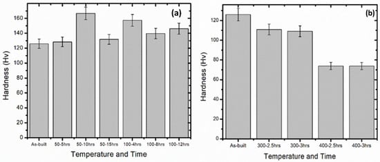
Figure 1.
Hardness of the thermal treatment of the samples age-hardened at (a) 50 °C and 100 °C and (b) ice-water quenched.
The results of the hardness test illustrate that thermal treatment at 50 °C for 5 h and 15 h shows a slight increase in hardness compared to the AlSi10Mg, which was 126 ± 0.564 Hv [1]. The hardness of the samples treated for 10 h increased significantly by 40 Hv. However, all results demonstrate an improvement. In the microstructure discussion, the literature has proven that precipitation of the not so often visible Mg2Si is the cause of the increase in the hardness of the samples as long as there is no expulsion of silicon particles from the eutectic boundaries, which also results in a change in microstructure [14,15,16].
Figure 1b demonstrates a drastic increase in hardness for samples that age-hardened at 100 °C. Hardness is a very important part of the mechanical characteristics of a material. It is one of the main reasons why this investigation was carried out to improve the hardness of the material as part of the material’s ability to resist plastic deformation [12]. In these samples, a significant increase in hardness of 20, 10, and 14% is observed, respectively, after age-hardening. Friend and Luxton proved that the increase in hardness during long-hour age-hardening confirms the stimulation of the matrix characteristics, which corresponds to the fibres and matrix hardness by what they called the ‘modified rule of mixtures’ relationship. The change in hardness of the alloy is related to the change in hardness of the matrix by a factor equal to the volume of the matrix fraction [17]. This was the exact objective of this investigation to temper with the aluminium matrix in order to reduce the residual stresses rather than the eutectic silicon boundaries.
Ice-water-quenched samples demonstrate a reduction in hardness compared to built-in 126 Hv but it was better than the stress-relieving thermal treatment of 48 Hv [5]. Between these samples, it is observed that the samples thermally treated at 300 °C demonstrate better hardness than those thermally treated at 400 °C. As established by microstructure, it is observed in the hardness results that the more silicon disintegrates and agglomerates in the aluminium matrix, the more the samples soften with time and/or temperature [12].
3.2. Microstructural Analysis
3.2.1. Optical Microscope (OM) and Scanning Electron Microscope (SEM) for Age Hardening
Figure 2, Figure 3, Figure 4 and Figure 5 show the microstructures of the OM and SEM for the samples that age-hardened at 50 °C for 5, 10, and 15 h, respectively. The results of the optical microscope of the samples were thermally treated at a temperature of 50 °C for 5 h, 10 h, and 15 h, as observed in Figure 4. A few pores are observed in Figure 2 denoted by the yellow arrow. The common laser tracks and the eutectic silicon surrounding the limits of the aluminium matrix are still visible in all samples [1,10,18]. Images (a, b, and c) are the longitudinal views while (d, e, and f) are the sectional views in both the OM and SEM micrographs, respectively. This microstructure is understood to influence the mechanical characteristics of the material optimistically [8]. According to Fiocchi [8], the microstructures have undergone precipitation of Mg2Si, which is recognised to be too small to be distinguished in OM. The presence of at least 0.5% of Mg in the AlSi10Mg alloy causes the establishment of a precipitation of magnesium silicide that is hardly seen in the SLM built relative to rich silicon, as always tested as a result of the high solidification characteristic of the manufacture of distinctive powder-bed fusion additives. However, Mg2Si, which is needle-shaped, precipitates into the microstructure after thermal treatment, helping to strengthen the mechanical characteristics of the alloy [4,19].
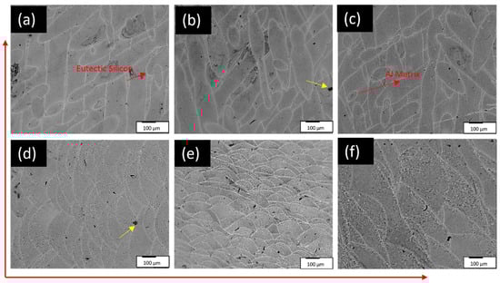
Figure 2.
OM samples of 10× magnification: (a,d) 50 °C–5 h, (b,e) 50 °C–10 h, (c,f) 50 °C–15 h. Yellow arrows mark the pores.
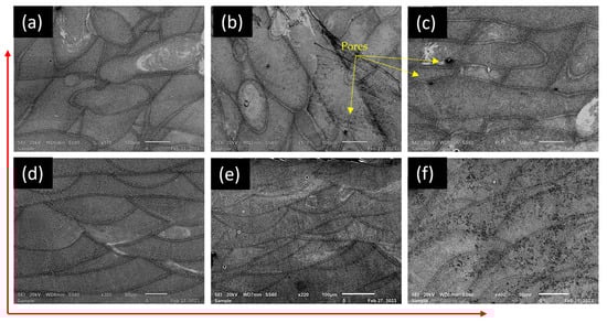
Figure 3.
SEM samples of different magnification: (a,d) 50 °C–5 h, (b,e) 50 °C–10 h, (c,f) 50 °C–15 h.
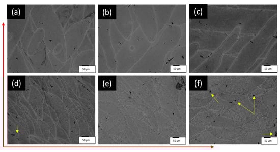
Figure 4.
OM samples of 20× magnification: (a,d) 100 °C–4 h, (b,e) 100 °C–8 h, (c,f) 100 °C–12 h.
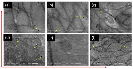
Figure 5.
SEM samples of different magnification: (a,d) 100 °C–4 h, (b,e) 100 °C–8 h, (c,f) 100 °C–12 h.
The microstructures show some pores, indicated by yellow arrows, that look like metallurgical pores that are small in size and spherical in shape and, according to [20,21], are a consequence of trapped gases within the molten pool.
The optical microscope and scanning electron microscope results of the samples were thermally treated at a temperature of 100 °C for 4 h, 8 h, and 12 h, as observed in Figure 4 and Figure 5, respectively. These samples do not show a change in microstructure after thermal treatment; fish-scale-like patterns are visible, which are the grain boundaries of the eutectic silicon surrounding the hair-like structures, which are the dendrites of the aluminium matrix [1,22,23]. The samples that were thermally treated for 8 h show fewer pores than those for 4 and 12 h. The role of silicon, among others, in AlSi10Mg is to reduce the melting point, so lower temperatures were selected in this study. The reduction in the melting point between the liquid and the eutectic temperature of AlSi10Mg is at least 83 °C with a thin solidification matrix. This decreases the energy essential to melt the metal powder and allows for a limited dimensional regulation to build complex shapes and projection assemblies [24,25].
3.2.2. Optical Microscope (OM) and Scanning Electron Microscope (SEM) of Ice-Water Quenching
Figure 6, Figure 7, Figure 8 and Figure 9 demonstrate the micrographs of the OM and SEM of the samples thermally treated at 300 °C and 400 °C for 2.5 and 3 h. The objective of quenching the samples was to suppress the precipitation of silicon expelled from the aluminium matrix that was observed in the stress relief thermal treatment. In Figure 8, it was observed that the microstructure of the OM sample appears to be swollen with multiple tiny holes. In the SEM micrographs, the distegrated silicon from the aluminium matrix is observed, as also seen from the stress-relieved samples, but, this time, with a lot of tiny microcracks, as though the samples experienced thermal shock when queched in the ice water.
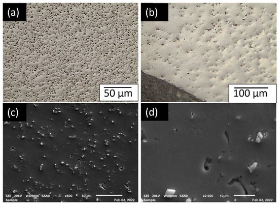
Figure 6.
OM (a,b) and SEM (c,d) images of the AlSi10Mg samples quenched at 300 °C for 2.5 h at various magnifications.
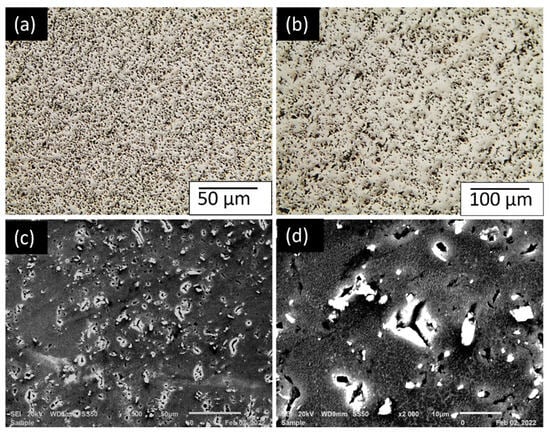
Figure 7.
OM (a,b) and SEM (c,d) images of the AlSi10Mg samples quenched at 300 °C for 3 h at various magnifications.
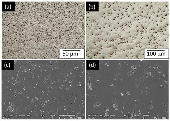
Figure 8.
OM (a,b) and SEM (c,d) images of the AlSi10Mg samples quenched at 400° C for 2.5 h at various magnifications.
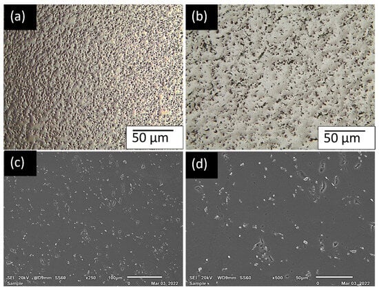
Figure 9.
OM (a,b) and SEM (c,d) images for AlSi10Mg samples quenched at 400 °C for 3 h at various magnifications.
These samples prove that, as soon as the silicon is expelled from the aluminium matrix, as the near-eutectic characteristic, which brings about the strength and density in the microstructure, the pursued microstructural and mechanical properties are lost. Figure 7 also illustrates the swollen microstructure with micro-pits in (a and b) as well as microcracks and tears in the SEM images of (c and d). The micro-pitting appears to be denser in these images compared to Figure 10. The magnitude and spread of eutectic silicon in the microstructure significantly alters the mechanical characteristics; for example, the area with larger acicular silicon atoms has reduced fatigue characteristics [25]. As agreed by Xiaohui et al. [26], the extreme temperature gradient does have a substantial consequence on structural integrity and the proper functioning of the constructed components; therefore, it is vital to work on the microstructure, residual stress, and mechanical characteristics of the material.

Figure 10.
Demonstrating the tensile strength of the thermal treatment of the samples age-hardened at 50 °C (a) and 100 °C (b) as well as ice-water-quenched samples (c).
The expelled silicon is not agglomerated, as was observed in the stress-relieved samples, but is scattered on the surface of the aluminium matrix, which could be the cause of the difference in hardness. Figure 7 shows no difference in the micro-pitting and swollen OM microstructure, as well as the cracked and torn SEM microstructure. Modification of silicon atoms in aluminium–silicon alloys is observed to be the most significant influence on improving their mechanical characteristics [25]. The loss of solution at the heterogeneous nucleation sites is generally what has been attributed to quench sensitivity in Al–Mg–Si alloys. It was proven to correlate with the degree of supersaturation of the vacancies once cooled [27].
In these samples, it is observed that the longer the period of thermal treatment, the denser the microstructural swelling and micro-pits. Figure 8 shows a denser bulged microstructure than that of 300 °C at 3 h, which is Figure 7. The expelled silicon also seems to be a little closer together in the aluminium matrix. Alghamdi and Fiocchi [8,28] found that exposure of AlSi10Mg to higher temperatures causes eutectic silicon in the intercellular system to experience disintegration, spheroidisation, and coarsening of morphological progressions with time and/or temperature. The extreme part of this morphological progression was observed in stress relief [5]. The spheroidisation and coarsening of silicon is what suffers from the hardness characteristic of AlSi10Mg.
3.3. Tensile Strength
Figure 10 shows graphs that demonstrate the tensile strength of the sample thermally treated by age-hardening at 50 °C and 100 °C for various long hours, as well as the quenched samples.
The stress at yield of all the samples age-hardened at 50 °C shows that they exceeded the values of the tensile strength of the as-built AlSi10Mg samples, which was 243.72 MPa. The UTS of the aged, hardened samples for 5 and 10 h also exceeded that of the built samples, which was 473.18 MPa, and the 15 h samples were significantly below but comparatively above that of the cast samples, which was 335 MPa. The Young’s modulus, though, of the as-built samples, which was 70.77 GPa, exceeds all the samples age-hardened at 50 °C. This means that these age-hardened samples are more elastic than the as-built samples, which is another highly pursued characteristic. The elongation of the samples as they age-hardened for 5 and 15 h decreased, and the 10 h samples remained the same as that as-built, which was 6.8% [15]. The observation here is interesting because the hardness improved drastically without compromising the elongation. In fact, samples aged hardened for 10 h have shown tremendous strength, with a UTS of 480 MPa and a stress at yield of 293 MPa.
The stress in the yield of the aged hardened samples at 100 °C is the same and higher than that of the as-built samples by approximately 3% and the Young’s modulus is approximately 12% lower than that of the as-built samples, demonstrating that the elasticity of the samples after thermal treatment of age-hardening the UTS shows no significant variation from that of the as-built samples, while the elongation has a significant drop of approximately 1%. Welsch et al. confirms that the increase in yield strength and modulus after age-hardening is due to the formation of precipitates within the primary α grains [29], which, in this case, is Mg2Si. Banerjee discovered that silicon is responsible for the nucleation of the precipitates during the thermal treatment of age-hardening in aluminium-based alloys [30].
As seen in the fractography, the samples thermally treated at 400 °C demonstrate high ductility, which is observed in the elongation, as well as reduced strength relative to the as-built samples. Thermally treated samples at 300 °C have reduced elongation compared to those built but without improved strength. The Young’s modulus in these samples exceeds that of the as-built, except the one thermal-treated at 400 °C for 3 h, which conveys that the samples are stiff. This is not the characteristic sought to improve the mechanical properties of AlSi10Mg when thermally treated. The samples treated at 300 °C reduced stress with yields of approximately 15.7 and 16%, while the 400 °C samples lost approximately 48%. The UTS was reduced for the 300 °C by about 21.6 and 24.7%, while the 400 °C was reduced by 53.4 and 54.5%, respectively. The elongation of the 400 °C increased by almost 200%.
As justified in the fractography samples, the tensile graph shows that the sample thermally treated at 300 °C for 2.5 h is more brittle than the rest. The elongation of the thermally treated sample at 400 °C also vindicates the ductility in the fractographic images.
3.4. Fractography
Figure 11, Figure 12, Figure 13 and Figure 14 show the fractured tensile sample fractography results obtained from the scanning electron microscope (SEM). Figure 11 shows a conservatively ductile fracture structure for all samples in relation to the built-in sample fractography [1]. In (b and e), the surface reveals inclusions and microcavity consolidation, which are alleged to have been formed where there were defects from the as-built samples prior to thermal treatment [1,11,31]. In sample (a and c), the direction of propagation from crack initiation is indicated by the red arrows. These samples appear to have experienced a forced fracture that is more visible in the pictures below. This observation is justified by the high hardness values.
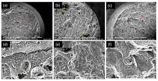
Figure 11.
Fractography samples: (a,d) 50 °C–5 h, (b,e) 50 °C–10 h, (c,f) 50 °C–15 h at various magnification. (Red: Propagation Yellow: Porosity).
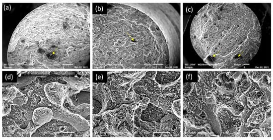
Figure 12.
Fractography samples: (a,d) 100 °C–4 h, (b,e) 100 °C–8 h, (c,f) 100 °C–12 h at various magnifications. Yellow arrows indicate porosity.
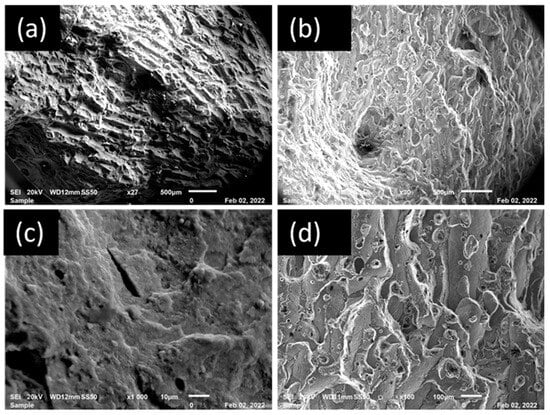
Figure 13.
Fractography images of samples quenched at 300 °C: (a,c) 2.5 h and (b,d) 3 h at various magnifications.
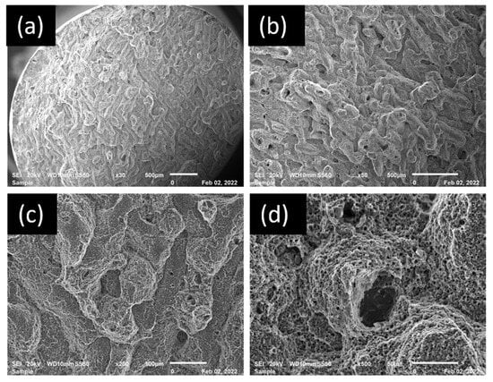
Figure 14.
Fractography images of samples quenched at 400 °C: (a,c) 2.5 h and (b,d) 3 h.
There is not much difference observed in Figure 12 relative to Figure 11 fractography. This is also observed in other characterisations, which show that, in both 50 °C and 100 °C, the samples yield significantly improved results with only slight variances from one another. The surface also shows inclusions with micro-voids, showing a forced fracture, though ductile relative to the as-built samples [1]. The pores, denoted in yellow, are observed on both Figures.
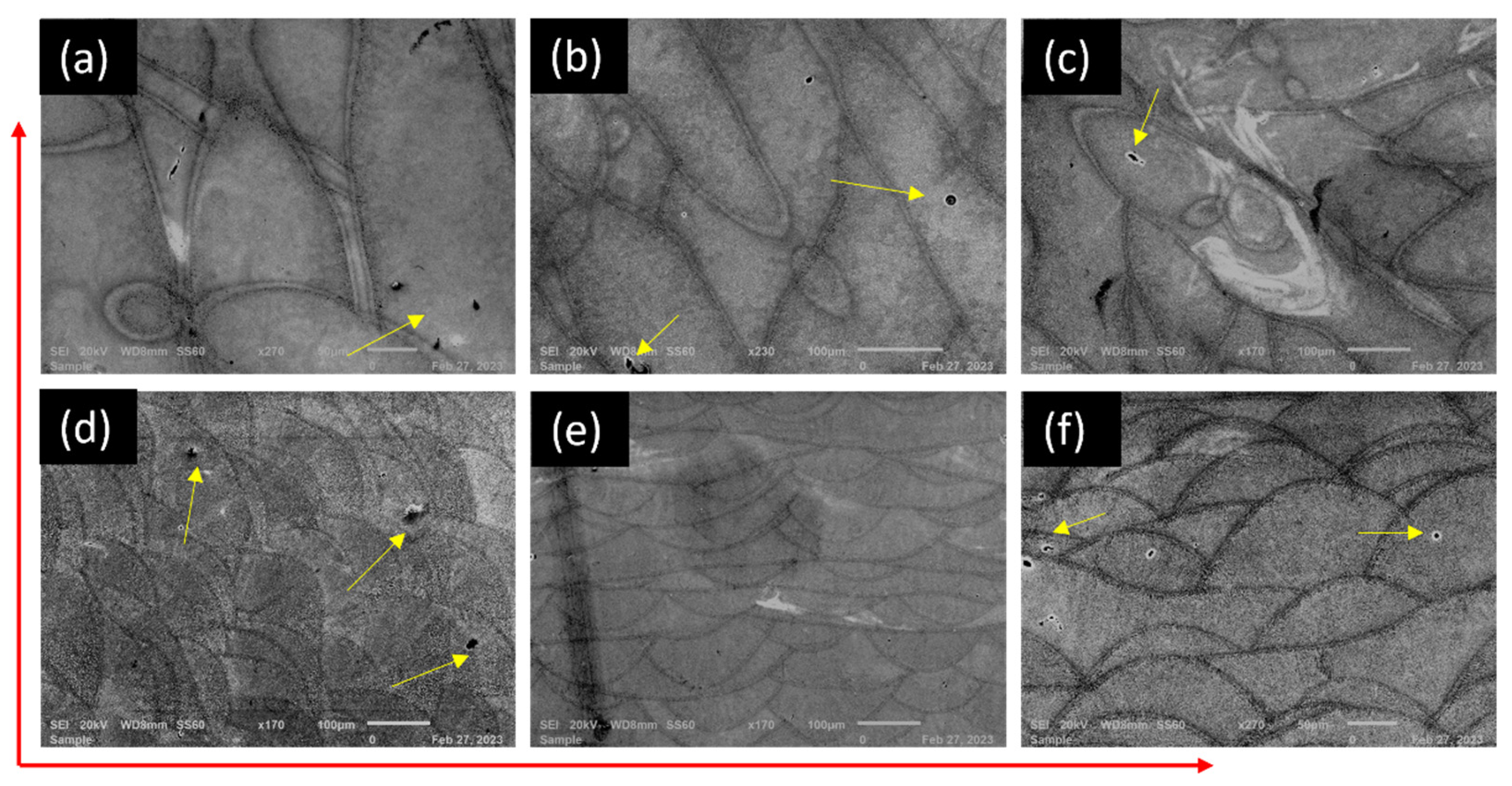
For the fractography micrographs of the samples, in Figure 13, a brittle fracture is observed in the (a and c) that exposes the structure of the fish-scale track segment and the longitudinal morphology, since the breaking of the swollen surface is clearly observed. The basis of malfunction for this sample seems to have been initialised at any arbitrary layer and then spread abruptly to the building direction through weak sites between layers [10]. Meanwhile, in (b and d), a small ductile fracture is observed relative to that of (a and c). In both fractography images, pores are observed.
The fractures are both more ductile as the dimples are more visible in correlation with Figure 6. Well, the time factor is also observed here, which supports the findings in the microstructural images where (b and d) thermal-treated at 300 °C and that of 400 °C at 3 h show more ductility in comparison with the (a and c) of both samples. The propagation is denoted by the yellow arrows in Figure Sample (d) consists of more dimples with micro-void coalescence relative to all of the samples. This is also shown in the elongation and modulus of elasticity. The (a) samples in both Figure 7 and Figure 17 also confirm the time factor that plays a role in the silicon fragmentation observed in the SEM microstructures. The track segments are seen in both samples, though they do not look the same because less silicon was expelled because the structure did not lose much of its track segments, although the track segments experience thermal shock, which rendered them invisible in the OM images. This also supports the argument that silicon does not need to disintegrate from the aluminium matrix when thermally treating AlSi10Mg.
3.5. Residual Stress Measurements
Figure 15, Figure 16, Figure 17 and Figure 18 are the results of residual stress measurements for the samples thermal-treated at 50 °C and 100 °C, as well as those ice-water-quenched at 300 °C and 400 °C.
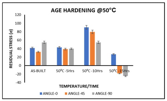
Figure 15.
Demonstrating the residual stress measurements of the thermal treatment of the samples at 50 °C.
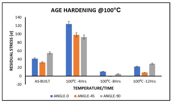
Figure 16.
Demonstrating the residual stress measurements of the samples’ thermal treatment at 100 °C.
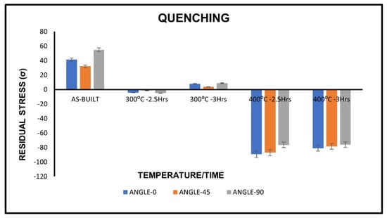
Figure 17.
Demonstrating the residual stress measurements of the samples’ ice-water-quenched at 300 °C and 400 °C.
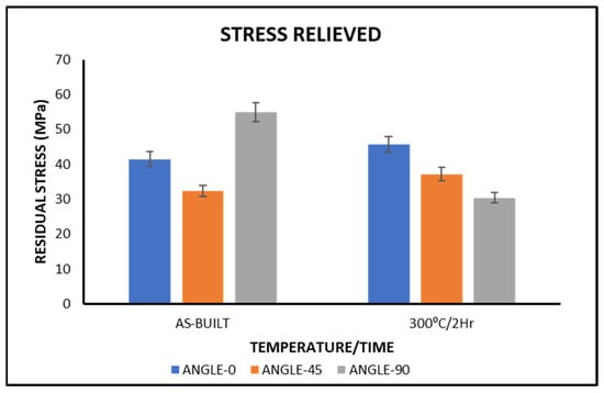
Figure 18.
Demonstrating the residual stress measurements of the samples’ stress relieved at 300 °C for 2 h.
The results of the samples thermally treated at 50 °C for 5 and 10 h demonstrate an increase in residual stress measurements, while the sample thermally treated at 50 °C for 15 h demonstrates a significant reduction to a point of negative residual stress measurements. Negative residual stresses are mathematically termed compressive residual stresses and are known to have a positive influence, especially during fatigue conditions, since they act as resistance to tensile stresses applied by keeping the crack faces closed to reduce destruction. This is because, for many structures, fatigue cracking is one type of damaging failure [32]. The fatigue life of a component can be improved by post-treatment, since compressive residual stresses can be induced on the surface, thus improving its hardness [33].
It must be recognised that the formation of residual stress in a component is primarily compared to all other manufacturing parameters and material factors [34]. Therefore, to avoid unsolicited transformation in the microstructure and material characteristics, the adoption of thermal treatment temperatures must be carried out with caution. It is observed in these results that the sample thermally treated at 100 °C for 4 h demonstrates an extreme increase in its residual stress measurements, while the samples thermally treated at 100 °C for 8 and 12 h demonstrate a significant reduction in their residual stress measurements. In this work, the expectation is for the aluminium matrix to diffuse to the stressed area of the sample in order to relieve the stress thereof. It is demonstrated in the samples thermal-treated at 100 °C for 8 and 12 h. The 8 h treatment is shown to be the effective thermal treatment parameter.
The results of the samples thermally treated by ice-water quenching at 300 °C demonstrate a high reduction in residual stress measurements, while the samples thermally treated by ice-water quenching at 400 °C demonstrate a drastic reduction to a point of negative residual stress measurements. According to Neves et al., compressive residual stresses are produced in quenching more than any other thermal treatment [13]. Compressive residual stresses are commonly known to decrease the influence of functional tensile stresses and, therefore, are considered useful, which, in recorded cases, subside in improving resistance to corrosion cracking stress and fatigue strength [35]. In this case, as observed in the samples ice-quenched at 400 °C, these compressive residual stresses occurred as a consequence of the thermal shock experienced by the samples. During the quenching process, the external surface of the metal cools the fastest relative to the internal. Therefore, the extension of the internal volume is limited by the rapid cooling of the external, which causes it to experience compression, while the external surface experiences tension [35]. Therefore, these samples experienced a severe volume change due to ice water to a point of stress that resulted in cracking of the samples. This is also evident in the increased elasticity of the samples ice-quenched at 400 °C, which was a result of plastic deformation.
The results of the samples thermally treated by stress relief at 300 °C for 2 h demonstrate an increase in residual stresses relative to the built samples. As agreed by Industrial Metallurgists, 2022, cooling the component from high temperatures induces residual stresses instead of relieving them as a result of the temperature difference, which causes thermal contractions. Inhomogeneous stress due to various cooling rates undergone by the internal and external chambers of the sample is established by thermal contractions, which then result in an increase in residual stresses [35]. These inhomogeneities are observed in the coarsening of the microstructure and the bulging of the sample [5,36]. As agreed by Frederico et al., residual stresses depend on the type of thermal treatment used, its intensity, and the nature of the original residual stresses on the material [13]. This may be the reason for the increase in residual stresses observed in Figure 10. Some residual stresses are a consequence of thermal treatment, as also previously observed by Camurri et al. [36,37].
4. Conclusions
- ○
- In this investigation, there is a justification that the age-hardening thermal treatment modifies the mechanical characteristics of AlSi10Mg constructively. There, the microstructure did not change, which was the key objective sought to be achieved for this investigation. This is observed with all samples age-hardened at temperatures of 50 °C and 100 °C for all variations in hours; even though the samples age-hardened at 50 °C for 10 h stand out as the most successful thus far in terms of hardness enhancement of 166 Hv, the rest of the age-hardened samples demonstrated a considerable hardness increase.
- ○
- In all samples, improvement was observed, although there was a minor compromise in ductility while work was performed to improve strength.
- ○
- The residual stress measurements meticulously selected the effective thermal treatment parameters to be 50 °C at 15 h and 100 °C at 8 and 12 h. The residual stresses were reduced to between 0 and −20 MPa, 0 and 10MPa, as well as between 0 and 20 MPa, respectively.
- ○
- In ice-quenched samples, whenever silicon is disintegrated at the eutectic boundaries, the microstructural and mechanical characteristics of AlSi10Mg are compromised. The idea of thermal treatment in AlSi10Mg samples is to precipitate Mg2Si and retain the scale-like microstructure, which is the original structure built, which is already near perfect and only in need of residual stress removal.
- ○
- It was observed that the residual stress was reduced to compressive residual stress at 400 °C to below 50 MPa and, for samples ice-quenched at 300 °C, the residual stress was reduced to slightly above 0 MPa, which tells us that the thermal treatment technique is effective at reducing residual stresses despite compromised mechanical characteristics.
- ○
- In future work, the quenching is suggested to be carried out at a lower temperature and samples to be quenched in water at 25 °C, which is room temperature. This should prevent thermal shock in the samples after being removed from the furnace. It also dawns that, with the stress relief thermal treatment, during air cooling or furnace cooling, the transformation still precedes; hence, the whole morphological evolution was observed with time.
Author Contributions
Conceptualisation, N.R.M. and B.J.M.; writing—original draft preparation, B.J.M.; writing—review and editing, B.J.M. and N.R.M.; preparation and supervision P.A.P. All authors have read and agreed to the published version of the manuscript.
Funding
Funding for the project was received from the South African Council of Science and Industrial Research. The National Research Foundation Grant No. 114675. The Department of Science and Innovation (DSI), Collaborative Programme on Additive Manufacturing (CPAM).
Data Availability Statement
The data presented in this study are available in the paper.
Acknowledgments
Metal Heart Additive Manufacturing, Tshwane University of Technology, Council for Scientific and Industrial Research (South Africa) is gratefully acknowledged. The authors also thank the National Laser Centre (NLC) Metallurgical Laboratory and Material Science and Manufacturing Mechanical Testing Laboratory for sample preparation and characterisation. The National Research Foundation Grant No. 114675 is acknowledged for conference funding. Acknowledgement also goes to the following individuals for their support: Ipfi Mathoho, Daniel Glaser, and Londiwe Motibane.
Conflicts of Interest
The authors declare no conflicts of interest.
References
- Mfusi, B.; Tshabalala, L.C.; Mathe, N.R. The effect of selective laser melting build orientation on the mechanical properties of AlSi10Mg parts. IOP Conf. Ser. Mater. Sci. Eng. 2018, 430, 012028. [Google Scholar] [CrossRef]
- Rosenthal, I.; Stern, A.; Frage, N. Microstructure and mechanical properties of AlSi10Mg parts produced by the laser beam additive manufacturing (AM) technology. Metallogr. Microstruct. Anal. 2014, 3, 448–453. [Google Scholar] [CrossRef]
- Brandão, A.D.; Gumpinger, J.; Gschweitl, M.; Seyfert, C.; Hofbauer, P.; Ghidini, T. Fatigue properties of additively manufactured AlSi10Mg–surface treatment effect. Procedia Struct. Integr. 2017, 7, 58–66. [Google Scholar] [CrossRef]
- Zhou, L.; Mehta, A.; Schulz, E.; McWilliams, B.; Cho, K.; Sohn, Y. Microstructure, precipitates and hardness of selectively laser melted AlSi10Mg alloy before and after heat treatment. Mater. Charact. 2018, 143, 5–17. [Google Scholar] [CrossRef]
- Mfusi, B.J.; Mathe, N.R.; Tshabalala, L.C.; Popoola, P.A. The effect of stress relief on the mechanical and fatigue properties of additively manufactured AlSi10Mg parts. Metals 2019, 9, 1216. [Google Scholar] [CrossRef]
- Mfusi, B.J. The Development of an Ideal Processing Window Using Selective Laser Melting Technology for Aluminium Based Components; Tshwane University of Technology: Pretoria, South Africa, 2019. [Google Scholar]
- Tradowsky, U.; White, J.; Ward, R.; Read, N.; Reimers, W.; Attallah, M. Selective laser melting of AlSi10Mg: Influence of post-processing on the microstructural and tensile properties development. Mater. Des. 2016, 105, 212–222. [Google Scholar] [CrossRef]
- Fiocchi, J.; Tuissi, A.; Bassani, P.; Biffi, C. Low temperature annealing dedicated to AlSi10Mg selective laser melting products. J. Alloys Compd. 2017, 695, 3402–3409. [Google Scholar] [CrossRef]
- Marola, S.; Manfredi, D.; Fiore, G.; Poletti, M.G.; Lombardi, M.; Fino, P.; Battezzati, L. A comparison of Selective Laser Melting with bulk rapid solidification of AlSi10Mg alloy. J. Alloys Compd. 2018, 742, 271–279. [Google Scholar] [CrossRef]
- Rosenthal, I.; Stern, A.; Frage, N. Strain rate sensitivity and fracture mechanism of AlSi10Mg parts produced by selective laser melting. Mater. Sci. Eng. A 2017, 682, 509–517. [Google Scholar] [CrossRef]
- Aboulkhair, N.T.; Maskery, I.; Tuck, C.; Ashcroft, I.; Everitt, N.M. The microstructure and mechanical properties of selectively laser melted AlSi10Mg: The effect of a conventional T6-like heat treatment. Mater. Sci. Eng. A 2016, 667, 139–146. [Google Scholar] [CrossRef]
- Li, W.; Li, S.; Liu, J.; Zhang, A.; Zhou, Y.; Wei, Q.; Yan, C.; Shi, Y. Effect of heat treatment on AlSi10Mg alloy fabricated by selective laser melting: Microstructure evolution, mechanical properties and fracture mechanism. Mater. Sci. Eng. A 2016, 663, 116–125. [Google Scholar] [CrossRef]
- Neves, F.O.; Oliviera, T.L.L.; Braga, D.U.; Silva, A.S.C.d. Influence of heat treatment on residual stress in cold-forged parts. Adv. Mater. Sci. Eng. 2014, 2014, 658679. [Google Scholar] [CrossRef]
- Mathe, N.R.; Tshabalala, L.C. The validation of the microstructural evolution of selective laser-melted AlSi10Mg on the in-house built machine: Energy density studies. Prog. Addit. Manuf. 2019, 4, 431–442. [Google Scholar] [CrossRef]
- Mfusi, B.J.; Mathe, N.R.; Popoola, P.; Tshabalala, L.C. Influence of stress relieving thermal cycles on AISI10Mg specimens produced by selective laser melting. In IOP Conference Series: Materials Science and Engineering; IOP Publishing: Bristol, UK, 2019. [Google Scholar]
- Cabrini, M.; Lorenzi, S.; Pastore, T.; Pellegrini, S.; Ambrosio, E.; Calignano, F.; Manfredi, D.; Pavese, M.; Fino, P. Effect of heat treatment on corrosion resistance of DMLS AlSi10Mg alloy. Electrochim. Acta 2016, 206, 346–355. [Google Scholar] [CrossRef]
- Friend, C.; Luxton, S. The effect of δ alumina fibre arrays on the age-hardening characteristics of an Al-Mg-Si alloy. J. Mater. Sci. 1988, 23, 3173–3180. [Google Scholar] [CrossRef]
- Lam, L.; Zhang, D.; Liu, Z.; Chua, C. Phase analysis and microstructure characterisation of AlSi10Mg parts produced by Selective Laser Melting. Virtual Phys. Prototyp. 2015, 10, 207–215. [Google Scholar] [CrossRef]
- Mertens, A.; Dedry, O.; Reuter, D.; Rigo, O.; Lecomte-Beckers, J. Thermal treatments of AlSi10Mg processed by laser beam melting. In Proceedings of the International Solid Freeform Fabrication Symposium, Austin, TX, USA, 10–12 August 2015; pp. 1007–1016. [Google Scholar]
- Cheng, B.; Chou, K. Melt pool evolution study in selective laser melting. In Proceedings of the 26th Annual International Solid Freeform Fabrication Symposium-An Additive Manufacturing Conference, Austin, TX, USA, 25–27 July 2022; pp. 1182–1194. [Google Scholar]
- Kempen, K.; Thijs, L.; Van Humbeeck, J.; Kruth, J.-P. Mechanical properties of AlSi10Mg produced by selective laser melting. Phys. Procedia 2012, 39, 439–446. [Google Scholar] [CrossRef]
- Brandl, E.; Heckenberger, U.; Holzinger, V.; Buchbinder, D. Additive manufactured AlSi10Mg samples using Selective Laser Melting (SLM): Microstructure, high cycle fatigue, and fracture behavior. Mater. Des. 2012, 34, 159–169. [Google Scholar] [CrossRef]
- Fousová, M.; Dvorský, D.; Michalcová, A.; Vojtěch, D. Changes in the microstructure and mechanical properties of additively manufactured AlSi10Mg alloy after exposure to elevated temperatures. Mater. Charact. 2018, 137, 119–126. [Google Scholar] [CrossRef]
- Yang, P.; Rodriguez, M.A.; Deibler, L.A.; Jared, B.H.; Griego, J.; Kilgo, A.; Allen, A.; Stefan, D.K. Effect of thermal annealing on microstructure evolution and mechanical behavior of an additive manufactured AlSi10Mg part. J. Mater. Res. 2018, 33, 1701–1712. [Google Scholar] [CrossRef]
- Liu, M.; Zhang, Z.; Breton, F.; Chen, X. Investigation of the quench sensitivity of an AlSi10Mg alloy in permanent mold and high-pressure vacuum die castings. Materials 2019, 12, 1876. [Google Scholar] [CrossRef] [PubMed]
- Xiaohui, J.; Chunbo, Y.; Honglan, G.; Shan, G.; Yong, Z. Effect of supporting structure design on residual stresses in selective laser melting of AlSi10Mg. Int. J. Adv. Manuf. Technol. 2022, 118, 1597–1608. [Google Scholar] [CrossRef]
- Strobel, K.; Lay, M.D.; Easton, M.A.; Sweet, L.; Zhu, S.; Parson, N.C.; Hill, A.J. Effects of quench rate and natural ageing on the age hardening behaviour of aluminium alloy AA6060. Mater. Charact. 2016, 111, 43–52. [Google Scholar] [CrossRef]
- Alghamdi, F.; Song, X.; Hadadzadeh, A.; Shalchi-Amirkhiz, B.; Mohammadi, M.; Haghshenas, M. Post heat treatment of additive manufactured AlSi10Mg: On silicon morphology, texture and small-scale properties. Mater. Sci. Eng. A 2020, 783, 139296. [Google Scholar] [CrossRef]
- Welsch, G.; Lütjering, G.; Gazioglu, K.; Bunk, W. Deformation characteristics of age hardened Ti-6Al-4V. Metall. Trans. A 1977, 8, 169–177. [Google Scholar] [CrossRef]
- Banerjee, M. Age-hardening characteristics of aluminium–chromium alloys. J. Mater. Sci. 1997, 32, 6645–6651. [Google Scholar] [CrossRef]
- Kempen, K.; Thijs, L.; Yasa, E.; Badrossamay, M.; Verheecke, W.; Kruth, J. Process optimization and microstructural analysis for selective laser melting of AlSi10Mg. In Proceedings of the Solid Freeform Fabrication Symposium, Austin, TX, USA, 8–10 August 2011; pp. 484–495. [Google Scholar]
- Xing, X.; Duan, X.; Sun, X.; Gong, H.; Wang, L.; Jiang, F. Modification of residual stresses in laser additive manufactured AlSi10Mg specimens using an ultrasonic peening technique. Materials 2019, 12, 455. [Google Scholar] [CrossRef]
- Teixeira, Ó.; Silva, F.J.; Ferreira, L.P.; Atzeni, E. A review of heat treatments on improving the quality and residual stresses of the Ti–6Al–4V parts produced by additive manufacturing. Metals 2020, 10, 1006. [Google Scholar] [CrossRef]
- Bartlett, J.L.; Li, X. An overview of residual stresses in metal powder bed fusion. Addit. Manuf. 2019, 27, 131–149. [Google Scholar] [CrossRef]
- Industrial Metallurgists. Causes of Residual Stress. 2022. Available online: https://www.imetllc.com/residual-stress/#:~:text=Residual%20stress%20due%20to%20temperature,during%20heat%20treating%20and%20welding (accessed on 15 October 2023).
- Mungi, M.; Rasane, S.; Dixit, P. Residual stresses in cold axisymmetric forging. J. Mater. Process. Technol. 2003, 142, 256–266. [Google Scholar] [CrossRef]
- Camurri, C.; Carrasco, C.; Dille, J. Residual stress during heat treatment of steel grinding balls. J. Mater. Process. Technol. 2008, 208, 450–456. [Google Scholar] [CrossRef]


Disclaimer/Publisher’s Note: The statements, opinions and data contained in all publications are solely those of the individual author(s) and contributor(s) and not of MDPI and/or the editor(s). MDPI and/or the editor(s) disclaim responsibility for any injury to people or property resulting from any ideas, methods, instructions or products referred to in the content. |
© 2024 by the authors. Licensee MDPI, Basel, Switzerland. This article is an open access article distributed under the terms and conditions of the Creative Commons Attribution (CC BY) license (https://creativecommons.org/licenses/by/4.0/).