Article

On the Macrosegregation of Continuous Casting of High Carbon Steel Billet with Strand Reduction Process

1
State Key Laboratory of Advanced Metallurgy, University of Science and Technology Beijing, Beijing 100083, China
2
Technology Center, Zenith Steel Co., Ltd., Changzhou 213000, China
*
Author to whom correspondence should be addressed.
Metals 2024, 14(2), 157; https://doi.org/10.3390/met14020157
Submission received: 12 December 2023 / Revised: 5 January 2024 / Accepted: 11 January 2024 / Published: 27 January 2024

Abstract

:
A mathematical model of the macrosegregation of continuous cast high carbon steel billet was developed based upon a representative volume element, considering the flow of enriched liquid, solidification rate, and solidification shrinkage as well. It was found that a lower casting velocity, higher cooling intensity, and shorter solidification interval positively contributed to the inhibition of macrosegregation in a continuously cast billet when a mechanical reduction process was not applied. A numerical expression for the relative flow velocity of liquid was further proposed incorporating such aspects as casting velocity, densities of different phases, and the variation of cross section areas as well. The analysis based on this numerical expression indicated that the overall effect of the reduction process on the macrosegregation of billets depended not only on the reduction zone but also on the reduction amount and its distribution for the active reduction rolls. The test results of further practical plant trials demonstrated a reasonable agreement with the predictions obtained from the proposed numerical model, indicating the reliability of this analysis model to be employed for the continuous casting of high carbon steel billet with strand reduction process.

1. Introduction

High carbon steel has a high likelihood of experiencing macrosegregation during continuous casting due to its relatively wide solidification range and a large mushy zone. Macrosegregation, which refers to chemical non-uniformity over a macroscopic size, can hardly be removed or greatly reduced even after prolonged heat treatment at elevated temperatures. Thus, it is regarded as a prime cause of large variations in mechanical properties and may even give rise to premature failure of the final high carbon steel products [1]. In addition, the trend towards higher casting speeds prevails in continuous casting in recent years, on account of the requirement for high productivity. This may further increase the tendency and severity of macrosegregation for high carbon steel strand. Therefore, it is of great significance to study the macrosegretation of high carbon steel in continuously cast products.
It is well known that during the solidification of steel, solute partitioning at the solid–liquid interface induces a compositional difference between the solid and liquid phases. Macrosegregation may form when the solute enriched material melts adjacent to some solid and is swept away by the relative motion between the solid and its surrounding liquid [2]. The level of segregation is usually more pronounced along the core part of a continuous cast strand, since the flow velocity component in the casting direction is highest in center due to the lowest resistance of the mushy zone [3].
Numerous experimental research works were conducted to study the effects of continuous casting conditions on macrosegregation [4,5], and several numerical simulations were also carried out to have an in-depth understanding or description of macrosegregtion during continuous casting. Oh et al. investigated the influence of various Electro-Magnetic Stirring (EMS) modes on macrosegregation by conducting a series of plant tests using a continuous bloom caster and a billet caster of POSCO as well as the relevant laboratory experiments for the different steel grades [6]. The mechanism for reduction macrosegregation was ascribed to the enhanced solidification rate, finely distributed segregation spots in the whole center region, and narrowed width of the mushy zone during the final stage of solidification under a combination stirring mode. Grundy et al. calculated the solidification of high carbon tire cord grade C80D cast as a 150 × 150 mm2 billet with state-of-the-art software packages [7], and they found that the most probable mechanism by which hard cooling reduced segregation was through the trapping of solutes between the intricately branched dendrite microstructure achieved by hard secondary cooling intensity. However, this model was based on many simplifications, including a neglection of the effect of fluid flow, which is actually closely related to the segregation of casting. In addition, there was no coupling between the models. Choudh et al. established a conjugate fluid flow–heat transfer model for low carbon continuously cast steel billets so as to correlate predictions based on the mathematical modelling of heat transfer with the experimental observations on macrosegregation and morphology [8]. Segregation equations based on various models were tested and verified for their applicability at the CET boundary of the billet transverse sections, however, no agreement was found with the data predicted for the centerline of the billet. Zhang et al. studied the effect of M-EMS on the macrosegregation in continuously cast steel billets through a three-phase volume average model [9]. Although a satisfactory agreement between the numerically calculated and experimentally determined as-cast structure was achieved, it is thought that further laboratory or in-plant experiments were required to quantify some modeling parameters, which were estimated based on a numerical parameter study. Dong et al. developed macrosegregation models, coupling fluid flow, heat, and solute transport with different microsegregation models to study the continuous casting of round billets [10]. They found that the choice of microsegregation model applied in the simulations resulted in the differently predicted segregations, which varied in regard to solute elements due to the influence of solute back-diffusion coefficients. Jiang et al. established a coupled numerical model, considering macroscale heat transfer and fluid flow, as well as microscale grain nucleation and crystal growth, to investigate the high carbon steel billet solidification structure and macrosegregation with dual electromagnetic stirrings in the mold and the final stage of solidification [11]. The optimal current intensities of M-EMS and F-EMS were proposed for the specific high carbon steel studied numerically. However, this work is also restricted to the application of EMS, which is thought to be not adequate to eliminate the macrosegregation of continuously cast high carbon steels [12,13].
As for the improvement of macrosegregation in continuous casting strand, mechanical reduction is regarded as one of the most effective technologies and has increasingly been applied in recent years. Several researchers have carried out corresponding numerical studies for the mechanical reduction process of continuous casting. Jiang et al. built a 3D model to simulate the transport behavior in the slab continuous casting with mechanical reduction and investigated the reduction amounts and reduction positions on the center segregation evolution [14]. Yang et al. established both a heat transfer model and a reduction model to improve the macrosegregation of bloom [15]. Hu et al. studied continuous casting round blooms with different solidification end reduction strategies with a series of three thermal–mechanical coupling models, and the advantages and disadvantages of each reduction scheme were discussed [16]. However, almost all previous numerical studies on the mechanical reduction process were performed either for slab or bloom, but effort has seldom been devoted to the billet. This is probably because the mechanical reduction process up to now was applied mainly for bloom and slab [17,18,19], but rarely for billet due to various aspects of factors [20] such as a lower reduction efficiency and a lack of support rolls to provide adequate mechanical pressure. Moreover, the reduction process and its working mechanism is rather obscure and complicated. Consequently, there is hardly any numerical analysis model employed for the mechanical reduction process of steel billet, not to mention for the actual production application.
Nevertheless, as the steel market asserts a more urgent claim for a high carbon billet with high homogeneity, and also with the continuous upgrading of modern equipped continuous casters for billet, the mechanical reduction process has recently been successfully applied in the continuous casting of steel billet [21,22]. This makes the numerical analysis of the mechanical reduction process for steel billet more important for practical implementation than ever, and it actually also turns out to provide an experimental way to verify the numerical study of this process for high carbon steel billet in terms of practical validity.
In this paper, firstly, a mathematical analysis model was developed particularly considering the solidification features of the billet, so as to study the effects of different major casting parameters on the macrosegregation in the continuously cast high carbon steel billet. The utility of mechanical reduction on depression of macrosegregation in billets with different process parameters was estimated by proposing a numerical expression for the relative flow velocity of liquid, when mechanical reduction was applied for the continuous casting of high carbon steel. The validity and reliability of the practical application of this analysis model was further tested and verified by industrial trials and the corresponding testing results. As for the motivations of this study, it is helpful to deepen our understanding of the mechanism for the process of mechanical reduction used for billet, providing a theoretical basis for further process optimization. Furthermore, it may even be of considerable significance for the future progress in promoting this mechanical reduction process of billet for more wide application in industry.

2. Development and Application of Numerical Analysis Model

2.1. Numerical Criteria for Macrosegregation of High Carbon Steel Billet

To establish the analysis model, a “Representative Volume Element” (RVE) [2] is employed in this study (as shown in Figure 1) and is considered as the volume at a certain position of the billet in space that is large enough to include multiple microstructure features and small enough that the important variations in the temperature, enthalpy, density, concentration, and volume fraction of the different phases can be assumed to be uniform over the RVE, and is supposed to be constant but may vary with time and distance. In the element volume, solid back diffusion and solidified shell contraction are not considered, and the element volume consists of liquid and solid phases. The mass or species of the RVE is varied through the relative motion of the liquid phase.
For the RVE, we can obtain the subsequent expression from the conservation of mass [3,23]:
ρ ¯ t + ρ l g l ν l , r e l = 0
Similarly, the conservation of solute gives [3]:
( ρ ¯ C ¯ ) t + ρ l g l C l ν l , r e l = 0
The above expression can transform to:
( ρ ¯ C ¯ ) t = C l ρ l g l ν l , r e l ρ l g l ν l , r e l C l
Substituting Equation (1) into Equation (3) gives:
( ρ ¯ C ¯ ) t = C l ρ ¯ t ρ l g l ν l , r e l C l
The total variation of solute in RVE equals to the sum of solute variations both in liquid and solid, therefore:
( ρ ¯ C ¯ ) t = t ( C s ¯ ρ s g s + C l ρ l g l )
Since no gas phase is generated or contained in this element volume, this gives:
g s + g l = 1
It further transforms to:
g s = 1 g l
By substituting Equation (7) into Equation (5), assuming the density of the solid phase to be constant, and with K = C s ¯ C l , we can obtain:
( ρ ¯ C ¯ ) t = K C l ρ s g s t + ρ l g l C l t + C l ( ρ l g l ) t
The relation of average density and densities of different phases gives:
( ρ ¯ ) t = t ( ρ l g l + ρ s g s )
By integrating Equation (9) into Equation (4) and combining with Equation (8), we obtain:
C l t ( ρ s g s + ρ l g l ) ρ l g l ν l , r e l C l = K C l ρ s g s t + ρ l g l C l t + C l ( ρ l g l ) t
Defining β as β = ρ s ρ l ρ l and integrating Equation (7), g s = 1 g l , into Equation (10) gives:
C l t = ( 1 K 1 β ) C l g l g l t ν l , r e l C l
The temperature of the RVE can be expressed as:
T = φ ( x , y , z , t )
The above equation further gives:
d T = d A T + T t d t
where, d A represents the shifting direction and distance of the isotherm line in RVE and could be given as:
d A = i d x + j d y + k d z
It was shown that the melt velocity component in the casting direction is much larger than the velocity component in the horizontal direction towards the outer surface [24], and is especially remarkable for the continuously cast billet. In the extreme case, that the horizontal permeability is much smaller than the permeability in the casting direction, the liquid flows only in the casting direction. The solidification of billet in this case is simplified as unidirectional solidification proceeding in the opposite direction to the casting direction. Since the casting direction is the only direction considered here, Equation (13) can be simplified as follows:
d T = d i T + T t d t
Meanwhile, temperature and concentration are assumed to be uniform in the element volume and may vary with time. This gives the following equation:
d i T + T t d t = 0
Equation (16) can transform to:
T t = d i d t T
Defining d i d t = u , where the negative sign means the temperature gradient moves in an opposite direction to isotherm line and the solidification of billet proceeds opposite to the casting direction, therefore:
T t = u T
The shifting of the isoconcentration line is the same as the isotherm line and this gives:
C l t = u C l
Integrating Equation (19) into Equation (11) gives:
C l t = ( 1 K 1 β ) C l g l g l t ν l , r e l u C l t
Assuming C s = C ¯ when fs = 1, where C ¯ represents the initial average concentration of solute in the RVE, the integration of Equation (20) can be calculated with upper and lower integration limits, resulting in:
( K 1 ) ln g l = ( 1 β ) ( 1 + ν l , r e l u ) ln C l C ¯
Defining q as q = ( 1 β ) ( 1 + ν l , r e l u ) , the concentration of solid C s is obtained as follows:
C s = K C ¯ ( 1 g s ) ( K 1 q )
The average concentration of solid C s ¯ could be further calculated as:
C s ¯ = 0 1 C S d g s = 0 1 K C ¯ ( 1 g s ) ( K 1 q ) d g s = K C ¯ q K 1 + q
From Equation (23) we can find that, when q = 1 , both the flow and solidification are moved in the same direction opposite to casting and with a v l , r e l u value equal to β ( 1 β ) , the result is no macrosegregation ( q = 1 ), which means the flow is just that required to feed solidification shrinkage in a unidirectional solidification. Flow that is greater with a direction opposite to the casting direction and a v l , r e l u value more than β ( 1 β ) results in negative segregation ( q > 1 ); a velocity of backward flow that is less, or flow in the same direction as casting, results in positive macrosegregation ( q < 1 ).

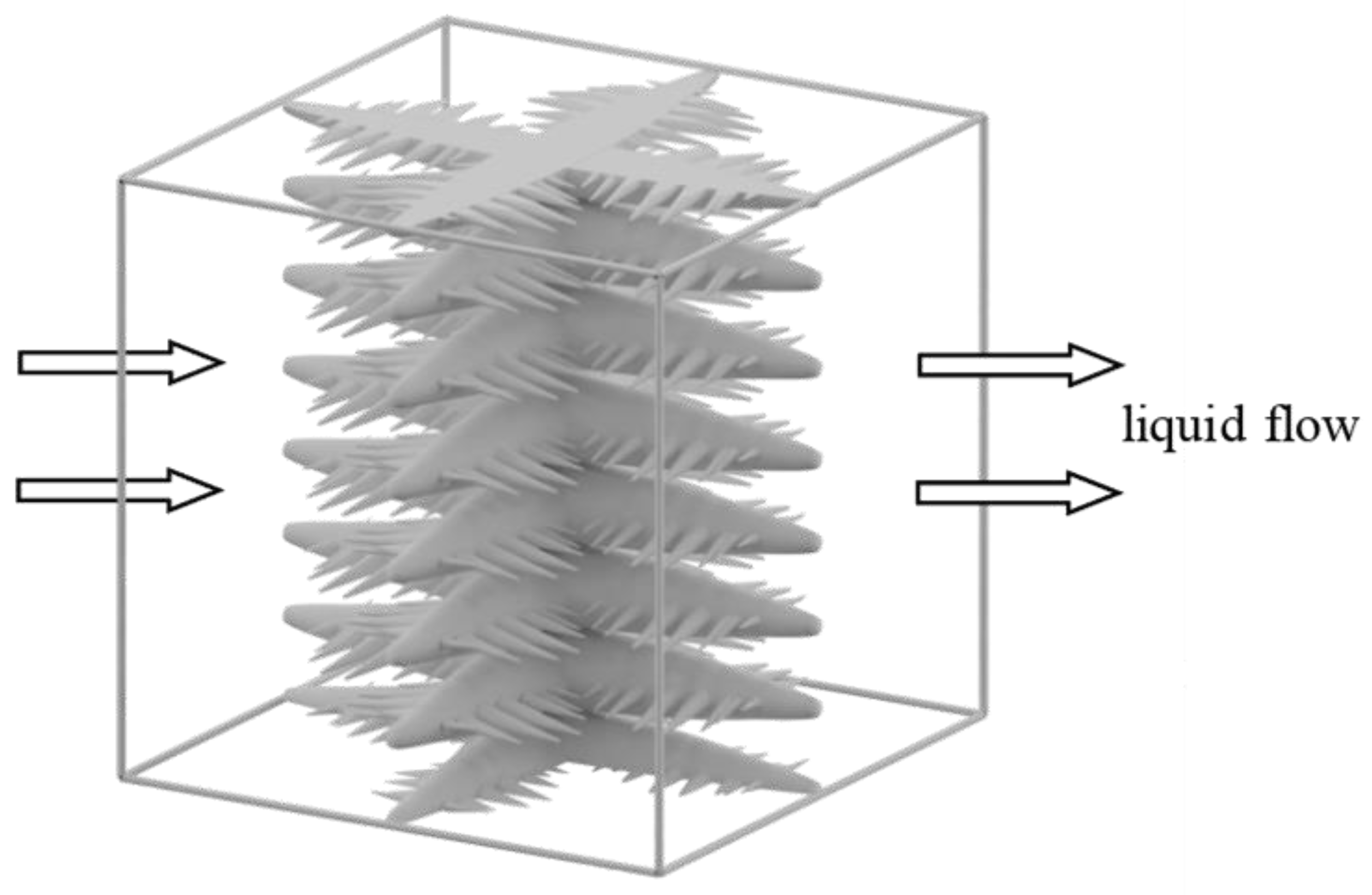
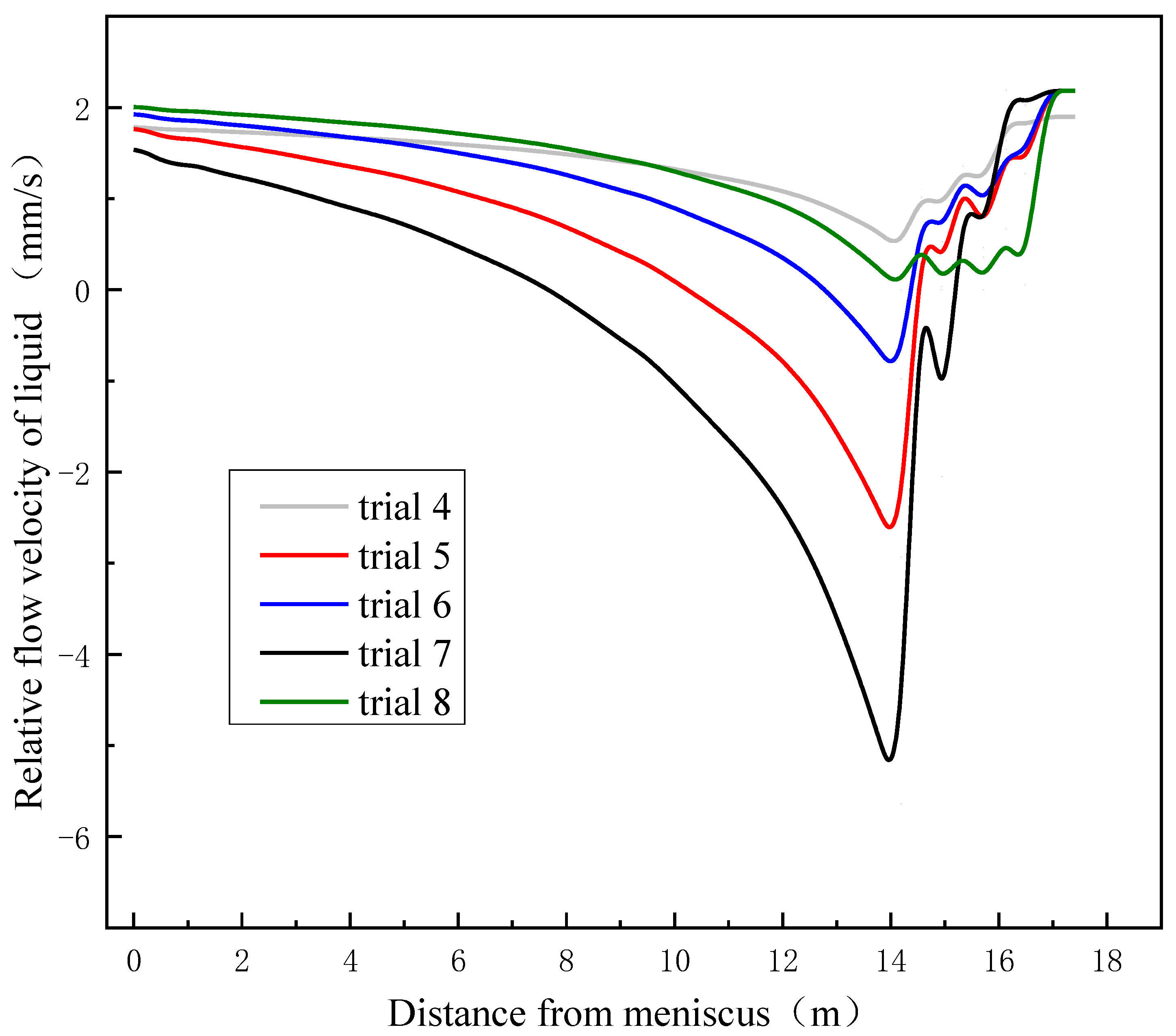
2.2. Mathematical Expression for Relative Flow Velocity of Liquid

As we can learn from the above analysis model, macrosegregation of billet is closely related to the relative flow velocity of liquid. Therefore, further efforts are made for the mathematical expression for relative flow velocity of liquid.
The continuous cast billet is mapped onto a regular cuboid domain which is shown in Figure 2. In this domain, the cross section of billet A x consists of liquid area A l and solid area A s . These cross section areas may vary with time and distance. The flow velocities of liquid and solid along the strand, v l and v s , are averaged over the cross section and the relative average flow velocity of liquid v ¯ l , r e l = v l v s .
In the calculated domain, since the variation of average specific mass is caused by the material feeding or extraction due to relative flow of liquid, thus:
ρ ¯ t = ρ l g l ν ¯ l , r e l
Combining the above equation with ρ ¯ = ρ l g l + ρ s g s gives:
t ( ρ s g s + ρ l g l ) = ρ l g l ν ¯ l , r e l
For the calculated domain, the relation between cross section area and volume fraction for different phases could be described as:
A i = A g i
where, gi is the volume fraction of the phases, with subscript “i” denoting phase i (i = l for liquid, i = s for solid).
Combining Equation (25) and Equation (26) gives:
t ( ρ s A s + ρ l A l ) = ρ l A l ν ¯ l , r e l = x ( ρ l A l ν ¯ l , r e l )
The relative average velocity of liquid could be calculated by integrating Equation (27) as:
ν ¯ l , r e l = 1 A l ρ l x o x t ( A l ρ l + A s ρ s ) d x
The lower integration limit x 0 equals to the distance from the meniscus where the cross section is just completely solidified, while the upper integration limit is equal to a distance x from the meniscus.
The relation of time and distance is simply given by:
t = x v c a s t
Substituting this expression of time into Equation (28) gives:
ν ¯ l , r e l x = v c a s t 1 A l , x ρ l x 0 x x ( A l , x ρ l + A s , x ρ s ) d x
The relative velocity of liquid in the casting direction can be derived from the integration of the above equation, and this gives:
ν ¯ l , r e l x = v c a s t 1 A l , x ρ l ( A l , x ρ l + A s , x ρ s A l , x 0 ρ l A s , x 0 ρ s )
Since thermal contraction is not considered, A s , x 0 = A x 0 , and with A l , x 0 = 0 , Equation (31) further transforms to:
ν ¯ l , r e l x = v c a s t [ 1 ρ s ρ l + ( A x A x 0 ) ρ s A l , x ρ l ]
where, the cross section area values for A x , A x 0 , and A l , x are read-in values from the 3D thermal–mechanical coupling simulation using the commercial software MSC Marc (2018), which will be described in detail the establishment principle in Section 3.1.
Based on Equation (32), it is not difficult to find that the average flow velocity of liquid is modified by the difference of densities between liquid and solid, which causes the shrinkage. The liquid flows in order to compensate for the increased specific mass of the solid as solidification proceeds. The average flow velocity of liquid is also dependent on cross section area changes of each phase at different distances caused by deformation, which mainly results from mechanical reduction as the contribution of thermal contraction is not considered here. When the mechanical reduction is applied to the billet at the end of solidification, because of a smaller deformation resistance, the deformation of liquid is larger than solid. Meanwhile, due to the closed volume of liquid behind the working pinch roll for reduction, the liquid is pushed back in the opposite direction of casting. This push-back flow of liquid will retard the relative motion between liquid and solid, the relative flow velocity of liquid is reduced, and therefore positive macrosegregation is alleviated. If the push-back flow of liquid is greater than the value we mention in Section 2.1, it may even lead to the occurrence of obvious negative macrosegregation. This is how the reduction process affects the macrosegregation of billet in view of the relative flow vector of liquid.

3. Materials and Methods

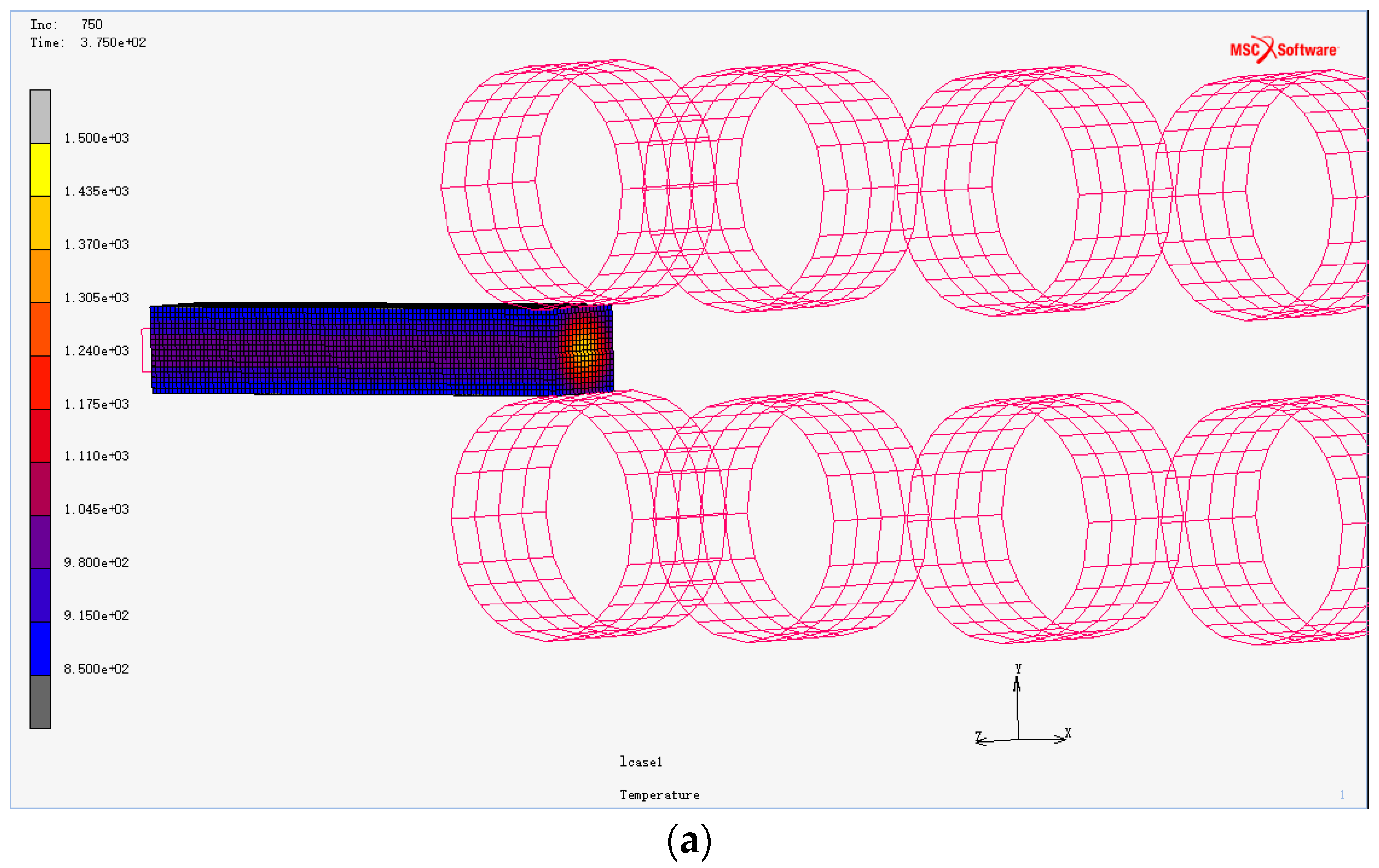
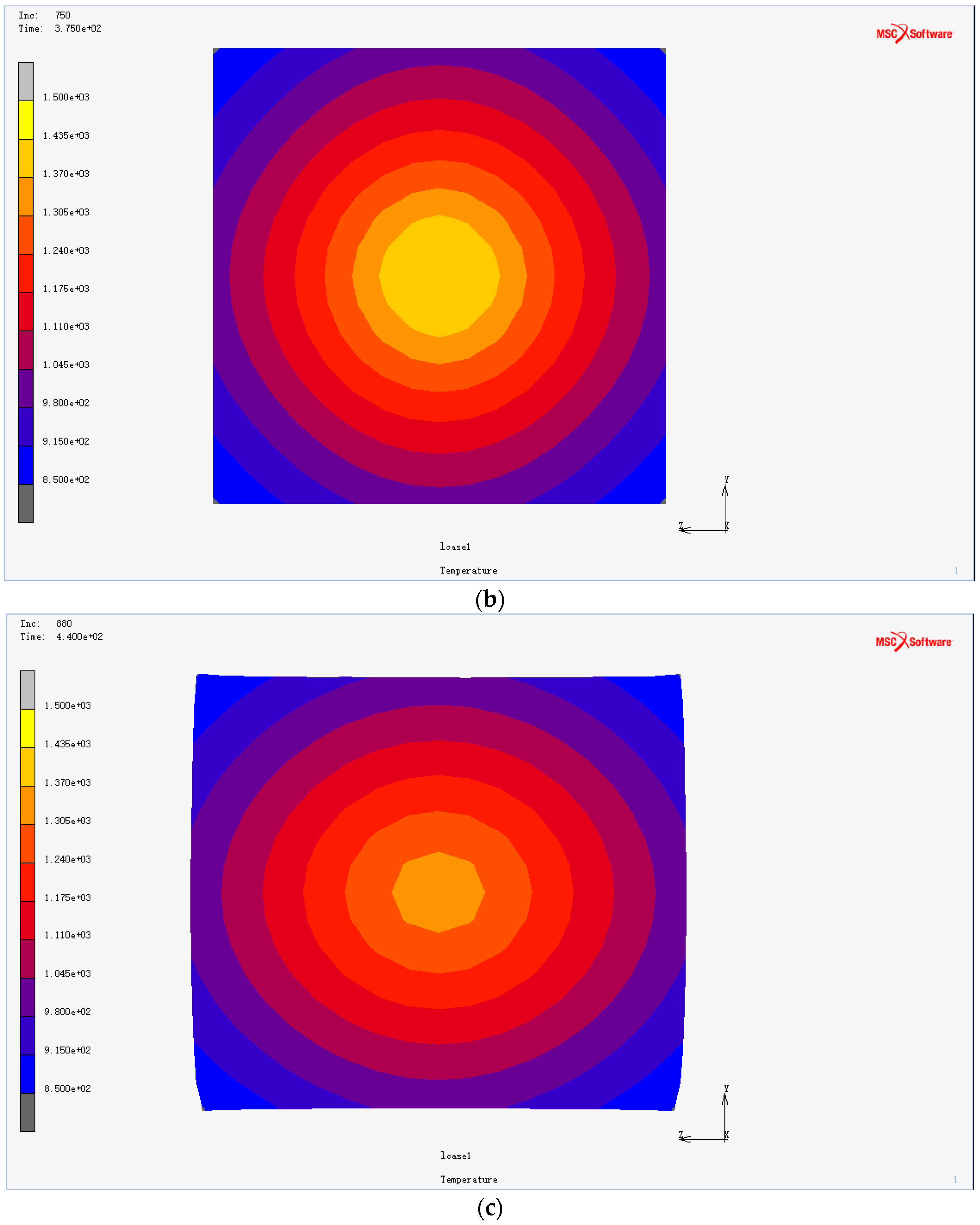
3.1. Description of Thermal–Mechancial Coupling Simulation

A 3D thermal–mechanical coupled model was developed by the commercial finite element software MSC Marc 2018 to simulate the heat transfer and deformation behavior of billets during the reduction process. The heat transfer equation and constitutive equation used for this 3D thermal–mechanical coupled model were introduced in authors’ previous work [25] and relevant literature [26]. The thermal material properties of the studied steel grade such as thermal conductivity, solidification latent heat, and specific heat capacity were obtained by the JMatPro software (JmatPro 12.0), while the relevant mechanical parameters, such as Young’s modulus and Poisson’s ratio are adopted from relevant references [27,28].
The initial temperature of the heat transfer model was set to 1498 °C, which is the most common temperature in industrial practice for the steel grade studied in this case. The temperature distribution calculated as the billet begins to be reduced was taken as the initial condition of the model for mechanical reduction. During the mechanical reduction of the billet, the heat transfer between the reduction roller and the billet is negligible compared with the dominant effect of radiation, and the heat flux at the surface of the billet was calculated by the Stefan–Boltzmann equation, in which the emissivity of the billet was set to 0.8.
In the simulated reduction process, reduction rollers were regarded as rigid bodies without deformation, while the billet was treated as a deformable body. The friction coefficient between the reduction roller and the billet was assumed to be 0.3. The billet length and cross section were set as 1000 mm and 160 mm × 160 mm, respectively. The schematic diagram of 3D thermal–mechanical coupled model of the reduction process is shown in Figure 3a, and the typical morphology and temperature distribution contour maps of transverse cross sections at different distances from the meniscus in a specific casting condition with reduction process are illustrated in Figure 3b,c for instance.

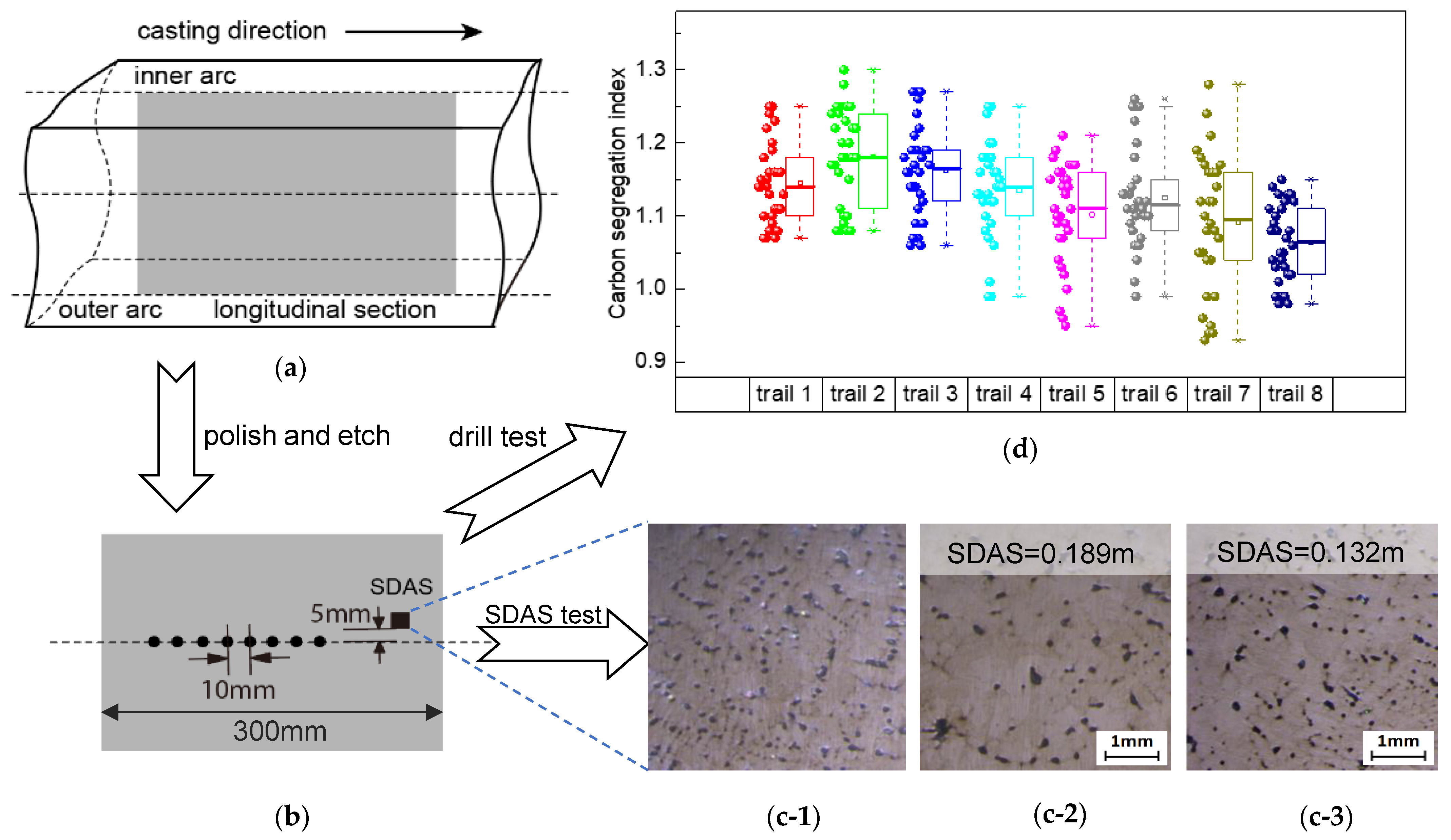
3.2. Description of Plant Trials

Plant trials were carried out in an arc-type billet caster with cross section size of 160 mm × 160 mm; the basic caster parameters are listed in Table 1. As for trials with mechanical reduction, four pinch rollers located between 14.2 m~16.3 m from the meniscus were employed. The chemical composition of the high carbon steel grade used in this study is listed in Table 2. The detailed operation conditions for different trials are listed in Table 3.
The reduction zones covered by different trials listed in Table 3 were estimated on the basis of the temperature distribution and solidification profile obtained from the thermal part of the simulation model described in Section 3.1, which were validated both by the method of surface temperature measuring for temperature field and by single-roller reduction crack test for the solidification profile as stated in authors’ previous work [19]. Moreover, the validity of the mathematical analysis and accuracy of the simulation model may further be verified by the comparison of the predictions based on the numerical model and the experimental results that will be discussed in the following section.
Central longitudinal sections of billet with a length of 300 mm were collected for macrostructure etching with a 50% hydrochloric acid aqueous solution at 80 °C for 20 min.
Macrosegregation of billets was evaluated by the drilling of chips. With the drill of 5 mm in diameter up to 5 mm in depth at the solidification center of the central longitudinal section, 30 holes were drilled consecutively at an interval of 10 mm. Chemical analysis of carbon for these samples were further carried out in the Leco carbon analyzer (Leco CS744). The carbon segregation index was defined as Ci/Co and the average, minimum, and maximum center segregation of carbon could be calculated as Cavg/Co, Cmin/Co, and Cmax/Co, respectively, where Ci denotes concentration of carbon at the specific sampling location and Co is the bulk carbon content determined with liquid steel in the tundish. Cmin, Cmax, and Cavg represent the minimum, maximum, and average carbon content of all samples, respectively.
Secondary dendrite arm spacing (SDAS) was used to evaluate the permeability of specific parts of the billet at the end of solidification. It was measured at the identical positions of longitudinal-section samples in the core part of billets as shown in Figure 4b. 20 measurements were recorded for each sample, and the average value of these measurements was taken.

4. Results and Discussion

The corresponding macrostructure images of longitudinal sections are given in Figure 5 and the test results for macrosegregation of carbon are shown in Table 4 and Figure 4d.
We can find from the experimental results of trial 1 and trial 2 that the macrosegregation severity is aggravated as the casting speed increases. With the increment of casting speed, the width and length of the liquid core (mushy zone) is increased, and the solidification interval enlarges the more developed the dendrites are, showing a larger value of secondary dendrite arm spacing, as shown in Figure 4(c-1),(c-2), leading to a higher permeability for enriched interdendrite melt. More important is that the relative flow velocity of liquid increases with the casting speed, as indicated by Equation (31).
On the other hand, the rising intensity of secondary cooling seems to be beneficial for the alleviating of macrosegregation in billets as indicated with the test results of trial 2 and 3. A higher secondary cooling intensity leads to a higher cooling rate, and the solidification duration is shortened. Meanwhile, SDAS reduces as cooling rate increases, as we can learn from Figure 4(c-2),(c-3), and as the permeability of the mushy zone should be reduced as indicated by Darcy’s Law [29] and the Carman–Kozeny Equation [30], this may further decrease the relative velocity of the liquid phase. Thus, the value of the term v l , r e l u in Equation (21) decreases when the secondary cooling intensity increases, and the severity of macrosegregation lessens.
The effect of the reduction process on the average relative flow velocity of fluid is shown in Figure 6 as a function of the cast length.
For these trials mechanical reduction was applied. Trial 4 and 5 are conducted with different reduction zones through the variation of casting speed while keeping the same reduction amount and distribution. The test results both in macrostructure and macrosegregation show that trial 5 is preferable to trial 4, which is reduced at a central solid fraction range of 0.52–1.0. When reduction was applied at a relative late stage, the segregation continuously builds up as the solidification proceeds, and the closer to the crater end it is, the more likely the enriched interdendrite melt is to be blocked and isolated by the coherent dendrites network, and is less likely to produce push-back flow or exchange and dilute with the bulk liquid thereof in virtue the of reduction process. In addition, the effective squeeze penetrating to the center part of the billet was found to decrease with the increment of solidified thickness. Thus, the inhibition effect on the relative flow of enriched liquid is considerably reduced, which is also clearly indicated by Figure 6. Consequently, a reduction that is too late leads to a very limited improvement of macrosegregation.
When the casting velocity increases to 2.3 m/min as in trial 5, while keeping an identical secondary cooling intensity as trial 5, the reduction zone shifts to 0.26–0.78, and the effectiveness of reduction on macrosegregation alleviation is much higher, as illustrated in Figure 4d. This can mainly be attributed to a higher reduction efficiency for inhibiting the relative flow of liquid, as shown in Figure 6 and an open access of the dendrite framework as well.
As the total reduction amount reduces to 12 mm, and a 1 mm decrease for each reduction roll as in trial 6, the compensation effect on solidification shrinkage is reduced, and distinct porosity and shrinkage cavity appear in the core part of the corresponding billet. The decrease in compensation also results in a weaker effect on fluid flow retardation, as indicated by Figure 6, and the macrosegration of the billet core is deteriorated deservedly.
As long as the distribution of reduction or reduction gradient are concerned, obvious differences both in macrostructure and macrosegregation of billet are generated.
In trial 7, when the reduction is mainly applied in the lower central solid fraction zones, mid-cracks occur with a big fluctuation of macrosegregation both negatively and positively. The test result of trial 7 agrees well with the research work from other researchers [27,31], that is the crack sensitivity increases with the decrease of solidified shell thickness. In this case, excessive backward flow of the central liquid core is caused by the reduction as shown in Figure 6, resulting in obvious inverse segregation. In the reduction zone with higher fs values of trial 7, the decrease both in reduction amount and reduction efficiency leads to a very weak effect on the inhibition of relative flow of the liquid phase, which is distinctly indicated by Figure 6. As a result, serious positive segregation also existed in this case. In the case of trial 8, the reduction amount is the same as trial 4 and trial 7, however, the distribution is further optimized. With the optimized reduction distribution as stated in trial 8, it is not difficult to find from Figure 6 that the flow velocity of liquid is maintained stably at a relative low value, indicating a steady retard of liquid flow, and can effectively improve the macrosegregation of billet without causing other inner defects, which has been evidently shown as in Figure 5 and Table 4.
Therefore, according to the comparison and discussion of test results of plant trails and predictions from numerical analyses, a reasonable agreement was obtained. This agreement could be taken as an additional confirmation of the numerical analysis model we developed in this study.

5. Conclusions

In the present work, as revealed by the numerical analysis and test results of plant trials, the following main conclusions can be obtained:
(1) The mathematical model for analysis of macrosegregation for continuous cast high carbon steel billet was established based on the conservation of mass and solute within a representative volume element. The qualitative analysis model for relative flow velocity of liquid is further developed as a function of casting velocity, cross section areas of billet and different phases, as well as densities of liquid and solid.
(2) The analysis model shows that the macrosegregation of billet is closely related to the relative flow velocity of liquid and the solidification rate. It is found that lower casting velocity, higher cooling intensity, and shorter solidification interval render the alleviation of macrosegregation in continuously cast billet without the application of a mechanical reduction process.
(3) The effect of the mechanical reduction process on the improvement of macrosegregation takes effect through the inhibiting of the relative flow of liquid. The theoretical analysis based on the numerical model shows that the significance of reduction on the macrosegregation of billet relies not only on the reduction amount but also on the reduction zone to be imposed, and the distribution of reduction amount for each pinch roll also plays a considerable role on the overall effect of the reduction process.
(4) The plant trials were conducted and the corresponding test results show that the deductions obtained from the proposed model are in reasonable accordance with practical experimental results. The numerical analysis model developed in this study is proven to be valid for the optimization of the continuous casting parameters and the reduction process as well.

Author Contributions

Y.B. and M.W. supervised the research; Y.G. and M.Z. designed the plant trials and software application; Y.G. performed the experiments, analyzed the data, and wrote the paper. All authors have read and agreed to the published version of the manuscript.

Funding

This research received no external funding.

Data Availability Statement

The raw data supporting the conclusions of this article will be made available by the authors on request.

Acknowledgments

Special thanks are due to our cooperating company for industrial trials and application.

Conflicts of Interest

Author Yubo Gao was employed by the company Zenith Steel Co., Ltd. The remaining authors declare that the research was conducted in the absence of any commercial or financial relationships that could be construed as a potential conflict of interest.

Nomenclature

t time
ρ ¯ average density
ρ l density of liquid
ρ s density of solid
g l volume fraction of liquid
g s volume fraction of solid
β shrinkage factor, β = ρ s ρ l ρ l
C l the concentration of liquid
C s the concentration of solid
C s ¯ the average concentration of solid
C ¯ the initial average concentration of solute in the RVE
K distribution factor of solute, K = C s ¯ C l
T temperature
u solidification rate, u = d i d t
q q = ( 1 β ) ( 1 + ν u )
d A shifting direction and distance of isotherm line
i vector component shifting in x direction
j vector component shifting in y direction
k vector component shifting in z direction
A x cross section of billet at a distance of x from meniscus
A l cross section area of liquid
A s cross section area of solid
v l flow velocity of liquid along the strand
v s flow velocity of solid along the strand
v l , r e l the relative flow velocity of liquid
v c a s t casting velocity
x the distance from meniscus
x 0 the distance from meniscus where the cross section is just completely solidified
C a v g average carbon content for billet samples
C min minimum carbon content for billet samples
C max maximum carbon content for billet samples
C i carbon content at the specific sampling location, Co
C 0 the bulk carbon content of billet sample
RVE representative volume element
SDAS secondary dendrite arm spacing

References

  1. Birat, J.P.; Bobadilla, M.; Jacquot, J.L. Continuous casting and electromagnetic stirring of steels with large solidification interval. Contin. Cast. 1985, 18, 18–23. [Google Scholar]
  2. Ludwig, A.; Wu, M.H.; Kharicha, A. On macrosegregation. Metall. Mater. Trans. A. 2015, 46, 4854–4867. [Google Scholar] [CrossRef]
  3. Kajitani, T.; Drezet, J.M.; Rappaz, M. Numerical simulation of deformation-induced segregation in continuous casting of steel. Metall. Mater. Trans. A 2001, 32, 1479–1491. [Google Scholar] [CrossRef]
  4. Quinelato, F.P.; Garcao, W.J.L.; Paradela, K.G. Continuous casting process: Effect of pouring temperatures on the macrosegregation and macrostructure in steel slab. Mater. Res. Ibero. Am. J. 2020, 23, e20200023. [Google Scholar]
  5. Zeng, J.; Chen, W. Effect of casting speed on solidification structure and central macrosegregation during continuous casting of high-carbon rectangular billet. Metall. Ital. 2015, 7–8, 43–50. [Google Scholar]
  6. OH, K.S.; Young, W.C. Macrosegregation behavior in continuously cast high carbon steel blooms and billets at the final stage of solidification in combination stirring. ISIJ Int. 1995, 35, 866–875. [Google Scholar] [CrossRef]
  7. Grundy, A.N.; Münch, S.; Feldhaus, S.; Bratberg, J. Continuous casting of high carbon steel: How does hard cooling influence solidification, micro-and macro segregation. IOP Conf. Ser. Mater. Sci. Eng. 2019, 529, 012069. [Google Scholar] [CrossRef]
  8. Choudh, S.K.; Ghosh, A. Morphology and macrosegregation in continuously cast steel billets. ISIJ Int. 1994, 34, 338–345. [Google Scholar] [CrossRef]
  9. Zhang, Z.; Wu, M.H.; Zhang, H.J.; Hahn, S.; Wimmer, F.; Ludwig, A.; Kharicha, A. Modeling of the as-cast structure and macrosegregation in the continuous casting of a steel billet: Effect of M-EMS. J. Mater. Proc. Tech. 2022, 30, 117434. [Google Scholar] [CrossRef]
  10. Dong, Q.P.; Zhang, J.M.; Qian, L.; Yin, Y.B. Numerical modeling of macrosegregation in round billet with different microsegregation models. ISIJ Int. 2017, 57, 814–823. [Google Scholar] [CrossRef]
  11. Jiang, D.B.; Zhu, M.Y. Solidification structure and macrosegregation of billet continuous casting process with dual electromagnetic stirrings in mold and final stage of solidification: A numerical study. Metall. Mater. Trans. B 2016, 47, 3446–3458. [Google Scholar] [CrossRef]
  12. Han, Y.S.; Yan, W.; Zhang, J.S.; Chen, J.; Chen, W.Q.; Liu, Q. Comparison and integration of final electromagnetic stirring and thermal soft reduction on continuous casting billet. J. Iron Steel Res. Int. 2021, 28, 160–167. [Google Scholar] [CrossRef]
  13. Zeng, J.; Chen, W.Q.; Wang, Q.X.; Wang, G.S. Improving Inner quality in continuous casting rectangular billets: Comparison between mechanical soft reduction and final electromagnetic stirring. Trans. Indian. Inst. Met. 2016, 69, 1623–1632. [Google Scholar] [CrossRef]
  14. Jiang, D.B.; Zhang, L.F.; Zhu, M.Y. Center segregation evolution in slab continuous casting with mechanical reduction: A 3D simulation. Steel Res. Int. 2022, 93, 2100569. [Google Scholar] [CrossRef]
  15. Yang, B.; Wang, M.L.; Zhang, H. Optimization of heavy reduction process on continuous-casting bloom. Metals 2022, 12, 1873. [Google Scholar] [CrossRef]
  16. Hu, W.G.; Ji, C.; Zhu, M.Y. Numerical simulation of continuous casting round blooms with different solidification end reduction strategies. Metall. Mater. Trans. B 2021, 52B, 4130–4140. [Google Scholar] [CrossRef]
  17. Zhang, J.Y.; Wu, C.H.; Ji, C. Evolution of microporosities in wide-thick continuous casting slab during heavy reduction process. Steel Res. Int. 2022, 93, 2000601. [Google Scholar] [CrossRef]
  18. Jiang, M.; Yang, E.J.; Hou, Z.W.; Wang, X.H. Decreasing porosities in continuous casting thick slab by soft reduction technology. Metall. Mater. Trans. B 2021, 52, 2753–2759. [Google Scholar] [CrossRef]
  19. Chen, X.H.; Deng, W.; Niu, S. Industrial application of mechanical reduction on continuous casting of bearing steel bloom. Processes 2021, 9, 2280. [Google Scholar] [CrossRef]
  20. Byrne, C.; Tercelli, C. Mechanical soft reduction in billet casting. Steel Times Int. 2002, 26, 33–35. [Google Scholar]
  21. Gao, Y.B.; Bao, Y.P.; Wang, Y.; Wang, M.; Zhang, M.Y. Development of a novel strand reduction technology for the continuous casting of homogeneous high-carbon steel billet. Steel Res. Int. 2023, 94, 2200740. [Google Scholar] [CrossRef]
  22. Nian, Y.; Zhang, L.Q.; Zhang, C.J. Application status and development trend of continuous casting reduction technology: A review. Processes 2022, 10, 2669. [Google Scholar] [CrossRef]
  23. Wu, M.H.; Domitner, J.; Ludwig, A. Using a two-phase columnar solidification model to study the principle of mechanical soft reduction in slab casting. Metall. Mater. Trans. B 2012, 43, 945–964. [Google Scholar] [CrossRef]
  24. Beckermann, C. Modelling of macrosegregation: Applications and future needs. Int. Mater. Rev. 2002, 47, 244–261. [Google Scholar] [CrossRef]
  25. Zhang, M.Y.; Bao, Y.P.; Zhao, L.H.; Chen, J.; Zheng, H.W. Formation and control of central cracks in alloy steel ZKG223. Steel Res. Int. 2022, 93, 2200289. [Google Scholar] [CrossRef]
  26. Li, G.L.; Ji, C.; Zhu, M.Y. Prediction of internal crack initiation in continuously cast blooms. Metall. Mater. Trans. B 2021, 52B, 1164–1178. [Google Scholar] [CrossRef]
  27. Guan, R.; Ji, C.; Wu, C.H.; Zhu, M.Y. Numerical modelling of fluid flow and macrosegregation in a continuous casting slab with asymmetrical bulging and mechanical reduction. Int. J. Heat Mass Transf. 2019, 141, 503–516. [Google Scholar] [CrossRef]
  28. Wu, C.H.; Ji, C.; Zhu, M.Y. Numerical simulation of bulging deformation for wide-thick slab under uneven cooling conditions. Metall. Mater. Trans. B 2018, 49B, 1346–1359. [Google Scholar] [CrossRef]
  29. Chakraborty, S.; Dutta, P. Effects of dendritic arm coarsening on macroscopic modelling of solidification of binary alloys. Mater. Sci. Technol. 2001, 17, 1531–1538. [Google Scholar] [CrossRef]
  30. Netto, P.G.Q.; Guthrie, R.I.L. Modelling of a novel configuration for single-belt caster: The influence of empirical parameters on the solidification profile. ISIJ Int. 2000, 40, 460–468. [Google Scholar] [CrossRef]
  31. Zong, N.F.; Huang, J.; Liu, Y. Controlling centre segregation and shrinkage cavities without internal crack in as-cast bloom of steel GCr15 induced by soft reduction technologies. Ironmak. Steelmak. 2021, 48, 944–952. [Google Scholar] [CrossRef]
Figure 1. Schematic diagram of representative volume element.
Metals 14 00157 g001
Figure 2. Cuboid domain of billet involved in numerical model of relative flow velocity of liquid.
Metals 14 00157 g002
Figure 3. (a) Schematic diagram of 3D thermal–mechanical coupled simulation by MSC Marc; (b,c) morphology and temperature distribution contour maps of transverse cross sections obtained from thermal–mechanical coupling simulation (b) before; and (c) after reduction in a specific casting condition.
Metals 14 00157 g003aMetals 14 00157 g003b
Figure 4. Schematic diagram of sampling and test: (a) billet sampling position in longitudinal section; (b) sampling positions for carbon segregation test and dendrite investigation; (c) dendrite morphology for the core part of billets obtained from (c-1) trial 1; (c-2) trial 2; and (c-3) trial 3; (d) carbon segregation indexes for different trials.
Metals 14 00157 g004
Figure 5. Longitudinal section macrostructure of billets obtained from (a) trial 1; (b) trial 2; (c) trial 3; (d) trial 4; (e) trial5; (f) trial 6; (g) trial 7; and (h) trial 8.
Metals 14 00157 g005aMetals 14 00157 g005b
Figure 6. Relative flow velocities of liquid for different trials with mechanical reduction processes.
Metals 14 00157 g006
Table 1. Basic parameters of caster.
Section of Billet (mm × mm)Radius of
Caster
(m)
Effective Mold Length (mm)Length of Secondary Cooling Zones (m)Location of Reduction Pinch Rollers (m)
Z1Z2Z3Z4R1R2R3R4
160 × 160108000.52.12.42.714.214.915.616.3
Table 2. Chemical composition of steel grade studied in weight%.
CompositionCSiMnPSCrNiCu
mass fraction (wt%)0.860.260.580.0090.0060.010.020.001
Table 3. Trial design for casting variables and mechanical reduction parameters (superheat 20–30 °C).
TrialCasting Speed (m/min)Secondary Cooling Intensity (L/kg)Reduction Zone
(Central fs)
Reduction Amount (mm)Reduction Distribution (mm)
R1R2R3R4
12.00.35------
22.30.35------
32.30.62------
42.00.620.52–1.00164444
52.30.620.26–0.78164444
62.30.620.26–0.78123333
72.30.620.26–0.78166532
82.30.620.26–0.78162356
Table 4. Carbon segregation index and distribution for different trials.
TrialCavg/CoCmax/CoCmin/CoProportion of
Ci/Co ≥ 1.15
Proportion of
Ci/Co ≥ 1.20
Proportion of
Ci/Co ≤ 0.96
11.151.251.070.470.200.00
21.181.301.080.730.470.00
31.161.271.060.570.230.00
41.131.250.990.430.170.00
51.101.210.950.370.030.10
61.131.260.990.230.130.00
71.091.280.930.330.070.17
81.061.150.980.030.000.00
Disclaimer/Publisher’s Note: The statements, opinions and data contained in all publications are solely those of the individual author(s) and contributor(s) and not of MDPI and/or the editor(s). MDPI and/or the editor(s) disclaim responsibility for any injury to people or property resulting from any ideas, methods, instructions or products referred to in the content.

