
Ultrasound-Enhanced Friction Stir Welding of Aluminum Alloy 6082: Advancements in Mechanical Properties and Microstructural Refinement

 ,
,  ,
,  , ,
, ,
Abstract

1. Introduction
2. Materials and Methods
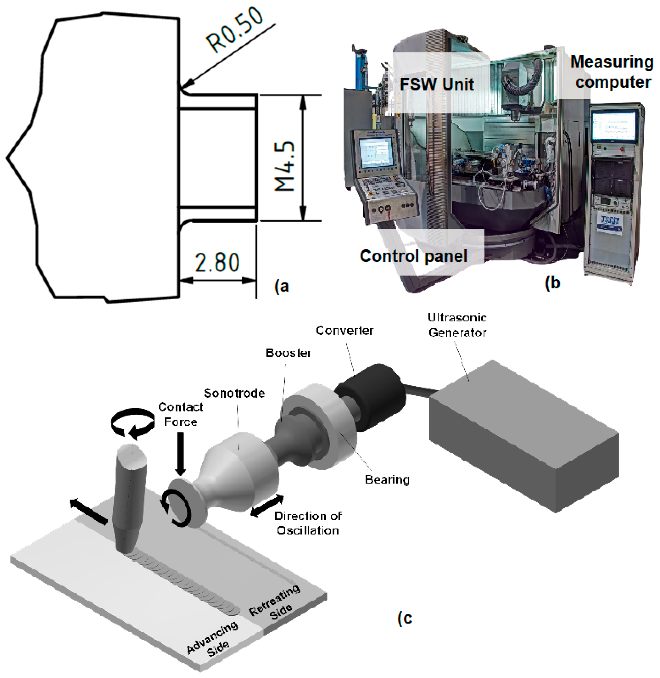
2.1. Experimental Setup and Materials
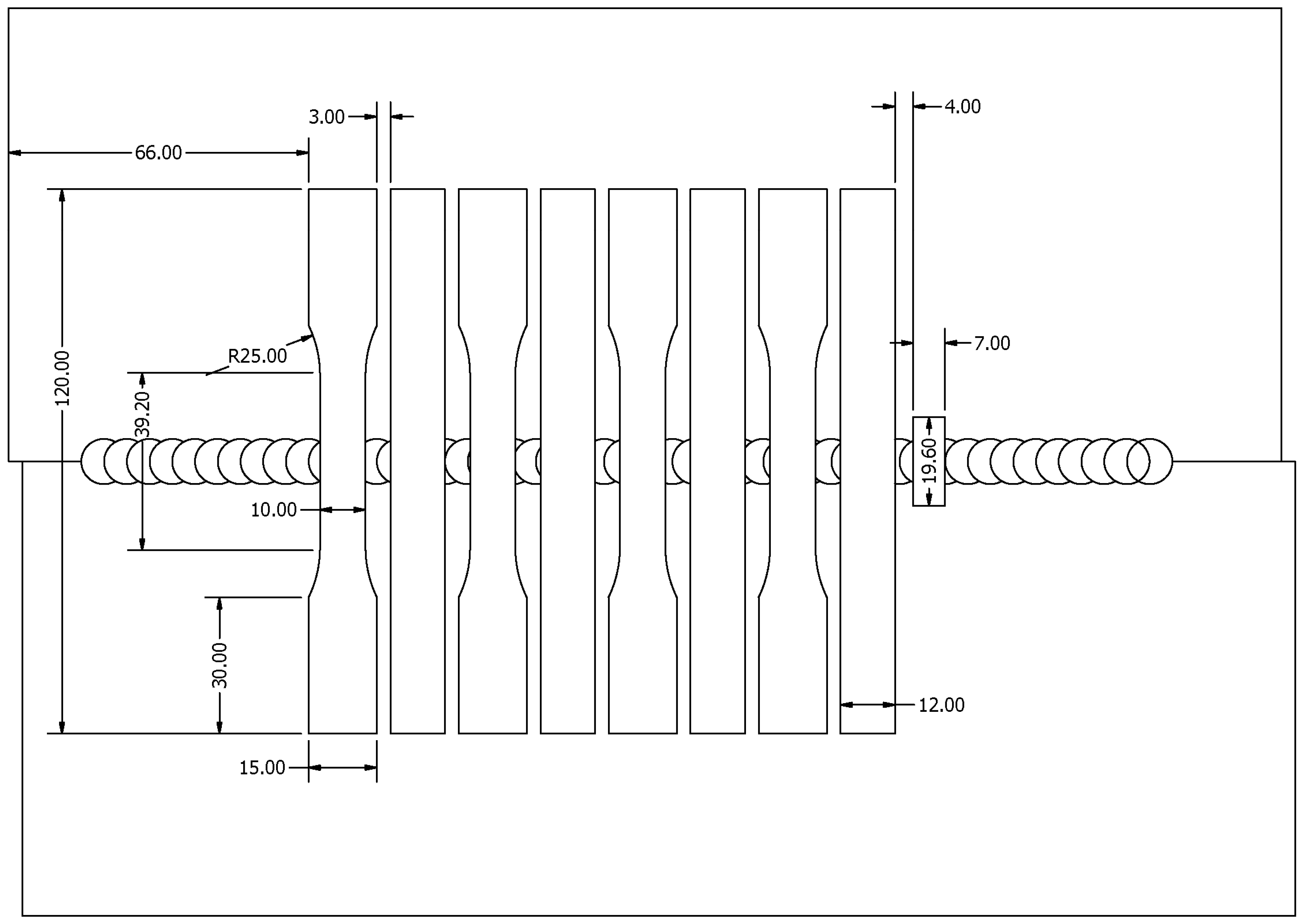
2.2. Equipment and Sample Preparation
3. Results
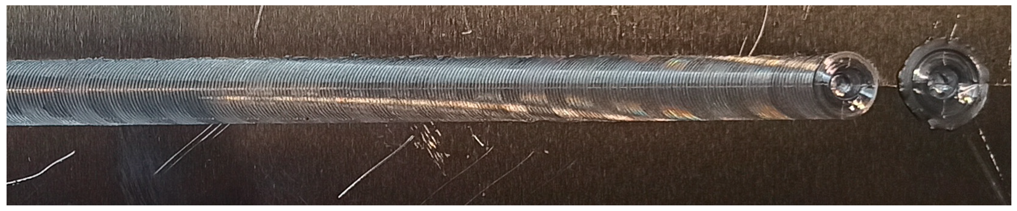
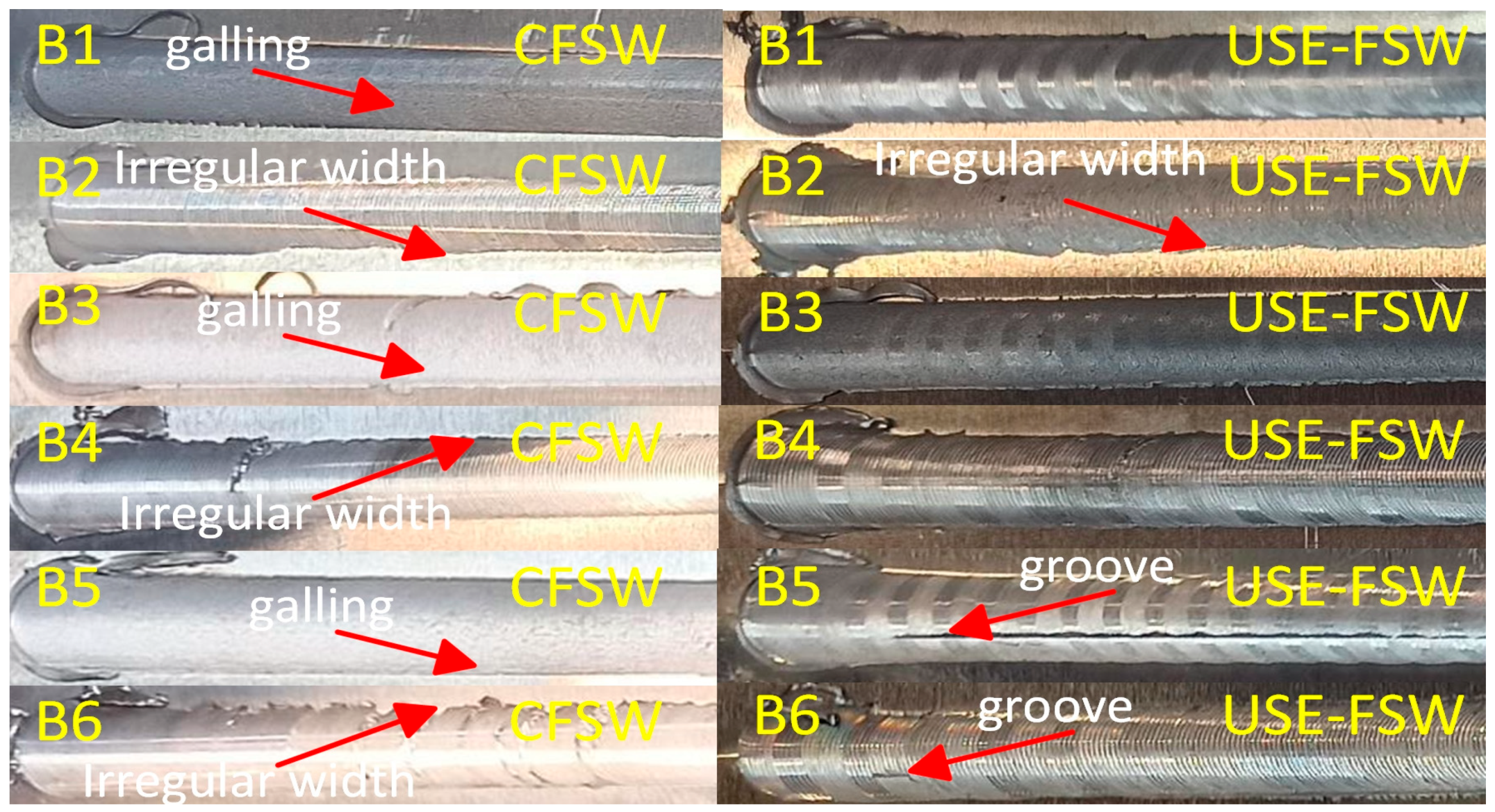
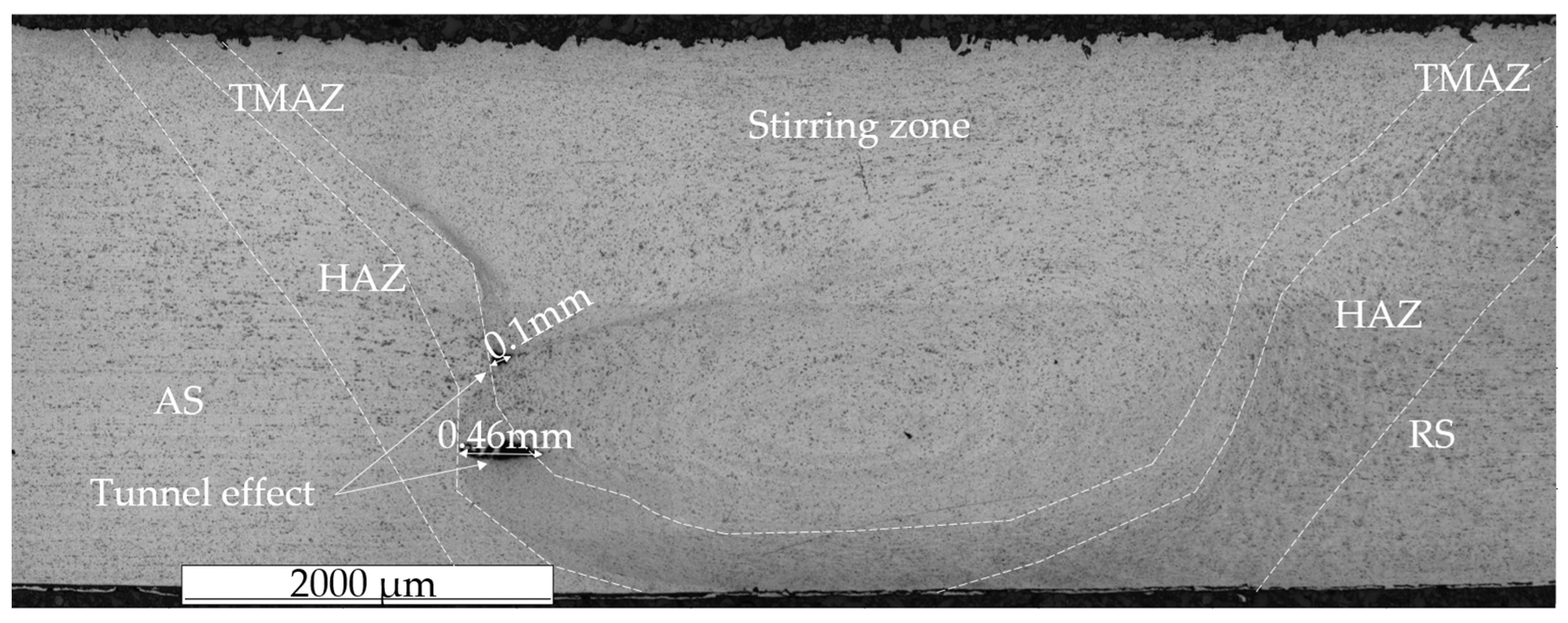
3.1. Visual Inspection
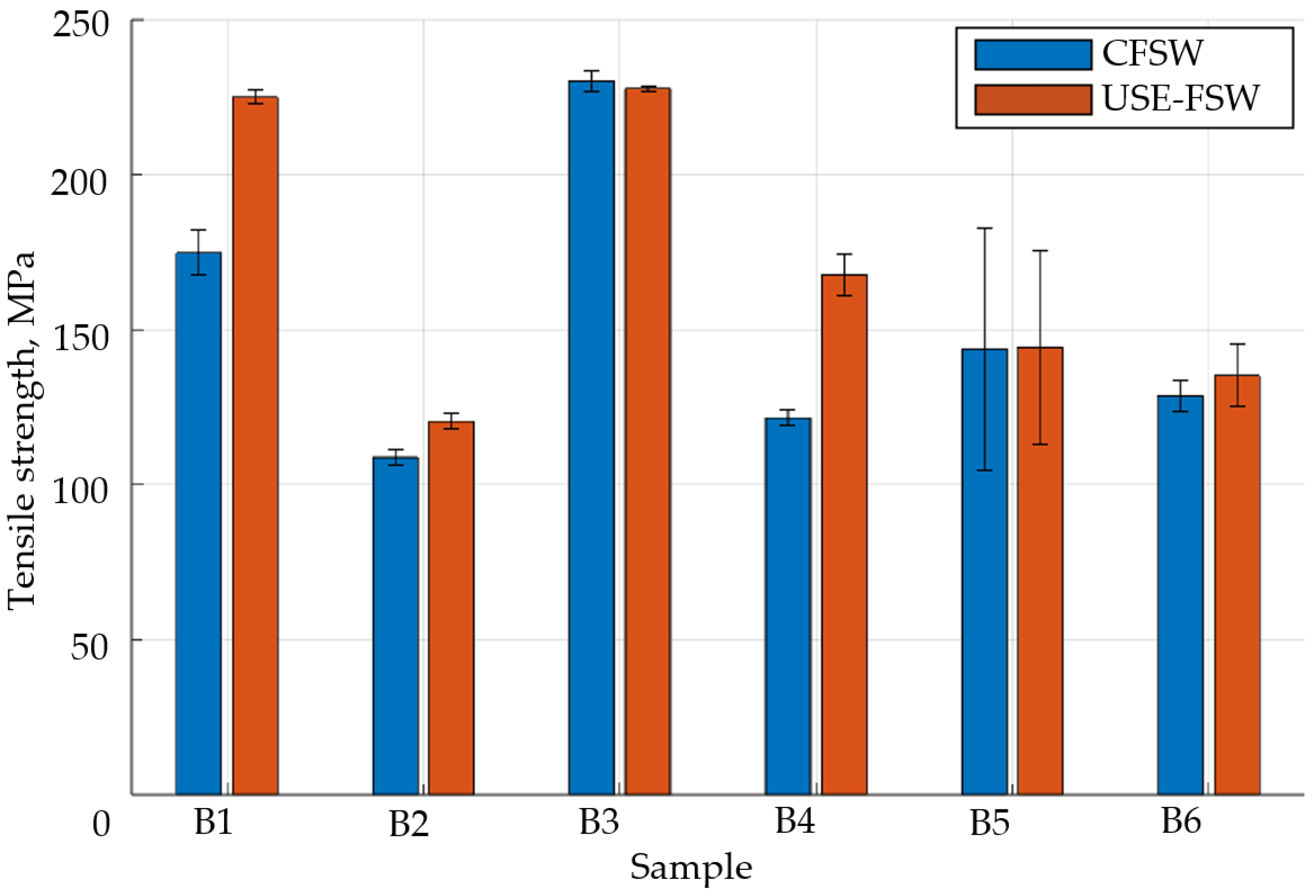
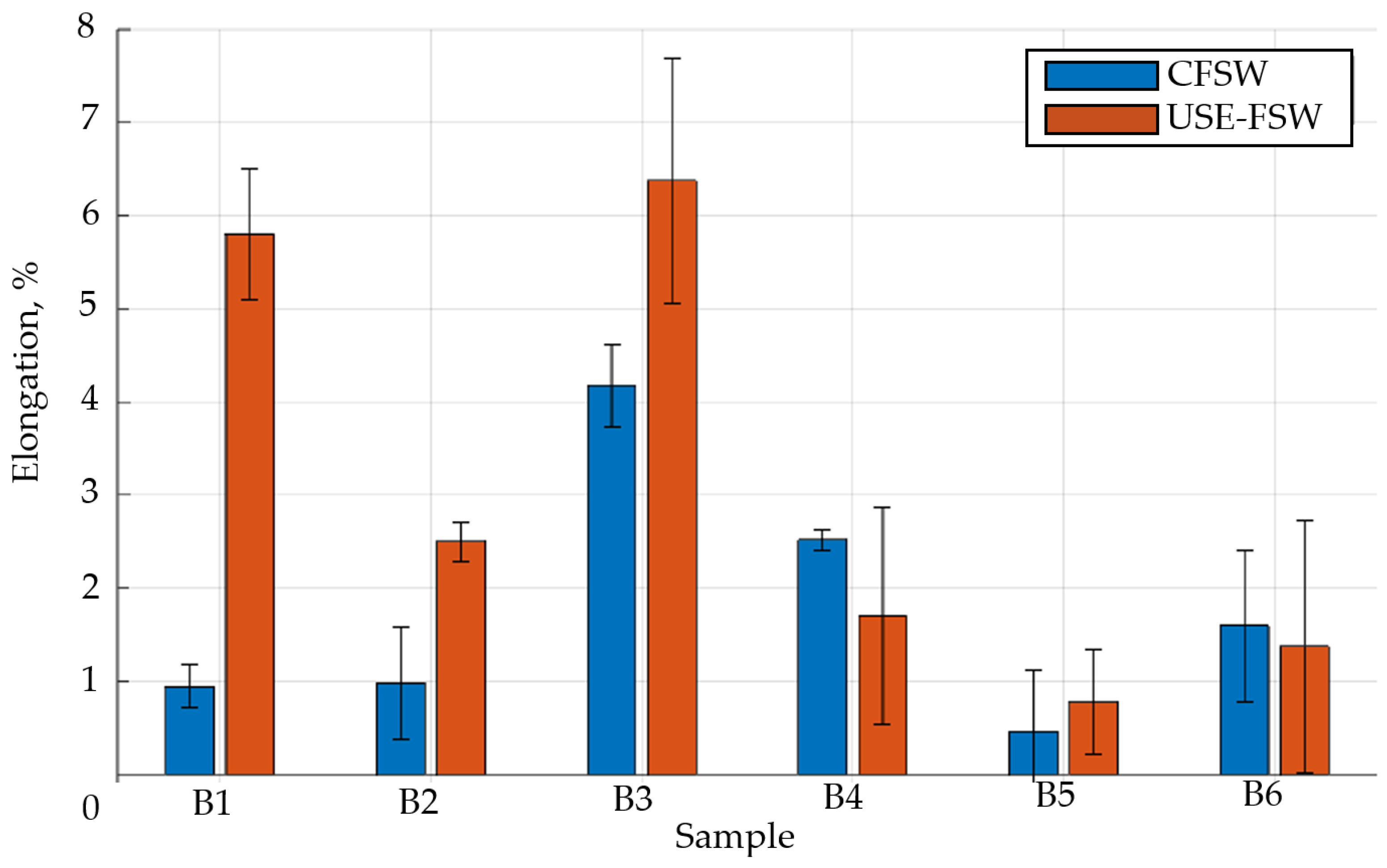
3.2. Tensile Strength
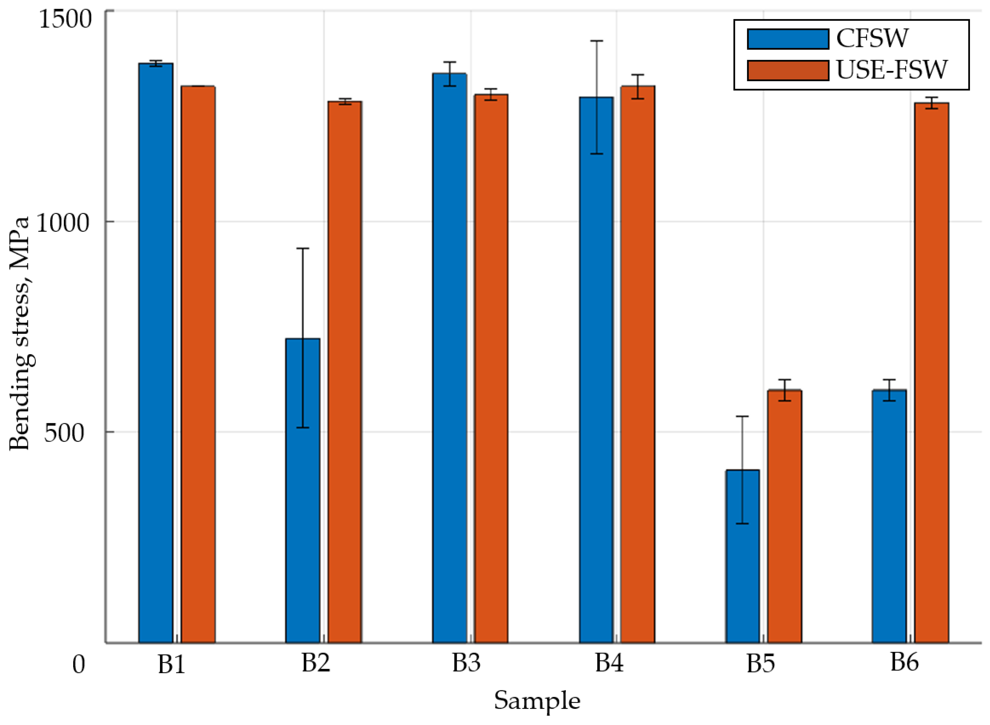
3.3. Three-Point Bending Stress
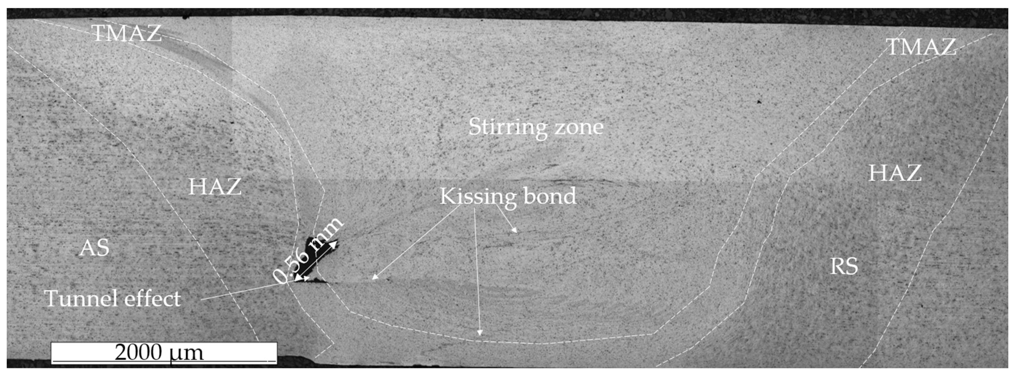
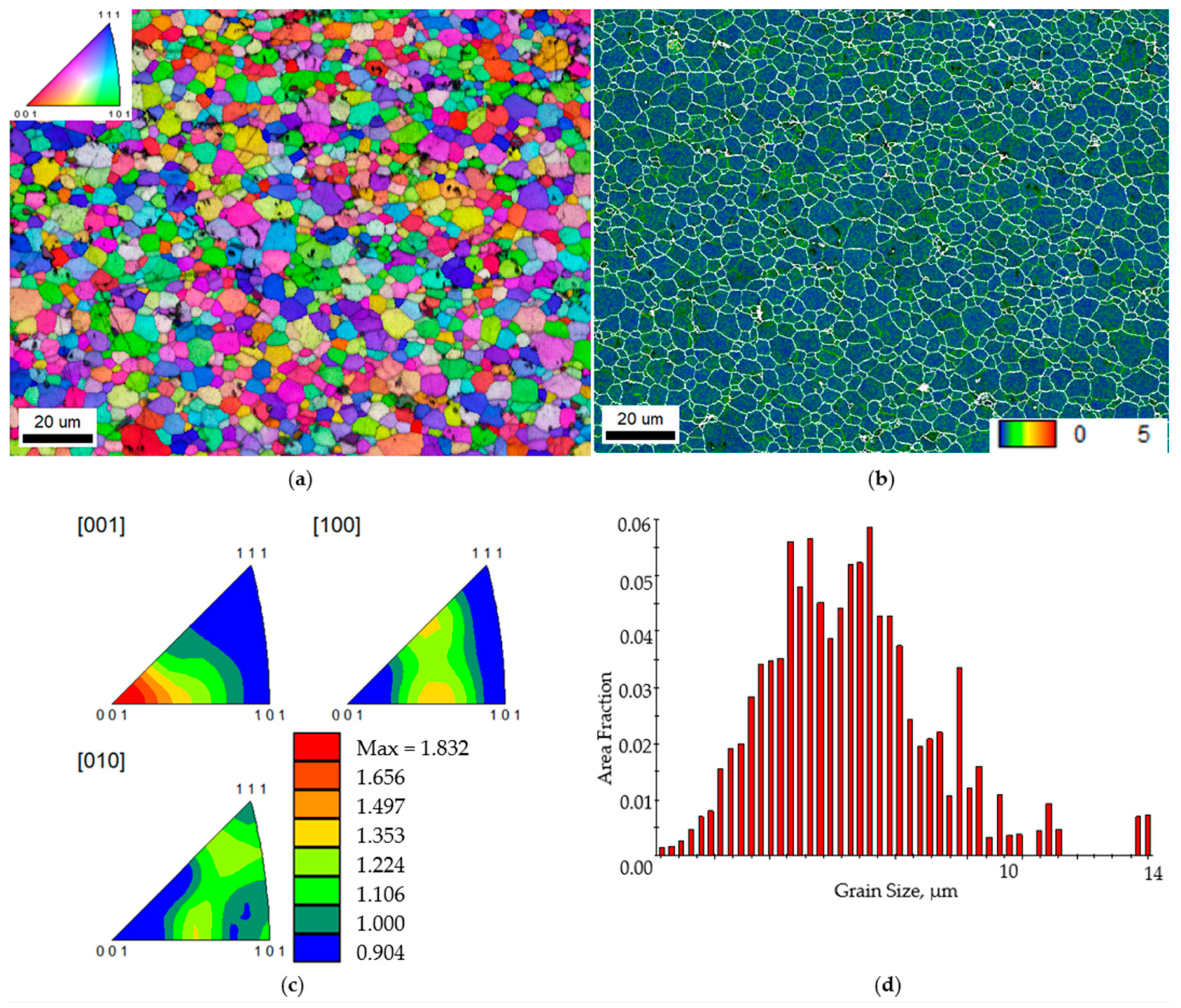
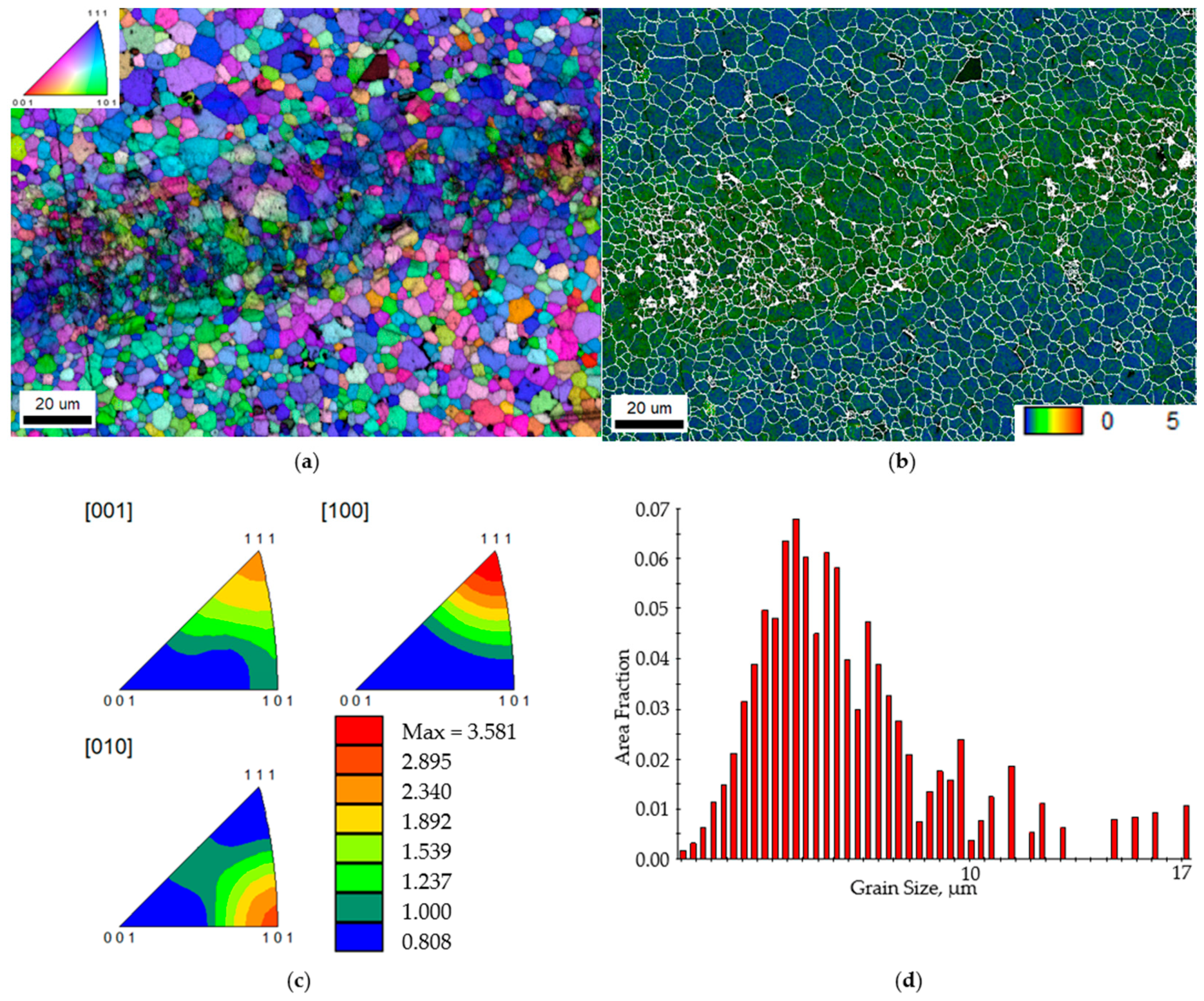
3.4. Microstructure
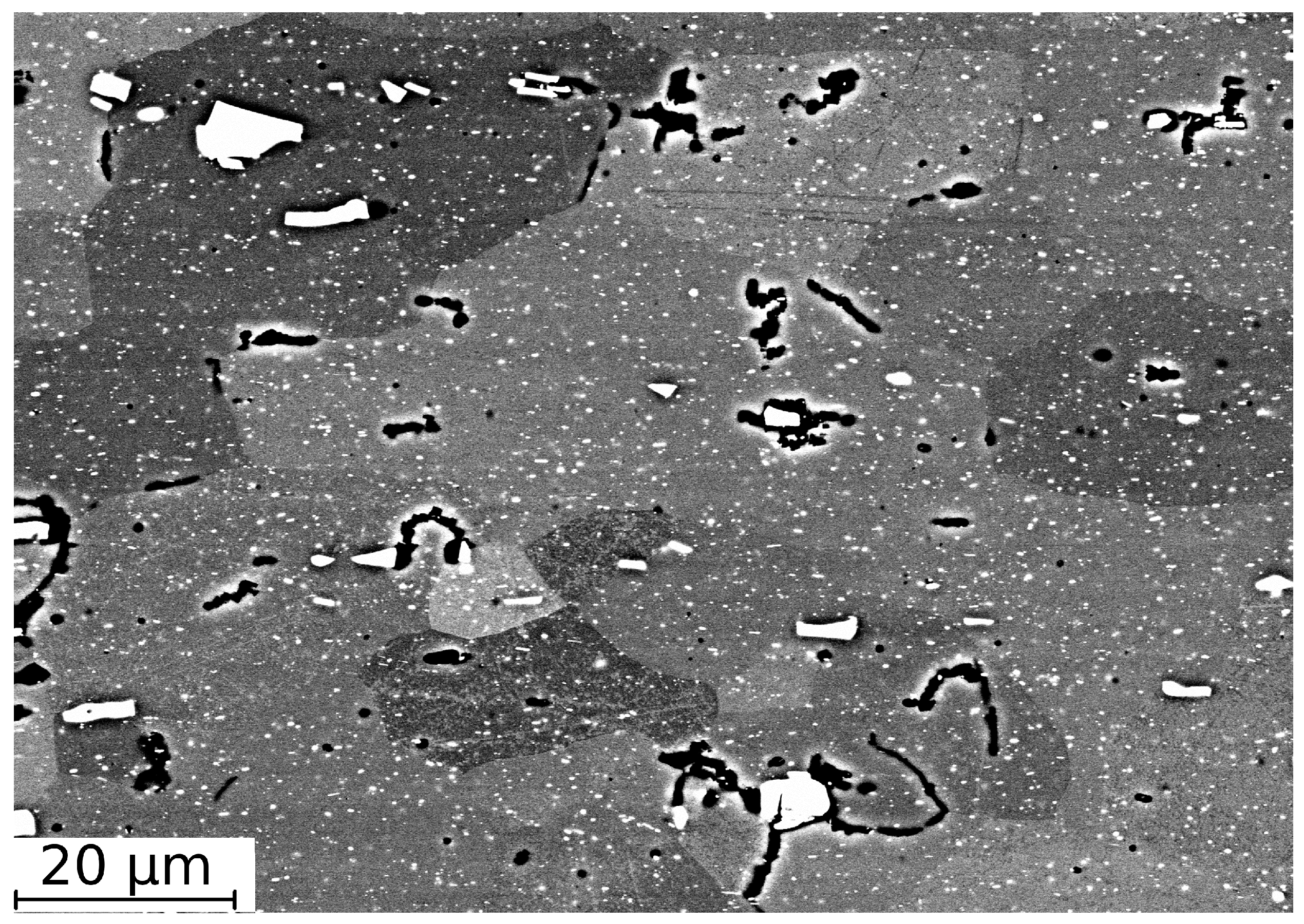
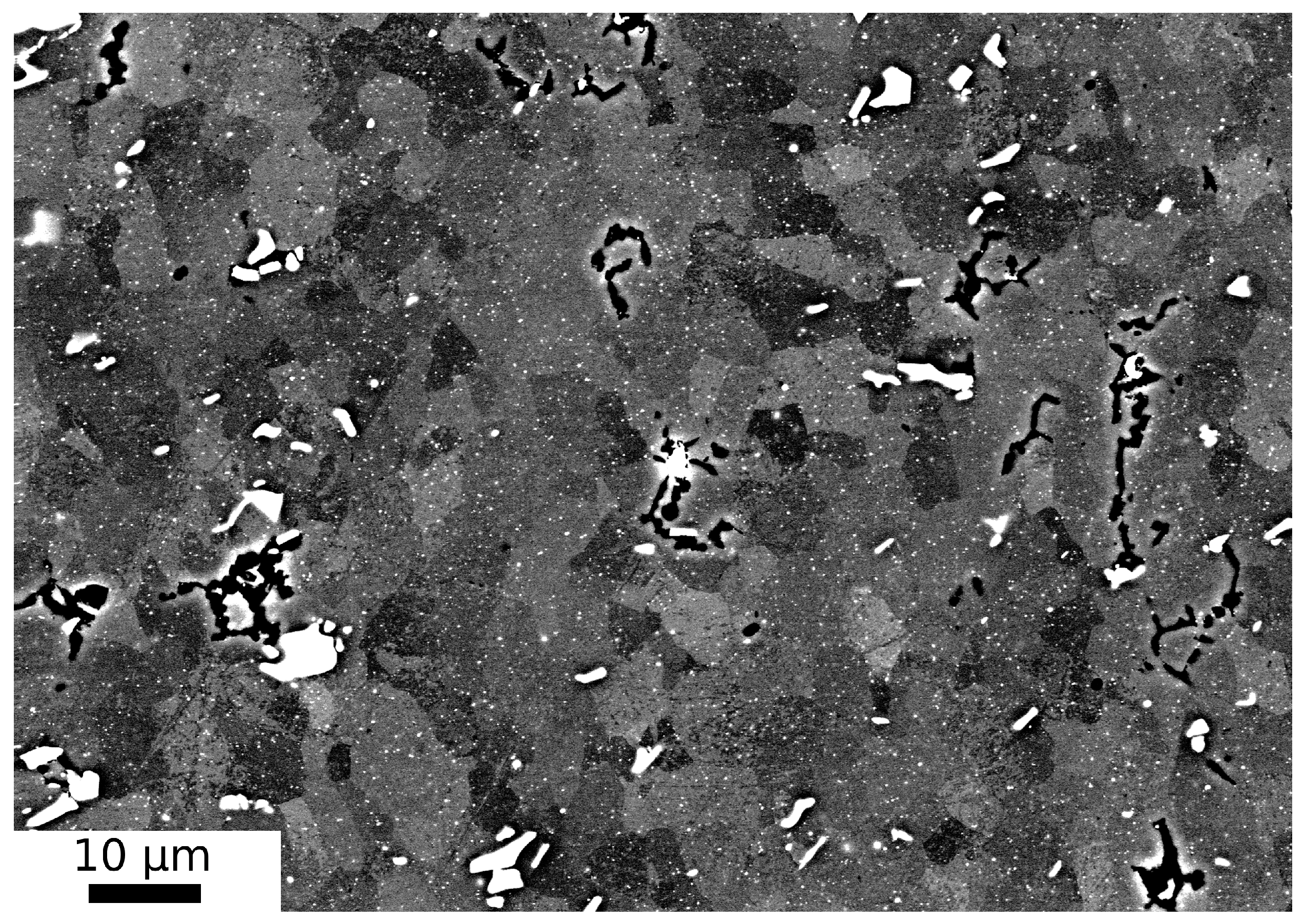
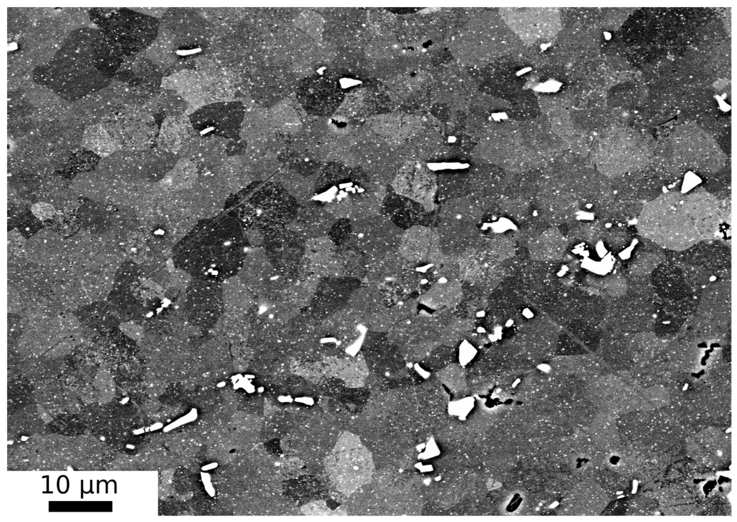
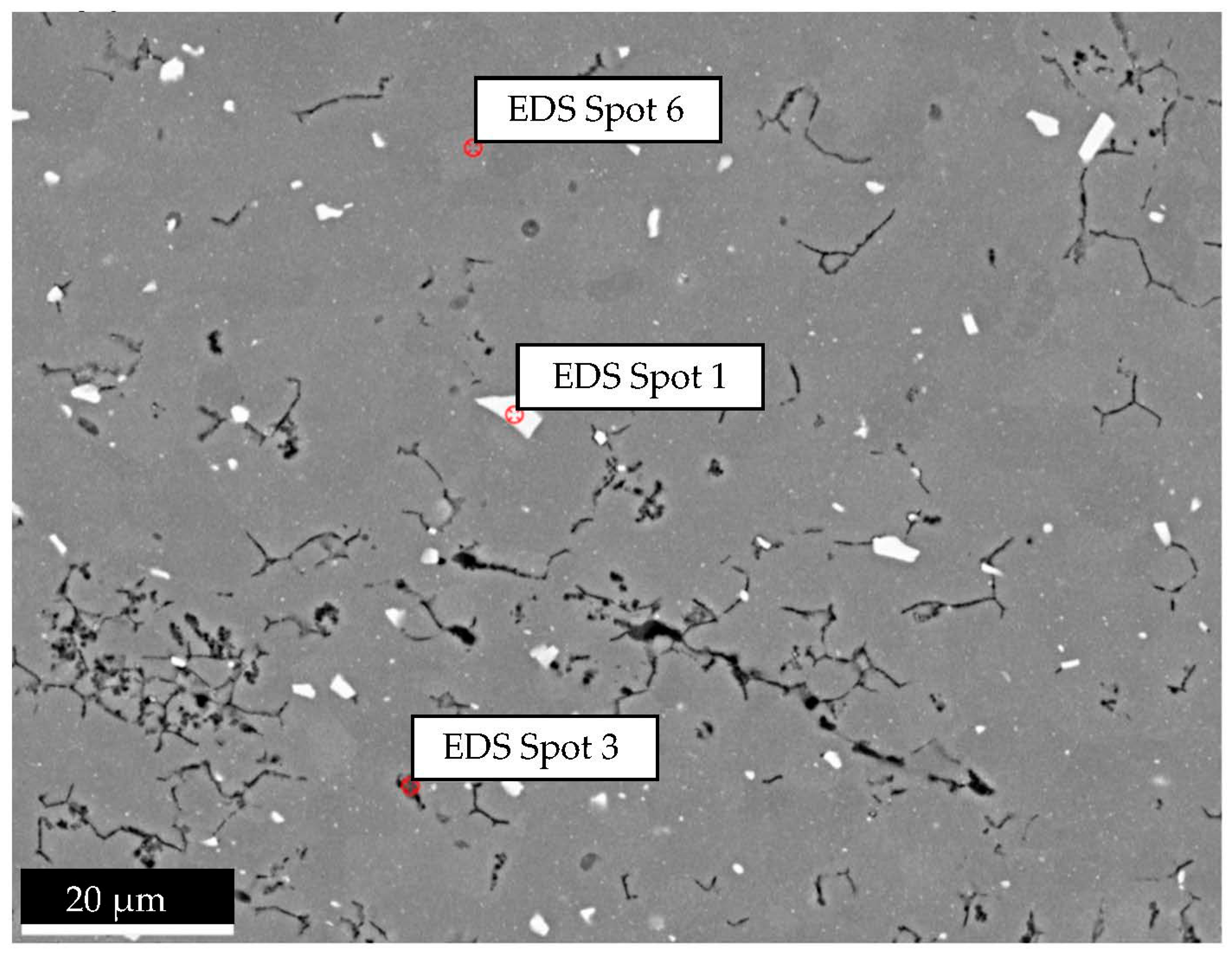
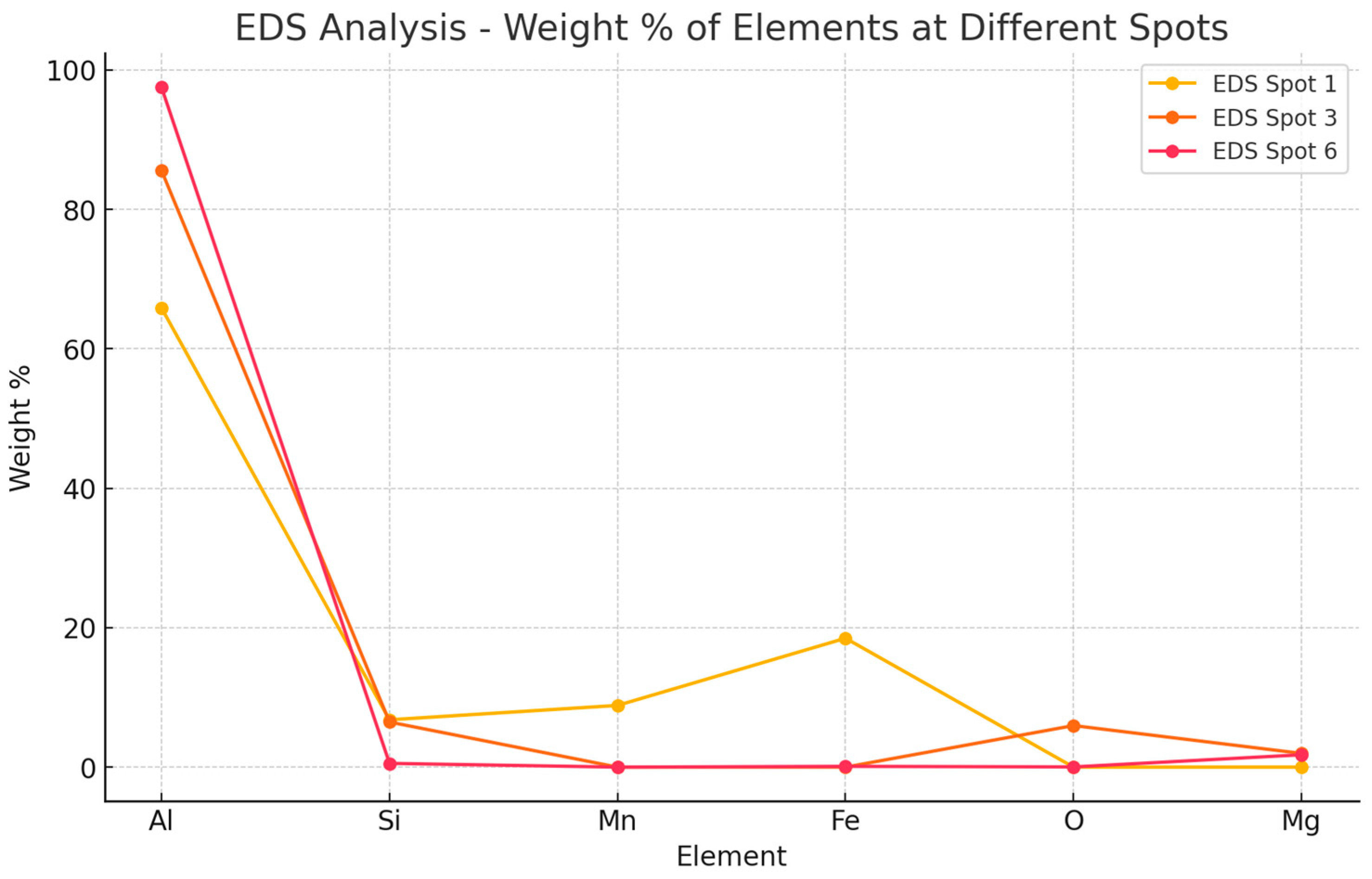
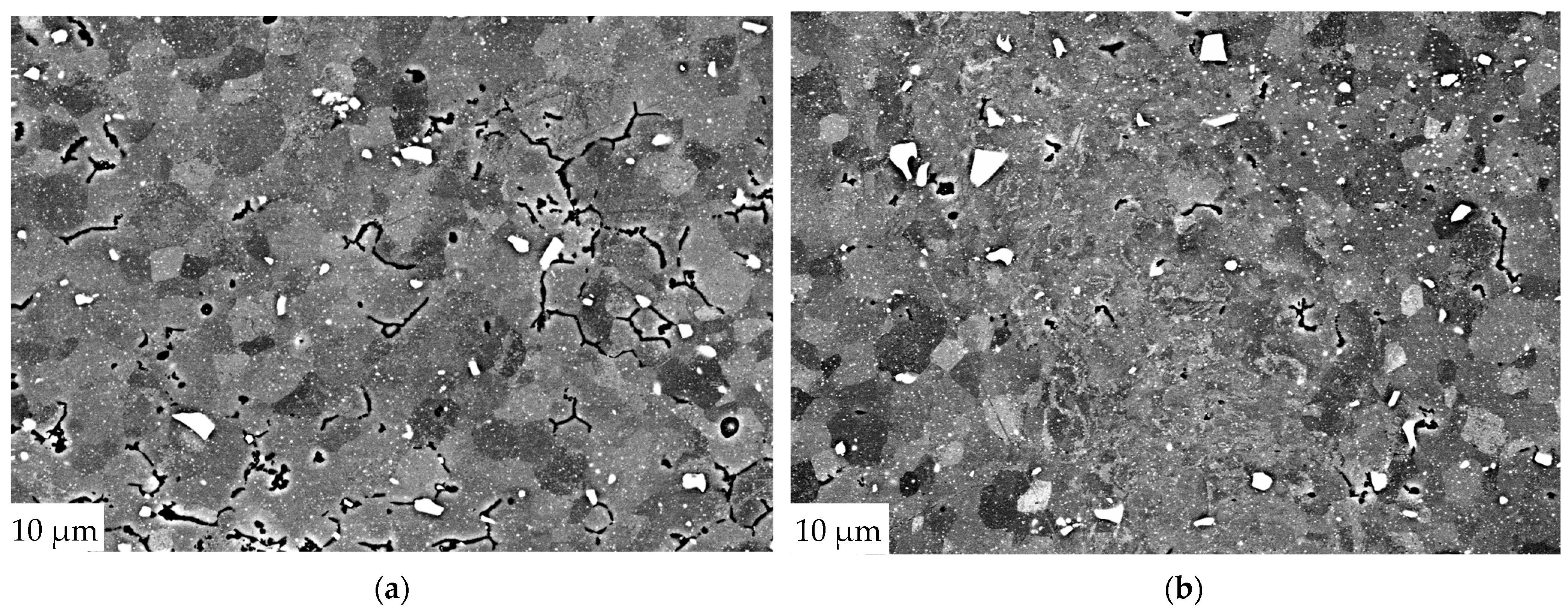
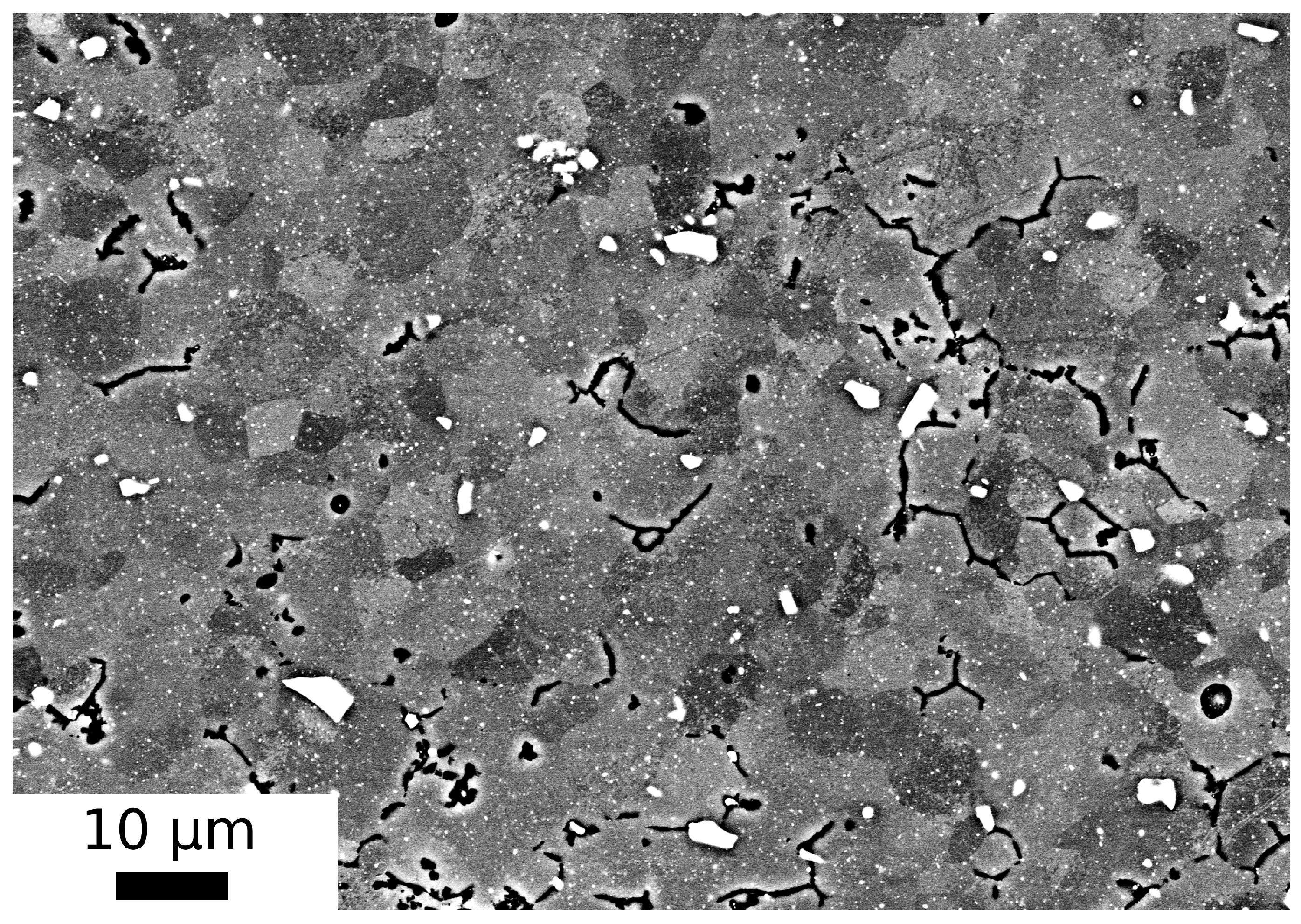
3.5. SEM Analysis
4. Discussion
4.1. Visual Inspection
4.2. Mechanical Testing
4.3. Microstructural Analysis
5. Conclusions
Author Contributions
Funding
Data Availability Statement
Acknowledgments
Conflicts of Interest
References
- Thomas, W.M.; Nicholas, E.D.; Needham, J.C.; Murch, M.G.; Temple-Smith, P.; Dawes, C.J. Friction Stir Butt Welding. GB Patent Application No. 9125978, 6 December 1991. [Google Scholar]
- Mishra, R.S.; Ma, Z.Y. Friction stir welding and processing. Mater. Sci. Eng. R Rep. 2005, 50, 1–78. [Google Scholar] [CrossRef]
- Saha, R.; Biswas, P. Current status and development of external energy-assisted friction stir welding processes: A review. Weld. World 2022, 66, 577–609. [Google Scholar] [CrossRef]
- Álvarez, A.; Cid, V.; Pena, G.; Sotelo, J.; Verdera, D. Assisted Friction Stir Welding of Carbon Steel: Use of Induction and Laser As Preheating Techniques. In Friction Stir Processing VII; TMS, Wiley: Hoboken, NJ, USA, 2013; pp. 117–127. [Google Scholar] [CrossRef]
- Vijendra, B.; Sharma, A. Induction heated tool assisted friction-stir welding (i-FSW): A novel hybrid process for joining of thermoplastics. J. Manuf. Process. 2015, 20, 234–244. [Google Scholar] [CrossRef]
- Campanelli, S.L.; Casalino, G.; Casavola, C.; Moramarco, V. Analysis and comparison of friction stir welding and laser assisted friction stir welding of aluminum alloy. Materials 2013, 6, 5923–5941. [Google Scholar] [CrossRef] [PubMed]
- Casalino, G.; Campanelli, S.; Ludovico, A.D.; Contuzzi, N.; Angelastro, A. Study of a fiber laser assisted friction stir welding process. In Proceedings of the SPIE 2012, San Francisco, CA, USA, 14 February 2012; Volume 8239, p. 823913. [Google Scholar] [CrossRef]
- Liu, X.; Lan, S.; Ni, J. Electrically assisted friction stir welding for joining Al 6061 to TRIP 780 steel. J. Mater. Process. Technol. 2015, 219, 112–123. [Google Scholar] [CrossRef]
- Luo, J.; Chen, W.; Fu, G. Hybrid-heat effects on electrical current aided friction stir welding of steel, and Al and Mg alloys. J. Mater. Process. Technol. 2014, 214, 3002–3012. [Google Scholar] [CrossRef]
- Kou, S.; Cao, G.P. Arc-Enhanced Friction Stir Welding. U.S. Patent No. 7078647, 18 July 2006. [Google Scholar]
- Bang, H.S.; Bang, H.S.; Song, H.J.; Joo, S.M. Joint properties of dissimilar Al6061-T6 aluminum alloy/Ti-6%Al-4%V titanium alloy by gas tungsten arc welding assisted hybrid friction stir welding. Mater. Des. 2013, 51, 544–551. [Google Scholar] [CrossRef]
- Xue, F.; He, D.; Zhou, H. Effect of Ultrasonic Vibration in Friction Stir Welding of 2219 Aluminum Alloy: An Effective Model for Predicting Weld Strength. Metals 2022, 12, 1101. [Google Scholar] [CrossRef]
- Hong, K.; Wang, Y.; Zhou, J.; Zhou, C.; Wang, L. Investigation on ultrasonic assisted friction stir welding of aluminum/steel dissimilar alloys. High Temp. Mater. Process. 2021, 40, 45–52. [Google Scholar] [CrossRef]
- Tan, M.; Wu, C.; Su, H. Ultrasonic effects on microstructures and mechanical properties of friction stir weld joints of dissimilar AA2024/AZ31B alloys. Weld. World 2023, 67, 373–384. [Google Scholar] [CrossRef]
- Buffa, G. Friction Stir Welding Of AA6082-T6 Sheets: Numerical Analysis And Experimental Tests. AIP Conf. Proc. 2004, 712, 1224–1229. [Google Scholar] [CrossRef]
- Thomä, M.; Wagner, G.; Straß, B.; Wolter, B.; Benfer, S.; Fürbeth, W. Ultrasound enhanced friction stir welding of aluminum and steel: Process and properties of EN AW 6061/DC04-Joints. J. Mater. Sci. Technol. 2018, 34, 163–172. [Google Scholar] [CrossRef]
- Thomä, M.; Gester, A.; Wagner, G. Comparison of process behavior, microstructure and mechanical properties of ultrasound enhanced friction stir welded titanium/titanium joints. Weld. World 2022, 66, 1131–1140. [Google Scholar] [CrossRef]
- Gemmel Metalle. Available online: https://www.gemmel-metalle.de/aluminiumhalbzeuge/flach/6082/1.html (accessed on 28 June 2024).
- EN-485:2016; Aluminum and Aluminum Alloys—Sheet, Strip and Plate. The European Committee for Standardization: Brussels, Belgium, 2016.
- Warren, A. Developments and challenges for aluminum—A Boeing perspective. Mater. Forum 2004, 28, 24–31. [Google Scholar]
- EN-573-3:2024; Aluminum and Aluminum Alloys—Chemical Composition and form of Wrought Products—Part 3: Chemical Composition and form of Products. The European Committee for Standardization: Brussels, Belgium, 2024.
- EN ISO-4957:2018; Tool Steel. The European Committee for Standardization: Brussels, Belgium, 2018.
- Thomä, M.; Gester, A.; Wagner, G.; Straß, B.; Wolter, B.; Benfer, S.; Gowda, D.K.; Füberth, W. Application of the hybrid process ultrasound enhanced friction stir welding on dissimilar aluminum/dual-phase steel and aluminum/magnesium joints. Mater. Sci. Eng. Technol. 2019, 50, 893–912. [Google Scholar] [CrossRef]
- ISO 6892-1:2019; Metallic Materials—Tensile Testing—Part 1: Method of Test at Room Temperature. The European Committee for Standardization: Brussels, Belgium, 2019.
- DIN 50125; Testing of Metallic Materials—Tensile Test Pieces. Deutsches Institut für Normung: Berlin, Germany, 2022.
- EN ISO 5173:2023; Destructive Tests on Welds in Metallic Materials. Bend Tests. The European Committee for Standardization: Brussels, Belgium, 2023.
- Gester, A.; Ozherelkov, D.; Wagner, G. Morphological Evolution of Single-Core Multi-Strand Wires during Ultrasonic Metal Welding. Metals 2024, 14, 362. [Google Scholar] [CrossRef]
- EL-Wazery, M.S.; Mabrouk, O.M.; Khafagy, S.M.; El-sissy, A.R. Mechanical and Microstructural Evaluation of AA6082-T61 Joints Produced by Ultrasonic Vibration Assisted Friction Stir Welding Process. Int. J. Eng. 2022, 35, 2297–2304. [Google Scholar] [CrossRef]
- ISO 25239-4:2020; Friction Stir Welding—Aluminium—Part 4: Specification and Qualification of Welding Procedures. The European Committee for Standardization: Brussels, Belgium, 2020.
- Edwards, P.; Ramulu, M. Investigation of microstructure, surface and subsurface characteristics in titanium alloy friction stir welds of varied thicknesses. Weld. Join. Sci. Technol. 2009, 14, 476–483. [Google Scholar] [CrossRef]
- Hussein, S.A.; Thiru, S.; Izamshah, R.; Md Tahir, A.S. Unstable temperature distribution in friction stir welding. Adv. Mater. Sci. Eng. 2014, 2, 8. [Google Scholar] [CrossRef]
- Lader, S.K.; Baruah, M.; Ballav, R.; Bag, S. Recent Developments in Friction Stir Welding Tools for Weld Bead Defects Minimization—A Review. Soldag. Insp. 2023, 28. [Google Scholar] [CrossRef]
- Zhou, N.; Song, D.; Qi, W.; Li, X.; Zou, J.; Attalah, M.M. Influence of the kissing bond on the mechanical properties and fracture behaviour of AA5083-H112 friction stir welds. Mater. Sci. Eng. A 2018, 719, 12–20. [Google Scholar] [CrossRef]
- Zhao, Y.; Wang, X.; Liu, J.; Zhang, H. Influence of ultrasonic vibration on microstructure evolution during friction stir welding of aluminum alloy. J. Mater. Process. Technol. 2024, 319, 118579. [Google Scholar] [CrossRef]
- Li, W.; Chen, Y.; Zhang, Z.; Wu, S. Effect of ultrasonic-assisted friction stir welding on grain refinement and texture formation in aluminum alloys. J. Mater. Process. Technol. 2019, 271, 168–178. [Google Scholar] [CrossRef]
- Li, X.; Zhang, D.; Wang, H.; Liu, Y.; Zhang, X. Enhancement of mechanical properties in heat-treatable aluminum alloys via ultrasonic-assisted friction stir welding. J. Alloys Compd. 2019, 803, 123–131. [Google Scholar] [CrossRef]
- Zhang, Y.; Huang, L.; Liu, C. Strengthening mechanisms in ultrasonic-assisted welding of aluminum alloys. J. Mater. Sci. Technol. 2024, 35, 1599–1607. [Google Scholar] [CrossRef]
- Sprigode, T.; Gester, A.; Guntram, W. Realization of Friction Stir Welding of Aluminum Alloy AA5754 Using a Ceramic Tool. Metals 2024, 14, 1089. [Google Scholar] [CrossRef]


| Al (%) | Cr (%) | Cu (%) | Fe (%) | Mg (%) | Mn (%) | Si (%) | Ti (%) | Zn (%) | Other (%) |
|---|---|---|---|---|---|---|---|---|---|
| 95.2–98.3 | ≤0.25 | ≤0.1 | ≤0.5 | 0.6–1.2 | 0.4–1.0 | 0.7–1.3 | ≤0.1 | ≤0.2 | ≤0.15 |
| C (%) | Si (%) | Mn (%) | P (%) | S (%) | Cr (%) | Mo (%) | V (%) | Fe (%) |
|---|---|---|---|---|---|---|---|---|
| 0.35–0.42 | 0.8–1.2 | 0.25–0.5 | <0.03 | <0.02 | 4.8–5.5 | 1.2–1.5 | 0.85–1.15 | Balance |
| Sample | Rotational Speed (rpm) | Welding Speed (mm/min) | Tilt (°) | Amplitude (µm) |
|---|---|---|---|---|
| B1 | 2800 | 250 | 0.5 | Without and with 7.6 (Work time 66.7%) |
| B2 | 800 | 400 | 0.5 | |
| B3 | 2800 | 250 | 1.5 | |
| B4 | 800 | 400 | 1.5 | |
| B5 | 2800 | 250 | 2.5 | |
| B6 | 800 | 400 | 2.5 |
| Rolling Direction | Rmax (MPa) | R0.2 (MPa) | A (%) |
|---|---|---|---|
| || | 329.1 ± 1.61 | 278.2 ± 1.33 | 16.53 ± 0.87 |
| ⊥ | 333.2 ± 1.17 | 281 ± 1.50 | 18.9 ± 2.28 |
| Rolling Direction | Rmax (MPa) | ΔL at Rmax (mm) |
|---|---|---|
| || | 1280.63 ± 31.12 | 38.50 ± 3.2 |
| ⟂ | 1089.13 ± 70.45 | 35.83 ± 1.48 |
Disclaimer/Publisher’s Note: The statements, opinions and data contained in all publications are solely those of the individual author(s) and contributor(s) and not of MDPI and/or the editor(s). MDPI and/or the editor(s) disclaim responsibility for any injury to people or property resulting from any ideas, methods, instructions or products referred to in the content. |
© 2024 by the authors. Licensee MDPI, Basel, Switzerland. This article is an open access article distributed under the terms and conditions of the Creative Commons Attribution (CC BY) license (https://creativecommons.org/licenses/by/4.0/).
Share and Cite
Rebrin, M.; Gester, A.; Ozherelkov, D.; Wächtler, C.; Sprigode, T.; Mädlow, M.; Wagner, G. Ultrasound-Enhanced Friction Stir Welding of Aluminum Alloy 6082: Advancements in Mechanical Properties and Microstructural Refinement. Metals 2024, 14, 1241. https://doi.org/10.3390/met14111241
Rebrin M, Gester A, Ozherelkov D, Wächtler C, Sprigode T, Mädlow M, Wagner G. Ultrasound-Enhanced Friction Stir Welding of Aluminum Alloy 6082: Advancements in Mechanical Properties and Microstructural Refinement. Metals. 2024; 14(11):1241. https://doi.org/10.3390/met14111241
Chicago/Turabian StyleRebrin, Marat, Andreas Gester, Dmitrii Ozherelkov, Christiane Wächtler, Toni Sprigode, Martin Mädlow, and Guntram Wagner. 2024. "Ultrasound-Enhanced Friction Stir Welding of Aluminum Alloy 6082: Advancements in Mechanical Properties and Microstructural Refinement" Metals 14, no. 11: 1241. https://doi.org/10.3390/met14111241
APA StyleRebrin, M., Gester, A., Ozherelkov, D., Wächtler, C., Sprigode, T., Mädlow, M., & Wagner, G. (2024). Ultrasound-Enhanced Friction Stir Welding of Aluminum Alloy 6082: Advancements in Mechanical Properties and Microstructural Refinement. Metals, 14(11), 1241. https://doi.org/10.3390/met14111241