1. Introduction
Burnishing is one of the methods of finishing metals and their alloys, sinters and plastics, which involves the use of local plastic deformation [
1,
2,
3], generated in the surface layer of the object [
4,
5,
6,
7,
8,
9], as a result of specific (force and kinematic) interaction of hard and a smooth tool (in the shape of a ball, disc, roller or other) with a machined surface [
10,
11,
12,
13,
14,
15,
16,
17,
18]. The surface state and quality after previous treatment significantly depend on its quality after previous treatment [
15,
16,
17,
18,
19].
The literature review shows that there are many works in the field of burnishing treatment. In the paper [
1,
2], low-plasticity burnishing and its applications were analyzed and the information on how low-plasticity burnishing strengthens the material surface and thereby influences the mechanical performance, including the surface quality, residual stress, microstructure, microhardness, fatigue and wear performance, are presented.
In the burnishing process, an important process feature is the degree of cold rolling of the material, where the resistance of the element to fatigue loads only increases to a certain level with increasing degree of cold rolling. The introduction of additional stresses in the elements reduces the fatigue strength of this element in service, and these additional stresses should be taken into account when planning the degree of cold rolling value [
3,
4]. In some works, the parameters of the surface after previous treatment and then the results after burnishing are presented, but very often, they only take into account roughness parameters. In paper [
4], the structure of the surface after burnishing and turning was analyzed, taking into account roughness parameters, as well as the photographs of the specimen surface and the bearing area curve. The steel products with alloy and composite coatings based on nickel with numerical and experimental tests of the plastic processing of alloy coatings were carried out in [
5] and showed that after burnishing, the roughness was reduced to 1/12 and the alloy coatings were strengthened by 25%.
Skoczylas et al. [
6,
7] report the results of experimental studies on the impact of ball burnishing parameters on the roughness, microstructure and microhardness of the surface layer of laser-cut C45 steel parts. They also analyzed the distribution of residual stresses generated in the surface layer of these parts. Ball burnishing is a widely used method by researchers [
6,
7,
8,
9,
12,
15].
A three-dimensional numerical finite element model of the ball burnishing process, including real surface integrity descriptors resulting from a ball-end milled AISI 1038 surface in the target workpiece, was presented in [
8]. They presented that the resulting topology and residual stresses are independent of the burnishing direction, but model outputs are highly influenced by the value of the coefficient of friction. The effects of an ultrasonic-vibration-assisted ball burnishing process on the topological descriptors of nickel-based alloy Udimet R 720 are presented in [
9] while taking into account the topology changes after ultrasonic-assisted ball burnishing and the influence of the burnishing conditions. In the paper, the authors assess that the burnishing preload and the number of passes are the only influential factors on surface change, whereas the feed velocity of the tool and the strategy are not relevant to the result. Jordi Llumà et al. proved that an increase in burnishing preload diminishes the ductile behavior of the material and increases its strength representative values, although the proportion of affected material in the cross-section of the specimen is reduced with regard to the whole surface. The influence of multiple passes and directions on the produced surface of soft and rough ground-prepared brass was recommended by Alaskari [
10]. The surface after-slide burnishing parameters on the surface roughness of shafts were tested using the artificial neural networks with the best regression statistics, which predicted an average surface roughness of the shafts with R
2 = 0.987 [
11]. Slavov [
12,
13] carried out an experimental investigation of the fatigue durability of AISI 304 and AISI 316L austenitic stainless steels, which have regular reliefs, finding that when the deforming force, the amplitude of the sinewaves and their wavenumber is set at high values, and the feed rate is set at its low value, the probability of reaching maximum fatigue life for the parts made of AISI 304 or 316L is equal to 97% [
12] and the fatigue life of researched steel is increased when directions of pre-rolled plastic deformation and the tool movement during ball burnishing are coincident [
13]. The dependence of the depth of the plastically deformed surface layer was determined for a given pressure force and variable braking moments in the paper [
14]. The ball burnishing significantly enhances the finish of the parts despite requiring the use of solvents or provoking dimensional changes to the parts, which is presented using SEM analysis [
15,
16]. It also caused decreases in the friction force and volumetric wear of up to 45% in comparison to sliding pairs containing milled discs [
17,
19]. Aluminum matrix composites (AMCs) were analyzed [
20] by applying different contact forces and feeds and roller bodies manufactured from cemented carbide. Roller burnishing enables the generation of smooth surfaces [
17,
18,
19,
20,
21,
22,
23] with strong compressive residual stresses [
18,
19,
20,
21,
23,
24]. That is why burnishing rolling is also very often taken into account in numerical analyses [
22,
23,
24,
25,
26,
27]. More often, analysis of the burnishing parameters and their influence on the surface integrity of Ti-6Al-4V [
22] or AISI 4130 alloy steel [
23] are presented. Kukiełka [
26,
27,
28,
29] stated that the kinematics of the smoothing of the asperities depends only on the vertical angle of the rough surface and determines the angle boundaries for which there is a change in the flow mechanism.
Kuznietsova [
30] has presented numerical and physical modeling of nanostructuring burnishing to reveal the limiting values of process parameters, which serve both to provide the appropriate surface quality and positive deformation-induced structural modification of the subsurface layers as well as to avoid shear instability in the subsurface layers of burnished metal. Reference [
30] presents the effects of load, burnishing speed, tooltip material, tool pass number and tribological transfer on the burnished surface roughness, which have been elucidated by the example of quenched and tempered steels 20X (EN 20Cr4) and 20X13 (EN X20Cr13 or 1.4021). The paper [
31] presents preliminary studies of a new innovative surface treatment method—the process of roller burnishing of macro-asperities of the surface. The possibility of plastic shaping of the surface macrostructure with indentations (plateau structure), which will show anti-wear properties through appropriate surface shaping and the compressive stress state in the product’s top layer, was conducted, and the main goal of the work was to develop adequate methods and mathematical models to enable the design of the macro-asperities of the surface burnishing process to maintain the dimensional tolerance of the shaped parts. Therefore, the vertical angle of surface asperities after the turning process is another parameter influencing the geometric structure of the surface and the value of the roughness parameters of the burnished surface. This makes it possible to select turning and burnishing conditions in order to obtain a product with the required geometric structure due to the intended use of the product. As the analysis of literature shows, despite the large number of works on burnishing, the surface characteristics taking into account macro-asperities as well as characteristics of microstructure (sub-asperities) have not been considered.
The paper presents the results of experimental research and surface characteristics after the process of roller burnishing macro-asperities of the surface. As part of the work, the possibility of plastic shaping of the surface macrostructure with indentations (plateau structure), which will show anti-wear properties through appropriate surface shaping and the compressive stress state in the product’s top layer, was investigated. The essence of the paper is to present the analysis of the surface roughness parameters and carry out an analysis of SEM, AFM and metallographic results for the burnished surface. The main objective of the work is to develop an adequate outline of the surface to receive the required parameters and characteristics of the surface after burnishing. The results of dependencies of roughness parameter after turning and after burnishing from the vertical angle of asperities are presented, as well as SEM, AFM and metallographic analysis for the surface with a vertical angle of 60 ÷ 150 degrees.
2. Materials and Methods
The tests were carried out on C45 steel samples, which is the most commonly used non-alloy steel for heat treatment, suitable for surface treatment and hardening. It is delivered in an annealed state with high ductility, is easy to process and has good shape stability after heat treatment (slight over-hardening should be taken into account). The tensile strength of the material used for testing was σ
u = 508 MPa, the hardness in the softly annealed state was 227.5 HB, the yield point σ
y = 425 MPa, the breaking stress was σ
f = 533 MPa, the relative elongation A
5 = 14.41% and the relative narrowing Z = 21%, samples diameter d = 24.3 mm. Steel is used in the construction of machines for crucial elements. It is especially intended for heat-treated parts, making the most of its mechanical properties. The chemical composition was determined, and the results are presented in
Table 1.
In order to determine the influence of the vertex angle of the roughness on the quality of the surface obtained as a result of burnishing, samples that were characterized by a determined outline of the surface roughness were prepared. In the first phase, the samples were turned to a diameter of 24.3 mm at turning speed v
t = 0.7 m·s
−1 and feed f = 0.04 mm·rev
−1. Then, the shafts were finished and turned with knives with different blade geometries in order to obtain asperities with the vertex angles in the range θ = 60 ÷ 150°, changing the angle every 15°. Final turning was carried out with a feed of f = 1 mm·rev
−1 and a speed of v
t = 0.44 m·s
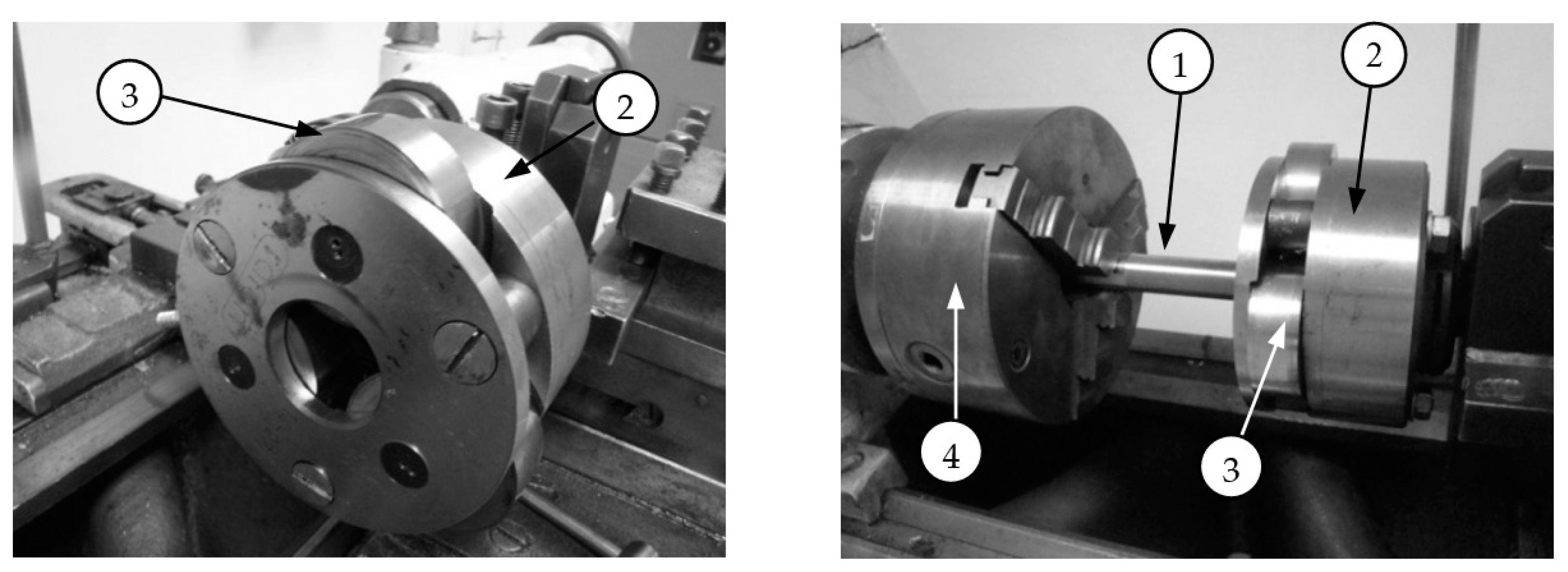
−1. The asperities with a constant s = 1 mm spacing were obtained. The tests were repeated three times. After both the turning and burnishing processes, the samples were profiled and measured to assess their dimensional and shape accuracy using a Dynascope Kestrel optical microscope with a five-fold magnification lens. Then, the surfaces of the samples were burnished on a station consisting of a TUB 32 lathe with a three-roller head with a rigid clamp and discs with a two-toroidal cylindrical outline, manufactured by Rafan NUGh 14–27 (
Figure 1).
The burnishing feed was equal to the feed of the preceding machining, and the burnishing speed was The burnishing depth depended on the height of the asperities, but the aim of the process was to completely smooth the surface in one pass of the burnishing head. Even though the rollers were made in the same accuracy class, it was necessary to correct the settings of the discs in the burnishing head. This was influenced by the method of mounting the shaft to the head, friction and decohesion in the machining zone, and random dynamic phenomena—vibrations.
Parameters of surface roughness after turning and after burnishing were obtained by testing samples with the contact profilometer Hommel Tester T8000 (HommelWerke, Konstanz, Germany).
The NT 206 atomic force microscope was used to analyze the surface nanoroughness. Measurements were made in contact mode at the center of the crushed asperity and provided information on the surface roughness at the nanoscale. The measurement itself involves imaging the sample surface using a probe (e.g., a blade mounted on a spring), the tip of which has dimensions below 0.1 nm. Topography is measured by the van der Waals attractive-repulsive forces that arise between the probe and the sample.
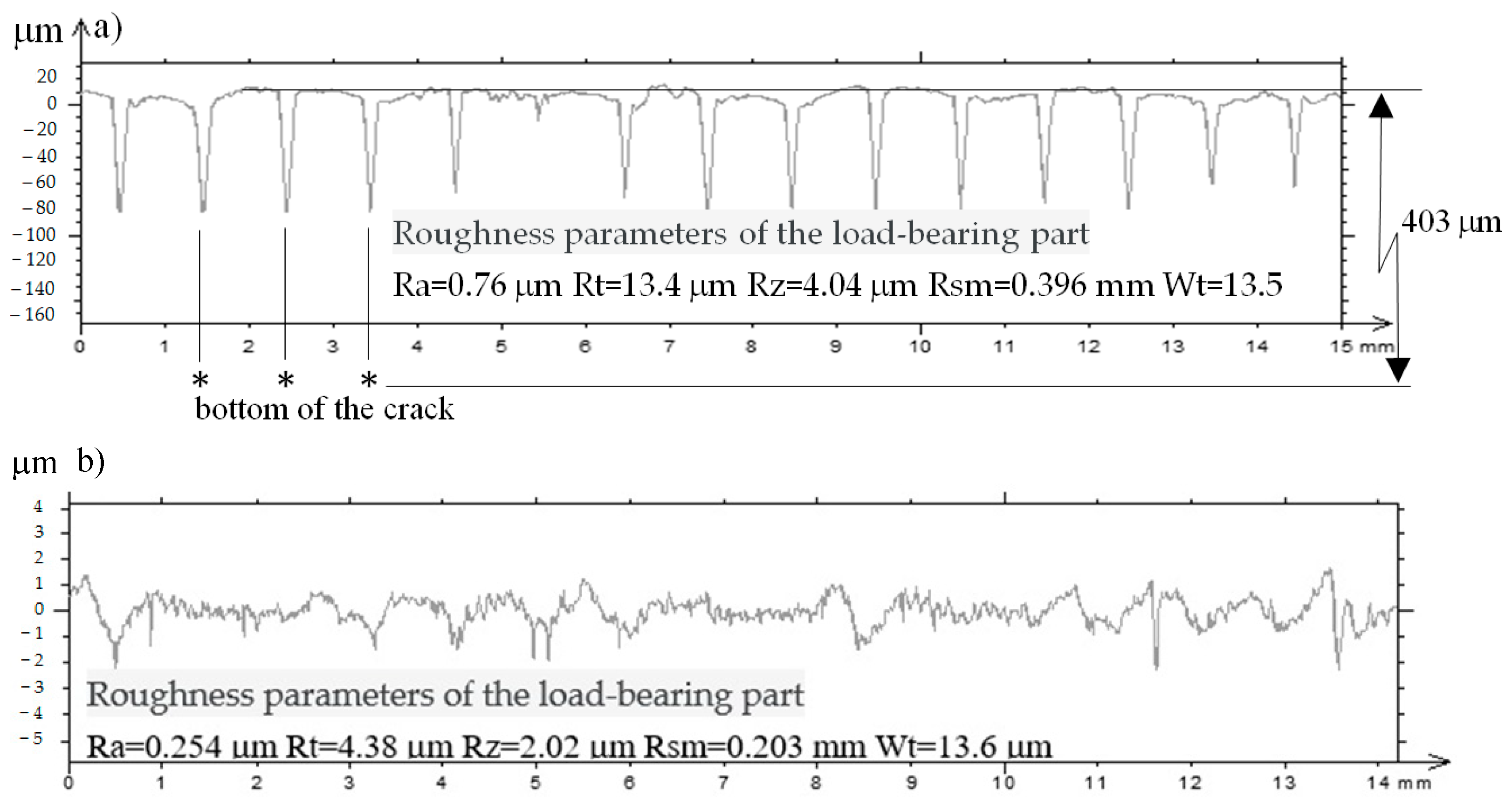
The material bearing of the burnished surface, depending on the top angle of the asperities after the previous treatment, was considered on the micro- and nanoscale. The results were obtained by performing surface measurements using a Hommel Tester T8000 profilometer and an NT 206 atomic force microscope (MTM, Minsk, Belarus).
The microstructure of the burnished surface was examined by analyzing microscopic photographs illustrating the changes that occurred on the surface of the processed material. For this purpose, a Tescan Mira scanning electron microscope was used (Tescan, Brno, Czech Republic).
The metallographic structure in the cross-section of the surface layer after burnishing, for various angles of the asperities obtained during the previous processing, were made on a Planar Micro 200 optical microscope with a magnification of 50, 100, 200 or 400.
3. Results and Discussion
3.2. Nano Surface Roughness after Rolling Burnishing
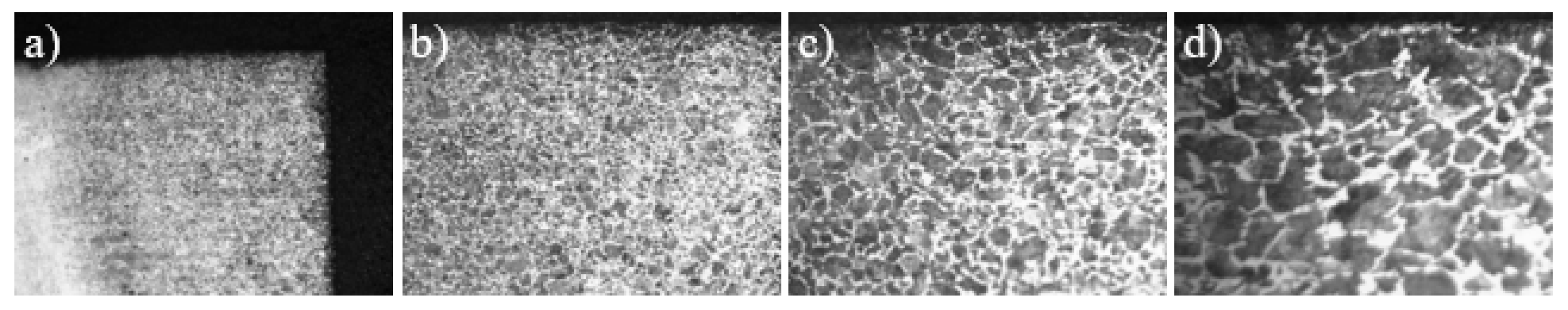
Atomic force microscopy can be used to analyze the roughness of the burnished surface in relation to a single asperity. It then becomes possible to move from the micro- to the nanoscale.
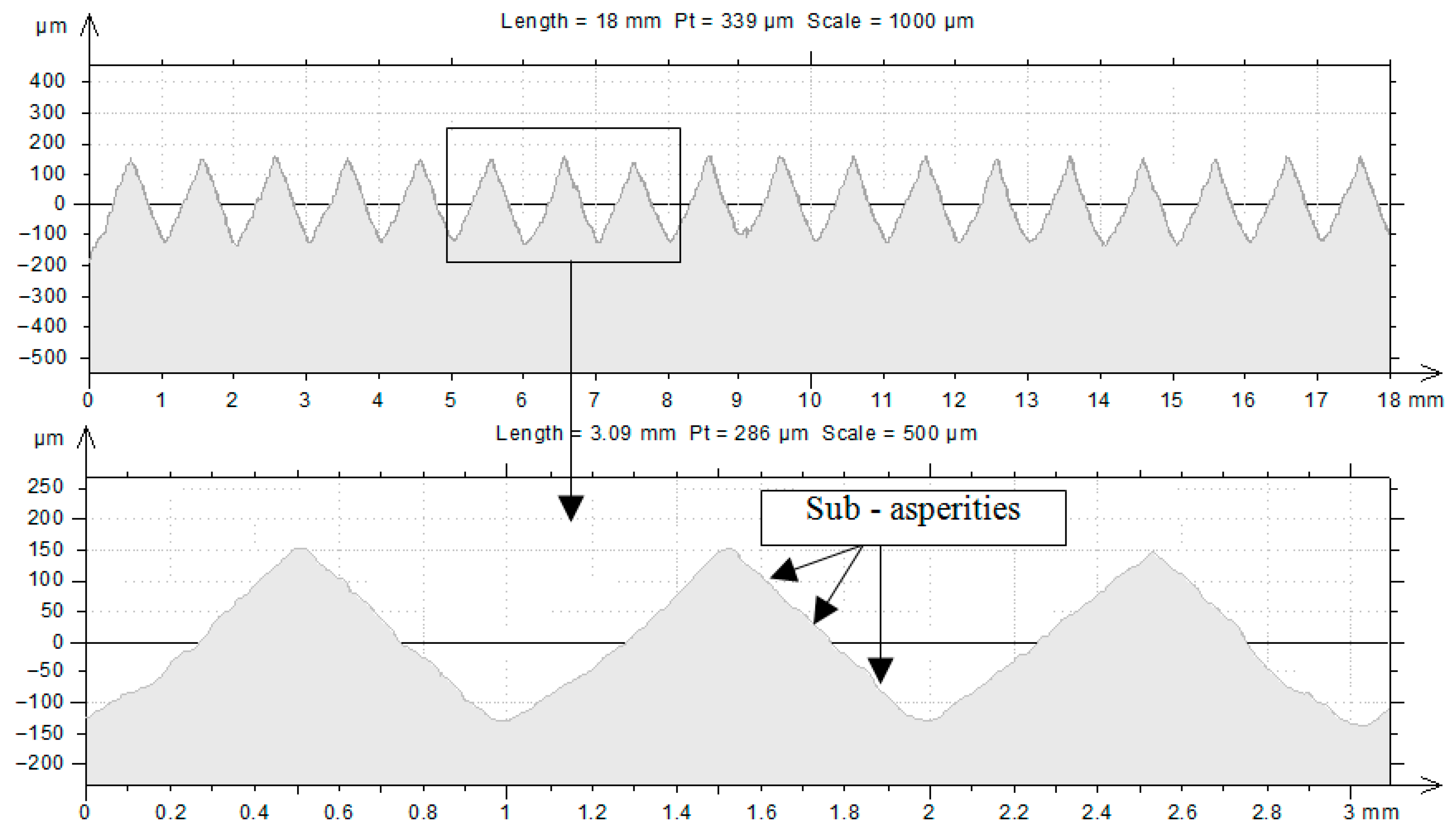
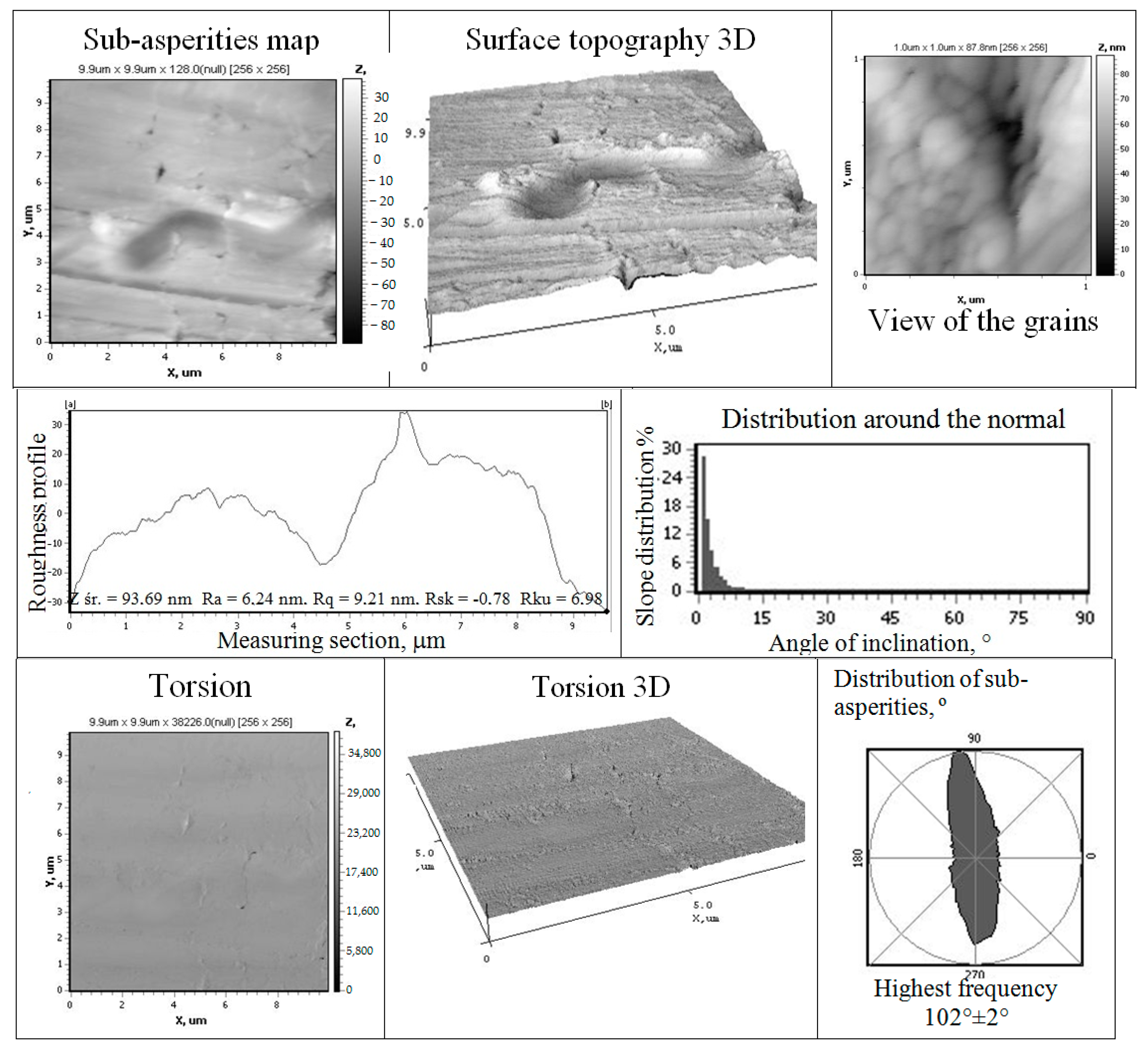
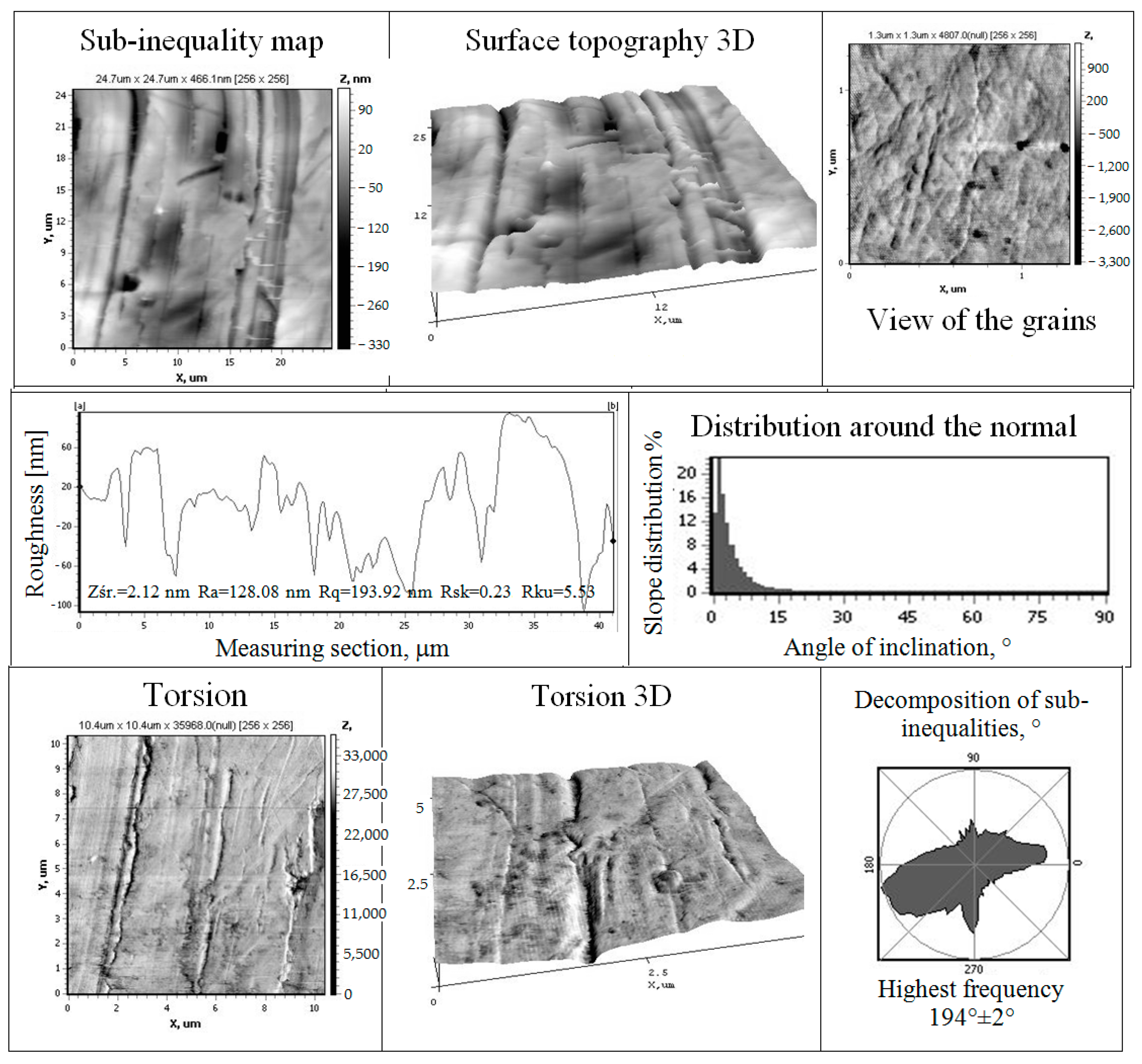
On the surface of each of the macro-scale asperities, there are sub-asperities (
Figure 5). The value of the height of sub-asperities and their arrangement may affect the tribological properties of parts after the burnishing process.
The results for the C45 steel shaft surfaces prepared by pre-turning with surface asperities with a vertex angle (
) are presented in
Figure 6 and
Figure 7. They include surface topography maps, a three-dimensional asperities diagram, a surface profile with roughness parameters in a selected cross-section, and some quantities defining the surface roughness properties, including roughness height distribution, orientation in relation to the surface normal, and distribution of the inclination angle to the normal in addition to grains of the processed material, as well as an image of the surface taking into account the rotation of the measuring probe by a very small angle as a result of torsional vibrations. The value of the height of sub-asperities and their arrangement may affect the tribological properties of the part. The results obtained are important when designing machine parts.
The result of the obtained roughness parameter is given in nanometers (nm), and the values on the OX and OY axes are expressed in micrometers (μm).
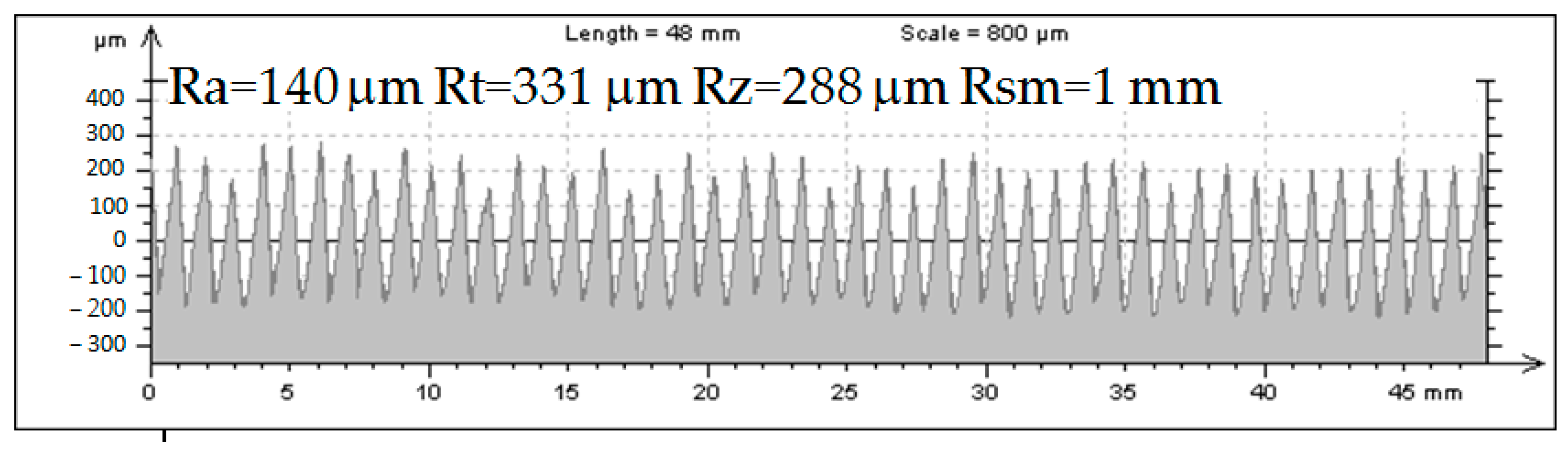
Figure 6 shows the results for a burnished surface whose vertical angle after machining prior to turning was
The presented sample measurement area was 9 × 9 µm and 1.0 × 1.0 µm in the case of observing grains of burnished material while maintaining a resolution of 256 × 256 measurement points. The analysis omitted the curvature of the cylindrical surface of the roller and projected it onto a plane. The results were also visualized in the form of a three-dimensional surface roughness graph, where micro- or even nano-surface cavities are visible. The determined values of roughness parameters for the tested surfaces are
, while the sum of the maximum value of positive roughness and the absolute value of negative roughness is
The results also include distribution functions of the roughness height for the roller surface area, as well as the distribution of the orientation of the asperities (hills and depressions) in relation to the normal (perpendicular to the mean line) to the tested surface of the same sample, and the distribution of the inclination angle of the asperities in relation to the normal to the sample surface and an image of the two-dimensional and three-dimensional surface taking into account the rotation of the measurement probe by a very small angle as a result of torsional vibrations.
For the surface with a vertex angle of 75°, the sample measurement area was 24.3 × 21 µm and 1.5 × 1.5 µm in the case of observing the grains of the pressed material while maintaining a resolution of 255 × 220 and 256 × 256 measurement points, respectively. The determined values of roughness parameters for the tested surfaces are while the sum of the maximum value of positive roughness and the absolute value of negative roughness is
Results for vertex angle 90°—the sample measurement area was 36.1 × 34.4 µm and 1.2 × 1.2 µm in the case of observing grains of the pressed material while maintaining a resolution of 226 × 215 measurement points. The determined values of roughness parameters for the tested surfaces are while the sum of the maximum value of positive roughness and the absolute value of negative roughness is
The results for the vertex angle 105° were visualized in the form of three-dimensional surface roughness graphs. The surface is characterized by greater uniformity than in previous cases. Very small pits are visible. The presented sample measurement area was 21 µm × 21 µm and 1.2 µm × 1.2 µm in the case of observing the grains of the pressed material while maintaining a resolution of 256 × 256 measurement points. The determined values of roughness parameters for the tested surfaces are while the sum of the maximum value of positive roughness and the absolute value of negative roughness is
For the surface with a vertex angle of 120°, the presented sample measurement area was 36.3 µm × 29.2 µm and 1.0 µm × 1.0 µm in the case of observing the grains of the pressed material while maintaining a resolution of 227 × 183 and 254 × 250 measurement points. The results were also visualized in the form of a three-dimensional surface roughness graph. The determined values of the roughness parameters are presented in the drawings. The differences between the parameters result from the size of the selected areas of the measurement surfaces. However, in all cases, they are rough on the nanoscale. The determined values of roughness parameters for the tested surfaces are: whereas
For the surface with a vertex angle of 135°, the presented sample measurement area was 20.4 × 20.4 µm and 1.0 × 1.0 µm in the case of observing the grains of the pressed material while maintaining a resolution of 256 × 256 measurement points. The results were also visualized in the form of a three-dimensional surface roughness graph, where micro- or even nano-surface cavities are visible. The determined values of roughness parameters for the tested surfaces are: while the sum of the maximum value of positive roughness and the absolute value of negative roughness is
For the surface with a vertex angle of 150°, the presented sample measurement area was 24.7 µm × 24.7 µm and 1.3 µm × 1.3 µm in the case of observing the grains of the pressed material while maintaining a resolution of 256 × 256 measurement points. The results were also visualized in the form of three-dimensional surface roughness diagrams as surface topographies and taking into account “torsion”. Nowadays, when technology strives to minimize (e.g., size) devices, apparatus and equipment, it becomes necessary to analyze surfaces at the nanoscale in order to ensure the appropriate quality of burnished components that can be used in them.
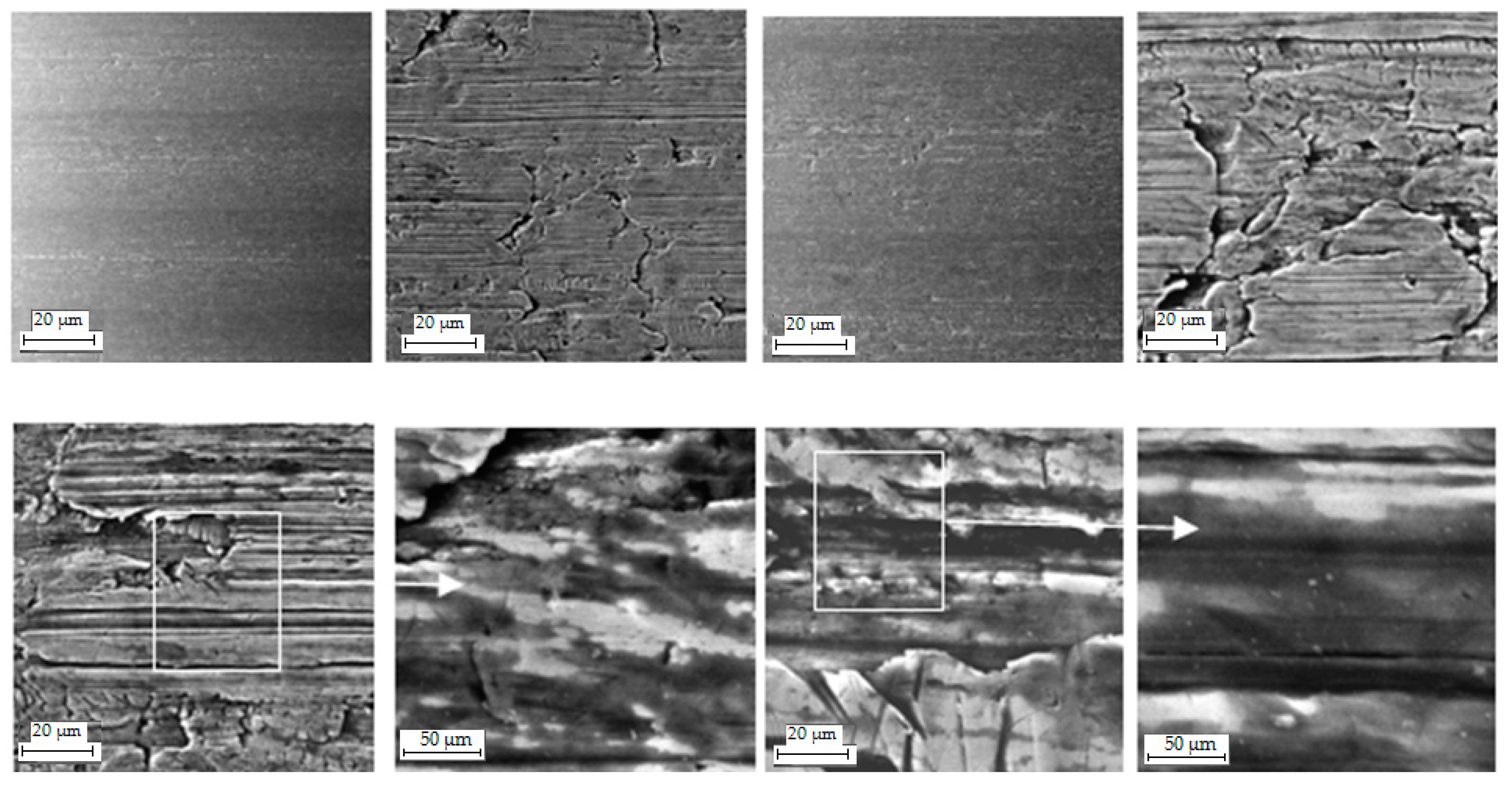
3.5. Metallographic Structure of the Surface Layer after Burnishing Depending on the Vertical Angle of the Asperities after Turning
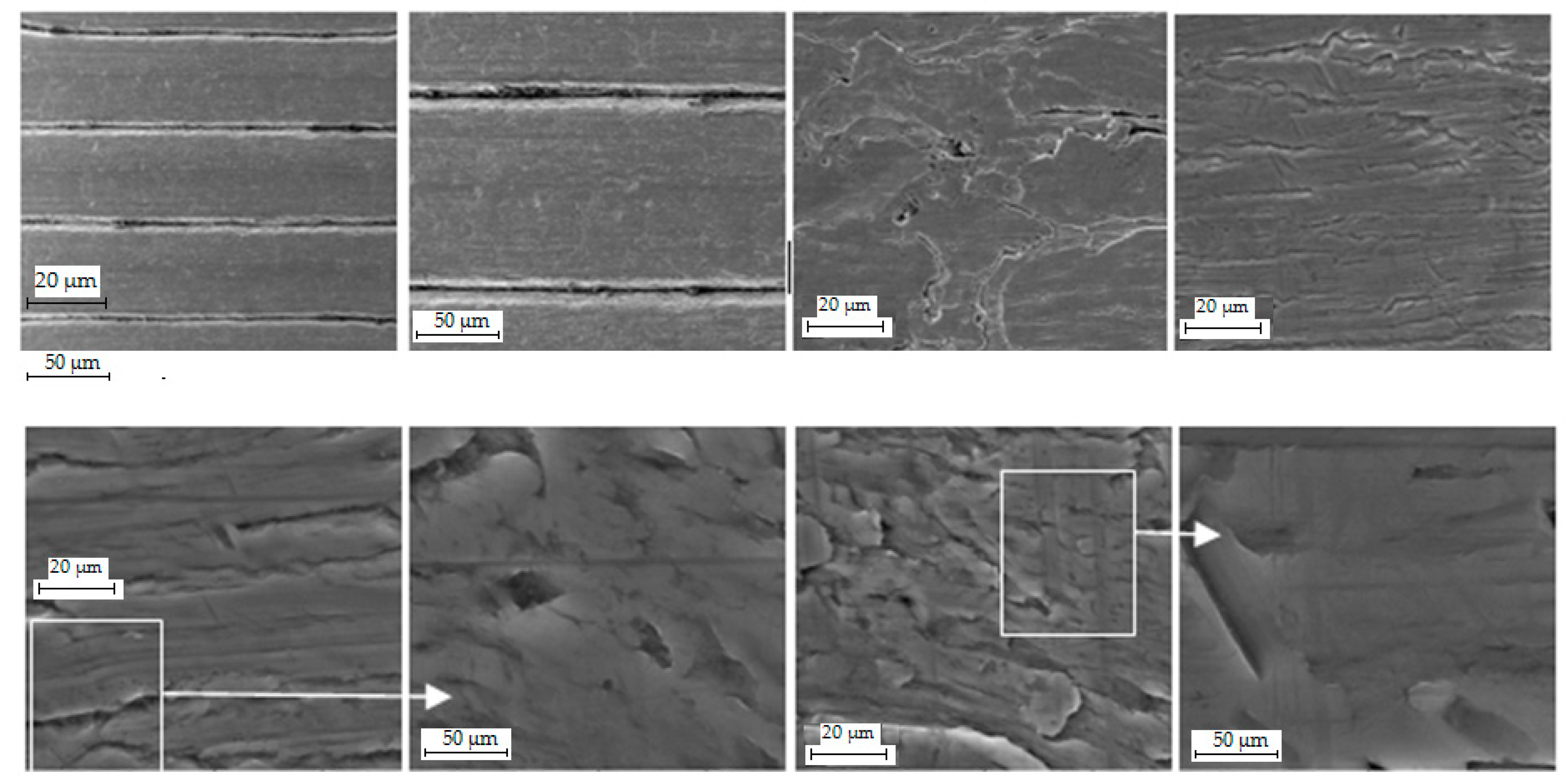
After burnishing, the surface layer is characterized by a zoned structure, which includes zones of fragmentation, plastic deformation, elastic deformation, and compressive residual stress. In some cases, some zones may not exist, have a changed size or penetrate each other. The metallographic structure of the surface layer formed by burnishing is influenced primarily by the method of burnishing, the values of the technological parameters of the process, the type of material and the type of preceding processing. The effects of burnishing in the surface layer include orientation and refinement of grains, texture, breakdown of retained austenite, precipitation of carbides and other phase transformations [
33]. The pressure force of the burnishing tool acting on the determined, regular, triangular asperities of the surface prepared by turning causes local elastic and plastic deformations in the contact zone with the workpiece. Since the hardness of the burnishing element is high, deformations occur mainly in the surface layer of the object. These deformations cause a change in the directional orientation and original shape of the grains. The grains are fragmented, flattened and elongated in the direction of the greatest deformations, creating a crushed texture. Plastic deformations occur to a certain depth from the surface of the object, depending on factors related to the burnishing process, mainly in the direction of slips occurring in the crystal lattice of the material. During the deformation occurring during burnishing, the crystallites are fragmented into fragments and blocks with high contamination of the crystal lattice. This continues up to a certain limit state, depending on the type of material being processed. The ability of the mesh to deform further is exhausted when the defect level reaches a limit value. Further deformation of the asperities results in the grinding of grains or displacement of crystals relative to each other, which contributes to the formation of material discontinuities in the form of microcracks [
33]. Examples of photos of the metallographic structure in the cross-section of the surface layer after burnishing for various angles of the asperities obtained during the previous processing are shown in
Figure 10 and
Figure 11.
After burnishing determined regular, triangular surface asperities, a specifically directed fibrous structure is created with the highest concentration in the near-surface zone. In the case of asperities with vertical angles , it can be noticed that the new texture created as a result of the impact of the burnishing tool covers the area of asperities. In these cases, the asperities were characterized by the greatest heights, the depth from the surface where fragmentation occurred, and the flattening of ferrite and pearlite grains covering the asperities. Pearlite and ferrite grains are flattened and arranged within the asperities along the arc. These grains are arranged convexly downwards. It is also visible in the case of these angles that there remains a gap between the asperities, and the bottoms do not rise. In the case of the remaining vertex angles of the turned inequality () and then burnished, a new texture was created, which also covers part of the core of the processed material. The greater the value of the vertical angle, the deeper this zone (including the core of the material) reaches. There are no clearly separated inequalities. However, it is possible to determine where the boundaries between asperities occur after image analysis because the grains are arranged, as in the previous cases, in a characteristic, directed way. The bottoms between the bumps have risen.
The structure of the surface layer of a burnished product depends on the structure of the material after the previous processing. For steel with a pearlitic–ferritic structure, a zone of strongly deformed and fragmented and oriented grains is observed, creating a texture with changed mechanical properties. The depth of plastic deformation and the direction of maximum grain elongation for a material with given plastic properties depend significantly on the parameters of the roughness profile after the preceding machining in the axial section and the outline of the active surface of the element burnishing and the apical angle of asperities obtained as a result of the preceding machining.
As a result of the impact of the burnishing disc on the surface of the steel prepared for burnishing with various angles of vertical asperities in the processing prior to turning, a strongly deformed and textured surface layer was created, different from the original material. The conducted research confirms the possibility of conscious influence on the condition and properties of the obtained surface layers by appropriate selection of the vertical angle of determined, regular, triangular asperities of turned surfaces.
4. Conclusions
The vertical angle of surface asperities after the turning process is another parameter influencing the geometric structure of the surface and the value of the roughness parameters of the burnished surface. This makes it possible to select turning and burnishing conditions in order to obtain a product with the required geometric structure due to the intended use of the product.
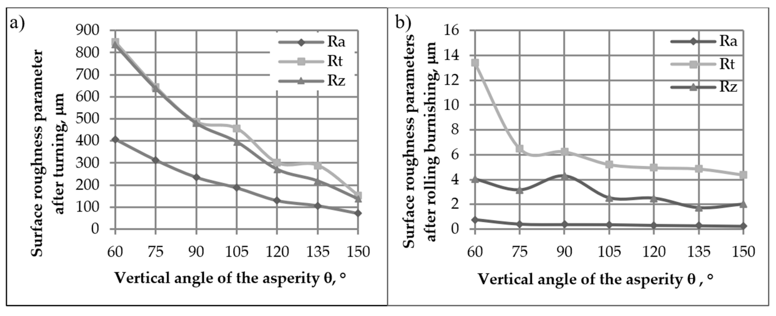
With the increase in the vertical angle of the surface asperities after turning, the surface roughness parameters decreased. Similarly, after the burnishing process, the larger the vertical angle of the asperities after turning, the lower the values of the roughness parameters after burnishing.
There are sub-inequalities on the surface of each macro-scale inequality. The value of the height of sub-asperities and their arrangement may affect the tribological properties of parts after the burnishing process.
Nowadays, when technology strives to minimize (e.g., size) devices and equipment, it becomes necessary to analyze surfaces at the nanoscale in order to ensure the appropriate quality of burnished components that can be used in them.
The material bearing of the burnished surface, depending on the vertical angle of the roughness after prior processing, was considered on the micro- and nanoscale.
As the top angle of the asperities changes, the nature of the material fraction curves changes. In the case when the asperities angle was after turning, a clearly progressive material curve was obtained after burnishing. The lower the surface asperities prepared in the preceding processing, the more proportional and progressive the material curves. In the case of the analyzed surfaces at the nanoscale, it is noticeable that the material curves are mixed—degressive and progressive—in each case. The obtained shapes of material curves are favorable from the point of view of load-carrying capacity, abrasion resistance and surface resistance to transferring contact loads.
Burnishing the surface with regular, determined, symmetrical asperities creates a new structure. Microscopic photographs taken with different magnifications show the structure of the material, revealing various-sized gaps remaining after processing, which is related to different values of the vertical angles of surface asperities after previous processing (turning). The greatest plastic deformations occur in the area of the tips of regular, determined, triangular surface asperities. Fragments of the roughness peaks were characterized by smoothness and uniformity of structure, which was also confirmed by the results of nanoroughness tests.
The conducted research allowed for the assessment of the influence of the vertical angle θ of asperities after turning on the surface quality after roll burnishing. It was found that increasing the value of the surface roughness angle in the turning process affects the surface quality after the burnishing process. It can be noticed that in the case of the vertical angle, where the surface roughness was the lowest, the structure is characterized by a large number of microcracks and crevices.
As a result of the impact of the burnishing disc on the surface of the steel prepared for burnishing with various angles of the apical asperities in the processing prior to turning, a strongly deformed and textured surface layer was created, different from the original material. The conducted research confirms the possibility of conscious influence on the condition and properties of the obtained surface layers by appropriate selection of the vertical angle of determined, regular, triangular asperities of turned surfaces.


