Article

Fundamental Atomistic Insights into Tunable Tribological Performance of NbC/Nb Films through Thickness and Depth Effects

Department of Mechanical Engineering, Northern Illinois University, DeKalb, IL 60115, USA
Metals 2024, 14(1), 2; https://doi.org/10.3390/met14010002
Submission received: 25 November 2023 / Revised: 13 December 2023 / Accepted: 18 December 2023 / Published: 19 December 2023
(This article belongs to the Special Issue Surface Engineering and Coating Tribology)

Abstract

:
Ceramic–metal nanolaminates (CMNLs) are promising scratch-resistant coatings, but knowledge gaps remain regarding the interactive effects of individual layer thickness and scratch depth. This study employed molecular dynamics simulations to investigate the tribological performance of NbC/Nb CMNLs, systematically varying ceramic and metal layer thicknesses (0.5–7.5 nm) and scratch depths (3, 5 nm). Models were loaded under displacement-controlled indentation followed by scratching. Mechanical outputs like material removal, friction coefficients, normal, and friction forces quantified scratch resistance. Material removal was even below that for NbC alone, demonstrating the multilayer benefit. Thinner layers showed complete penetration by the indenter, with material rolled in front rather than piled up. Thicker layers resisted penetration, enabling pile-up and lower friction coefficients due to higher normal forces. Excessive material removal decreased normal forces and raised friction coefficients. Peak coefficient occurred around 1.5–3 nm layer thicknesses where substantial top layer volumes were removed, minimizing ceramic under the indenter. Layer thickness corresponding to lowest material removal depended on scratch depth, with 3 nm and 7.5 nm layer thickness for 3 and 5 nm depths, respectively. Metallic layers reduced stiffness and drove material downward over piling up. Quantifying scratch resistance versus geometric parameters elucidates fundamental physics to facilitate superior CMNL coating fabrication.

1. Introduction

Ceramic/metal nano-laminates (CMNLs) consist of alternating layers of ceramics and metals, with layer thicknesses on the order of nanometers. The diminished layer thickness in CMNLs provides additional mechanical benefits, with precise control over the nanoscale structure of the laminates. Moreover, the interface effect between ceramic and metal layers assumes a more pronounced role in CMNLs compared to conventional CMLs, further enhancing their mechanical properties [1,2,3,4,5].
Ceramic–metallic nanolaminates (CMNLs) have shown promise as wear (scratch) resistant coatings for extreme tribological conditions [6,7,8,9,10,11,12]. To name a few, metal (Cr, Zr)/ceramic (CrN, ZrN) multilayers were coated on Si wafers and AISI 316L steel [6], and TiN/Ti multilayers were used as coating on soft austenitic steel [7], Si (100) [11], and AZ31 magnesium alloy [12] substrates. Wear is a failure mechanism that can severely impact the performance and reliability of mechanical systems across industrial, economic, and environmental domains. The rapid advancement of nano/microelectromechanical systems (NEMS/MEMS) technology has brought increased attention to overcoming wear issues in devices with critical dimensions in the nano/micrometer ranges [13]. Studies have demonstrated that CMNLs can have higher critical loads compared to their individual layer counterparts. Critical load refers to the load required to penetrate through the CMNL coating to the substrate below [9]. The interfaces between the ceramic and metallic layers in CMNLs also help reduce friction and wear. Ti2AlN/TiAl multilayers exhibited lower friction coefficients and wear, attributed to the interface effects on plastic deformation of the individual layers [14]. The high hardness and stiffness of the ceramic layers coupled with easier slip in the soft metallic layers further improve the scratch resistance of CMNLs [7,9,12,15,16].
The tribological performance of ceramic–metallic nanolaminates (CMNLs) in particular and other nanolaminates in general can be tuned by several key parameters including individual layer thickness, interface structure, scratch direction, scratch velocity, surface orientation, indenter geometry, indentation depth, and temperature. Studies have revealed that the scratch direction and surface crystallographic orientation influence the shape and volume of material removed during scratching, relating to the activation of different slip systems [14,17,18].
Han et al. [14] found that Ti2Al/TiAl nanolaminates with incoherent interfaces exhibited lower friction coefficients during scratching. According to their analyses, the atomic mismatch at incoherent ceramic/metal interfaces facilitates dislocation transmission from one layer into the next. This promotes slip and plastic flow, reducing the tangential forces and resulting friction coefficients.
Studies by Zhang et al. [19], Han et al. [14], and Tian et al. [20] demonstrated that scratching speed significantly impacts the tribological performance of nanolaminates. At higher speeds, dislocations have less time to move away from the stressed region in front of the indenter before the next loading cycle. This leads to increased dislocation densities, pile-ups, and resultant friction coefficients.
Indenter shape is another important factor, as demonstrated by Gao et al.’s molecular dynamics study comparing blunt and sharp indenters on a Ni alloy film [18]. The sharper indenter produced higher friction coefficients due to more concentrated stresses. Alabd Alhafez et al. [21] also showed that conical indenter angle impacts nano-scratching in Fe, with larger angles decreasing friction but increasing hardness.
Several studies have probed the influence of scratch depth on tribological response. Investigations on Fe [22] and Ni/Al [23] nanolaminates revealed increased friction at higher penetration depths, attributed to greater energy required to displace more material and larger contact areas that increase normal and tangential forces. Transverse and normal hardness also grew with depth as more material piled up around the indenter [22].
On the effect of layer thickness on the tribological behavior of nanolaminates, Nasim et al. [24] explored the tribological behavior of Ta/Co nanolaminates with the individual layer thickness ranging between 5 nm and 100 nm. They reported highest scratch and wear resistance with minimal plastic deformation for the nanolaminates with 5 nm layer thickness. They linked this behavior to the strong cohesive strength of the individual layers for these samples. Zhou et al. [25] showed a significant effect of both individual layer thickness and modulation ratio on the flow strength and scratch resistance of Ti/Cu nanolaminates. Wear rate and friction coefficients showed slight opposing trends, as samples with thicker Ti layers compared to Cu layers showed lower wear rate but higher friction coefficients. These behavior was linked to the higher hardness of the samples with thicker Ti layer as Ti is harder than Cu. Hua et al. [26] noticed significant size effect for the tribological properties of Cu80Zr20/Cu20Zr80 nanolaminates where the friction force significantly changed with the layer thickness.
Recently, Uddin and Salehinia [15] analyzed the nanoscratching behavior of NbC/Nb CMNLs using different indenter sizes but a fixed 2 nm ceramic thickness. The CMNLs showed lower material removal than NbC and Nb alone, demonstrating their improved scratch resistance. Metal layer thickness strongly affected mechanical response, with thinner metallic layers showing higher friction and scratch forces, particularly for smaller indenters. The study also revealed unique deformation patterns in the ceramic layers. However, the interactive effects of layer thickness and penetration depth remain unexplored.
While the reported studies have advanced our understanding of tribological properties in ceramic–metallic nanolaminates (CMNLs), there remain important knowledge gaps, particularly regarding the interactive effects of individual layer thickness and scratch depth. Uddin and Salehinia’s recent work provided valuable insights into the influence of metallic layer thickness in NbC/Nb nanolaminates on material removal, friction coefficients, and deformation patterns under nanoscratching [15]. However, their study only varied the Nb layer thickness while keeping the NbC ceramic thickness fixed at 2 nm. The scratch depth was also not systematically explored across models with different metal thicknesses. To fully elucidate the scratch resistance mechanisms and deformation behavior of CMNLs, it is critical to probe how nanolaminates with different ceramic and metallic layer thicknesses respond tribologically to scratches of varying depth.
We employed molecular dynamics (MD) atomistic simulations to explore the scratching behavior of NbC/Nb multilayer samples, varying the thickness of individual layers. Additionally, we changed the penetration depth to examine its influence on the tribological characteristics of these multilayer nanolaminates. Material removal, friction coefficient, normal and scratching force, and the dominant deformation mechanisms were investigated. MD enables direct examination of dislocation activities and interactions within the material’s nanostructure under mechanical loading that would be difficult or impossible to visualize experimentally or using other computational methods. On the other hand, in MD simulations, one can explore the effect of a single geometrical, physical, or mechanical property on the mechanical behavior, an action that is almost impossible in experiments due to a mixture of various parameters that can impact the material behavior at the same time.

2. Simulation Details

Molecular dynamics simulations were performed using the LAMMPS code [27] along with 2NN-MEAM interatomic potentials [28] for the NbC/Nb system. This ceramic/metal pair was chosen based on the authors’ prior extensive research [2,15,29], comprising a combination of hard, stiff NbC layers with soft, compliant Nb layers.
The interface configuration between NbC and Nb followed the Baker–Nutting orientation relationship. Specifically, the (001) planes of the Nb and NbC single crystal layers formed the interface. The [100] NbC crystal direction (aligned with the x-axis in Figure 1) was parallel to the [110] Nb direction [29].
Periodic boundary conditions were applied to the lateral faces of each model. The top surface remained free, while the bottom surface was fixed to prevent rigid motion during indentation. The minimum width of each CMNL was selected to minimize coherency strains, ensuring minimal boundary effects on the results [29].
This study investigates the effects of two key parameters on the tribological performance of NbC/Nb nanolaminates: individual layer thickness and penetration depth. Regarding layer thickness, models with varying individual thicknesses for both NbC and Nb were constructed, while maintaining a 1:1 ceramic/metal thickness ratio. The total multilayer thickness was fixed at 30 nm; therefore, models with thinner individual layers contained more discrete layers. Single crystal Nb and NbC were also simulated for comparison. For penetration depth, values of 3 nm (PD3) and 5 nm (PD5) were tested at a constant 5 nm indenter radius. The in-plane dimensions of the nanolaminate models were 40 nm, which minimizes boundary condition effects on scratching behavior, as larger dimensions showed negligible changes beyond increased computational cost. Further geometric details and atom counts for each model are listed in Table 1. Models are named based on individual layer thickness; for example, LT0.5 has 0.5 nm thick NbC and Nb layers.
A rigid spherical nanoindenter was employed for displacement-controlled indentation normal to the surface (−y) followed by scratching parallel to the surface (+x) (see Figure 1). Indentation and scratching speeds were 100 m/s and 250 m/s, respectively [30]. The lower indentation speed avoids disturbances from the abrupt indenter-sample contact while yielding no noticeable difference in deformation behavior versus faster scratching. A 20 nm total scratch length enabled stabilization of mechanical outputs like material forces, friction coefficients, and removal volumes.
The models underwent an energy minimization using the conjugate gradient method followed by a 10 ps NPT (isothermal-isobaric) dynamic relaxation at 10 K and zero pressure. These preliminary simulations served to equilibrate the models prior to indentation and scratching. A microcanonical ensemble was applied during the nanoindentation and nanoscratching deformation simulations, which also maintained a temperature of 10 K. This low temperature aided visualization of deformation mechanisms. Across all simulations, the time step was 1 fs.
The friction coefficient (μ) can be defined as the ratio between the scratching (Fs) and the normal loads (Fn) encountered during the scratching process, as expressed by Equation (1):
F s = μ F n
To calculate the normal and scratching loads, a quadratic repulsive force model for the rigid indenter was used in LAMMPS, as described in Equation (2) [27]:
F = K R r 2
Here, K represents the force constant, set at 1 eV/Å [15], r signifies the distance from an atom to the center of the indenter, and R represents the radius of the indenter.

3. Results and Discussion

This section reports the mechanical behavior of multilayer nanolaminates under indentation and scratching loading. In particular, friction coefficient, friction and normal forces, and material removal for various cases will be studied and discussed.
Figure 2 illustrates the load–depth curve during nanoindentation for the nanolaminates listed in Table 1, NbC, and Nb single crystals when indentation was 5 nm deep. As anticipated, the NbC single crystal exhibits the highest load at any given depth, while the Nb single crystal displays the lowest load. Additionally, it is observed that as the ceramic layer thickness increases, the indentation load at the same depth also rises. An intriguing finding is the discernible change in the load–depth curve for nanolaminates with individual layer thickness greater than 2 nm. This change indicates the transition from elastic behavior to plasticity in the NbC layer. Notably, as the NbC layer thickens, this transition becomes more pronounced, manifesting as clear peaks in the load–depth curve for NbC single crystals and nanolaminates with layer thicknesses of 7.5 nm and 5 nm. These clear peaks signify the abrupt onset of plasticity or failure in the top NbC layer, while the underlying Nb layer remains in the elastic regime, not contributing significantly to the overall mechanical behavior of the nanolaminates. The onsets of plasticity shift to the right as the thickness of the NbC layer is reduced, due to more compliance that the metallic layers add to the nanolaminates. Conversely, as individual layers become thinner, metallic layers play a more substantial role in the overall mechanical behavior, resulting in a more gradual change in the load–depth curve. In nanolaminates with thin individual layers, particularly in the thinner part of the spectrum, the metallic layer exhibits plasticity even before any signs of plasticity or failure activities are evident in the ceramic layers. Figure 3a,b show the atomic snapshot of the top most metallic layer (also named as Nb1 layer) at the depth where the slope of the load–depth curve changes for LT3 and LT7.5 nanolaminates, respectively, i.e., depth of 15.3 Å for LT3 model and depth of 13.9 Å for LT7.5 model, and also at 3 nm indentation depth. The dislocations network is very well developed and reaching to the opposing interface for LT3, indicating the large plastic deformation in the metallic layer for both indentation depth, but for LT7.5 dislocations are much fewer even at the end of the indentation process. For nanolaminates, the rate of increase in load with depth significantly drop indicating more significant contribution of the metallic layers compared to lower penetration depths.
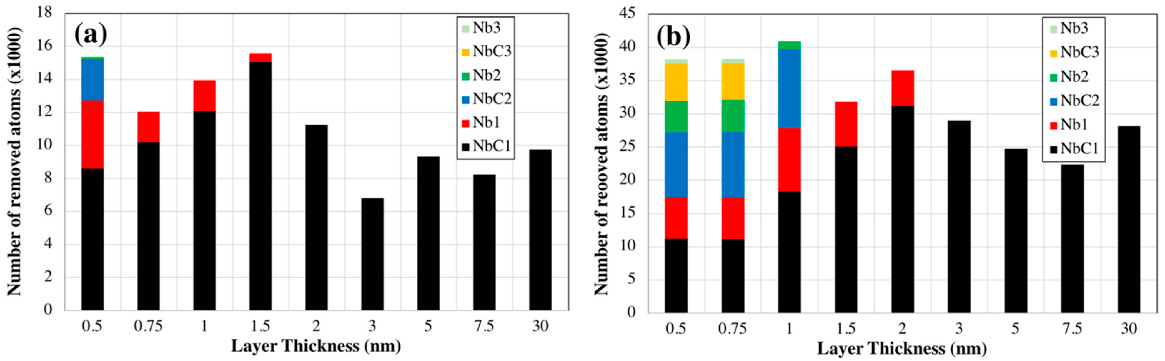
Material removal is another parameter that is used to compare the mechanical behavior of materials under scratching load. In mechanical applications, materials with lower wear rate are preferable, as a higher wear rate results in dimensional inaccuracy and increased friction. 
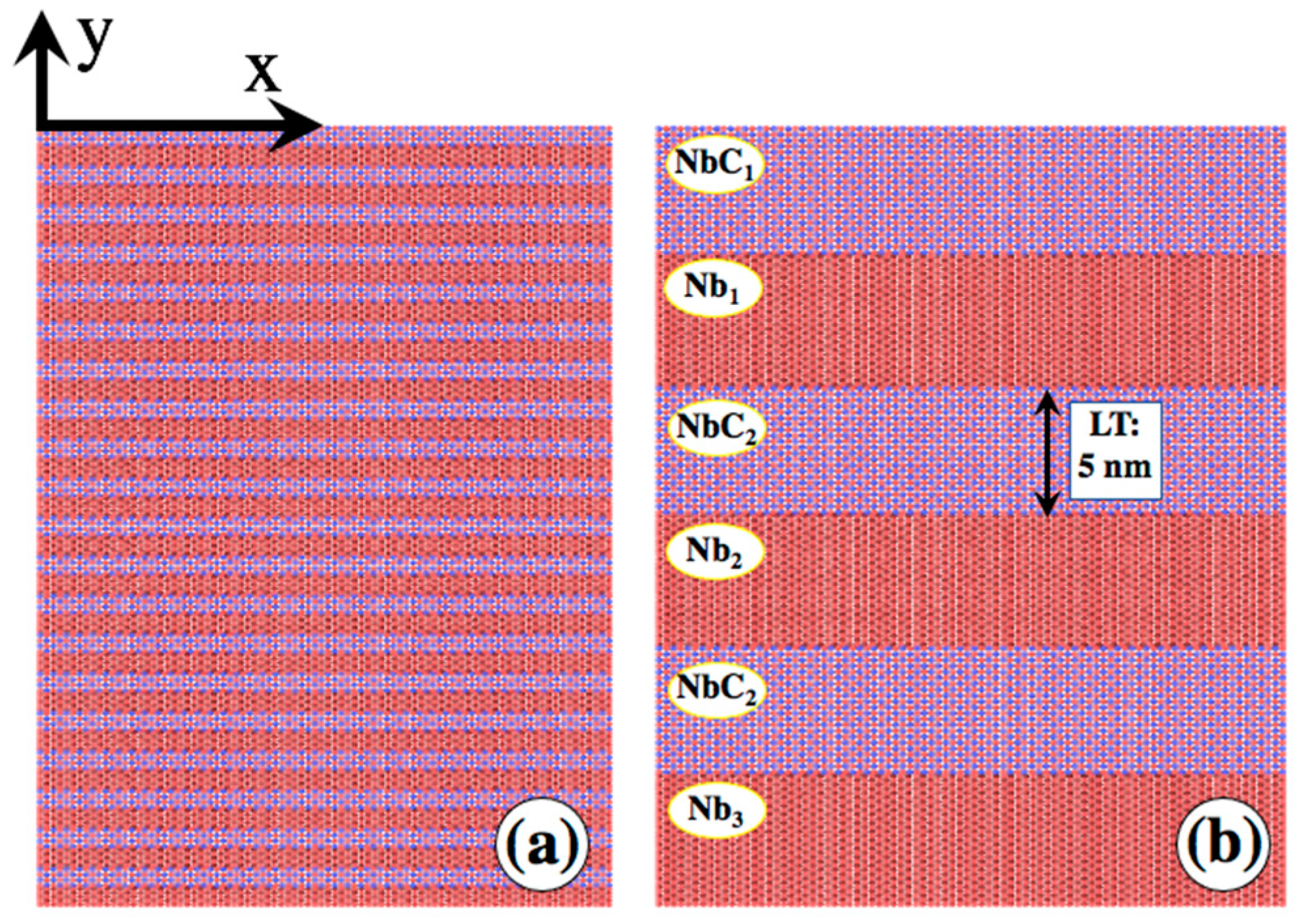
Figure 4a,b show the variation in material removal for various models at penetration depths of 3 nm and 5 nm, respectively. At the end of the indentation, atoms might pile up around the indenter, however this is not due to scratching. To endure that only material pile-up caused by scratching was measured, for any layer, atoms were counted as removed if their y coordinates exceeded the maximum y coordinate of the layer at the end of indentation process. The y-axis shows the total number of removed atoms at 20 nm of scratching distance. For clearer visualization, the number of removed atoms was divided by 1000. For each model, the total removed atoms were separated into those removed from individual layers, numbered from the topmost ceramic layer (NbC1, Nb1, NbC2, etc.). This shows the extent of indenter penetration into the layers. For example, at 3 nm penetration depth, the LT0.5 model indicates the indenter penetrated the second NbC layer (i.e., NbC2). In fact, LT0.5 is the only model where material from the second ceramic layer was removed. Removal of atoms from the top metallic layer even occurred for LT1.5. When the indenter pierces a layer, material removal is no longer gradual—the whole layer is rolled in front of the indenter. High material removal for models with individual layer thickness under 1.5 nm indicates this behavior. The same is seen at 5 nm penetration depth, where all models with layer thickness under 2 nm were pierced through the top ceramic layer. For LT0.5 and LT0.75, the indenter penetrated the top five layers. The lowest material removal at 3 nm and 5 nm penetration depths occurred for LT3 and LT7.5 models. Interestingly, removal for these models is less than that for a single NbC layer, indicating the benefit of the multilayer structure. At 3 nm penetration, LT3, LT5, and LT7.5 show lower removal than the NbC single layer. At 5 nm, LT5 and LT7.5 show lower removal than the single NbC layer. As mentioned by Uddin and Salehinia, the metallic layers reduce stiffness, resulting in a tendency to push material down rather than piling it up. As the top ceramic layer thickness increases, behavior approaches that of a single NbC crystal since metallic layers contribute less to the overall mechanics.
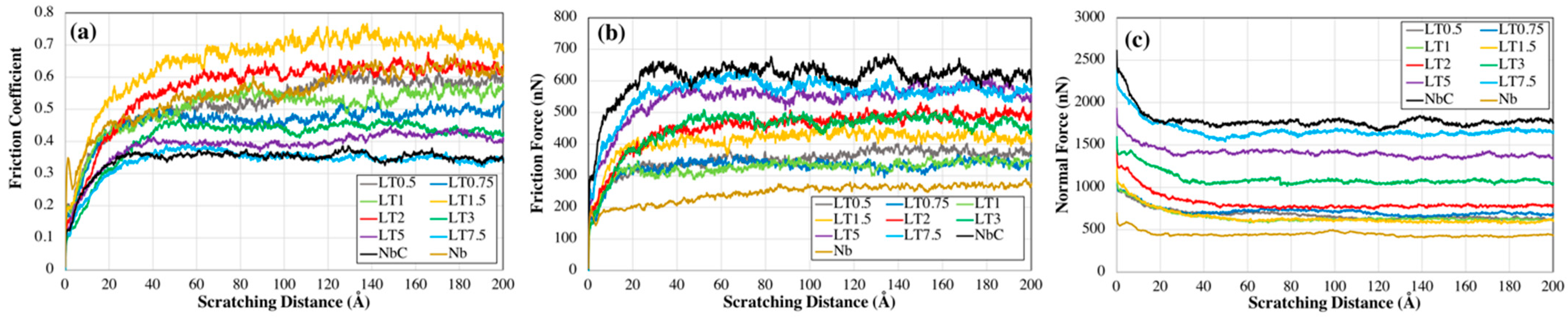
Figure 5a–c show the variation in friction coefficient, scratching (friction) force, and normal force with scratching distance for the models in Table 1 at a penetration depth of 3 nm. 
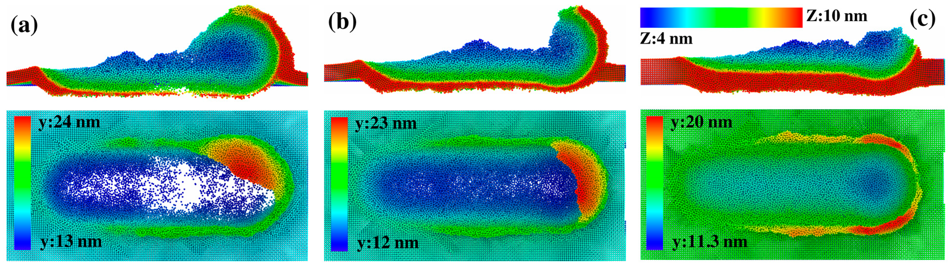
Figure 6a–c show atomic snapshots of the LT1.5, LT2, and LT3 models at 20 nm scratching distance, including sectioned side views and top views. The friction force and normal force represent the total loads applied to the indenter in the scratching (x) and normal (y) directions, respectively. The friction coefficient and friction force show increasing trends until saturation, while the normal force decreases. The observed trend are in good agreement with those reported elsewhere [14,18,22,23,26]. The sudden drop in the normal load occurs as atoms behind the indenter lose contact, reducing the total load in the y direction. The curves demonstrate the models’ scratching behavior depends on individual layer thickness, although models on the lower end of the thickness range show less sensitivity. Friction force sensitivity is particularly low for these models. Normal force is also similar, but even slight changes significantly impact the friction coefficient in Figure 5a.
The NbC model shows the lowest friction coefficient due to an extremely high normal force. In contrast, the LT1.5 model has the highest friction coefficient despite a moderate friction force, because of an extremely low normal force compared to other nanolaminates. Figure 6a shows that the top NbC layer in the LT1.5 model is thinned and even pierced extensively, leaving minimal material under the indenter at 20 nm and resulting in the very low normal force.
The lowest friction force occurs for the Nb single crystal, indicating easier scratching. The nanolaminates exhibit higher forces, demonstrating improved tribological behavior over the single metal.
As shown in Figure 4a, at 20 nm scratch distance, models LT0.5, LT0.75, and LT1 displayed complete penetration of the indenter through the top ceramic layer. Consequently, this layer contributes less to mechanical behavior compared to the models with thicker layers. Of these three models, LT0.5 exhibits the highest friction force since the indenter is directly in touch with the second NbC layer. In contrast, for thicker-layered models like LT2, LT3, LT5, and LT7.5, scratching only creates pile-ups in the top layer, inducing higher friction forces versus thinner layered nanolaminates (see Figure 6c). With the indenter remaining inside the top ceramic layer, normal forces are also higher for thick-layered models, lowering their friction coefficients.
Interestingly, despite comparable friction forces for LT2 and LT3 models, the higher normal force of LT3 leads to a significant drop in friction coefficient from 0.6 to 0.43. For both, the indenter stays in the top NbC layer. However, LT2 shows much greater material removal, dramatically reducing its normal force relative to LT3. The extreme thinning of the top ceramic layer due to excessive material removal for LT2 model is apparent in Figure 6b. Of models LT2, LT3, and LT5, LT5 demonstrates the highest friction and normal forces. Yet among the three, LT3 maintains the lowest material removal. Strongly influenced by the normal force, the friction coefficient for LT5 was the lowest.
These observations demonstrate material removal significantly impacts normal force. When the indenter remains in the top ceramic layer, normal force shows the most impact on the friction coefficient. The reduced removal for LT3 vs. LT5 and LT7.5 results from greater metallic layer contribution to nanolaminate stiffness, as it results in less resistant for pushing the material down, leading to less material removal.
Figure 7a–c show the variation of friction coefficient, scratching (friction) force, and normal force with the scratching distance for various models listed in Table 1, when penetration was 5 nm. Almost similar trends are seen for the two penetration depths; however, a deeper analysis of the curves results in better understanding of the combined effects of individual layer thickness and the penetration depth on the tribological behavior of the nanolaminates.
For similar models, friction coefficient increases with greater penetration depth as friction force changes more significantly between the two depths compared with the normal force. Figure 8 shows the variation of friction force and normal force with the layer thickness for the two penetration depths. The values of the forces on the y axis were calculated by averaging the forces between 10 and 20 nm scratching distance when mechanical behavior shows stability.
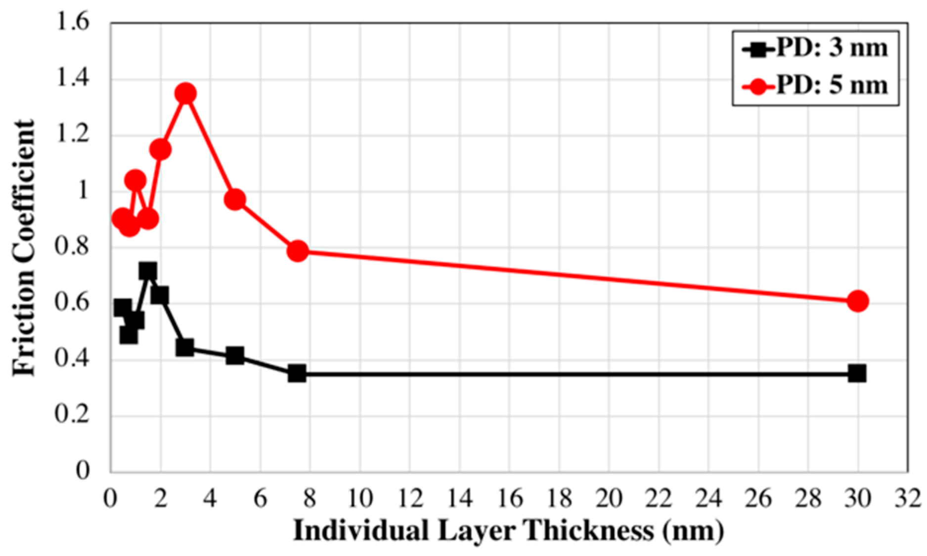
Figure 9 shows friction coefficient variation with individual layer thickness for penetration depths of 3 nm and 5 nm. The values were obtained by averaging friction coefficients from 10 to 20 nm scratch distance. Both curves display the same trend, i.e., friction coefficient rises to a peak with increasing layer thickness, then drops as thickness further increases. The layer thickness corresponding to peak friction coefficient differs for the two depths, occurring at 1.5 nm and 3 nm for the penetration depths of 3 nm and 5 nm, respectively.
Model LT3 exhibits highest friction coefficient, but only intermediate friction forces. The combination of moderate friction forces and extremely low normal forces yields highest friction coefficients for this model. Normal forces are low because substantial volumes of the top NbC layer are removed during scratching, leaving minimal ceramic directly under the indenter. In other words, the indenter nearly reaches the metal layer below, no longer experiencing the high NbC hardness. 
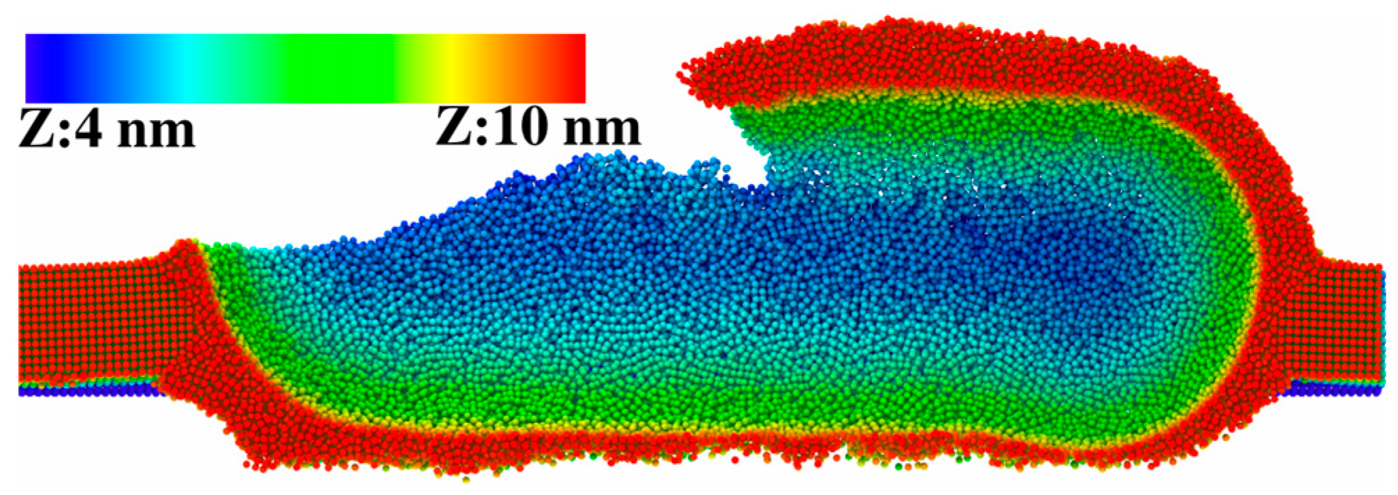
Figure 10 shows the sliced atomic snapshot for model LT3 after 20 nm scratching at 5 nm depth. Removal of the top ceramic layer material under the indenter is apparent. Comparable (or even lower) normal forces are seen for the models with thinner individual layer thicknesses; however, their friction forces are much lower than those for LT3, resulting in lower friction coefficients. Much lower friction forces for these nanolaminates are due to a complete piercing of the top NbC layer.
Overall, the results presented in this manuscript have highlighted the critical role of layer thickness in optimizing the tribological performance of multilayer coatings. The fundamental insights into the design of NbC/Nb nanolaminates expand the potential applications for robust nanolaminate coatings under extreme contact stresses. The quantitative structure–property relationships provide guidelines that will facilitate experimental efforts to fabricate and validate high-performance NbC/Nb films specifically, and ceramic/metal nanolaminates broadly. Moreover, the modeling methodology establishes a framework for elucidating non-intuitive connections between structure and performance, thus expediting materials innovation through predictive, physics-based design.

4. Conclusions

Molecular dynamics atomistic simulations were performed in LAMMPS to study the impact of individual layer thickness and the penetration depth on the scratching behavior of NbC/Nb nanolaminates. Layer thicknesses in the range of 0.5 nm to 7.5 nm and penetration depths of 3 and 5 nm were considered. Material removal, friction coefficient, friction (scratching) force, and normal force were utilized to understand the behavior of nanolaminates under the mechanical loading.
Simulations show significant effects of both parameters on the tribological behavior of the nanolaminates. For each penetration depth, there existed nanolamitaes that show less material removal compared to NbC. NbC/Nb nanolaminate models with the lowest material removal were different for different penetration depths, i.e., models with individual layer thickness of 3 nm for penetration depth of 3 nm and the model with 7.5 nm layer thickness for the penetration depth of 5 nm.
The friction coefficient did not exactly follow the same trend as the material removal, as the highest friction coefficient for the penetration depth of 3 nm was for the model with the layer thickness of 1.5 nm and that for the penetration depth of 5 nm was for the model with 3 nm layer thickness. The interplay between the removed material, normal force, and friction forced resulted in this difference. When the material removal on the top NbC layer was excessive and the remained NbC under the indeter was thin, the normal force was lower, resulting in the higher friction coefficient.
The conducted molecular dynamics simulations offer valuable insights into the fundamental physics governing the material’s mechanical response under the applied scratching load. One advantage of utilizing atomistic simulations over experimental approaches in materials design lies in their ability to isolate and assess the impact of specific geometric parameters on the mechanical response of materials, holding other factors constant. This enables a more detailed understanding of how individual variables contribute to the overall tribological behavior of the system.
It is crucial to recognize that trends observed in atomistic simulations may not align with the behavior at micro and macro scales due to size effects as the length scale increases and the interplay between various parameters that impact the materials’ behavior. Larger-scale phenomena, such as crack propagation and dislocation dynamics, are beyond the scope of small-scale MD simulations. However, this does not minimize the significance of insights gained from atomistic simulations. Rather, in the future work, atomistic simulations can be used to inform multiscale models in order to develop a thorough understanding of materials’ behavior across length scales. These larger-scale simulations capture the interplay between atomistic processes and microstructural features, providing a holistic view of the mechanical response.

Funding

This research received no external funding.

Data Availability Statement

The data presented in this study are available on request from the corresponding author. The data are not publicly available due to limited cloud storage.

Acknowledgments

The author would like to thank the Center for Research Computing & Data at Northern Illinois University for their support and providing access to their computer cluster, GAEA.

Conflicts of Interest

The author declares no conflict of interest.

References

  1. Bhattacharyya, D.; Mara, N.A.; Dickerson, P.; Hoagland, R.G.; Misra, A. Compressive Flow Behavior of Al-TiN Multilayers at Nanometer Scale Layer Thickness. Acta Mater. 2011, 59, 3804–3816. [Google Scholar] [CrossRef]
  2. Salehinia, I.; Shao, S.; Wang, J.; Zbib, H.M. Interface Structure and the Inception of Plasticity in Nb/NbC Nanolayered Composites. Acta Mater. 2015, 86, 331–340. [Google Scholar] [CrossRef]
  3. Li, N.; Wang, H.; Misra, A.; Wang, J. In Situ Nanoindentation Study of Plastic Co-Deformation in Al-TiN Nanocomposites. Sci. Rep. 2014, 4, 6633. [Google Scholar] [CrossRef] [PubMed]
  4. Deng, X.; Chawla, N.; Chawla, K.K.; Koopman, M.; Chu, J.P. Mechanical Behavior of Multilayered Nanoscale Metal-Ceramic Composites. Adv. Eng. Mater. 2005, 7, 1099–1108. [Google Scholar] [CrossRef]
  5. He, J.L.; Li, W.Z.; Li, H.D.; Liu, C.H. Plastic Properties of Nano-Scale Ceramic–Metal Multilayers. Surf. Coat. Technol. 1998, 103–104, 276–280. [Google Scholar] [CrossRef]
  6. Guan, X.; Wang, Y.; Xue, Q. Effects of Constituent Layers and Interfaces on the Mechanical and Tribological Properties of Metal (Cr, Zr)/Ceramic (CrN, ZrN) Multilayer Systems. Appl. Surf. Sci. 2020, 502, 144305. [Google Scholar] [CrossRef]
  7. Lackner, J.; Major, L.; Kot, M. Microscale Interpretation of Tribological Phenomena in Ti/TiN Soft-Hard Multilayer Coatings on Soft Austenite Steel Substrates. Bull. Pol. Acad. Sci. Tech. Sci. 2011, 59, 343–355. [Google Scholar] [CrossRef]
  8. Wang, F.; He, N.; Li, H.; Ji, L.; Liu, X.; Ye, Y.; Zhou, H.; Chen, J. Mechanical and Tribological Properties of Cr/Cr2O3 Multilayer Films. Proc. Inst. Mech. Eng. Part J J. Eng. Tribol. 2018, 232, 1195–1202. [Google Scholar] [CrossRef]
  9. Singh, D.R.P.; Chawla, N. Scratch Resistance of Al/SiC Metal/Ceramic Nanolaminates. J. Mater. Res. 2012, 27, 278–283. [Google Scholar] [CrossRef]
  10. Shi, W.B.; Liu, Y.M.; Li, W.H.; Li, T.; Lei, H.; Gong, J.; Sun, C. Microstructure and Properties of WB2/Cr Multilayer Films with Different Bilayer Numbers Deposited by Magnetron Sputtering. Acta Metall. Sin. Engl. Lett. 2022, 35, 693–702. [Google Scholar] [CrossRef]
  11. Mishra, A.K.; Gopalan, H.; Hans, M.; Kirchlechner, C.; Schneider, J.M.; Dehm, G.; Jaya, B.N. Strategies for Damage Tolerance Enhancement in Metal/Ceramic Thin Films: Lessons Learned from Ti/TiN. Acta Mater. 2022, 228, 117777. [Google Scholar] [CrossRef]
  12. Xie, W.; Zhao, Y.; Liao, B.; Wang, S.; Zhang, S. Comparative Tribological Behavior of TiN Monolayer and Ti/TiN Multilayers on AZ31 Magnesium Alloys. Surf. Coat. Technol. 2022, 441, 128590. [Google Scholar] [CrossRef]
  13. Colaço, R.; Serro, A.P. Nanoscale Wear of Hard Materials: An Overview. Curr. Opin. Colloid Interface Sci. 2020, 47, 118–125. [Google Scholar] [CrossRef]
  14. Han, X.; Liu, P.; Sun, D.; Wang, Q. An Atomic-Level Understanding of the Friction and Wear Behaviors of Ti2AlN/TiAl Composite via MD Simulations. Tribol. Int. 2019, 137, 340–348. [Google Scholar] [CrossRef]
  15. Uddin, M.M.; Salehinia, I. Scratch-Resistant Behavior of NbC/Nb Nanolaminates: Insights from Molecular Dynamics Atomistic Simulations. J. Mater. Sci. 2023. [Google Scholar] [CrossRef]
  16. Major, L.; Lackner, J.M.; Kot, M.; Major, R.; Dyner, M.; Major, B. Wear Mechanisms Description in Nanoscale by SEM/TEM of Multilayer Zr/ZrN Coatings in Dependence on Phases Ratio. J. Microsc. 2023, 289, 3–19. [Google Scholar] [CrossRef] [PubMed]
  17. AlMotasem, A.T.; Posselt, M.; Bergström, J. Nanoindentation and Nanoscratching of a Ferrite/Austenite Iron Bi-Crystal: An Atomistic Study. Tribol. Int. 2018, 127, 231–239. [Google Scholar] [CrossRef]
  18. Gao, Y.; Lu, C.; Huynh, N.N.; Michal, G.; Zhu, H.T.; Tieu, A.K. Molecular Dynamics Simulation of Effect of Indenter Shape on Nanoscratch of Ni. Wear 2009, 267, 1998–2002. [Google Scholar] [CrossRef]
  19. Zhang, Y.; Xiao, W.S.; Peng, P. Study of Processability of Cu/Ni Bilayers Using Molecular Dynamics Simulations. J. Nano Res. 2018, 52, 43–53. [Google Scholar] [CrossRef]
  20. Tian, Y.; Li, J.; Luo, G.; Fang, Q. Tribological Property and Subsurface Damage of Nanotwinned Cu/FeCoCrNi High Entropy Alloy Nanolaminates at Various Scratching Velocities and Normal Loads. Tribol. Int. 2022, 169, 107435. [Google Scholar] [CrossRef]
  21. Alabd Alhafez, I.; Urbassek, H.M. Scratching of Hcp Metals: A Molecular-Dynamics Study. Comput. Mater. Sci. 2016, 113, 187–197. [Google Scholar] [CrossRef]
  22. Gao, Y.; Brodyanski, A.; Kopnarski, M.; Urbassek, H.M. Nanoscratching of Iron: A Molecular Dynamics Study of the Influence of Surface Orientation and Scratching Direction. Comput. Mater. Sci. 2015, 103, 77–89. [Google Scholar] [CrossRef]
  23. Cao, Y.; Zhang, J.; Liang, Y.; Yu, F.; Sun, T. Mechanical and Tribological Properties of Ni/Al Multilayers—A Molecular Dynamics Study. Appl. Surf. Sci. 2010, 257, 847–851. [Google Scholar] [CrossRef]
  24. Nasim, M.; Li, Y.; Wen, C. Individual Layer Thickness-Dependent Nanoindentation and Nanotribological Behaviors of Ta/Co Nanolaminates. Tribol. Int. 2021, 156, 106845. [Google Scholar] [CrossRef]
  25. Zhou, H.; Chang, L.; Fu, K.; Huang, H.; Niu, R.; Liao, X.; Sheppard, L.; George, L.; Martinu, L. Improvement of Flow Strength and Scratch Resistance of Ti/Cu Nanocrystalline Metal Multilayer Thin Films by Tailoring Layer Thickness and Modulation Ratio. Surf. Coat. Technol. 2020, 404, 126461. [Google Scholar] [CrossRef]
  26. Hua, D.; Wang, W.; Luo, D.; Zhou, Q.; Li, S.; Shi, J.; Fu, M.; Wang, H. Molecular Dynamics Simulation of the Tribological Performance of Amorphous/Amorphous Nano-Laminates. J. Mater. Sci. Technol. 2022, 105, 226–236. [Google Scholar] [CrossRef]
  27. Plimpton, S. Fast Parallel Algorithms for Short-Range Molecular Dynamics. J. Comput. Phys. 1995, 117, 1–19. [Google Scholar] [CrossRef]
  28. Kim, H.K.; Jung, W.S.; Lee, B.J. Modified Embedded Atom Method Interatomic Potentials for the NbC, NbN, FeNbC, and FeNbN Systems. J. Mater. Res. 2010, 25, 1288–1297. [Google Scholar] [CrossRef]
  29. Salehinia, I.; Wang, J.; Bahr, D.F.; Zbib, H.M. Molecular Dynamics Simulations of Plastic Deformation in Nb/NbC Multilayers. Int. J. Plast. 2014, 59, 119–132. [Google Scholar] [CrossRef]
  30. Stukowski, A. Visualization and Analysis of Atomistic Simulation Data with OVITO–the Open Visualization Tool. Model. Simul. Mater. Sci. Eng. 2010, 18, 015012. [Google Scholar] [CrossRef]
Figure 1. Two typical simulation models used for the scratching test. (a) LT0.75 with individual layer thickness of 0.75 nm, and (b) LT5 with individual layer thickness of 5 nm. The interface is composed of (001) planes for both Nb and NbC layer according to the Baker–Nutting orientation relationship. x axis is directed along [100] direction in NbC layer that is parallel to [110] direction in the Nb crystal. Indentation is in the -y direction and scratching is in the +x direction. The layers are numbered from the top as NbC1, Nb1, NbC2, …
Metals 14 00002 g001
Figure 2. Load–depth curves during indentation for various models listed in Table 1. The indenter radius is 5 nm.
Metals 14 00002 g002
Figure 3. Atomic snapshot of the top-most metallic layer (Nb1 layer) for (a) LT3 and (b) LT7.5 models at two indentation depths. The top snapshots are for the depths where the slop of the load–depth curve changes, i.e., depth of 15.3 Å for LT3 model and depth of 13.9 Å for LT7.5 model, and the bottom snapshots is at 3 nm indentation depth. Ovito [30] was used to produce the atomic snapshots.
Metals 14 00002 g003
Figure 4. Variation in material removal for various models at the penetration depths of (a) 3 nm and (b) 5 nm, respectively. The y-axis shows the total number of removed atoms at 20 nm of scratching distance divided by 1000. For each model, the total removed atoms were separated into those removed from individual layers, numbered from the topmost ceramic layer.
Metals 14 00002 g004
Figure 5. Variation in (a) friction coefficient, (b) scratching (friction) force, and (c) normal force with scratching distance for the models in Table 1 at a penetration depth of 3 nm.
Metals 14 00002 g005
Figure 6. Atomic snapshots of the top NbC layer (NbC1) for (a) LT1.5, (b) LT2, and (c) LT3 models at 20 nm scratching distance, including sectioned side views (top snapshot) and full top views (bottom snapshot). Atoms were colored according to their z and y coordinates for the side and top views, respectively.
Metals 14 00002 g006
Figure 7. Variation in (a) friction coefficient, (b) scratching (friction) force, and (c) normal force with scratching distance for the models in Table 1 at a penetration depth of 5 nm.
Metals 14 00002 g007
Figure 8. Variation of friction force and normal force with the layer thickness for the two penetration depths.
Metals 14 00002 g008
Figure 9. Variations of friction coefficients with the individual layer thickness for penetration depths of 3 nm and 5 nm.
Metals 14 00002 g009
Figure 10. Atomic snapshot for model LT3 after 20 nm scratching at 5 nm depth. The snapshot was sectioned in half on thr yz-plane and atoms were colored according to their z coordinates.
Metals 14 00002 g010
Table 1. The details of the considered models.
Model NameIndividual Layer Thickness (nm)Number of Atoms (in Millions)
LT0.50.53.2
LT0.750.754
LT113.8
LT1.51.53.6
LT223.6
LT333.6
LT553.4
LT7.57.53.4
NbC304.3
Nb303
Disclaimer/Publisher’s Note: The statements, opinions and data contained in all publications are solely those of the individual author(s) and contributor(s) and not of MDPI and/or the editor(s). MDPI and/or the editor(s) disclaim responsibility for any injury to people or property resulting from any ideas, methods, instructions or products referred to in the content.

