Article

Influence of Applied Load and Sliding Distance on Wear Performance of AlSi7Mg0.6 Aluminum Alloy

1
Standards & Metrology Research Institute, China Academy of Railway Sciences Corporation Limited, Beijing 100010, China
2
College of Civil Engineering, Nanjing Tech University, Nanjing 211816, China
*
Author to whom correspondence should be addressed.
Metals 2023, 13(9), 1628; https://doi.org/10.3390/met13091628
Submission received: 21 July 2023 / Revised: 14 August 2023 / Accepted: 23 August 2023 / Published: 20 September 2023

Abstract

:
The wear performance of AlSi7Mg0.6 aluminum alloy, a casting aluminum alloy used in positioning devices for catenary systems of high-speed railways which fail frequently on lines where the speed of trains is higher than 300 m/s, is discussed in this study. It was estimated that sliding contact wear occurred and mainly contributed to the failure. To explore the competing mechanism for frictional wear failure, frictional experiments based on three groups of sliding distance (0.5 mm, 1.5 mm and 3.0 mm) and four groups of applied loads (20 N, 50 N, 100 N and 200 N) were implemented. Three-dimensional morphological observation results revealed that the wear volumes at a sliding distance of 0.5 mm were only about 1/10 of that at a sliding distance of 3.0 mm. It was also revealed that the wear volume based on a sliding distance of 3.0 mm and applied load of 20 N was still much larger than the wear volume under a sliding distance of 0.5 mm and applied load of 200 N. SEM observation of the microstructures revealed that abrasive wear was the dominant wear mechanism in dry sliding friction conditions. A simplified positioning device model was also established to study the influence of tension force on wear performance. The simulation results revealed that smaller tension force between the positioning support and positioning hook would lead to higher relative sliding distance and larger wear depth. Sliding contact friction should be avoided due to relatively large wear efficiency compared with rolling contact friction. Both experimental and simulation results suggested that proper tension force was preferred in assembling components which could ensure rolling contact friction rather than sliding contact friction.

1. Introduction

The rapid development of high-speed railways worldwide has provided great convenience for people’s daily travel. A complex power feeding subsystem, the catenary system, is used to collect the electricity in modern electric railway systems. The catenary system is an essential subsystem in electric power supply systems of electric trains in which droppers suspend the contact line and connect it to the messenger wire, while steady clamps hold the electric wire in a specific position through a steady arm, positioning hook and positioning support [1,2], as illustrated in Figure 1. The systems need to operate continuously in harsh environments for more than twenty years, where tribological problems and wear failures are serious issues for catenary components plaguing the operation companies. These failures shorten the service lifetime of device components, increase the operating cost of the equipment, lead to collapse of contact lines, damage the safe operation of the catenary system and cause substantial economic losses and catastrophic accidents.
Most previous studies focus on the tribological performance of strip and contact wire, the fatigue failure of integral droppers [3,4,5], etc. When trains pass by, pantographs impact on the steady clamps and result in rolling and sliding of the positioning hook around the positioning support. Wear is a common failure type of the positioning supports, which is generally accompanied by corrosion damage. In recent years, the wear failure of aluminum alloy positioning support and positioning hook has become more frequent as the speed and rail mileage of high-speed trains have dramatically increased. In particular, the wear extent is more prominent in high-speed railway lines whose operating speed is above 300 km/h. Figure 1c,d show the wear failure of positioning hook and support. It is noted that rolling–sliding contact wear and harsh working conditions were the main factors causing the failure of the positioning support and positioning hook. Rolling–sliding contact wear is mainly caused by abnormal contact behavior between positioning supports and hooks, which influence the wear rate of substrate greatly. The wear mechanism needs to be further investigated.
With unique combinations such as high strength-to-weight ratio, excellent castability, supreme corrosion resistance and benign wear behavior, aluminum alloys are utilized in many scenarios. Casting aluminum alloys have obvious economic advantages over wrought aluminum alloys due to their shorter processing duration. Cast aluminum alloys can be produced with various casting techniques, such as sand casting, high-pressure die casting (HPDC) and gravity casting [6,7]. The substrate of positioning supports is a cast aluminum alloy, AlSi7Mg0.6 (A357). Most previous studies focus on the tensile [8,9,10,11] and fatigue properties [12,13,14,15] of AlSi7Mg0.6. Hirsch et al. [8] indicated that the surface hardness and yield strength of A357 increased by 100% and 80%, respectively, for the materials of underaging heat treatment compared to the as-sintered material. Chen et al. [9] proposed an empirical yield strength model to account for the effect of solidification and solution treatment. Silva et al. [10] established a multiple linear regression analysis for the prediction of tensile properties and hardness from microstructural parameters. Zhang et al. [11] studied the influence of Er on the tensile properties of the Al-7Si-0.6Mg alloy. Antoun et al. [12] revealed that the rheocasting materials produced by a swirl enthalpy equilibration device (SEED) and the Council for Scientific and Industrial Research (CSIR) exhibited comparable high cycle fatigue properties. Investigations by Serrano-Munoz et al. [13] and Dezecot et al. [14] indicated that fatigue failures generally originate from the casting defects of the cast A357 aluminum alloy. Santos et al. [15] performed four-point bending fatigue tests on semi-solid Al-7Si-Mg castings with varying magnesium contents and evaluated the effect of anodizing on the fatigue resistance. In the case of positioning supports, fatigue failures rarely appear, while wear failures occur frequently. Thus, more attention should be paid to the wear performance of AlSi7Mg0.6.
Elleuch et al. [16] investigated the fretting wear behavior of A357 aluminum alloy, identifying a critical displacement above which a transition from smooth to high wear regime would occur. Yang et al. [17] investigated the sliding wear performance of A357 aluminum alloys with different modifications, revealing that addition of Sr modifiers will form a stable mixed layer on the worn surface and decrease wear rate substantially. Chandrashekharaiah et al. [18] investigated the dry sliding tribological performance of grain-refined and modified eutectic Al-12Si alloy, where adhesive wear was observed on the worn surface. Çolak et al. [19] studied the effects of grain refiner and modifier additives on tribological properties of A357 aluminum alloys, demonstrating that Al5Ti1B grain refiner and Al10Sr modifier additives could decrease the friction coefficient and increase the wear resistance significantly. Lorenzetti et al. [20] studied the wear performance of AlSi7Mg0.6 alloy produced by LPBF technique, where the refined microstructure decreased the wear rate compared with conventional processing techniques. Except the wear performance of the matrix material, several studies were also conducted on A357 composites reinforced with different particles. Lakshmikanthan et al. [21] investigated the influence of SiC particle size on the mechanical and tribological performance of A357 composites reinforced with dual-particle-size SiC, which indicated that hardness and wear resistance benefited from large particles. Tan et al. [22] fabricated a A357/SiC aluminum matrix composite with friction-stir technology, which displayed excellent wear and friction behavior in full-scale dynamometer braking tests. Shalaby et al. [23,24] improved the manufacture of A359 composites through stir and squeeze techniques, which displayed superior mechanical properties.
Metallic materials present different corrosion rates due to different types of corrosive ions in different surroundings. Aluminum alloys used in corrosive environments are subject to different types of corrosion [25,26,27]. Yang et al. [28] revealed that the addition of Be would improve the corrosion resistance performance of aluminum alloys. Osório et al. [29] studied the corrosive behavior of two aluminum–silicon alloys (AlSi5 and AlSi9) in 0.5 M NaCl solution, which demonstrated that the increased Si content would reduce the corrosion resistance. Milošev et al. [30,31] investigated the electrochemical corrosion behavior of bare and coated AlSi7Mg0.3 alloys, and it was revealed that a protective Al (III) oxide layer was formed to protect the matrix material during 8 months of field testing. Besides the corrosion performance of the substrate, surface coating and surface modification technologies are also frequently adopted to improve the corrosion resistance of components. Surface modification technologies such as ultrasonic surface rolling [32], shot peening [33], nitriding and carburizing [34,35] are applied to improve the wear resistance performance. Tan et al. [36] adopted laser shock peening (LSP) to improve the surface wear resistance of AlSi7Mg0.6 aluminum alloy under impact-sliding wear. Fernandez-Lopez et al. [37] developed a new plasma electrolytic oxidation (PEO) coating on a cast Al-Si alloy with a new aluminate-based electrolyte. The corrosion resistance can also be affected when the corrosive phenomenon is combined with tribological requirements. The degradation of a material, produced by the combined action of tribological phenomena in corrosive environments, is known as tribocorrosion [38,39,40,41]. Wang et al. [42,43] investigated the tribocorrosion performance of NiCrWMoCuCBFe coating in different corrosive environments, indicating that the coating could decrease the corrosion rate by generating corrosion products. Chen et al. [44] investigated the wear situation of aluminum cable steel-reinforced (ACSR) conductors which operated for more than 26 years. The authors revealed that adhesion/abrasive fretting damage mechanisms were dominant in aluminum wires. Ma et al. [45] studied the wear performance of ACSR in different environments, revealing that the primary wear mechanisms change from abrasive/adhesive wear to abrasive wear/fatigue damage in dry friction environments and NaCl solution.
Considering that the failure of positioning devices mostly occurred in lines where the speed was higher than 300 m/s and rarely appeared in lines where the speed was lower than 200 m/s, it could be inferred that the main cause of failure was mechanical factors rather than corrosion factors. Although the passive film has a great positive effect on the wear performance of aluminum alloy, the thin film would be worn off or locally destroyed during the wear process in the early age of long service life. Thus, the wear resistance of substrate is more crucial for the performance of positioning support. Compared with rolling contact friction, sliding contact friction would lead to much more severe wear damage and result in failure of devices. The contact friction condition was greatly influenced by the tension force between two components. The competing mechanisms of applied load and sliding distance for wear damage have not been assessed for aluminum alloy AlSi7Mg0.6. These inspire the work in this paper. Based on the above statements, the sliding wear behavior of AlSi7Mg0.6 was studied in this paper.

2. Materials and Methods

2.1. Preparation of Materials

The materials used in this study are AlSi7Mg0.6, or A357, samples, whose chemical compositions (w%) in the as-received state are displayed in Table 1. The as-cast A357 alloys mainly comprised coarse structure and obvious dendritic structures, with a hardness of 103 HV0.2. The materials were produced by Shangxi Qingye Special Materials Co., Ltd. (Xi’an, China). The testing samples are aluminum blocks of size 20 mm × 15 mm × 4 mm, and 4 samples were prepared in total. Before wear tests, the sliding surfaces of all samples were polished by sandpapers of 800, 1500 and 2000 grit, which were ultrasonically washed with ethanol. The counterpart ball is made from GCr15 tempered at 180 °C, with a diameter of 10 mm and hardness of 721 HV0.2.

2.2. Experimental Methods

The experiments were carried out at room temperature (~25 °C) in the dry air. The dry sliding friction tests were performed with a ball-on-plate contact testing configuration utilizing a reciprocating friction and wear instrument (RTEC, San Jose, CA, USA). Images of the facilities are illustrated in Figure 2. The upper tribo-pair material was standard GCr15 steel ball, which was fixed in the experiments, and the applied load was adjusted through a spring indenter. To minimize the influence of wear scars, the GCr15 ball was replaced by a new one after one testing condition was finished. The AlSiMg0.7 block samples were fixed on the reciprocating platform through a clamp, while the platform oscillated during the experiments. To guarantee the reliability and stability of the experimental results, the loading duration time was set as 20 min. To study the influence of applied loads, the applied loads adopted in the experiments were 20 N, 50 N, 100 N and 200 N.
In previous studies [17,22], it was suggested that the motion between the positioning hook and positioning support might be either rolling contact or sliding contact. The wear results would differ from each other under rolling contact and sliding contact conditions. To understand the wear mechanism, an experimental protocol was designed. The velocity of the platform was set as 10 mm/s and it remained the same during the whole duration of the experiment. Thus, the total moving distance of the sample and that of the platform were the same as each other. But the sliding distance for a single stroke (or displacement amplitude) was different from each, and the adopted sliding distances were 0.5 mm, 1.5 mm and 3.0 mm. The sliding distance of 0.5 mm was adopted to simulate rolling contact friction, while the other two were adopted to simulate sliding contact friction.

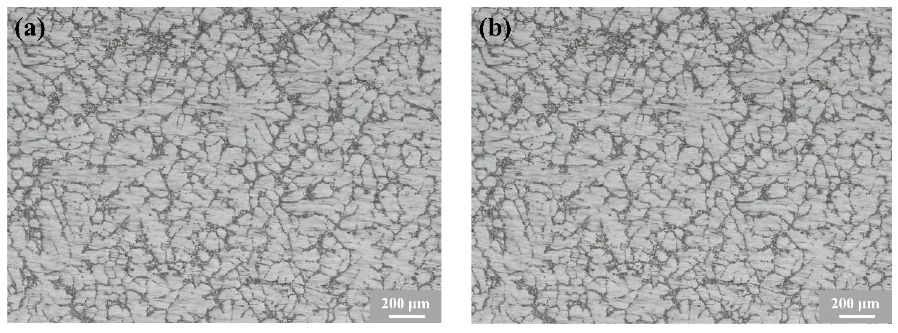
2.3. Microstructure Characterization

Metallographic images were observed by optical microscopy (OM; Leica M165C, Solms, Germany). The specimen for microstructure characterization was polished by 800#, 1500#, 2000# and 3000# sandpaper, which was subsequently etched with a 0.4% hydrofluoric acid solution. The 2D and 3D morphologies of fretting wear surfaces were investigated by optical microscope (OM, RTEC UP-5000, San Jose, CA, USA), where clear images could be obtained by adjusting the lens distance. The analysis field is the whole wear scar, and the spacing between the adjacent scanning point is about 0.002 mm. The microstructure of the damaged surface was observed by field emission scanning electron microscope (FFSEM, TESCAN S8000, Brno, Czech Republic).

3. Results and Discussion

3.1. Coefficient of Friction

The representative optical microstructures of the investigated AlSi7Mg0.6 alloy are presented in Figure 3. It can be seen that columnar grains prevailed, while Al-rich dendrites can also be clearly observed.
The samples after testing are shown in Figure 4. For each sample, the same normal load but with different sliding distances were applied. On each sample, the wear scars from top to bottom correspond to sliding distances of 0.5 mm, 1.5 mm and 3.0 mm. It is obvious that the longer the sliding distance, the larger the wear scar or the worn volume. The normal applied loads for the specimens from left to right are 20 N, 50 N, 100 N and 200 N, but it is very obscure how the wear volume develops under different normal applied loads, especially at relatively shorter sliding distance.
To quantitatively assess the fretting wear behavior of the samples, the instantaneous coefficients of friction (CoFs) between A357 aluminum alloys and GCr15 steel balls are presented in Figure 5, which demonstrate the evolution of frictional force ratio between the wear contact surfaces and the applied normal force. The CoF demonstrates the complex results of many factors such as surface condition, applied load and environment. It can be seen that, although the curves of the CoFs fluctuate with time, they tend to be a stable value ultimately. Under the same applied load, the CoF under different sliding distances tends to be the same, while the value of the CoF decreases slightly as the applied load increases from 20 N to 100 N. From 20 N to 100 N, the average CoFs are 0.51, 0.46 and 0.42, respectively. But at the applied load of 200 N, the CoF at a sliding distance of 0.5 mm is obviously higher than two of the others, which is explained in the following discussion.

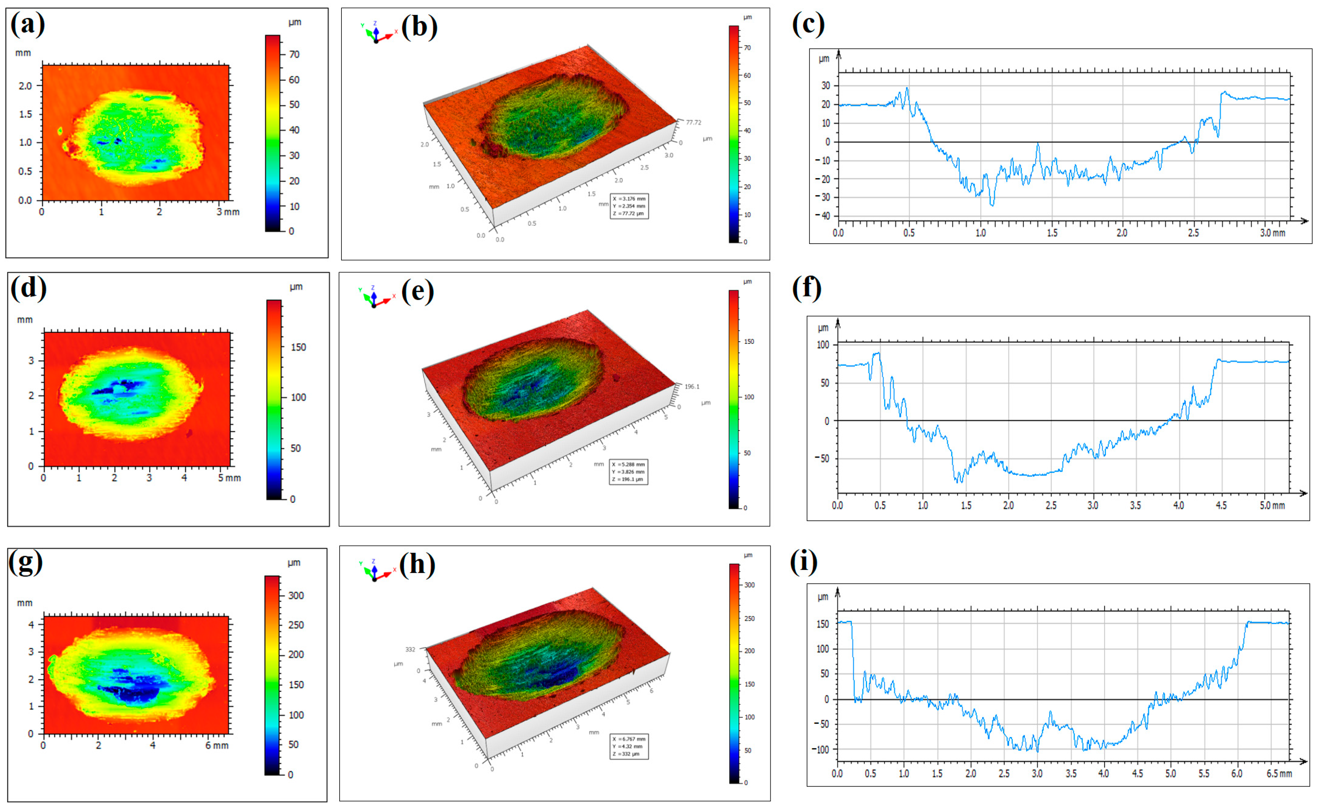
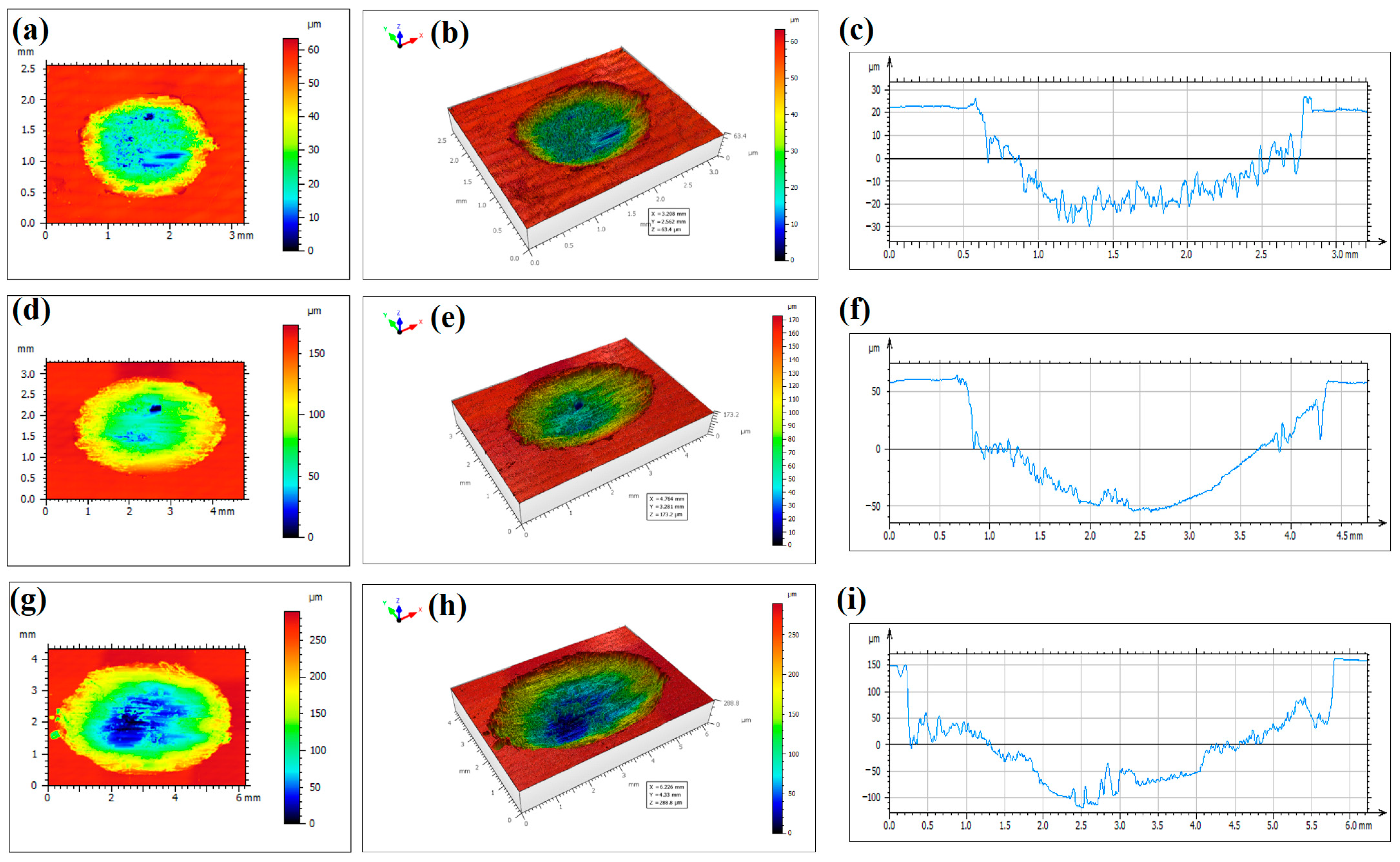
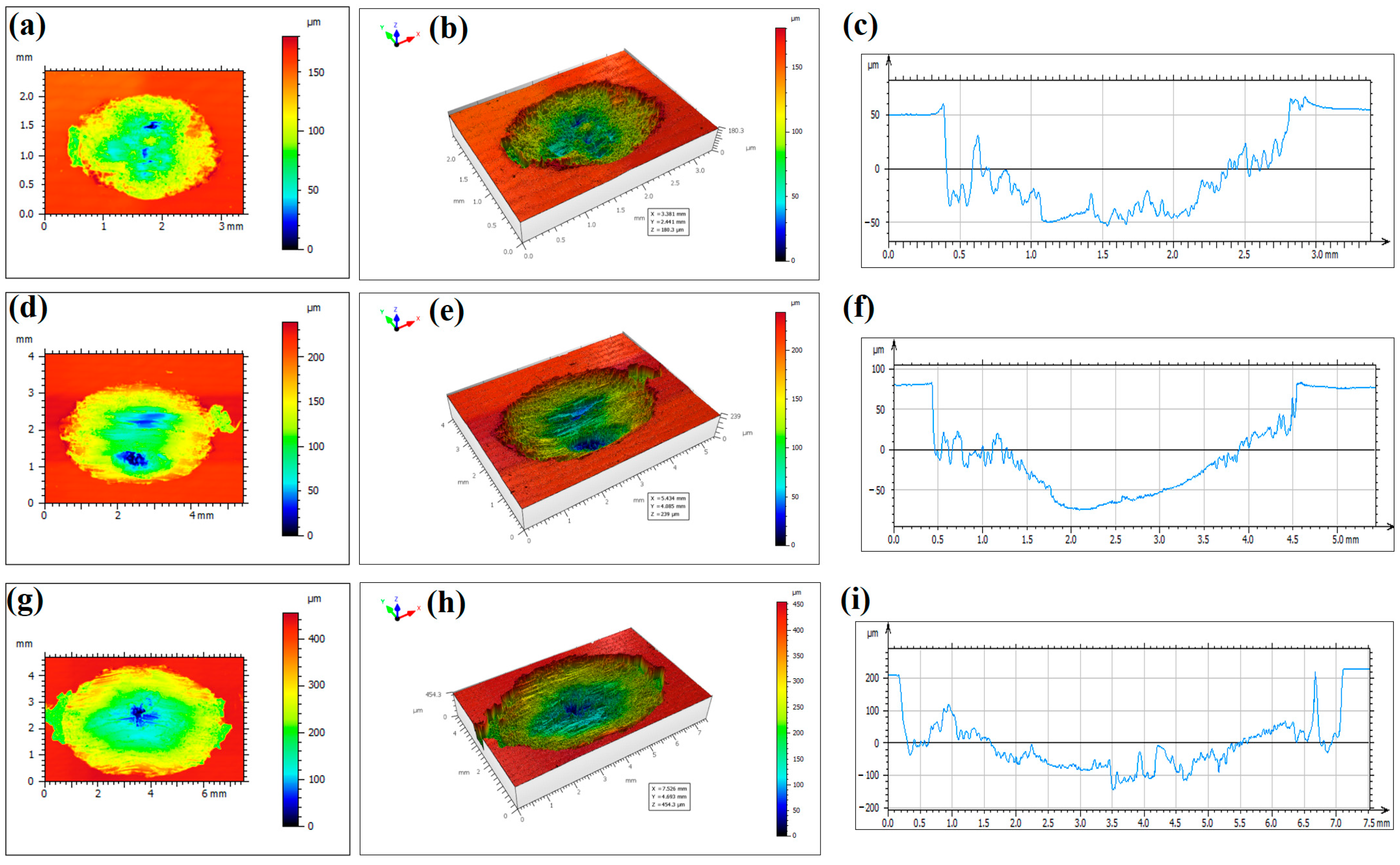
3.2. Morphologies of the Wear Scar

The 2D optical morphologies, 3D surface morphologies and cross-sectional profiles of the wear scars under different applied loads and different sliding distances are presented in Figure 6, Figure 7, Figure 8 and Figure 9. The dashed lines indicate the locations where the cross-sectional profiles are measured. Three repetitions were made for each wear scar during the research. To characterize the wear scars quantitatively, the wear volume of the samples under different normal applied loads and sliding distance is illustrated in Figure 10. At a sliding distance of 0.5 mm, it is noted that there is no obvious change of wear volume at below 100 N, and there is only a slight increase at 200 N. At a sliding distance of 1.5 mm, it is clear that the wear volume increases with applied load, while for the conditions with a sliding distance of 3.0 mm, the wear volumes are much larger than the other two sliding distances.
Under the same applied normal load, the wear volumes increase significantly with sliding distances, especially at higher applied load. The wear volumes at a sliding distance of 0.5 mm are only about 1/10 of that at a sliding distance of 3.0 mm. It can also be seen that the wear volume based on a sliding distance of 3.0 mm and applied load of 20 N is still much larger than the condition based on a sliding distance of 0.5 mm and applied load of 200 N. The results reveal that the sliding distance is much more responsible for the wear damage than that of a normal applied load. It is also suggested that rolling contact friction rather than sliding contact friction between adjacent components should be maintained during component assembling, and proper contact force should be adjusted to ensure it. Sliding contact friction should be avoided by adjusting the contact force of the components.
The detected maximum wear depth and average wear depth under different testing conditions are illustrated in Figure 10b,c, which yield the same trends as those of wear volume.

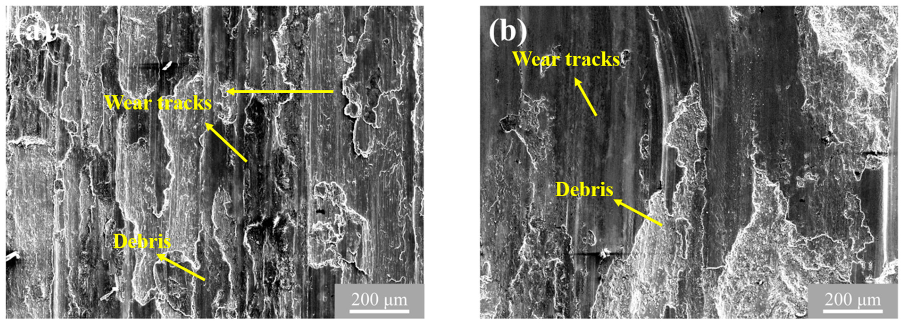
3.3. Microstructural Observation of the Wear Scar

The wear mechanism can be obtained from the microstructure of wear scars. The SEM microscopic morphologies of the abrasive wear scars in the central areas under 20 N and 200 N are exhibited in Figure 11. The sliding distance is 3 mm. Ploughing along the sliding direction prevails on the worn surface. It is noted that large plastic deformation and severe delamination damages are both observed under two applied loads. Compared with the wear surface under 200 N, more debris are found on the wear surface loaded under 20 N. It is concluded that debris formed during the reciprocating abrasive duration and mainly account for the evolution of damage process. Under larger normal applied load, the debris are much more easily peeled off from the matrix material, leading to larger wear volume. It can be seen in Figure 5d that the final CoF based on a sliding distance of 3 mm is smaller than that of 0.5 mm, where more debris are peeled off, acting as abrasive wears and reducing CoF. These conclusions can also be drawn from the results of 3D surface morphologies and quantitative wear volume measurements. The presented results reveal that abrasive wear is the main wear mechanism in the dry sliding friction conditions.

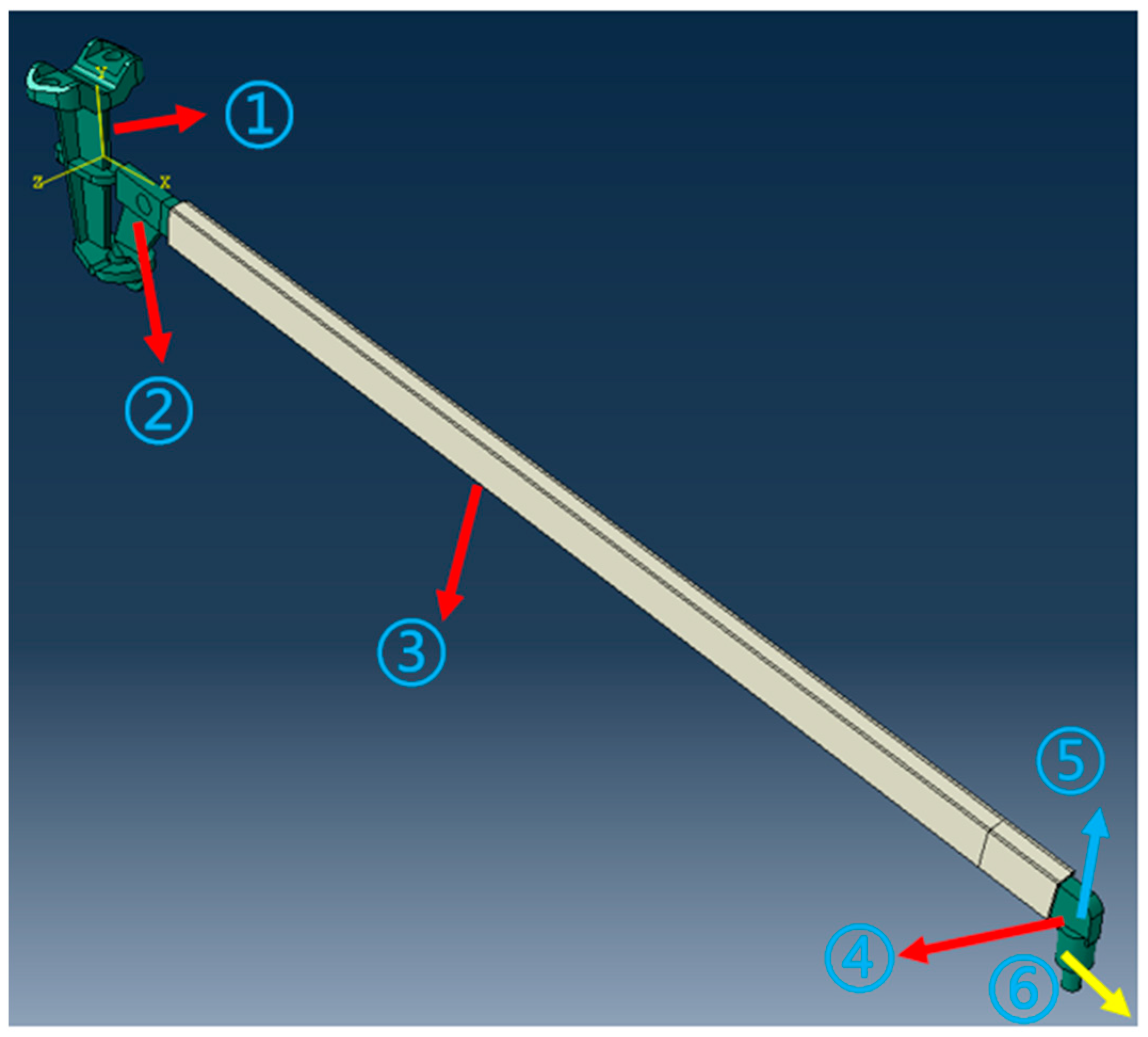
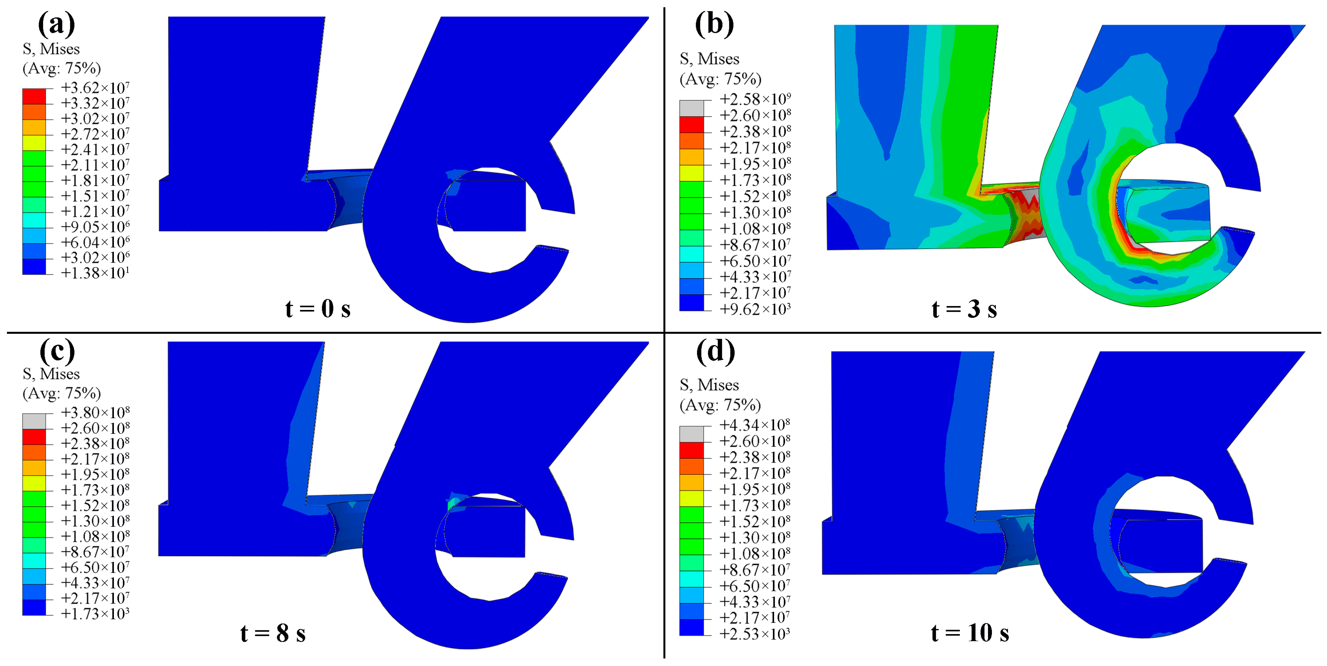
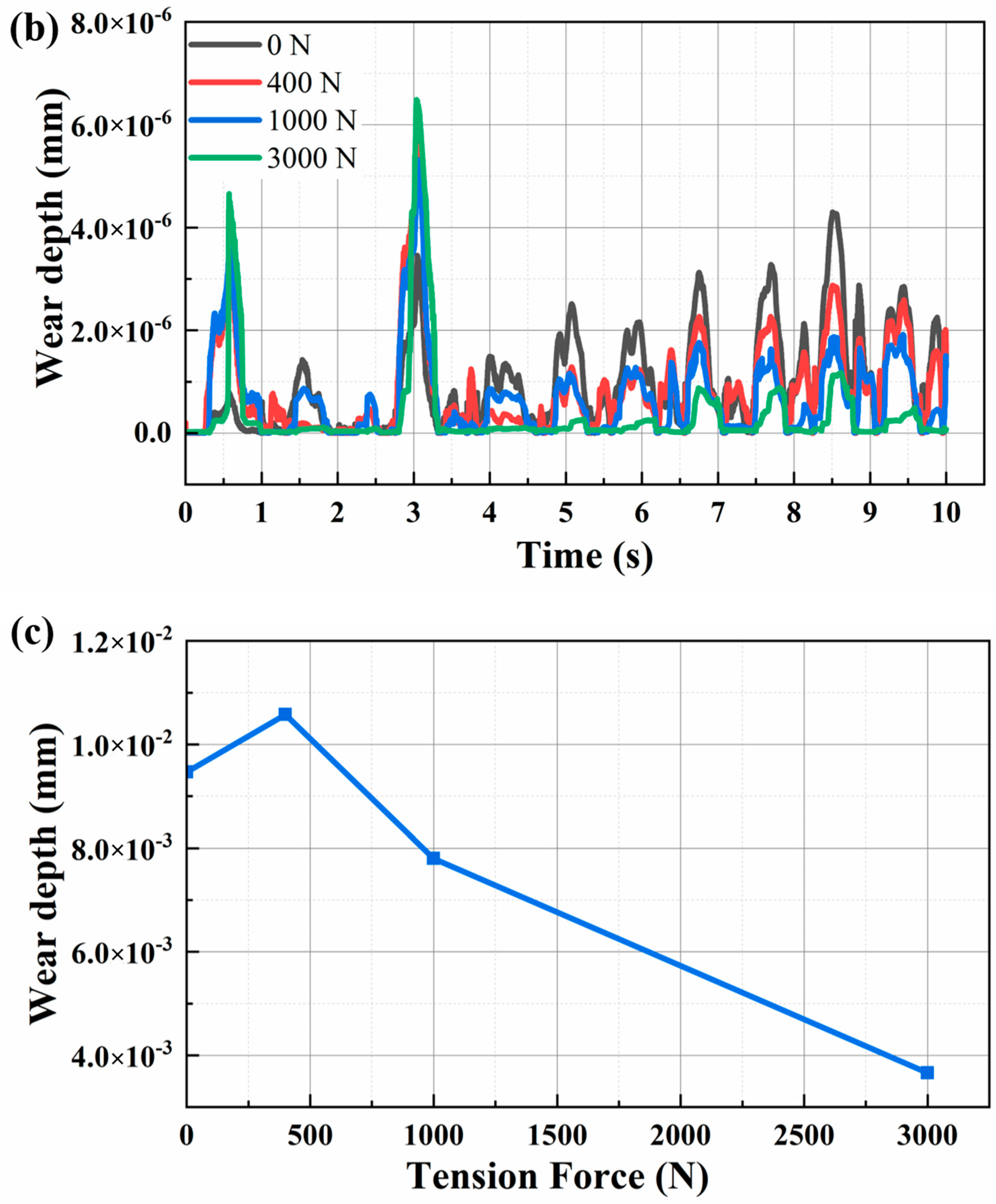
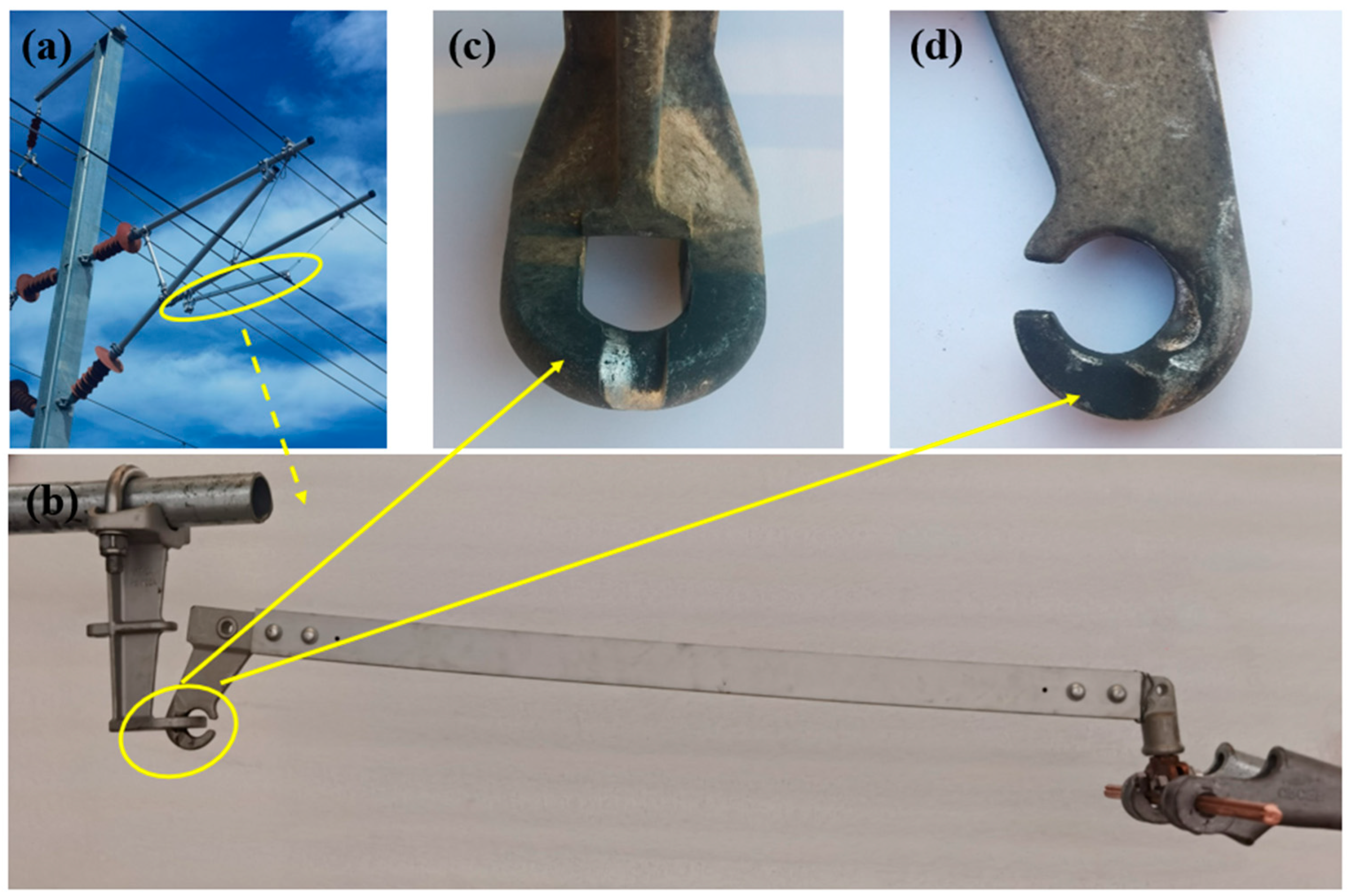
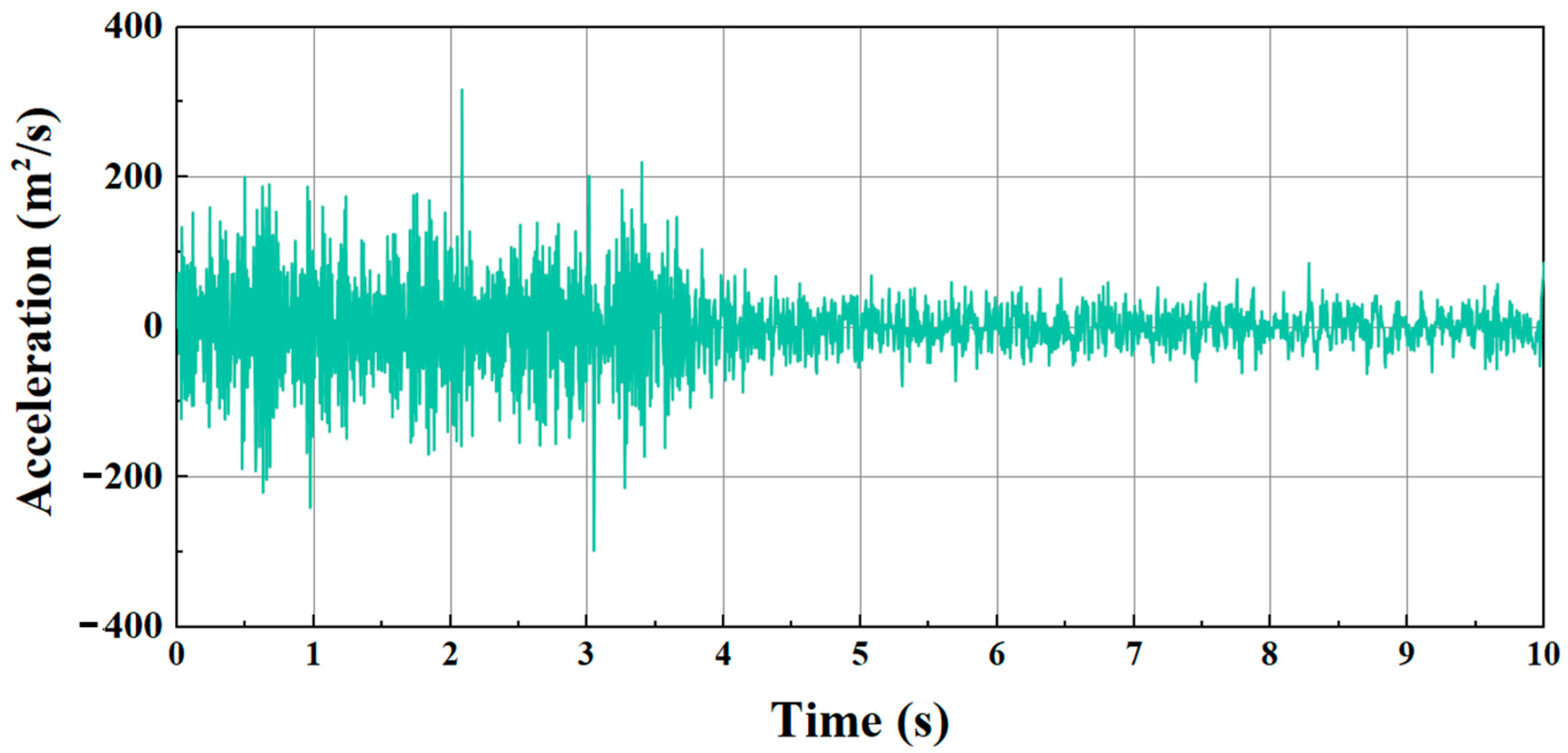
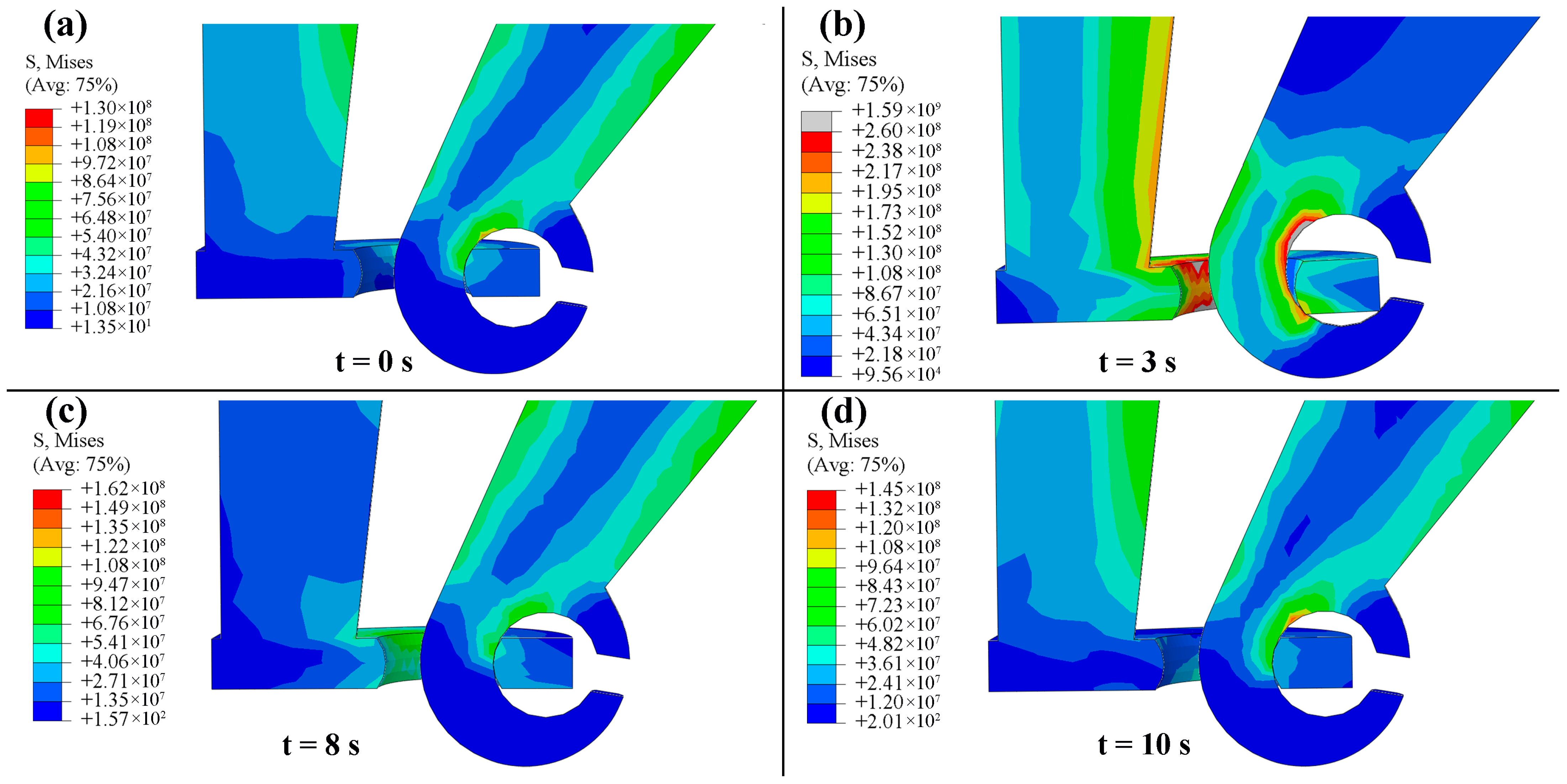
3.4. Finite-Element Analysis of Wear Behavior of Positioning Hook

To analyze the wear behavior of the positioning hook under different tension force, a numerical model was established as presented in Figure 12. Main parts including positioning hook (①), positioning support (②), steady arm (③) and positioning clamp (④) were adopted in the simulations. The steady arm is made from wrought aluminum alloy 6082 (E = 69 GPa, v = 0.34, ρ = 2700 kg/m3), while the other three parts are made from cast aluminum alloy AlSi7Mg0.6 (E = 70 GPa, v = 0.33, ρ = 2610 kg/m3). Tetrahedral mesh (C3D10M) and hexahedral mesh (C3D8R, only for the part ③) with maximum mesh sizes of 1 mm are adopted in the simulations, and the total mesh number is 587,634. In the simulations, the same impact load is applied and the upper surfaces of the positioning support are fixed. The input shocking acceleration spectrum obtained from field testing is applied on the positioning clamp in the vertical direction of ⑤, and the acceleration spectrum is given in Figure 13. Different tension force is also applied on the positioning clamp along the axial direction of the steady arm (schematized as ⑥), where tension forces of 0 N, 400 N, 1000 N and 3000 N are adopted. Tension force of 0 N suggests that it is loosened between the hook and support.
The status of the positioning devices at different times under tension forces of 400 N and 3000 N are presented in Figure 14 and Figure 15, respectively. Under tension force of 3000 N, single contact exists mostly during the impact loading process, suggesting that rolling contact friction prevails during the loading process. However, under tension force of 400 N, multiple contact points are frequently observed, indicating that sliding contact friction occurs during the impact loading process.
The wear quantity is quantitatively calculated by the Archard wear formula:
h = k p l
where h is the wear depth, p is the contact pressure, k is coefficient of friction, l is the relative sliding distance between the hook and support. Wear depth denotes the extent to which the surface material is worn off due to friction. p can be retrieved from the simulation results directly, k can be obtained from the experimental results, and these two variables do not change significantly under low- and high-tension forces. Thus, it is the variable l that determines the value of wear depth.
Relative sliding distance refers to the difference in displacement between two components undergoing relative motion. This phenomenon is commonly observed during friction, sliding, rolling or any other form of relative movement between surfaces. When sliding occurs between two objects, their surface points experience relative displacement. First, the relative sliding distance of the surface nodes and the number of corresponding nodes on the hook are extracted. Subsequently, the average relative sliding distance of the hook ring surface for each frame of results file is calculated. Then, the average values across all the frames are summed. Finally, the mean relative sliding displacement of the hook ring surface throughout the entire vibration process is obtained, which is presented in Figure 16a. Accordingly, the evolution of wear depth with time is obtained and is presented in Figure 16b. The variation of wear depth with tension force is presented in Figure 16c. It can be clearly seen that the wear depth does not change linearly with the increase in tension force and the difference in sliding distance mainly accounts for the phenomenon. The simulation results indicate that the contacting components with smaller tension force will experience larger relative sliding motion under the same shocking loading.
This numerical model is a very simple one, where the volume diminishing and mesh deforming are not considered. Materials can also be worn off under large rolling contact intrigued by high tension force, which cannot be ignored in real working conditions. These factors will be considered in future studies.

4. Conclusions

In the present study, the influences of applied load and sliding distance on abrasive wear behaviors of AlSi7Mg0.6 aluminum alloy were investigated in terms of coefficient of friction (CoF), 2D and 3D surface morphologies of wear scar, wear volume and wear mechanism. The main conclusions were drawn as follows:
(1)
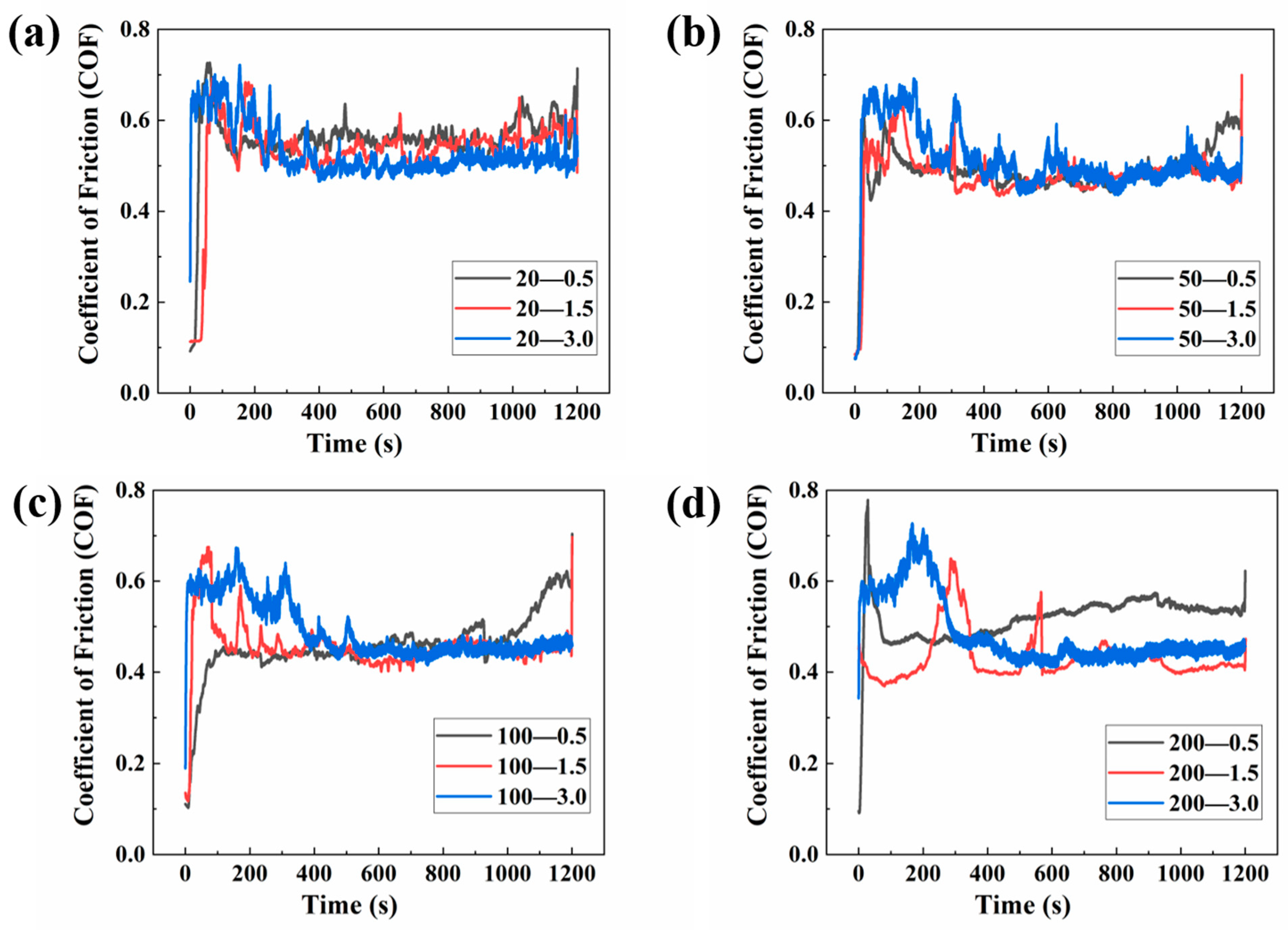
Reciprocating friction wear experiments based on three groups of sliding distance (0.5 mm, 1.5 mm and 3.0 mm) and four groups of applied loads (20 N, 50 N, 100 N and 200 N) were implemented to study the wear behavior of AlSi7Mg0.6 samples. Under the same applied load, the CoFs with different sliding distances tended to be the same. From 20 N to 100 N, the average CoFs were 0.51, 0.46 and 0.42, respectively, but at the applied load of 200 N, the CoF with a sliding distance of 0.5 mm was obviously higher than two of the other cases.
(2)
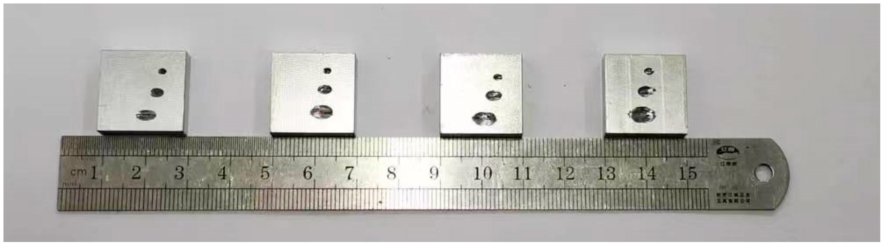
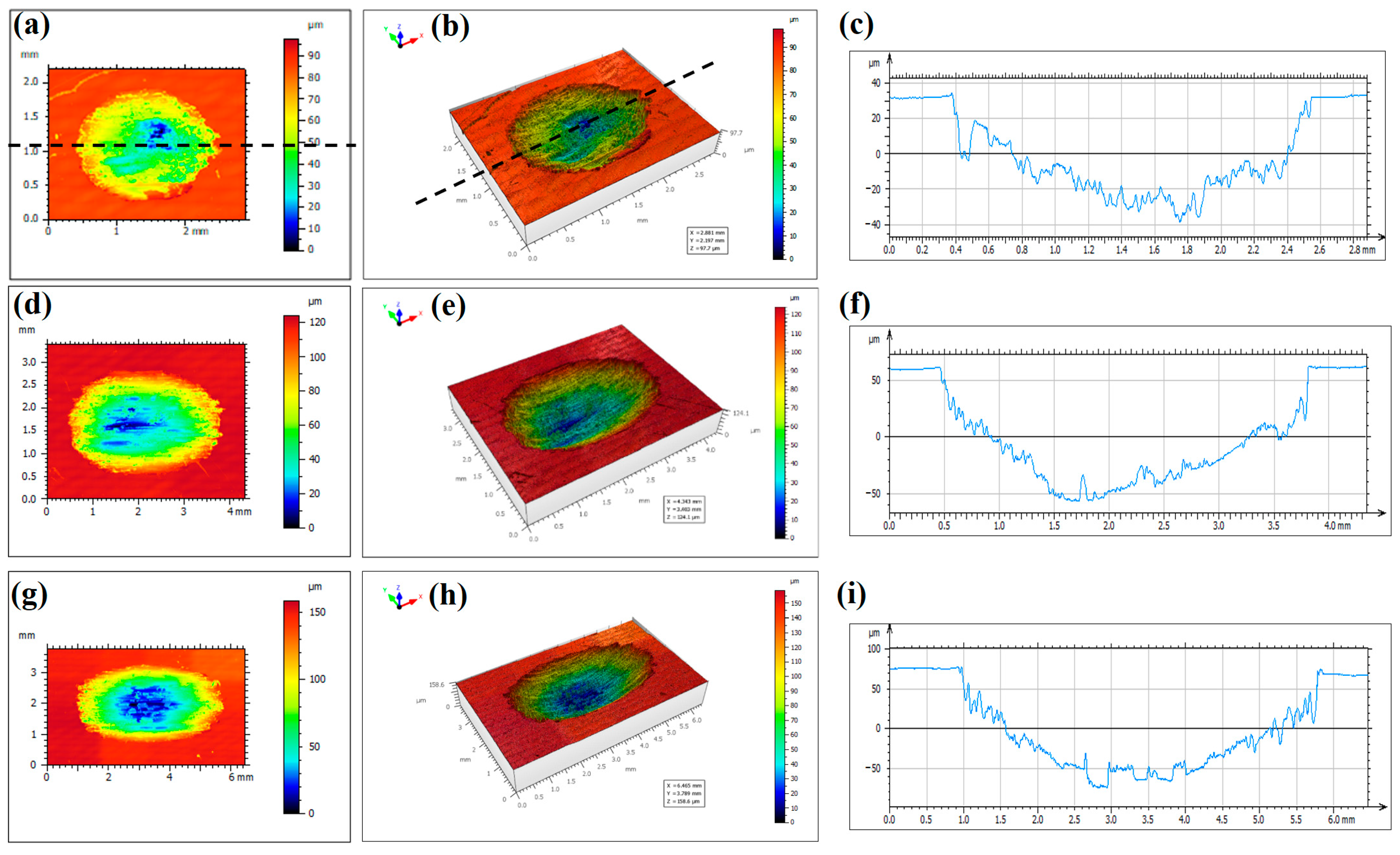
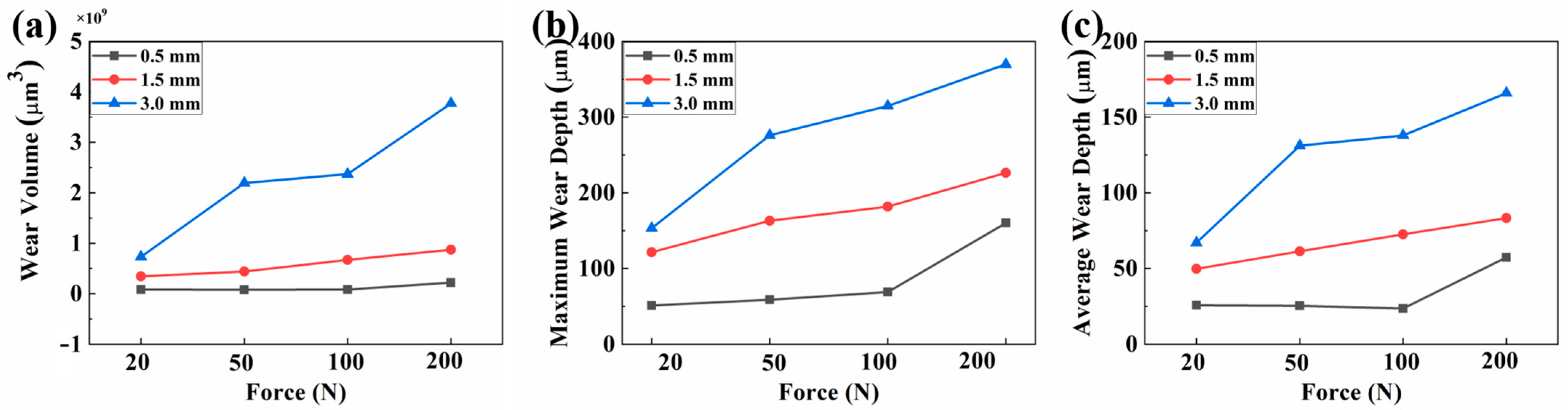
Under the same applied normal load, the wear volumes and maximum wear depth increased significantly with sliding distances, especially at higher applied load. The wear volumes at a sliding distance of 0.5 mm were only about 1/10 of that at a sliding distance of 3.0 mm. It was also revealed that the wear volume based on a sliding distance of 3.0 mm and applied load of 20 N was still much larger than the wear volume based on a sliding distance of 0.5 mm and applied load of 200 N.
(3)
SEM observation of the microstructures revealed severe plastic deformation and ploughing along the sliding direction of wear scars, where wear tracks and debris were clearly observed. Less debris were found on the worn surfaces of wear scar under an applied load of 200 N compared with that of 20 N, indicating that abrasive wear was the main wear mechanism in dry sliding friction conditions.
(4)
A simplified positioning device model was established to study the influence of tension force on wear performance. The simulation results revealed that smaller tension force would lead to higher relative sliding distance and larger wear depth under smaller tension force between the positioning support and positioning hook. The experimental and simulation results suggested that proper tension force was preferred which could ensure rolling contact friction rather than sliding contact friction. Sliding distance rather than tension force was the dominant influencing factor during the wearing process.

Author Contributions

H.Z.: Conceptualization, Methodology, Software, Writing—original draft. Y.Z.: Project administration, Supervision, Funding acquisition, Experiments. L.P.: Methodology, Software. A.Z.: Writing—review and editing. All authors have read and agreed to the published version of the manuscript.

Funding

The project is supported by the Research Project of China Academy of Railway Sciences Corporation Limited (2021YJ113).

Data Availability Statement

The data that support the findings of this study are available from the corresponding author upon reasonable request.

Acknowledgments

The authors would like to thank the editor, associate editor and the anonymous reviewers for their helpful comments and suggestions that have improved this paper.

Conflicts of Interest

The authors declare no conflict of interest.

References

  1. Liu, L.; Ding, N.; Xu, N.; Guo, W.; Shi, J.; Li, N.; Zhang, L.; Meng, B.; Zaïri, F. Failure analysis and optimization of a suspended structure in the power supply system of the subway. Eng. Fail. Anal. 2020, 115, 104619. [Google Scholar] [CrossRef]
  2. Liu, X.-Y.; Peng, J.-F.; Tan, D.-Q.; Xu, Z.-B.; Liu, J.-H.; Mo, J.-L.; Zhu, M.-H. Failure analysis and optimization of integral droppers used in high speed railway catenary system. Eng. Fail. Anal. 2018, 91, 496–506. [Google Scholar] [CrossRef]
  3. Wei, X.K.; Meng, H.F.; He, J.H.; Jia, L.M.; Li, Z.G. Wear analysis and prediction of rigid catenary contact wire and pantograph strip for railway system. Wear 2020, 442, 203118. [Google Scholar] [CrossRef]
  4. Derosa, S.; Nåvik, P.; Collina, A.; Bucca, G.; Rønnquist, A. A heuristic wear model for the contact strip and contact wire in pantograph-Catenary interaction for railway operations under 15 kV 16.67 Hz AC systems. Wear 2020, 456, 203401. [Google Scholar] [CrossRef]
  5. Yang, H.; Wang, K.; Liu, Y.; Fu, L.; Cui, X.; Jiang, G.; Hu, B. The formation of the delamination wear of the pure carbon strip and its influence on the friction and wear properties of the pantograph and catenary system. Wear 2020, 454, 203343. [Google Scholar] [CrossRef]
  6. Barros, A.; Cruz, C.; Silva, A.P.; Cheung, N.; Garcia, A.; Rocha, O.; Moreira, A. Length scale of solidification microstructure tailoring corrosion resistance and microhardness in T6 heat treatment of an Al–Cu–Mg alloy. Corros. Eng. Sci. Technol. 2020, 55, 471–479. [Google Scholar] [CrossRef]
  7. Chandra, V.S.; Krishna, K.S.V.B.R.; Ravi, M.; Sivaprasad, K.; Dhanasekaran, S.; Prashanth, K.G. Mechanical and Tribological Behavior of Gravity and Squeeze Cast Novel Al-Si Alloy. Metals 2022, 12, 194. [Google Scholar] [CrossRef]
  8. Hirsch, S.J.; Winter, L.; Grund, T.; Lampke, T. Heat Treatment Influencing Porosity and Tensile Properties of Field Assisted Sintered AlSi7Mg0.6. Materials 2022, 15, 2503. [Google Scholar] [CrossRef]
  9. Chen, R.; Xu, Q.; Guo, H.; Xia, Z.; Wu, Q.; Liu, B. Correlation of solidification microstructure refining scale, Mg composition and heat treatment conditions with mechanical properties in Al-7Si-Mg cast aluminum alloys. Mater. Sci. Eng. A 2017, 685, 391–402. [Google Scholar] [CrossRef]
  10. Silva, C.; Barros, A.; Vida, T.; Garcia, A.; Cheung, N.; Reis, D.A.P.; Brito, C. Assessing Microstructure Tensile Properties Relationships in Al-7Si-Mg Alloys via Multiple Regression. Metals 2022, 12, 1040. [Google Scholar] [CrossRef]
  11. Zhang, B.; Wei, W.; Shi, W.; Guo, Y.; Wen, S.; Wu, X.; Gao, K.; Rong, L.; Huang, H.; Nie, Z. Effect of heat treatment on the microstructure and mechanical properties of Er-containing Al-7Si-0.6Mg alloy by laser powder bed fusion. Mater. Sci. Eng. A 2019, 760, 105–117. [Google Scholar]
  12. Antoun, A.A.; Brochu, M.; Möller, H. Effect of the Rheocasting Process and of the SLS Layer on the Fatigue Behavior of 357 Aluminum Alloy. Solid State Phenom. 2014, 217, 227–234. [Google Scholar] [CrossRef]
  13. Serrano-Munoz, I.; Buffiere, J.-Y.; Verdu, C.; Gaillard, Y.; Mu, P.; Nadot, Y. Influence of surface and internal casting defects on the fatigue behaviour of A357-T6 cast aluminium alloy. Int. J. Fatigue 2016, 82, 361–370. [Google Scholar] [CrossRef]
  14. Dezecot, S.; Brochu, M. Microstructural characterization and high cycle fatigue behavior of investment cast A357 aluminum alloy. Int. J. Fatigue 2015, 77, 154–159. [Google Scholar] [CrossRef]
  15. Santos, J.; Zhu, B.; Zanella, C.; Jarfors, A.E.W. Fatigue Crack Initiation on Semi-Solid Al–7Si–Mg Castings. Metals 2022, 12, 1061. [Google Scholar] [CrossRef]
  16. Elleuch, K.; Fouvry, S. Wear analysis of A357 aluminium alloy under fretting. Wear 2002, 253, 662–672. [Google Scholar] [CrossRef]
  17. Yang, C.-Y.; Lee, S.-L.; Lee, C.-K.; Lin, J.-C. Effects of Sr and Sb modifiers on the sliding wear behavior of A357 alloy under varying pressure and speed conditions. Wear 2006, 261, 1348–1358. [Google Scholar] [CrossRef]
  18. Chandrashekharaiah, T.M.; Kori, S.A. Effect of grain refinement and modification on the dry sliding wear behaviour of eutectic Al–Si alloys. Tribol. Int. 2009, 42, 59–65. [Google Scholar] [CrossRef]
  19. Çolak, M.; Arslan, İ. Investigation of the effect of the addition of grain refiner and modifier addition on wear properties in sand and permanent mould casting of A357 and A380 aluminium alloys. Int. J. Cast Met. Res. 2022, 35, 17–23. [Google Scholar] [CrossRef]
  20. Lorenzetti, L.; Tonelli, L.; Ceschini, L.; Liverani, E.; Martini, C. A357 aluminium alloy produced by LPBF: Tribological behaviour in dry sliding conditions. Wear 2022, 510–511, 204488. [Google Scholar] [CrossRef]
  21. Lakshmikanthan, A.; Prabhu, T.R.; Babu, U.S.; Koppad, P.G.; Gupta, M.; Krishna, M.; Bonth, S. The effect of heat treatment on the mechanical and tribological properties of dual size SiC reinforced A357 matrix composites. J. Mater. Res. Technol. 2020, 9, 6434–6452. [Google Scholar] [CrossRef]
  22. Tan, D.; Xia, S.; Yob, A.; Yang, K.; Yan, S.; Givord, M.; Liang, D. Evaluation of the wear resistance of aluminium-based hybrid composite brake discs under relevant city rail environments. Mater. Des. 2022, 215, 110504. [Google Scholar] [CrossRef]
  23. Shalaby, E.A.M.; Churyumov, Y.A. Development and characterization of A359/AlN composites for automotive applications. J. Alloys Compounds 2017, 727, 540–548. [Google Scholar] [CrossRef]
  24. Shalaby, E.A.M.; Churyumov, Y.A.; Solonin, A.N.; Lotfy, A. Preparation and characterization of hybrid A359/(SiCþSi3N4) composites synthesized by stir/squeeze casting techniques. Mat. Sci. Eng. A 2016, 674, 18–24. [Google Scholar] [CrossRef]
  25. Lu, Z.; Wang, P.; Zhang, D. Super-hydrophobic film fabricated on aluminium surface as a barrier to atmospheric corrosion in a marine environment. Corros. Sci. 2015, 91, 287–296. [Google Scholar] [CrossRef]
  26. Sato, Y.; Iwabuchi, A.; Uchidate, M.; Yashiro, H. Dynamic corrosion properties of impact–fretting wear in high-temperature pure water. Wear 2015, 330–331, 182–192. [Google Scholar] [CrossRef]
  27. Zhu, B.; Zanella, C. Hardness and corrosion behaviour of anodized Al-Si produced by rheocasting. Mater. Des. 2019, 173, 107764. [Google Scholar] [CrossRef]
  28. Yang, C.-Y.; Lee, S.-L.; Lee, C.-K.; Lin, J.-C. Effects of Be and Fe on the mechanical and corrosion behaviors of A357 alloys. Mater. Chem. Phys. 2005, 93, 412–419. [Google Scholar] [CrossRef]
  29. Osório, W.R.; Goulart, P.R.; Garcia, A. Effect of silicon content on microstructure and electrochemical behavior of hypoeutectic Al–Si alloys. Mater. Lett. 2008, 62, 365–369. [Google Scholar] [CrossRef]
  30. Milošev, I.; Kapun, B.; Rodič, P.; Carrière, C.; Mercier, D.; Zanna, S.; Marcus, P. Mechanism of Corrosion of Cast Aluminum-Silicon Alloys in Seawater. Part 1: Characterization and Field Testing of Bare Alloys in the Adriatic Sea. Corrosion 2023, 79, 193–212. [Google Scholar] [CrossRef]
  31. Milošev, I.; Kapun, B.; Rodič, P.; Carrière, C.; Mercier, D.; Zanna, S.; Marcus, P. Mechanism of Corrosion of Cast Aluminum-Silicon Alloys in Seawater. Part 2: Characterization and Field Testing of Sol-Gel-Coated Alloys in the Adriatic Sea. Corrosion 2023, 79, 213–229. [Google Scholar] [CrossRef] [PubMed]
  32. Lai, F.; Qu, S.; Lewis, R.; Slatter, T.; Fu, W.; Li, X. The influence of ultrasonic surface rolling on the fatigue and wear properties of 23-8N engine valve steel. Int. J. Fatigue 2019, 125, 299–313. [Google Scholar] [CrossRef]
  33. Gangopadhyay, A.; McWatt, D.G. The effect of novel surface textures on tappet shims on valvetrain friction and wear. Tribol. T. 2008, 51, 221–230. [Google Scholar] [CrossRef]
  34. Pellizzari, M.; Molinari, A.; Straffelini, G. Thermal fatigue resistance of gas and plasma nitrided 41CrAlMo7 steel. Mat. Sci. Eng. A 2003, 352, 186–194. [Google Scholar] [CrossRef]
  35. Tang, J.; Hu, X.; Lai, F.; Guo, X.; Qu, S.; He, R.; Qin, S.; Li, J. Evolution of Fretting Wear Behaviors and Mechanisms of 20CrMnTi Steel after Carburizing. Metals 2020, 10, 179. [Google Scholar] [CrossRef]
  36. Tan, D.-Q.; Mo, J.-L.; He, W.-F.; Luo, J.; Zhang, Q.; Zhu, M.-H.; Zhou, Z.-R. Suitability of laser shock peening to impact-sliding wear in different system Stiffnesses. Surf. Coat. Technol. 2019, 358, 22–35. [Google Scholar] [CrossRef]
  37. Fernandez-Lopez, P.; Alves, S.A.; Azpitarte, I.; San-Jose, J.T.; Bayon, R. Corrosion and tribocorrosion protection of novel PEO coatings on a secondary cast Al-Si alloy: Influence of polishing and sol-gel sealing. Corros. Sci. 2022, 207, 110548. [Google Scholar] [CrossRef]
  38. Liu, X.; An, Y.; Li, S.; Zhao, X.; Hou, G.; Zhou, H.; Chen, J. An assessment of tribological performance on NiCoCrAlYTa coating under corrosive environments. Tribology Int. 2017, 115, 35–44. [Google Scholar] [CrossRef]
  39. Liu, Y.; Mol, J.M.C.; Janssen, G.C.A.M. Corrosion reduces wet abrasive wear of structural steel. Scr. Mater. 2015, 107, 92–95. [Google Scholar] [CrossRef]
  40. Dalbert, V.; Mary, N.; Normand, B.; Verdu, C.; Douillard, T.; Saedlou, S. The effects of microstructures and repassivation kinetics on the tribocorrosion resistance of ferrite and ferrite-martensite stainless steels. Wear 2019, 420, 245–256. [Google Scholar] [CrossRef]
  41. Liu, Y.; Liu, L.; Li, S.; Wang, R.; Guo, P.; Wang, A.; Ke, P. Accelerated deterioration mechanism of 316L stainless steel in NaCl solution under the intermittent tribocorrosion process. J. Mater. Sci. Technol. 2022, 121, 67–79. [Google Scholar] [CrossRef]
  42. Wang, Y.; Hao, E.; An, Y.; Hou, G.; Zhao, X.; Zhou, H. The interaction mechanism of cavitation erosion and corrosion on HVOF sprayed NiCrWMoCuCBFe coating in artificial seawater. Appl. Surf. Sci. 2020, 525, 146499. [Google Scholar] [CrossRef]
  43. Wang, Y.; Zhao, X.; Xue, Y.; An, Y.; Zhou, H.; Chen, J. Effect of the microstructure of corrosion products on tribo-corrosion performance of HVOF-sprayed NiCrWMoCuCBFe coating. Corros. Sci. 2022, 207, 110597. [Google Scholar] [CrossRef]
  44. Chen, G.; Wang, X.; Wang, J.; Liu, J.; Zhang, T.; Tang, W. Damage investigation of the aged aluminium cable steel reinforced (ACSR) conductors in a high-voltage transmission line. Eng. Fail. Anal. 2012, 19, 13–21. [Google Scholar] [CrossRef]
  45. Ma, X.; Gao, L.; Zhang, J.; Zhang, L.-C. Fretting Wear Behaviors of Aluminum Cable Steel Reinforced (ACSR) Conductors in High-Voltage Transmission Line. Metals 2017, 7, 373. [Google Scholar] [CrossRef]
Figure 1. (a) Schematic of catenary system of high-speed railway. (b) Drawing of a steady arm, positioning hook and positioning support. Wear failure of positioning hook (c) and positioning support (d).
Metals 13 01628 g001
Figure 2. Reciprocating friction and wear experimental instrument. (a) Overall profile of the instrument. (b) Upper-sample indenter and reciprocating platform.
Metals 13 01628 g002
Figure 3. Optical microstructures of the investigated AlSi7Mg0.6 alloy. (a) Section 1. (b) Section 2.
Metals 13 01628 g003
Figure 4. Comparison of worn pits under different applied loads and sliding distance. The sliding distances from top to bottom are 0.5 mm, 1.5 mm and 3.0 mm. The applied loads from left to right are 20 N, 50 N, 100 N and 200 N.
Metals 13 01628 g004
Figure 5. The instantaneous coefficient of friction (CoF) between AlSi7Mg0.6 and GCr15 steel ball under different normal loads and sliding distance. (a) 20 N. (b) 50 N. (c) 100 N. (d) 200 N. “0.5”, “1.5” and “3.0” indicate the sliding distances and the unit is “mm”. Black lines correspond to a sliding distance of 0.5 mm, red lines correspond to a sliding distance of 1.5 mm, and blue lines correspond to a sliding distance of 3.0 mm.
Metals 13 01628 g005
Figure 6. 2D optical morphologies, 3D surface morphologies and cross-sectional profiles of the wear scars under different sliding distances and applied load of 20 N. (ac) 0.5 mm. (df) 1.5 mm. (gi) 3.0 mm. The dashed lines indicate the locations where the cross-sectional profiles are measured.
Metals 13 01628 g006
Figure 7. 2D optical morphologies, 3D surface morphologies and cross-sectional profiles of the wear scars under different sliding distances and applied load of 50 N. (ac) 0.5 mm. (df) 1.5 mm. (gi) 3.0 mm.
Metals 13 01628 g007
Figure 8. 2D optical morphologies, 3D surface morphologies and cross-sectional profiles of the wear scars under different sliding distances and applied load of 100 N. (ac) 0.5 mm. (df) 1.5 mm. (gi) 3.0 mm.
Metals 13 01628 g008
Figure 9. 2D optical morphologies, 3D surface morphologies and cross-sectional profiles of the wear scars under different sliding distances and applied load of 200 N. (ac) 0.5 mm. (df) 1.5 mm. (gi) 3.0 mm.
Metals 13 01628 g009
Figure 10. Quantitative measurements of the wear scars on the worn surfaces under different normal applied loads and sliding distance. (a) Wear volume. (b) Maximum wear depth. (c) Average wear depth.
Metals 13 01628 g010
Figure 11. SEM images of wear tracks on the worn surfaces after abrasive experiments under different applied loads and a sliding distance of 3 mm. (a) 20 N. (b) 200 N.
Metals 13 01628 g011
Figure 12. Numerical modelling of the positioning facilities. ① denotes the positioning support, ② denotes the positioning hook, ③ denotes the steady arm, ④ denotes the positioning clamp, ⑤ denotes the vertical shock when the trains pass by, ⑥ denotes the horizontal tension force by electric wires.
Metals 13 01628 g012
Figure 13. Input acceleration spectrum adopted in the numerical simulation, which was recorded in a field test when the trains passed by.
Metals 13 01628 g013
Figure 14. Magnified states of positioning support and positioning hook under a tension force of 400 N at different times. (a) t = 0 s. (b) t = 3 s. (c) t = 8 s. (d) t = 10 s.
Metals 13 01628 g014
Figure 15. Magnified states of positioning support and positioning hook under a tension force of 3000 N. (a) t = 0 s. (b) t = 3 s. (c) t = 8 s. (d) t = 10 s.
Metals 13 01628 g015
Figure 16. (a) Evolution of relative sliding distance between the positioning hook and positioning support under different tension force. (b) Evolution of wear depth under different tension force. (c) Variation of wear depth with tension force.
Metals 13 01628 g016aMetals 13 01628 g016b
Table 1. Chemical compositions of the tested AlSi7Mg0.6 alloy samples (wt. %).
SiFeCuMnMgAlZnTiOthers
7.4460.1570.0040.0020.65591.510.0650.1510.01
Disclaimer/Publisher’s Note: The statements, opinions and data contained in all publications are solely those of the individual author(s) and contributor(s) and not of MDPI and/or the editor(s). MDPI and/or the editor(s) disclaim responsibility for any injury to people or property resulting from any ideas, methods, instructions or products referred to in the content.

