
Graphite/Epoxy-Coated Flaky FeSiCr Powders with Enhanced Microwave Absorption

 ,
,  ,
,  and
and
Abstract
:1. Introduction
2. Materials and Methods
3. Results and Discussion
4. Conclusions
Author Contributions
Funding
Data Availability Statement
Conflicts of Interest
References
- Pang, H.; Duan, Y.; Huang, L.; Song, L.; Liu, J.; Zhang, T.; Yang, X.; Liu, J.; Ma, X.; Di, J.; et al. Research advances in composition, structure and mechanisms of microwave absorbing materials. Compos. Part B 2021, 224, 109173. [Google Scholar] [CrossRef]
- Peng, K.; Liu, C.; Wu, Y.; Fang, G.; Xu, G.; Zhang, Y.; Wu, C.; Yan, M. Understanding the efficient microwave absorption for FeCo@ZnO flakes at elevated temperatures a combined experimental and theoretical approach. J. Mater. Sci. Technol. 2022, 125, 212–221. [Google Scholar] [CrossRef]
- Wang, B.; Wu, Q.; Fu, Y.; Liu, T. A review on carbon/magnetic metal composites for microwave absorption. J. Mater. Sci. Technol. 2021, 86, 91–109. [Google Scholar] [CrossRef]
- Weng, X.; Li, B.; Zhang, Y.; Lv, X.; Gu, G. Synthesis of flake shaped carbonyl iron/reduced graphene oxide/polyvinyl pyrrolidone ternary nanocomposites and their microwave absorbing properties. J. Alloys Compd. 2017, 695, 508–519. [Google Scholar] [CrossRef]
- Zhang, X.; Guo, Y.; Ali, R.; Tian, W.; Liu, Y.; Zhang, L.; Wang, X.; Zhang, L.; Yin, L.; Su, H.; et al. Bifunctional carbon-encapsulated FeSiAl hybrid flakes for enhanced microwave absorption properties and analysis of corrosion resistance. J. Alloys Compd. 2020, 828, 154079. [Google Scholar] [CrossRef]
- Chen, Y.; Wang, L.; Xiong, H.; Rehman, S.; Tan, Q.; Huang, Q.; Zhong, Z. Optimized Absorption Performance of FeSiCr Nanoparticles by Changing the Shape Anisotropy. Phys. Status Solidi A 2020, 217, 2000389. [Google Scholar] [CrossRef]
- Wang, L.; Xiong, H.; Rehman, S.; Tan, Q.; Chen, Y.; Zhang, L.; Yang, J.; Wu, F.; Zhong, M.; Zhong, Z. Microwave absorbing property enhancement of FeSiCr nanomaterials by regulating nanoparticle size. J. Alloys Compd. 2019, 803, 631–636. [Google Scholar] [CrossRef]
- Acher, O.; Adenot, A. Bounds on the dynamic properties of magnetic materials. Phys. Rev. B 2000, 62, 11324. [Google Scholar] [CrossRef]
- Walser, R.; Win, W.; Valanju, P. Shape-optimized ferromagnetic particles with maximum theoretical microwave susceptibility. IEEE Trans. Magn. 1998, 34, 1390–1392. [Google Scholar] [CrossRef]
- Guan, Z.; Wang, Z.; Jiang, J.; Gong, Y.; Yao, Y.; Zhen, L. Flaky FeSi particles with tunable size, morphology and microstructure developing for high-efficiency and broadband absorbing materials. J. Magn. Magn. Mater. 2021, 527, 167800. [Google Scholar] [CrossRef]
- Yang, W.; Zhang, Y.; Qiao, G.; Lai, Y.; Liu, S.; Wang, C.; Han, J.; Du, H.; Zhang, Y.; Yang, Y.; et al. Tunable magnetic and microwave absorption properties of Sm1.5Y0.5Fe17-xSix and their composites. Acta Mater. 2018, 145, 331–336. [Google Scholar] [CrossRef]
- Duan, Y.; Pang, H.; Wen, X.; Zhang, X.; Wang, T. Microwave absorption performance of FeCoNiAlCr0.9 alloy powders by adjusting the amount of process control agent. J. Mater. Sci. Technol. 2020, 77, 209–216. [Google Scholar] [CrossRef]
- Min, D.; Zhou, W.; Qing, Y.; Luo, F.; Zhu, D. Highly oriented flake carbonyl iron/carbon fiber composite as thin-thickness and wide-bandwidth microwave absorber. J. Alloys Compd. 2018, 744, 629–636. [Google Scholar] [CrossRef]
- Peng, K.; Wu, Y.; Liu, C.; Xu, G.; Fang, G.; Zhang, Y.; Cao, Y.; Zhang, Y. The tunable microwave absorption performance of the oriented flaky Fe-Co-Nd with a broad bandwidth absorption at a thin thickness. J. Magn. Magn. Mater. 2020, 510, 166925. [Google Scholar] [CrossRef]
- Zhou, X.; Jia, Z.; Zhang, X.; Wang, B.; Wu, W.; Liu, X.; Xu, B.; Wu, G. Controllable synthesis of Ni/NiO@porous carbon hybrid composites towards remarkable electromagnetic wave absorption and wide absorption bandwidth. J. Mater. Sci. Technol. 2021, 87, 120–132. [Google Scholar] [CrossRef]
- Tian, W.; Zhang, X.; Guo, Y.; Mu, C.; Zhou, P.; Yin, L.; Zhang, L.; Zhang, L.; Lu, H.; Jian, X.; et al. Hybrid silica-carbon bilayers anchoring on FeSiAl surface with bifunctions of enhanced anti-corrosion and microwave absorption. Carbon 2021, 173, 185–193. [Google Scholar] [CrossRef]
- Ren, Y.; Zhang, Y.; Zheng, Q.; Wang, L.; Jiang, W. Integrating large specific surface area and tunable magnetic loss in Fe@C composites for lightweight and high-efficiency electromagnetic wave absorption. Carbon 2023, 206, 226–236. [Google Scholar] [CrossRef]
- He, N.; Yang, X.; Shi, L.; Yang, X.; Lu, Y.; Tong, G.; Wu, W. Chemical conversion of Cu2O/PPy core-shell nanowires (CSNWs): A surface/interface adjustment method for high-quality Cu/Fe/C and Cu/Fe3O4/C CSNWs with superior microwave absorption capabilities. Carbon 2020, 166, 205–217. [Google Scholar] [CrossRef]
- Liu, Z.; Wang, Y.; Jia, Z.; Ling, M.; Yan, Y.; Chai, L.; Du, H.; Wu, G. In situ constructed honeycomb-like NiFe2O4@Ni@C composites as efficient electromagnetic wave absorber. J. Colloid Interface Sci. 2022, 608, 2849–2859. [Google Scholar] [CrossRef]
- Shen, Z.; Yang, H.; Xiong, Z.; Xie, Y.; Liu, C. Hollow core-shell CoNi@C and CoNi@NC composites as high-performance microwave absorbers. J. Alloys Compd. 2021, 871, 159574. [Google Scholar] [CrossRef]
- Ge, J.; Liu, S.; Liu, L.; Cui, Y.; Meng, F.; Li, Y.; Zhang, X.; Wang, F. Optimizing the electromagnetic wave absorption performance of designed hollow CoFe2O4/CoFe@C microspheres. J. Mater. Sci. Technol. 2021, 81, 190–202. [Google Scholar] [CrossRef]
- Li, Q.; Tan, J.; Wu, Z.; Wang, L.; You, W.; Wu, L.; Che, R. Hierarchical magnetic-dielectric synergistic Co/CoO/RGO microspheres with excellent microwave absorption performance covering the whole X band. Carbon 2023, 201, 150–160. [Google Scholar] [CrossRef]
- Zhao, H.; Wang, F.; Cui, L.; Xu, X.; Han, X.; Du, Y. Composition optimization and microstructure design in MOFs-derived magnetic carbon-based microwave absorbers: A review. Nano-Micro Lett. 2021, 13, 208. [Google Scholar] [CrossRef] [PubMed]
- Yang, X.; Duan, Y.; Li, S.; Huang, L.; Pang, H.; Ma, B.; Wang, T. Constructing three-dimensional reticulated carbonyl iron/carbon foam composites to achieve temperature-stable broadband microwave absorption performance. Carbon 2022, 188, 376–384. [Google Scholar] [CrossRef]
- Zhang, Z.; Li, Y.; Liao, Y.; Rong, H.; Zhang, W.; Zhang, M.; Qin, G.; Zhang, X. Synthesizing CNx heterostructures on ferromagnetic nanoparticles for improving microwave absorption property. Appl. Surf. Sci. 2021, 564, 150480. [Google Scholar] [CrossRef]
- Chen, J.; Lei, W.; Huang, C.; Wang, J.; Zhang, Y.; Liu, Z.; Xu, Z.; Wang, K.; Guo, S. Magneto-electric adjustable Co/C porous layer coated flaky carbonyl iron composites with bifunctions of anti-corrosion and microwave absorption. J. Alloys Compd. 2022, 927, 167104. [Google Scholar] [CrossRef]
- Wu, Z.; Cheng, H.; Jin, C.; Yang, B.; Xu, C.; Pei, K.; Zhang, H.; Yang, Z.; Che, R. Dimensional design and core–shell engineering of nanomaterials for electromagnetic wave absorption. Adv. Mater. 2022, 34, 2107538. [Google Scholar] [CrossRef]
- Cheng, J.; Zhang, H.; Xiong, Y.; Gao, L.; Wen, B.; Raza, H.; Wang, H.; Zheng, G.; Zhang, D.; Zhang, H. Construction of multiple interfaces and dielectric/magnetic heterostructures in electromagnetic wave absorbers with enhanced absorption performance: A review. J. Mater. 2021, 7, 1233–1263. [Google Scholar] [CrossRef]
- Wang, F.; Dong, Y.; Chang, L.; Pan, Y.; Chi, Q.; Gong, M.; Li, J.; He, A.; Wang, X. High performance of Fe-based soft magnetic composites coated with novel nano-CaCO3/epoxy nanocomposites insulating layer. J. Solid State Chem. 2021, 304, 122634. [Google Scholar] [CrossRef]
- Wang, Q.; Niu, B.; Han, Y.; Zheng, Q.; Li, L.; Cao, M. Nature-inspired 3D hierarchical structured “vine” for efficient microwave attenuation and electromagnetic energy conversion device. Chem. Eng. J. 2022, 452, 139042. [Google Scholar] [CrossRef]
- Feng, Y.; Xia, L.; Ding, C.; Yan, H.; Xu, G.; Zhang, T.; Xiong, L.; Qin, C.; Wen, G. Boosted multi-polarization from silicate-glass@rGO doped with modifier cations for superior microwave absorption. J. Colloid Interface Sci. 2021, 593, 96–104. [Google Scholar] [CrossRef] [PubMed]
- Wang, L.; Yu, X.; Li, X.; Zhang, J.; Wang, M.; Che, R. Conductive-network enhanced microwave absorption performance from carbon coated defect-rich Fe2O3 anchored on multi-wall carbon nanotubes. Carbon 2019, 15, 298–308. [Google Scholar] [CrossRef]
- Yan, L.; Wang, Y.; Li, W.; Liao, Z.; Wang, X.; Huang, W.; Zhang, L.; Li, Y. Lightweight and salt spray corrosion resistant porous SiC/FeSiCr hybrids for enhanced microwave absorption in the C-band. J. Alloys Compd. 2022, 907, 164467. [Google Scholar] [CrossRef]
- Ma, Z.; Cao, C.; Liu, Q.; Wang, J. A New Method to Calculate the Degree of Electromagnetic Impedance Matching in One-Layer Microwave Absorbers. Chin. Phys. Lett. 2012, 29, 038401. [Google Scholar] [CrossRef]
- Hu, J.; Liu, S.; Wang, Y.; Ju, W.; He, N.; He, J.; Jia, H.; Xia, C.; Huang, Z.; Long, J.; et al. Manganese phosphate coated flaky FeSiAl powders with enhanced microwave absorbing properties and improved corrosion resistance. Mater. Chem. Phys. 2023, 296, 127274. [Google Scholar] [CrossRef]
- Lu, B.; Huang, H.; Dong, X.; Zhang, X.; Lei, J.; Sun, J.; Dong, C. Influence of alloy components on electromagnetic characteristics of core/shell-type Fe–Ni nanoparticles. J. Appl. Phys. 2008, 104, 114313. [Google Scholar] [CrossRef]
- Huynen, I. Investigation of microwave absorption mechanisms in microcellular foamed conductive composites. Micro 2021, 1, 86–101. [Google Scholar] [CrossRef]
- Li, T.; Wang, C.; An, Y.; Xia, Y.; Wang, X.; Huang, X. Tunable and ultraefficient microwave absorptivity in SnO2/Sn/rGO composites via enhanced polarization effect. J. Alloys Compd. 2022, 930, 167250. [Google Scholar] [CrossRef]
- Li, Q.; Guo, W.; Kong, X.; Xu, J.; Xu, C.; Chen, Y.; Chen, J.; Jia, X.; Ding, Y. MnFe2O4/rGO/Diatomite composites with excellent wideband electromagnetic microwave absorption. J. Alloys Compd. 2023, 941, 168851. [Google Scholar] [CrossRef]
- Fu, X.; Zheng, Q.; Li, L.; Cao, M. Vertically implanting MoSe2 nanosheets on the RGO sheets towards excellent multi-band microwave absorption. Carbon 2022, 197, 324–333. [Google Scholar] [CrossRef]
- Ma, Y.; Li, Y.; Zhao, X.; Zhang, L.; Wang, B.; Nie, A.; Mu, C.; Xiang, J.; Zhai, K.; Xue, T.; et al. Lightweight and multifunctional super-hydrophobic aramid nanofiber/multiwalled carbon nanotubes/Fe3O4 aerogel for microwave absorption, thermal insulation and pollutants adsorption. J. Alloys Compd. 2022, 919, 165792. [Google Scholar] [CrossRef]
- Zhang, M.; Qian, C.; Zhu, R.; Liu, H.; Zhang, Y.; Liu, Q. Flower-like MoS2 self-assembled on multiferroic Z-type Sr3Co2Fe24O41 hexaferrite for ultra-wideband microwave absorption. J. Alloys Compd. 2022, 926, 166881. [Google Scholar] [CrossRef]

| Materials | Loading | RLmin | EABmax | References |
|---|---|---|---|---|
| FeCoNiAlCr0.9 | 50 wt.% | −29.7 dB@2 mm | 4.28 GHz@2 mm | [12] |
| Fe@CNx | 50 wt.% | −26.8 dB | - | [25] |
| SnO2/Sn/rGO | 5 wt.% | −39.5 dB@3.0 mm | - | [38] |
| MnFe2O4/rGO/ Diatomite | 80 wt.% | −76.6 dB@2.5 mm | 3.61 GHz@2.5 mm | [39] |
| MoSe2@rGO | 40 wt.% | −56.9 dB@8.9 mm | 4.12 GHz@8.9 mm | [40] |
| ANF/MWCNT/Fe3O4 | - | −45.8 dB@3.7 mm | 4.0 GHz@1.4 mm | [41] |
| Sr3Co2Fe24O41/MoS2 | 60 wt.% | −44.5 dB@3.0 mm | 3.92 GHz@3.0 mm | [42] |
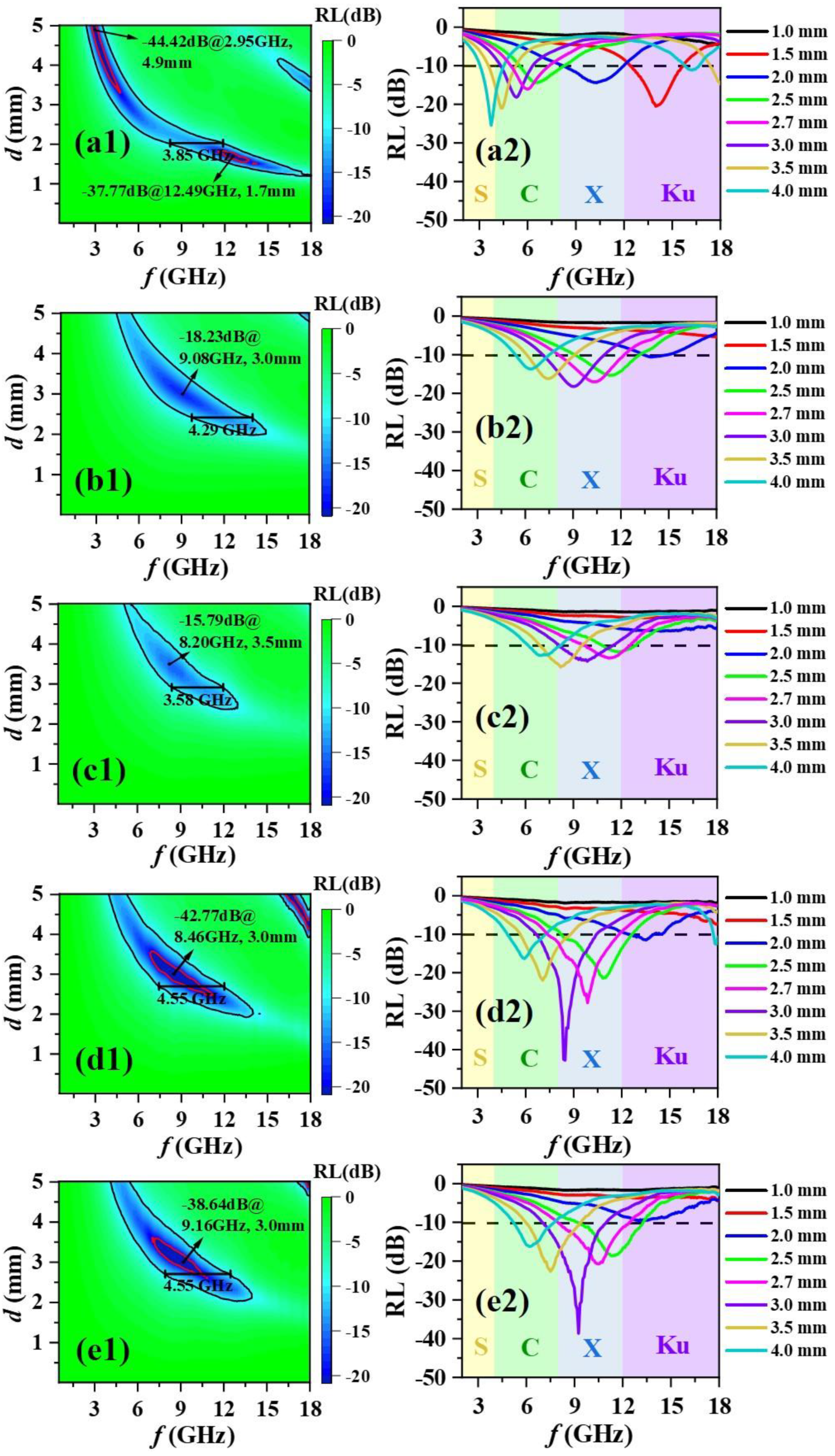
| FFSC@G2000/E | 30 wt.% | −42.8 dB@3.0 mm | 4.55 GHz@2.7 mm | This work |
| FFSC@G5000/E | 30 wt.% | −38.6 dB@3.0 mm | 4.55 GHz@2.7 mm | This work |
Disclaimer/Publisher’s Note: The statements, opinions and data contained in all publications are solely those of the individual author(s) and contributor(s) and not of MDPI and/or the editor(s). MDPI and/or the editor(s) disclaim responsibility for any injury to people or property resulting from any ideas, methods, instructions or products referred to in the content. |
© 2023 by the authors. Licensee MDPI, Basel, Switzerland. This article is an open access article distributed under the terms and conditions of the Creative Commons Attribution (CC BY) license (https://creativecommons.org/licenses/by/4.0/).
Share and Cite
Zhang, H.; Zhong, X.; Hu, J.; He, N.; Xu, H.; Liao, X.; Zhou, Q.; Liu, Z.; Ramanujan, R.V. Graphite/Epoxy-Coated Flaky FeSiCr Powders with Enhanced Microwave Absorption. Metals 2023, 13, 1611. https://doi.org/10.3390/met13091611
Zhang H, Zhong X, Hu J, He N, Xu H, Liao X, Zhou Q, Liu Z, Ramanujan RV. Graphite/Epoxy-Coated Flaky FeSiCr Powders with Enhanced Microwave Absorption. Metals. 2023; 13(9):1611. https://doi.org/10.3390/met13091611
Chicago/Turabian StyleZhang, Haonan, Xichun Zhong, Jinwen Hu, Na He, Hanxing Xu, Xuefeng Liao, Qing Zhou, Zhongwu Liu, and Raju V. Ramanujan. 2023. "Graphite/Epoxy-Coated Flaky FeSiCr Powders with Enhanced Microwave Absorption" Metals 13, no. 9: 1611. https://doi.org/10.3390/met13091611
APA StyleZhang, H., Zhong, X., Hu, J., He, N., Xu, H., Liao, X., Zhou, Q., Liu, Z., & Ramanujan, R. V. (2023). Graphite/Epoxy-Coated Flaky FeSiCr Powders with Enhanced Microwave Absorption. Metals, 13(9), 1611. https://doi.org/10.3390/met13091611