Article

Analysis of Microstructure Evolution of Co-Cr-Mo Alloy during Isothermal Forging

by
Yury V. Gamin
1,*,
Alexander V. Skugorev
1,
Mukhamed M. Karashaev
1,
Tatiana Y. Kin
1,
Sergei P. Galkin
1,
Abdullah Mahmoud Alhaj Ali
1 and
Vladimir V. Cheverikin
2
1
Department of Metal Forming, National University of Science and Technology «MISIS» (NUST MISIS), 4 Leninsky Pr., 119049 Moscow, Russia
2
Department of Physical Chemistry, Moscow State University (MSU), Leninskiye Gory, 1, 119991 Moscow, Russia
*
Author to whom correspondence should be addressed.
Metals 2023, 13(9), 1583; https://doi.org/10.3390/met13091583
Submission received: 16 August 2023 / Revised: 7 September 2023 / Accepted: 8 September 2023 / Published: 12 September 2023
(This article belongs to the Section Metal Casting, Forming and Heat Treatment)

Abstract

:
The article analyzes the microstructure evolution of Co-Cr-Mo alloy during isothermal forging. The process of isothermal forging can be a technological solution to produce a semi-finished product for subsequent deformation processing and obtain a high-quality microstructure that excludes casting defects. Based on analysis of microstructure and phase composition and calculations, the required modes of ingot homogenization are determined. Finite element method simulation of the forging has shown that temperature and deformation conditions make deformation in the single-phase γ-region possible. However, at lower temperatures, σ-phase particles may precipitate at the last steps of deformation. After isothermal forging and water quenching, a mixture of recrystallized and polygonized structures with an average grain size of 5–10 μm and precipitation of ultra-fine dispersed particles of σ-phase (~0.13 μm) at grain boundaries are formed. Isothermal forging in the temperature range of 1100–1200 °C and at low strain rates of up to 1 s−1 allows obtaining a microstructure without pores, cracks, and large inclusions. Thus, it makes it possible to use the forging billet for further deformation by different metal forming methods.

1. Introduction

Co-Cr-Mo alloys are among the advanced materials used in medicine to produce different implants and their components. While in service in the human body, these implants are subjected to cyclic loads, corrosion environments, and significant wear [1,2,3]. Co-Cr-Mo alloys are characterized by high values of mechanical properties combined with good resistance to corrosion and wear [4,5,6]. In addition, these alloys have an acceptable level of biocompatibility [7]. Titanium alloys are often the first-choice materials for implants because of their lower elastic modulus and higher biocompatibility. However, titanium alloys are significantly inferior in resistance to wear to Co-Cr-Mo alloys, which is especially important in the manufacture of sliding pairs [8].
Mechanical properties of Co-Cr-Mo alloys depend largely on chemical composition, in particular additions of carbon and nitrogen, production method (casting or deformation processes), and conditions of heat treatment [9,10,11,12]. A series of research studies devoted to the study of Co-Cr-Mo alloys have shown that the presence of intermetallic σ-phase and carbide precipitation had a significant effect on their mechanical properties. In cast alloys, the σ-phase is present as interdendritic inclusions along the grain boundaries and has a tetragonal structure consisting of an intermetallic compound of the Co(Cr,Mo) type [13,14]. This phase is undesirable in materials due to the characteristic embrittlement effect, leading to a decrease in mechanical properties. The subsequent deformation process of cast alloys without initial heat treatment directed to the dissolution of the σ-phase can lead to defect formation and even workpiece fracture. The presence of σ-phase in deformed semi-finished products results in a decrease in ductility [15,16]. Moreover, the microstructure and mechanical properties of Co-Cr-Mo alloys are specified by their phase composition, particularly the volume fractions of γ-phase (fcc) and ε-phase (hcp). In this case, the conditions of the γ→ε phase transformation depend on the chemical composition and heat treatment methods of the alloy. Additionally, it can be induced by deformation processes during metal forming [17,18,19].
The selection of the processing method for Co-Cr-Mo alloy has a great impact on its mechanical properties and microstructure. Casting is the most used method for the production of the semi-finished product of surgery implants. However, the strength and especially the ductility of cast alloy have low values, and the microstructure is characterized by coarse grains [20]. In addition, cast billets may have axial porosity and gas micro and macro cavities. To improve the mechanical properties, the use of a deformed workpiece is most preferable. The technological process for obtaining semi-finished products from Co-Cr-Mo alloys can be carried out by hot forging operations [12,21]. However, hot forging using high-speed equipment can lead to the formation of defects, such as cracks in the axial zone of the workpiece and instability of the deformation process. The use of isothermal forging makes it possible to avoid these defects, since the temperature of the working tool is close to the temperature of the deformed workpiece. For this reason, there is no rapid cooling of the workpiece, and a relatively homogeneous structure is formed [22,23]. In [24], isothermal forging (compression) was studied for laboratory samples (small cylindrical billets 10 mm high and 7 mm in diameter). These dimensions differ significantly from the dimensions of industrial billets, which are commensurate with the dimensions of real products. In addition, the tests were conducted at low strain rates (10−1–10−4 s−1), which are also typically much lower than strain rates in industrial metal forming processes.
It was noted in [25,26] that a uniform fine-grained structure formed in samples of the Co-Cr-Mo alloy when tested for uniaxial compression led to improved mechanical properties. In addition, according to the research, the formation of an ultra-fine-grained structure in the alloy was a consequence of past dynamic recrystallization (DRX). Many factors influence the kinetics of DRX, including stacking fault energy (SFE), conditions of thermomechanical treatment (TMT), initial grain size, chemical composition of the material, precipitation of the secondary phases, and others [27,28,29]. Earlier, the study of the deformation behavior of Co-Cr-Mo alloy and the construction of processing maps for the determination of temperature–speed parameters of hot deformation were carried out [30]. It has been shown that the most optimal thermo-deformation modes are low strain rates of less than 5 s−1 and temperatures above 1100 °C. Thus, isothermal forging can be a technological solution for the production of an intermediate product for subsequent deformation processing and obtaining a high-quality microstructure that excludes casting defects.
The main objective of this paper is to study the microstructure evolution during isothermal forging of Co-Cr-Mo alloy. To select the deformation modes and analyze the temperature conditions of isothermal forging, finite element modeling (FEM) was used.

2. Materials and Methods

2.1. Experimental Procedure

The ingot produced by vacuum-induction melting method was used as the initial workpiece. The chemical composition of the ingot, defined by X-ray fluorescence and gas analysis, is presented in Table 1 (the standard deviation of determination of chemical composition was 1% for each element). The chemical composition was in accordance with requirements of [31].
The machined ingot with a diameter of 75 mm was subjected to homogenization at a temperature of 1250 °C in a vacuum furnace with the possibility of rapid cooling. The ingot was cooled in a nitrogen flow under pressure to provide the maximum cooling rate.
After homogenization, the ingot was forged using an isothermal press with a force of 16 MN. The forging was carried out by flat open dies heated to a temperature of 950 ± 10 °C. The use of heated dies makes it possible to minimize heat losses of the workpiece and carry out the forging under quasi-isothermal conditions.
Before the forging process, the ingot was heated to a temperature of 1200 ± 10 °C. Isothermal forging was carried out according to the following scheme (Figure 1a).
  • Radial forging to obtain a 65 × 65 mm square cross-section;
  • Intermediate heating at temperature of 1200 ± 10 °C, holding time 20 min;
  • Upsetting with a deformation degree of ~30%;
  • Radial forging to obtain a 60 × 60 mm square cross-section;
  • Upsetting with a deformation degree of ~30%;
  • Radial forging to obtain a round 55 mm cross-section;
  • Water quenching.
The forged billet from Co-Cr-Mo alloy before rapid water cooling is shown in Figure 1b.

2.2. FEM Simulation Model

A finite element method (FEM) simulation was carried out using the QForm 3D software package (QForm version 9.0.10, QuantorForm LLS, Moscow, Russia) [32]. A cylinder with a diameter of 75 mm and a length of 180 mm was used as the initial workpiece, which was deformed for several steps in accordance with the modes shown in Figure 1a.
To solve the plasticity problem, the stress–strain curves at different temperatures and strain rates obtained after compression tests with Gleeble 3800 equipment were used (Figure 2).
The workpiece was deformed along its entire length by two heated flat plates with a diameter of 900 mm. To solve the thermal problem, the conditions of heat transfer between workpiece with tool and workpiece with ambient environment were established. The tool and workpiece were specified as having rigid and plastic bodies, respectively. After isothermal forging, the quenching process for 360 s was also simulated. The relative error of simulated results did not exceed 10%. The main simulation parameters are presented in Table 2.
Based on the simulation results, the distribution of temperature, strain rate, and triaxiality parameters were analyzed. The triaxiality parameter is calculated as follows:
η = σ m σ e f f ,
where σ m is an average stress and MPa and σ e f f is an effective stress, MPa.

2.3. Analysis of Microstructure and Phase Composition

To evaluate the critical points of the material under study, the phase composition of the Co-Cr-Mo alloy was defined using the JMatPro [33] (Java-based Materials Property simulation software, version 7.0.0) (Sente Software Ltd., Surrey Technology Center, 40 Occam Road, Guildford, Surrey GU2 7YG, Guildford, UK), as well as the method of differential thermal analysis (DTA) when heating samples in helium at a rate of 20 °C/min on a Linseis DTA PT 1600/700LT. The error of temperature determination was ±3 °C.
X-ray diffraction (XRD) analysis of initial homogenized ingot and forged bar samples was performed on a Rigaku PSF-3M universal X-ray diffractometer (Rigaku Corporation, The Woodlands, TX, USA) in Cu-Kα radiation in the range of angles of (2θ) 20–90° with a step of 0.02° and exposure per point of 1 s.
Microstructure analysis was carried out by optical microscopy (OM, Carl Zeiss Microscopy GmbH, Oberkochen, Germany), scanning electron microscopy (SEM, EMPA, Tescan, Brno, Czech Republic), and electron backscatter diffraction (EBSD) for regions in the center and near the surface of forged billet. For EBSD analysis, a TESCAN VEGA LMH with a LaB6 cathode (SEM), X-ray energy-dispersive (EDS) microanalysis system (Oxford Instruments Advanced AZtecEnergy, Abingdon, Oxfordshire, UK), and NordLysMax2 Oxford Instruments with AZtec version 3.5 software was used. To identify materials and phases, various databases such as Oxford Instruments database of pure elements and organic substances and NIST database of phases and elements were used. Scanning was carried out with a step of 0.4 µm. Data processing of structure parameters by EBSD analysis was carried out using the HKL Channel5 Oxford Instruments software (Oxford Instruments, Abingdon, Oxfordshire, UK), which includes modules Tango, Mambo, and Salsa.
The sample’s surface was prepared by grinding with different abrasive disks and polishing. Then, the samples were subjected to electrolytic etching in a solution of methanol and sulfuric acid (9:1) at operating voltage of 9V for 1–2 min.

3. Results and Discussion

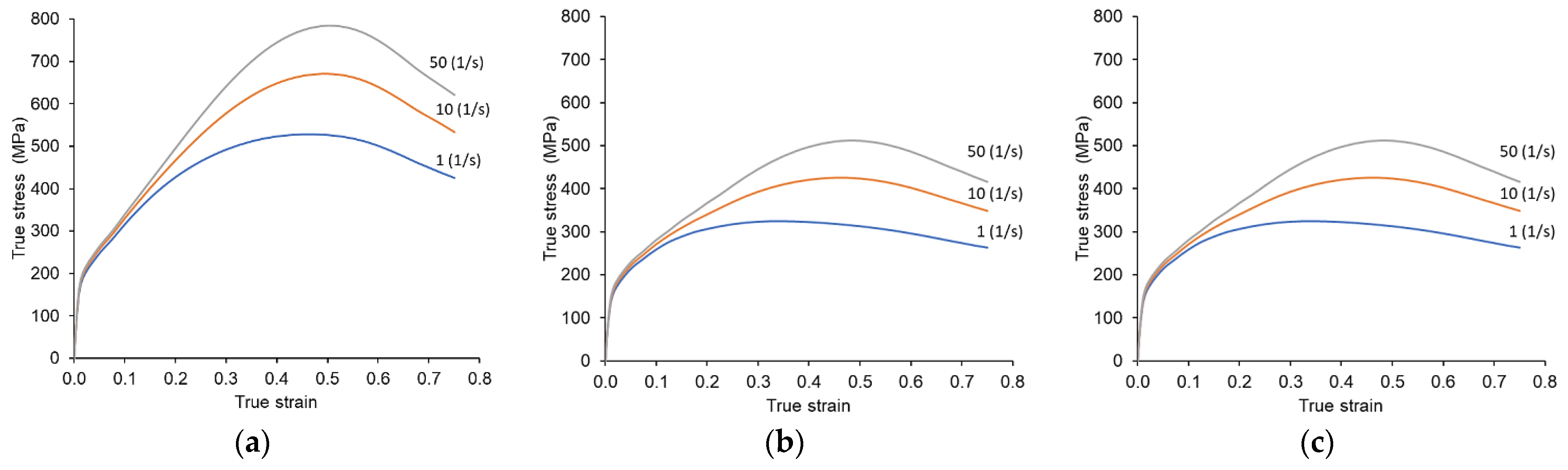
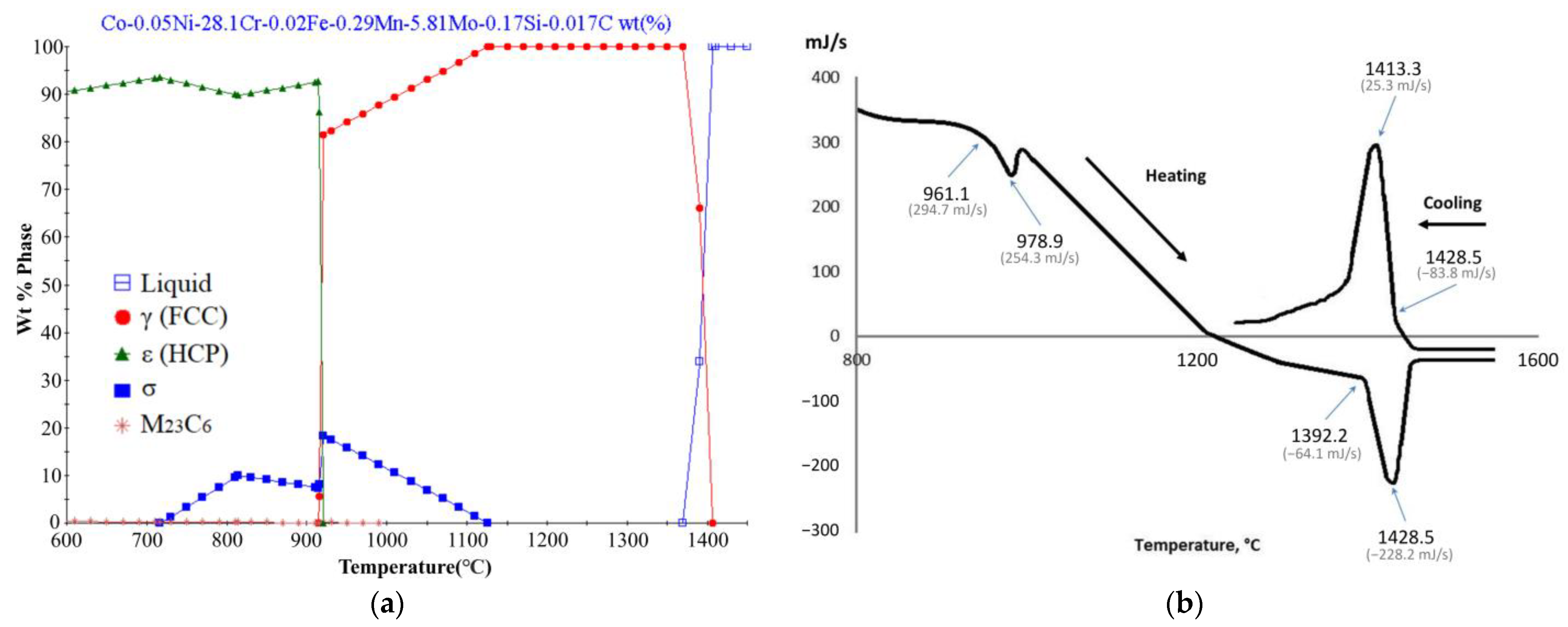
3.1. Justification of Selection of Heat Treatment and Deformation Processing

The phase diagram of Co-Cr-Mo alloy in the temperature range of 600–1450 °C constructed using the JMatPro program is shown in Figure 3a.
According to the data calculated, the crystallization of the alloy occurred at a temperature of ~1393 °C. Then, at cooling below a temperature of 1125 °C, the σ-phase precipitated from a solid solution of γ-matrix. Its volume fraction was small at these temperatures and equal to ~4.66 wt.% at the decrease in temperature to 1100 °C. As the alloy cooled, the volume fraction of the σ-phase increased and achieved a value of 19.7 wt.%. at a temperature of ~921 °C. As the temperature decreased, the proportion of the σ-phase gradually decreased and completely disappeared at 700 °C.
At a temperature of ~921°C, the beginning of a polymorphic transformation of the matrix γ-phase with the fcc lattice into the ε-phase with the hcp lattice (γ→ε) was observed. Further, according to calculation, at temperatures below 700 °C, the stable phase was the ε-phase with the hcp lattice and an insignificant number of carbides of the Me23C6 type (less than 0.3% wt.).
The DTA curve of the sample cut out from the ingot of Co-Cr-Mo alloy after homogenization is presented in Figure 3b. The following temperature peaks were successively recorded at the heating range of the sample up to a temperature of 1428 °C: at a temperature of ~962 °C, 980 °C, and 1392 °C and 1428 °C, respectively. It followed from the obtained data that the temperature range ~962–980 °C was that for the polymorphic transformation γ→ε. The temperatures 1392 °C and 1428 °C were the solidus and liquidus temperatures, respectively. The temperatures on the cooling curve during the crystallization of the alloy practically coincided with the temperatures during heating and were equal: solidus −1413 °C and liquidus −1428 °C. The difference in the solidus temperature during heating and cooling of ~20 °C can be associated with the consumption of surface energy during the formation of a solid phase.
Critical temperature points of the studied alloy are presented in Table 3.
The deviation of the calculated values of critical temperatures from the experimental data can be caused by both the simulation error and the local chemical inhomogeneity of the sample for DTA.
To select the homogenization mode, the calculation of the change in concentration of alloying elements over the dendritic cell (150 µm) section was carried out using the JMatPro software package. The calculation results for the main alloying elements (Cr and Mo) at homogenization temperatures of 1200 °C and 1250 °C and different holding times are shown in Figure 4.
It can be seen from the obtained calculation results that the leveling of the concentration of Cr and Mo in the center of the dendrite and at the boundary of the dendritic cell occurred at a temperature of 1250 °C and a holding time of at least 9 h. The homogenization mode of the ingot from Co-Cr-Mo alloy was selected to account for the obtained results.
The heating temperature of the ingot before forging was chosen as the maximum possible for the available furnaces to ensure the forging in the temperature range is not lower than the polymorphic transformation temperature γ→ε.

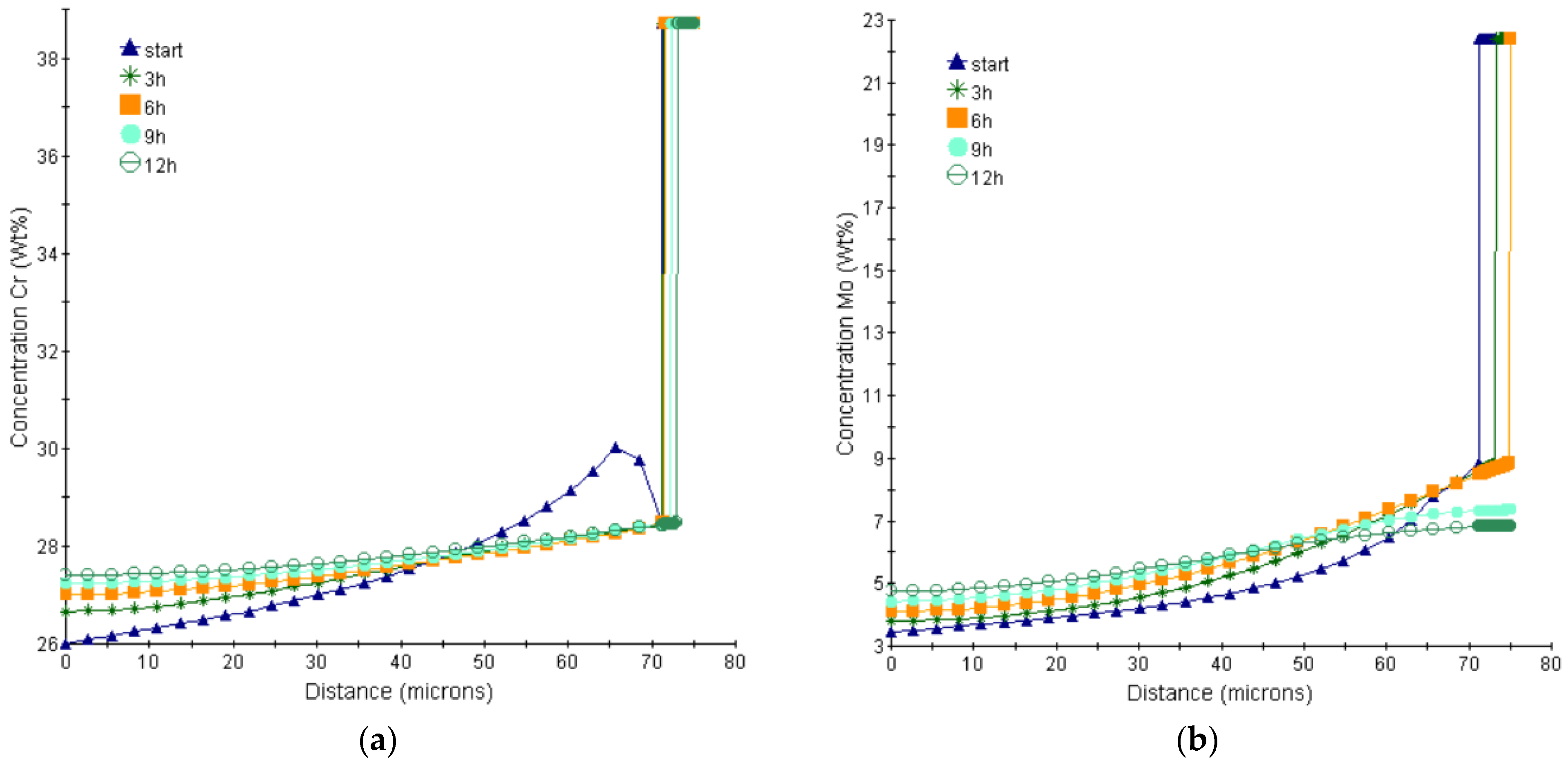
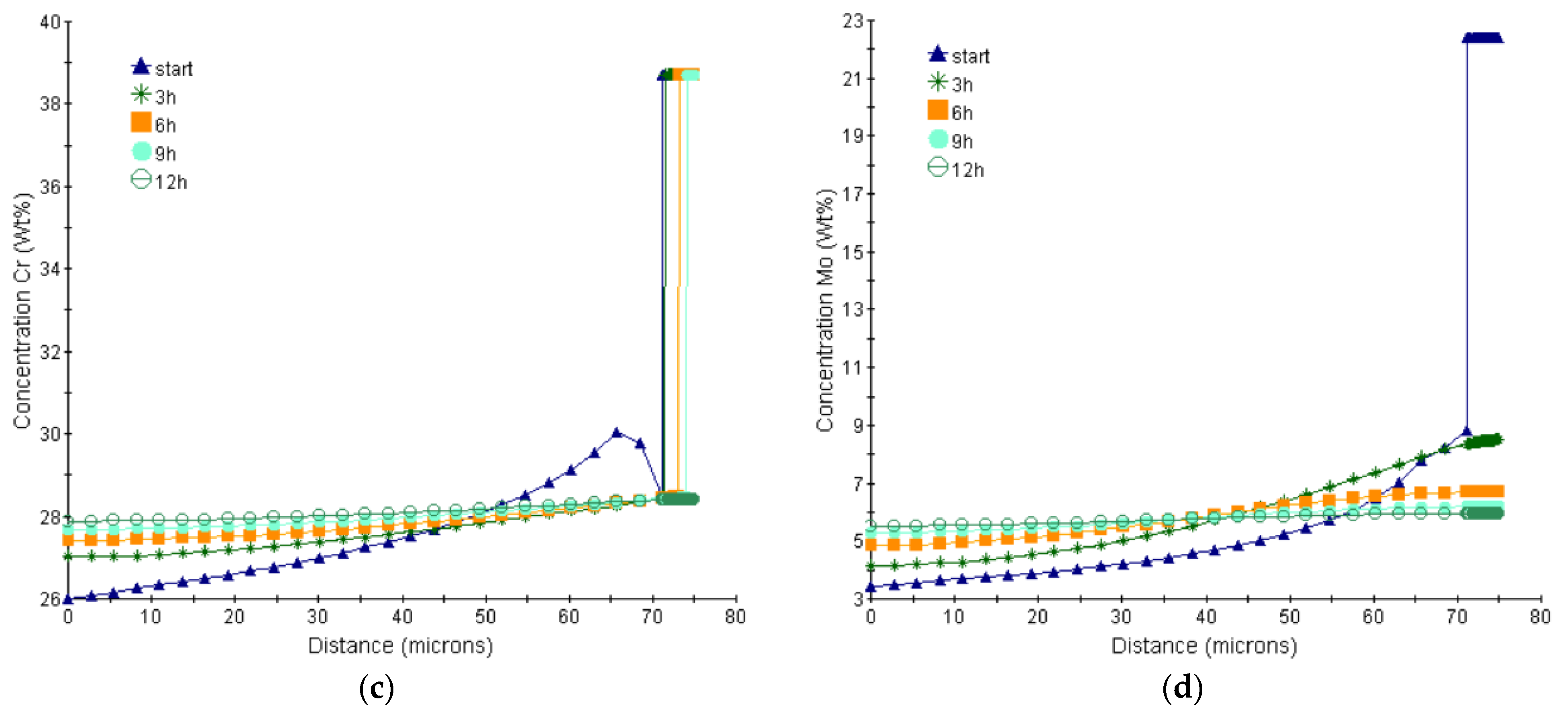
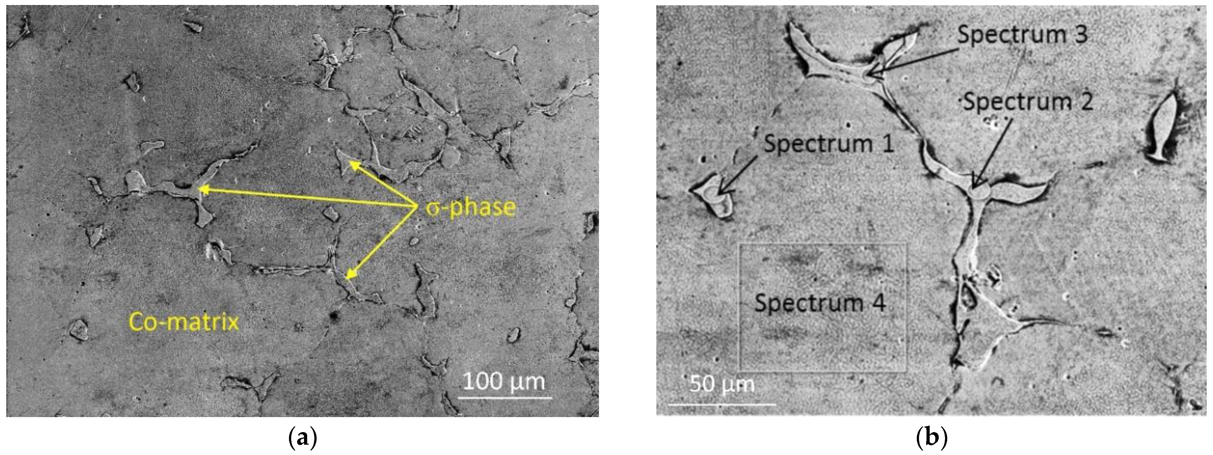
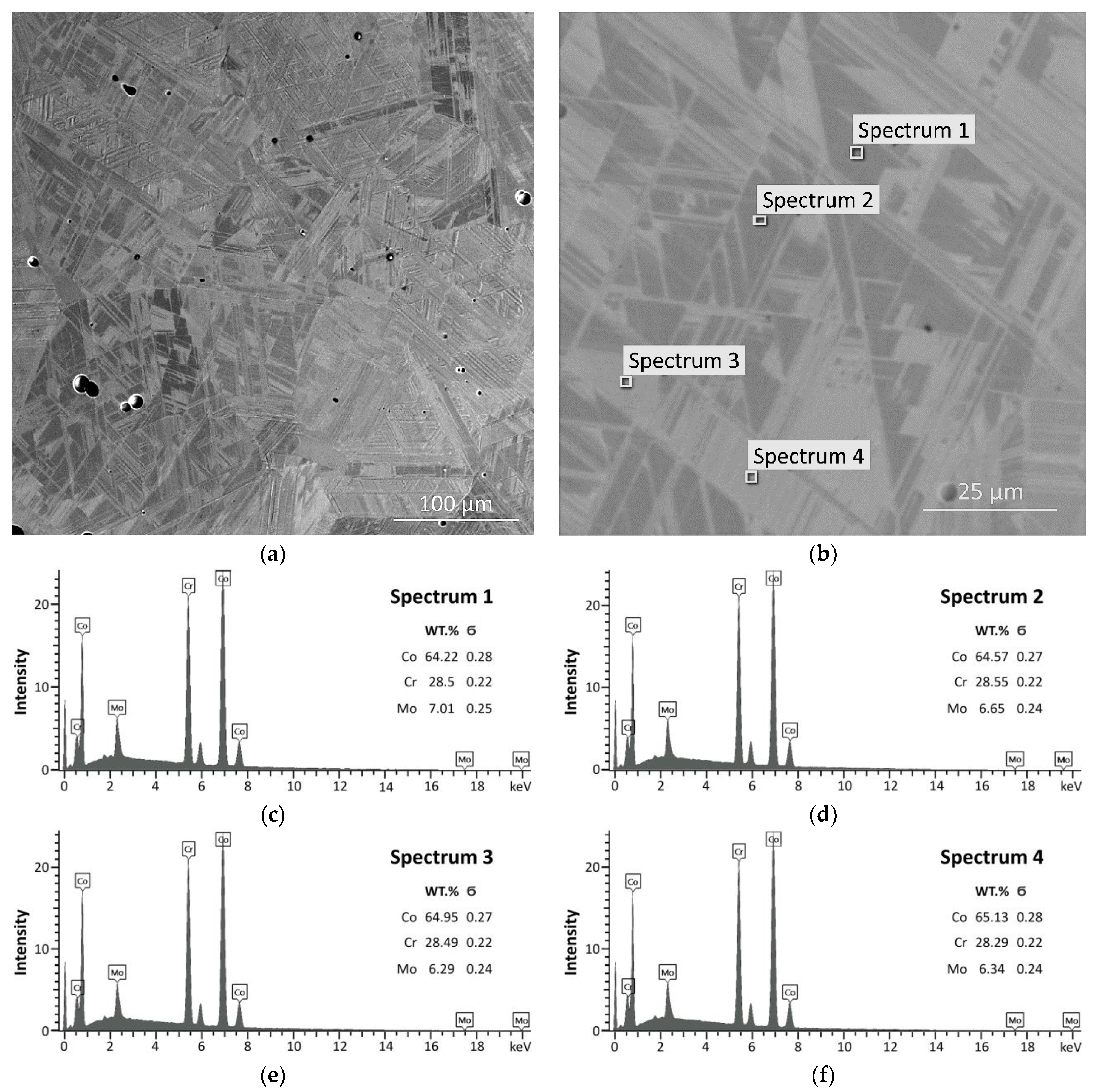
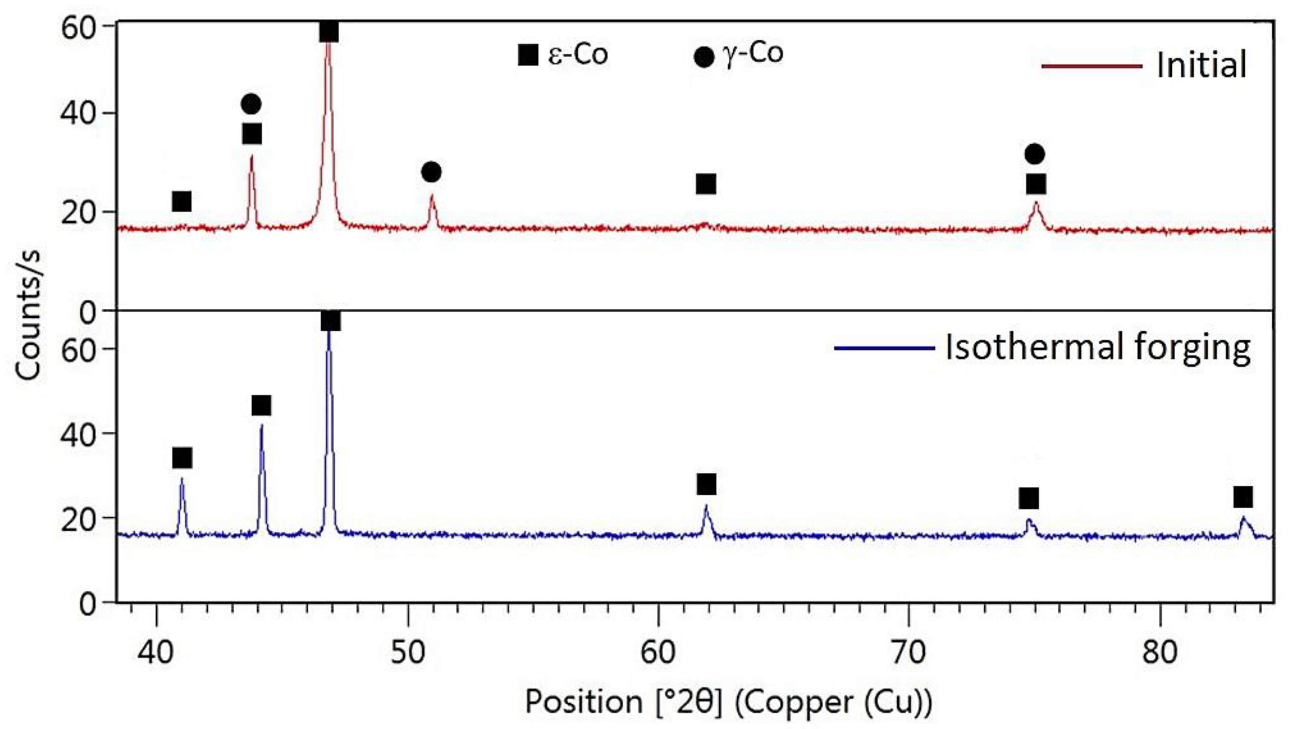
3.2. Microstructure and Phase Composition of Initial Workpiece

The microstructure (SEM) of the studied alloy in an as-cast state is shown in Figure 5a,b. The microstructure consisted of dendritic cells (~100–150 µm) based on a solid solution of Co matrix and phase precipitation along the boundaries of the dendritic cells. To identify the phase composition of the initial state of the alloy, the observed precipitation was investigated using electron microprobe analysis (EMPA). Spectrums 1–3 refer to the phase observed along the boundaries of dendritic cells; spectrum 4 is that of the matrix (Figure 5b).
In the as-cast state, the microstructure of the alloy was a cobalt-based solid solution matrix (Figure 5f). Intermetallic precipitates along the boundaries of dendritic cells had the composition of Co-Cr enriched in molybdenum (σ-phase) (Figure 5c–e).
The SEM microstructure of Co-Cr-Mo alloy after homogenization is shown in Figure 6a. The average size of observed grains was from 100 to 150 µm. The grain boundary precipitates of excess σ-phase were completely dissolved in the solid solution matrix. Numerous intersecting bands were observed in the grain structure, which, according to the data [3], corresponded to the mixed structure of the austenite (γ-Co) and martensite (ε-Co) phases. The spectrum regions 1–4 for EMPA and the phase composition of these spectrums are presented in Figure 6b,c–f, respectively. It can be seen that the elemental composition of spectrums 1–4 is approximately the same, which confirms the complete dissolution of the σ-phase in the alloy matrix.
Individual micropores were also observed in the central zone of the ingot. These micropores were ~5–10 µm in size and formed during the melting process.

3.3. Results of Computer Simulation

The temperature distribution of the workpiece at the end of the main steps of forging is shown in Figure 7a–e. Temperature control during the forging process of Co-Cr-Mo alloy is an important goal since it allows controlling the temperature range for deformation in the desired phase region and determines the microstructure and deformation force. The data obtained showed that the temperature did not decrease below 1000 °C at all deformation steps; this was ensured by heated dies. When radial forging to obtain a square cross-section (Figure 7a,c), two areas can be distinguished. The first one, which occupied 2/3 of the radius, had a higher temperature of about 1220–1160 °C. For the second one (near-surface), there was a sharper decrease in temperature from 1180–1160 °C closer to the center of the workpiece to 1080–1030 °C near the side surface. When upsetting the workpiece (Figure 7b,d), there was a slight increase in temperature due to the release of heat deformation.
According to JMatPro calculation and DTA results, it can be expected that the deformation process is likely to occur in the single-phase γ-region. However, during the forging, the precipitation of the σ-phase can occur, especially in the last steps of deformation at lower temperatures.
The temperature change in the tracking points on the side surface and in the center of the workpiece during the water quenching is shown in Figure 7f. As can be seen, the center and surface of the workpiece were cooled with a significant difference. In the center of the workpiece, the temperature decreased below 1000 °C only after 40 s, while the surface already had a temperature of about 500 °C. On the surface, there was a section of sharp cooling in the range from 450 °C to 130 °C, which occurred in 5–7 s. Then, the temperature changed quite smoothly, and the cooling rate decreased sharply. Thus, considering the significant differences in the cooling rates of the surface and center and polymorphic transformations of alloy, it can be expected that water quenching of a massive workpiece might lead to the formation of various types of structures over the workpiece cross-section.
The strain rate field makes it possible to estimate non-uniform deformation across the section. When forging ingots, it is important to ensure a sufficiently uniform processing of the microstructure over the entire cross-section. On the other hand, high strain rates can lead to reduced ductility and cracking during the forging process. According to processing maps [30], the most preferred deformation mode for the Co-28Cr-6Mo alloy was strain rates from 1 to 5 s−1. The strain rate field at the end of each main step of forging at simulation is shown in Figure 8. When radial forging to obtain a square cross-section, the cross-shaped distribution of the strain rate field was formed with a maximum value in the workpiece center from 0.2 to 0.3 s−1. Also, local high values up to 0.3 s−1 were observed on the surface at the corners of the workpiece. When upsetting the workpiece, the maximum values of strain rate were also observed in the central zone and were equal to 0.05–0.1 s−1.
Figure 9 shows the distribution of the triaxiality parameter at two points during deformation: at the side surface and in the center of the workpiece. During deformation, it is important to choose the values of deformation and temperature conditions that can ensure the production of quality products without defects. In Co-Cr-Mo alloys, which have a brittle σ-phase in their structure, this is critically important. The triaxiality parameter is used to evaluate the impact of the stress state. It is known that the higher the level of compressive stresses in the stress state scheme (i.e., the lower the value of the triaxiality parameter), the lower the likelihood of material failure under plastic deformation [34].
During radial forging to produce a square cross-section (refer to Figure 9a,c), the triaxiality parameter had a positive value at the surface and negative values in the center of the workpiece. When upsetting the workpiece (refer to Figure 9b,d), the triaxiality parameter had negative values both at the surface and in the center of the workpiece. At the last forging steps with profile rounding, values of the triaxiality parameter during the deformation process had differently directed changes. In the center, the triaxiality values decreased from 0.8 to −0.5 with the increase in deformation. At the side surface, on the contrary, the triaxiality values increased from −0.05 to 0.4. The final operation is the most dangerous in terms of failure probability due to the maximum accumulated strain and lowest temperature. When a brittle σ-phase is present in the alloy and high tensile stresses are applied, the risk of defects forming increases. Thus, it is preferable to carry out at least two intermediate short-term heating stages. This can also help equalize the temperature across the section and obtain a more uniform microstructure.

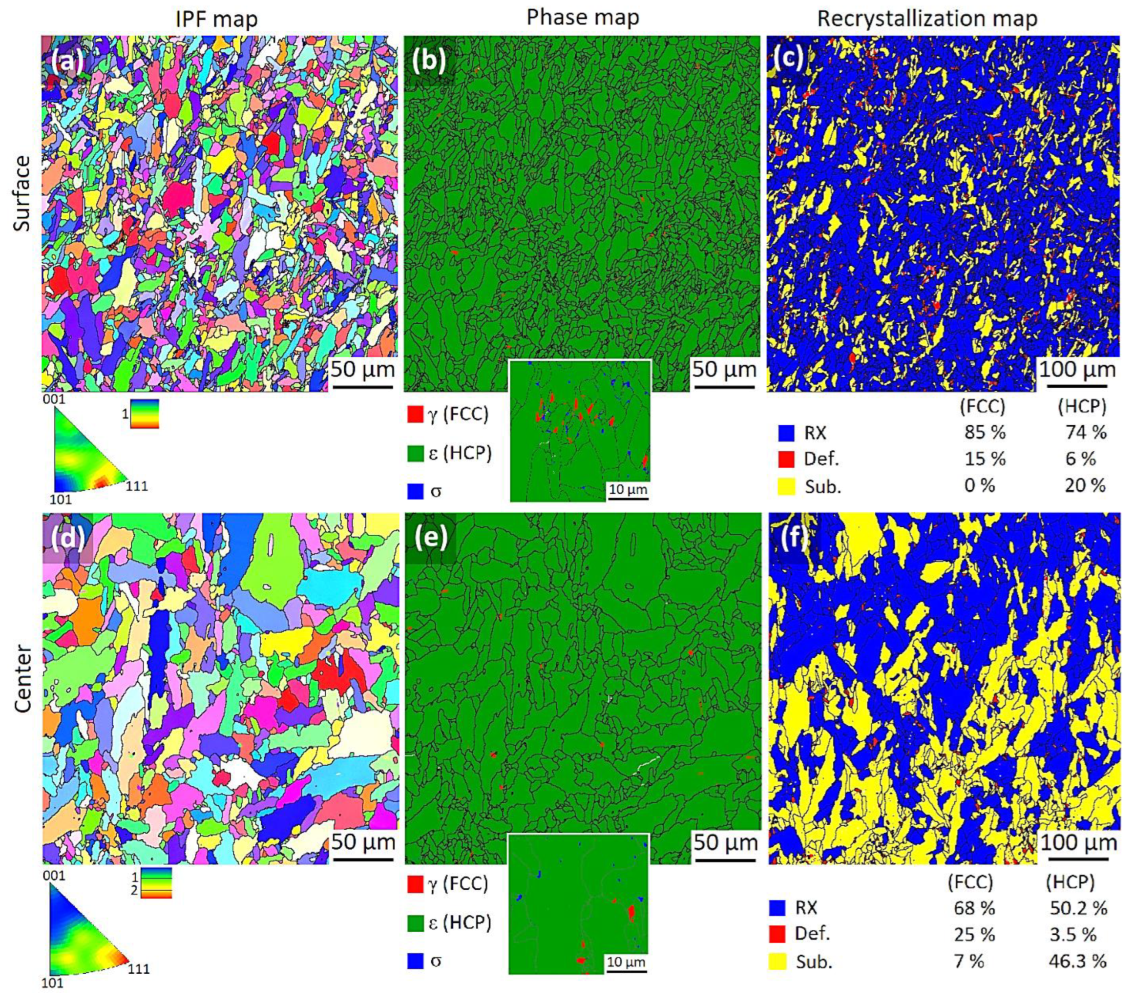
3.4. Microstructure and Phase Composition after Forging

The microstructure after forging and rapid water cooling is shown in Figure 10. Near the surface of the forging billet, ultra-fine dispersed (UFD) precipitates of the σ-phase (average size was 0.13 µm) located mainly along the boundaries of finer grains can be observed (Figure 10a,c,d). The center of the forging billet exhibited larger localized particles of the formed σ-phase, which were surrounded by finely dispersed precipitates that were clearly visible (Figure 10b). According to the JMatPro calculation, the start of the precipitation of the σ-phase was at a temperature of 1125 °C. With a further decrease in temperature, the volume fraction of the σ-phase can increase to ~20%, and after the polymorphic transformation, γ→ε decreases to 10% or less. Considering the obtained temperature fields (see Figure 7), the observed UFD particles of σ-phase can participate during deformation while cooling the forging billet below temperatures of 1125 °C and during rapid cooling after deformation. Larger particles in the center (Figure 10b) were likely formed due to the slower cooling rate compared to the surface. The precipitation of UFD particles of phase was observed in the zones of small equiaxed recrystallized grains (Figure 10c), which was consistent with the results of Chiba et al. [35], obtained for upsetting samples of the Co–28Cr–6Mo–0.16N alloy.
Figure 11 shows the XRD results for the initial specimen after homogenization and for the specimen after isothermal forging. In the initial state, the phase composition of the alloy consists of a mixture of (ε-Co) and (γ-Co) phases, which also confirms the type of structure in Figure 6. After isothermal forging, the material consists almost exclusively of the (ε-Co) phase. It is also to be noted that the profiles show no diffraction peaks corresponding to the σ-phase or other precipitates, indicating that the amount of these precipitates is small, commensurate with the sensitivity limit of the equipment. Thus, isothermal forging followed by rapid cooling leads to a change in the initial phase composition and the formation of a single-phase martensitic structure with minor σ-phase precipitates.
The EBSD microstructure (IPF map) of the alloy after forging for the surface and the center zones is shown in Figure 12a,d. After isothermal forging, a mixed grain microstructure was formed consisting of large grains up to 25 µm in size elongated along the deformation direction and zones of more equiaxed small grains (Figure 13a). The average size of the grain at the surface was 5.3 µm. In the center, larger and equiaxed grains up to 60 µm and an average size of 9.4 µm were formed (Figure 13b).
The phase maps for the surface and the center zones are shown in Figure 12b,e. As can be observed, after forging and water quenching, a stable phase of athermal ε-martensite (hcp) was formed over the entire cross-section of the forging billet during rapid cooling from the single-phase γ-region (fcc). At high magnification, the residual austenitic γ-phase and ultra-fine dispersed σ-phase particles can be seen in some areas, but their proportion was small and did not exceed 1.5% in total.
The recrystallization maps of Co-Cr-Mo alloy are shown in Figure 12c,f. Near the surface of the forged billet for the predominant type of structure (HCP), a large volume was occupied by recrystallized grains (~74%) and about 20% by polygonized grains (Figure 12c). After quenching, there was approximately 6% of the deformed microstructure in the material. The mixture of recrystallized and polygonized grains (approximately 50.2 and 46.3%, respectively) was dominated in the center of the forging billet, with residual deformed fine grains accounting for 3.5% (Figure 12f). It is also interesting to note that for the residual austenitic FCC phase, the proportion of the polygonized structure was significantly reduced while the proportion of the deformed structure increased. The residual amount of the deformed structure indicated that during forging at higher temperatures, dynamic recrystallization processes can occur with the formation of new grain nuclei and their growth during intermediate heating, and at lower temperatures (at the last step of forging), the formation of a partially deformed microstructure is possible. After the end of the deformation, the process of static recrystallization began, resulting in the volume of deformed grains decreasing (and was retained mainly for the γ-phase during rapid cooling).
Thus, isothermal forging in the temperature range of 1100–1200 °C and at low strain rates up to 1 s−1 led to dynamic recrystallization and dynamic polygonization during deformation, which was consistent with the experimental flow curves (see Figure 2). Larger grains indicate subsequent metadynamic and partially static recrystallization. These modes of isothermal forging contributed to obtaining a structure without visible pores, cracks, and large inclusions and made it possible to use the forging billet for further deformation by different metal forming methods.

4. Conclusions

In this article, the analysis of temperature–deformation conditions during isothermal forging and subsequent water quenching, microstructure evolution, and phase composition of the biomedical alloy Co-28Cr-6Mo was carried out. Based on the data obtained, the following conclusions can be made:
  • Based on thermodynamic calculations (JMatPro) and DTA analysis, the main characteristic temperatures and temperature-time ranges of homogenization were determined. The phase transformation γ→ε occurred in the temperature range of 960–980 °C. To completely dissolve the σ-phase and eliminate dendritic segregation of the main alloying elements, it is necessary to homogenize the alloy at a temperature of 1230–1250 °C for at least 9 h before deformation.
  • According to the results of the FEM simulation, the forging occurred in a single-phase γ-region. The forging temperature did not decrease below 1000 °C. However, to reduce the probability of σ-phase precipitation and crack formation during deformation and to decrease forging forces, at least two intermediate heating stages should be performed.
  • During forging and subsequent rapid cooling, ultra-fine dispersed particles of the σ-phase (0.13 ± 0.01 µm) were precipitated along the boundaries of recrystallized fine grains. Larger particles in the center of the workpiece were formed due to the slower cooling rate compared to the surface.
  • After isothermal forging, a mixed grain microstructure was formed consisting of large grains elongated along the deformation direction and zones of more equiaxed small grains. The average size of grain was in the range of 5–10 µm. During rapid cooling from the single-phase γ-region (fcc), a stable phase of athermal ε-martensite (hcp) was formed over the entire cross-section of the forging billet.
  • Isothermal forging in the temperature range of 1100–1200 °C and at low strain rates up to 1 s−1 leads to dynamic recrystallization and polygonization during deformation and contributes to obtaining a structure without visible pores, cracks, and large inclusions. Thus, it makes it possible to use the forging billet for further deformation by different metal forming methods.

Author Contributions

Conceptualization, Y.V.G., A.V.S. and T.Y.K.; data curation, V.V.C. and A.M.A.A.; formal analysis, A.M.A.A. and M.M.K.; investigation, T.Y.K., A.V.S., M.M.K. and V.V.C.; methodology, Y.V.G. and S.P.G.; supervision, S.P.G.; validation, A.V.S. and M.M.K.; visualization, A.M.A.A.; writing—original draft, Y.V.G., A.V.S., T.Y.K. and M.M.K.; writing—review and editing, Y.V.G. and S.P.G. All authors have read and agreed to the published version of the manuscript.

Funding

This research was funded by the Russian Science Foundation, grant number 23-19-00477, https://rscf.ru/project/23-19-00477/ (accessed on 15 August 2023).

Data Availability Statement

The datasets generated during and/or analyzed during the current study are available from the corresponding author upon reasonable request.

Conflicts of Interest

The authors declare no conflict of interest.

References

  1. Tanzi, M.C.; Farè, S.; Candiani, G. Chapter 4—Biomaterials and Applications. In Foundations of Biomaterials Engineering; Tanzi, M.C., Farè, S., Candiani, G., Eds.; Academic Press: Cambridge, MA, USA, 2019; pp. 199–287. [Google Scholar] [CrossRef]
  2. Ibrahim, M.Z.; Sarhan, A.A.D.; Yusuf, F.; Hamdi, M. Biomedical materials and techniques to improve the tribological, mechanical and biomedical properties of orthopedic implants—A review article. J. Alloys Compd. 2017, 714, 636–667. [Google Scholar] [CrossRef]
  3. Sedlaček, M.; Zupančič, K.; Šetina Batič, B.; Kosec, B.; Zorc, M.; Nagode, A. Influence of Precipitation Hardening on the Mechanical Properties of Co-Cr-Mo and Co-Cr-W-Mo Dental Alloys. Metals 2023, 13, 637. [Google Scholar] [CrossRef]
  4. Silva, R.; Santos, M.D.d.; Madureira, R.; Soares, R.; Neto, R.; Vieira, Â.A.; Gonçalves, P.A.R.; Leite, P.M.S.M.; Vieira, L.; Viana, F. Scratch and Wear Behaviour of Co-Cr-Mo Alloy in Ringer’s Lactate Solution. Materials 2023, 16, 2923. [Google Scholar] [CrossRef] [PubMed]
  5. Namus, R.; Rainforth, W.M.; Huang, Y.; Langdon, T.G. Effect of grain size and crystallographic structure on the corrosion andtribocorrosion behaviour of a CoCrMo biomedical grade alloy in simulated body fluid. Wear 2021, 478–479, 203884. [Google Scholar] [CrossRef]
  6. Basha, M.; Moustafa, E.B.; Ibrahim, K.M.; Basha, M.A.; Mosleh, A.O. The Effect of Si Addition on the Microstructure, Mechanical Properties, and Wear Rate of the Co–Cr–Mo-Based Biomedical Alloys. Silicon 2023, 1–7. [Google Scholar] [CrossRef]
  7. Cremer, L.; Nortje, B.D.; van der Merwe, J.; Becker, T.H. Wear of Conventional UHMWPE Articulating Against Additively Manufactured Ti-6Al-4V and Co-Cr-Mo. Biotribology 2023, 33–34, 100231. [Google Scholar] [CrossRef]
  8. Chen, Q.; Thouas, G.A. Metallic implant biomaterials. Mater. Sci. Eng. R 2015, 87, 1–57. [Google Scholar] [CrossRef]
  9. Yamanaka, K.; Mori, M.; Chiba, A. Effects of nitrogen addition on microstructure and mechanical behavior of biomedical Co–Cr–Mo alloys. J. Mech. Behav. Biomed. Mater. 2014, 29, 417–426. [Google Scholar] [CrossRef]
  10. Jabali, F.Z.H.; Ketabchi, M.; Bruschi, S.; Ghiotti, A. Effects of carbide precipitation on the microstructural and tribological properties of Co–Cr–Mo–C medical implants after thermal treatment. J. Mater. Sci. 2016, 51, 4495–4508. [Google Scholar] [CrossRef]
  11. Chiba, A.; Kumagai, M.; Nomura, N.; Miyakawa, S. Pin-on-disk wear behavior in a like-on-like configuration in a biological environment of high carbon cast and low carbon forged Co–29Cr–6Mo alloys. Acta Mater. 2007, 55, 1309–1318. [Google Scholar] [CrossRef]
  12. Im, H.-T.; Kim, D.H.; Kim, Y.D.; Fadonougbo, J.O.; Mo, C.B.; Park, J.-Y.; Park, K.B.; Kang, J.-W.; Kang, H.-S.; Park, H.-K. Effect of phase transformation on the mechanical properties of the Co-Cr-Mo alloy fabricated by selective laser melting. Mater. Charact. 2022, 186, 111767. [Google Scholar] [CrossRef]
  13. Rosenthal, R.; Cardoso, B.R.; Bott, I.S.; Paranhos, R.P.R.; Carvalho, E.A. Phase characterization in as-cast F-75 Co–Cr–Mo–C alloy. J. Mater. Sci. 2010, 45, 4021–4028. [Google Scholar] [CrossRef]
  14. Giacchi, J.V.; Fornaro, O.; Palacio, H. Microstructural evolution during solution treatment of Co–Cr–Mo–C biocompatible alloys. Mater. Charact. 2012, 68, 49–57. [Google Scholar] [CrossRef]
  15. Biezma, M.V.; Martin, U.; Linhardt, P.; Ress, J.; Rodríguez, C.; Bastidas, D.M. Non-destructive techniques for the detection of sigma phase in duplex stainless steel: A comprehensive review. Eng. Fail. Anal. 2021, 122, 105227. [Google Scholar] [CrossRef]
  16. Wang, R. Precipitation of sigma phase in duplex stainless steel and recent development on its detection by electrochemical potentiokinetic reactivation:A review. Corros. Comm. 2021, 2, 41–54. [Google Scholar] [CrossRef]
  17. Mori, M.; Guo, T.; Yamanaka, K.; Wang, Z.; Yoshida, K.; Onuki, Y.; Sato, S.; Chiba, A.; Misra, R.D.K. The significance of thermomechanical processing on the cellular response of biomedical Co–Cr–Mo alloys. J. Mech. Behav. Biomed. Mater. 2022, 133, 105360. [Google Scholar] [CrossRef]
  18. Yamanaka, K.; Mori, M.; Koizumi, Y.; Chiba, A. Local strain evolution due to athermal γ→ε martensitic transformation in biomedical Co-Cr-Mo alloys. J. Mech. Behav. Biomed. Mater. 2014, 32, 52–61. [Google Scholar] [CrossRef]
  19. Huang, P.; López, H. Strain induced ε-martensite in a Co–Cr–Mo alloy: Grain size effects. Mater. Lett. 1999, 39, 244–248. [Google Scholar] [CrossRef]
  20. Bandyopadhyay, A.; Traxel, K.D.; Avila, J.D.; Mitra, I.; Bose, S. CoCr Alloys. In Biomaterials Science; Elsevier: Amsterdam, The Netherlands, 2020; pp. 257–269. [Google Scholar] [CrossRef]
  21. Chiba, A.; Kumagai, K.; Takeda, H.; Nomura, N. Mechanical properties of forged low Ni and C-containing Co-Cr-Mo biomedical implant alloy. Mater. Sci. Forum 2005, 475–479, 2317–2322. [Google Scholar] [CrossRef]
  22. Ponomarenko, D.A.; Letnikov, M.N.; Skugorev, A.V.; Sidorov, S.A. Forging of gas turbine discs from nickel-based superalloys in isothermal conditions with the use of specialized hydraulic presses. Forg. Stamp. Manuf. Met. Form. 2018, 3, 19–25. Available online: https://elibrary.ru/item.asp?id=32810471 (accessed on 5 September 2023). (In Russian).
  23. Ponomarenko, D.A.; Skugorev, A.V.; Sidorov, S.A.; Strokov, V.V. Technological capabilities of specialized isothermal presses with maximum force 6,5 and 16 MN in the manufacture of parts for aviation and space purposes. Forg. Stamp. Manuf. Met. Form. 2015, 9, 36–41. Available online: https://elibrary.ru/item.asp?id=24342081 (accessed on 5 September 2023). (In Russian).
  24. Immarigeon, J.; Rajan, K.; Wallace, W. Microstructural Changes during Isothermal Forging of a Co-Cr-Mo Alloy. Metall. Trans. A 1984, 15, 339–345. [Google Scholar] [CrossRef]
  25. Yamanaka, K.; Mori, M.; Chiba, A. Mechanical properties of as-forged Ni-free Co–29Cr–6Mo alloys with ultrafine-grained microstructure. Mater. Sci. Eng. A 2011, 528, 5961–5966. [Google Scholar] [CrossRef]
  26. Yamanaka, K.; Mori, M.; Chiba, A. Enhanced Mechanical Properties of As-Forged Co-Cr-Mo-N Alloys with Ultrafine-Grained Structures. Met. Mater. Trans. A 2012, 43, 5243–5257. [Google Scholar] [CrossRef]
  27. Yamanaka, K.; Mori, M.; Yoshida, K.; Balvay, S.; Hartmann, D.; Fabrègue, D.; Chiba, A. Preparation of high-strength Co−Cr−Mo alloy rods via hot-caliber rolling. Materialia 2020, 12, 100729. [Google Scholar] [CrossRef]
  28. Li, Y.; Koizumi, Y.; Chiba, A. Dynamic recrystallization behavior of biomedical Co-29Cr-6Mo-0.16N alloy with extremely low stacking fault energy. Mater. Sci. Eng. A 2016, 668, 86–96. [Google Scholar] [CrossRef]
  29. Yang, S.; Umbrello, D.; Dillon, O.W.; Jawahir, I.S. Numerical Investigation of Dynamic Recrystallization Induced Microstructural Evolution in Cryogenic Burnishing of Co-Cr-Mo Biomaterial. J. Mater. Eng. Perform. 2022, 31, 6904–6921. [Google Scholar] [CrossRef]
  30. Gamin, Y.V.; Korotitskiy, A.V.; Kin, T.Y.; Galkin, S.P.; Kostin, S.A.; Tikhomirov, E.O. Development of Temperature-Rate Modes of Hot Deformation of the Co–28Cr–6Mo Alloy Based on Processing Maps. Steel Transl. 2022, 52, 1027–1036. [Google Scholar] [CrossRef]
  31. BS ISO 5832-12:2007; Implants for Surgery—Metallic Materials—Part 12: Wrought Cobalt Chromium-Molybedenium Alloy. ISO: Geneva, Switzerland, 2007.
  32. QForm, Version 9.0.10; Windows; Micas Simulations Limited: Oxford, UK, 2020.
  33. Saunders, N.; Guo, U.K.Z.; Li, X.; Miodownik, A.P.; Schillé, J.P. Using JMatPro to model materials properties and behavior. JOM 2003, 55, 60–65. [Google Scholar] [CrossRef]
  34. Kolmogorov, V.A. Stress, Deformation, Destruction; Metallurgy: Moscow, Russia, 1970. (In Russian) [Google Scholar]
  35. Chiba, A.; Lee, S.H.; Matsumoto, H.; Nakamurac, M. Construction of processing map for biomedical Co–28Cr–6Mo–0.16N alloy by studying its hot deformation behavior using compression tests. Mater. Sci. Eng. A 2009, 513, 286–293. [Google Scholar] [CrossRef]
Figure 1. Scheme of main operations of isothermal forging (a) and forged billet before water quenching (b).
Metals 13 01583 g001
Figure 2. Stress–strain curves of Co-28Cr-6Mo alloy for different temperatures: (a) 1000 °C; (b) 1100 °C; and (c) 1200 °C.
Metals 13 01583 g002
Figure 3. Equilibrium phase diagram of Co-28Cr-6Mo calculated by JMatPro software (a) and DTA curve of Co-28Cr-6Mo (b).
Metals 13 01583 g003
Figure 4. Change in concentration of alloying elements over dendritic cell section depending on temperature and time of homogenization: (a,b) 1200 °C; (c,d) 1250 °C.
Metals 13 01583 g004aMetals 13 01583 g004b
Figure 5. SEM microstructure of alloy in as-cast state (a,b) and spectrums 1–4 (cf).
Metals 13 01583 g005aMetals 13 01583 g005b
Figure 6. SEM microstructure of ingot center after homogenization (a,b) and spectrums 1–4 (cf).
Metals 13 01583 g006
Figure 7. Workpiece temperature distribution during forging (ae) and temperature curves during water quenching (f).
Metals 13 01583 g007
Figure 8. Distribution of strain rate fields at main steps of forging. 1. Radial forging to obtain a 65 × 65 mm square cross-section; 2. Upsetting with a deformation degree of ~30%; 3. Radial forging to obtain a 60 × 60 mm square cross-section; 4. Upsetting with a deformation degree of ~30%; 5. Radial forging to obtain a round 55 mm cross-section).
Metals 13 01583 g008
Figure 9. Triaxiality: (a) radial forging to obtain a 65 mm × 65 mm square cross-section; (b) upsetting; (c) radial forging to obtain a 60 mm × 60 mm square cross-section; (d) upsetting; and (e) radial forging to obtain a 55 mm round cross-section.
Metals 13 01583 g009
Figure 10. SEM microstructure of Co-Cr-Mo alloy after forging: (a,c) surface and (b,d) average size distribution of σ-phase particles.
Metals 13 01583 g010aMetals 13 01583 g010b
Figure 11. XRD patterns of the Co-28Cr-6Mo alloy after homogenization and after isothermal forging.
Metals 13 01583 g011
Figure 12. EBSD maps of sample after forging: (a,d) IPF map; (b,e) phase map; and (c,f) recrystallization map (RX—recrystallized; Def.—deformed; and Sub.—substructured).
Metals 13 01583 g012
Figure 13. Distribution of average size in forging billet: (a) surface; (b) center.
Metals 13 01583 g013
Table 1. Chemical composition of ingots from Co-Cr-Mo alloy.
Chemical Element wt, %
CoCrMoFeMnSiCNiN
Ingot Matrix28.15.80.020.30.20.017<0.050.0006
ISO 5832-12:2007Matrix26.0–30.05.0–7.0<0.75<1.0<1.0<0.140<1.00<0.25
Table 2. Simulation parameters of isothermal forging.
ParameterUnit of
Measurement
Value
Heating temperature of workpiece°C1200
Tool temperature°C950
Environment temperature°C20
Water temperature for quenching°C20
Friction factor between workpiece and tool (flat dies) 0.4
Material of tool (flat dies) Ni-based alloy
Traverse speed of upper flat diemm/s8
Transportation time from furnace to presss8
Time of water quenchings360
Table 3. Characteristic temperatures of Co-Cr-Mo alloy.
Critical Temperature Point JMatPro CalculationDTA Curve Δ/%
Liquidus1410 °C1428 °C1.26
Solidus1393 °C1392 */1413 ** °C0.07/1.42
Polymorphic transformation γ→ε921 °C962–980 °C4.26/6.02
* at the heating. ** at the cooling.
Disclaimer/Publisher’s Note: The statements, opinions and data contained in all publications are solely those of the individual author(s) and contributor(s) and not of MDPI and/or the editor(s). MDPI and/or the editor(s) disclaim responsibility for any injury to people or property resulting from any ideas, methods, instructions or products referred to in the content.

