Localized Perturbation Load Approach for Buckling Design of Thin-Walled Steel Cylindrical Shells under Partial Axial Compression

Abstract
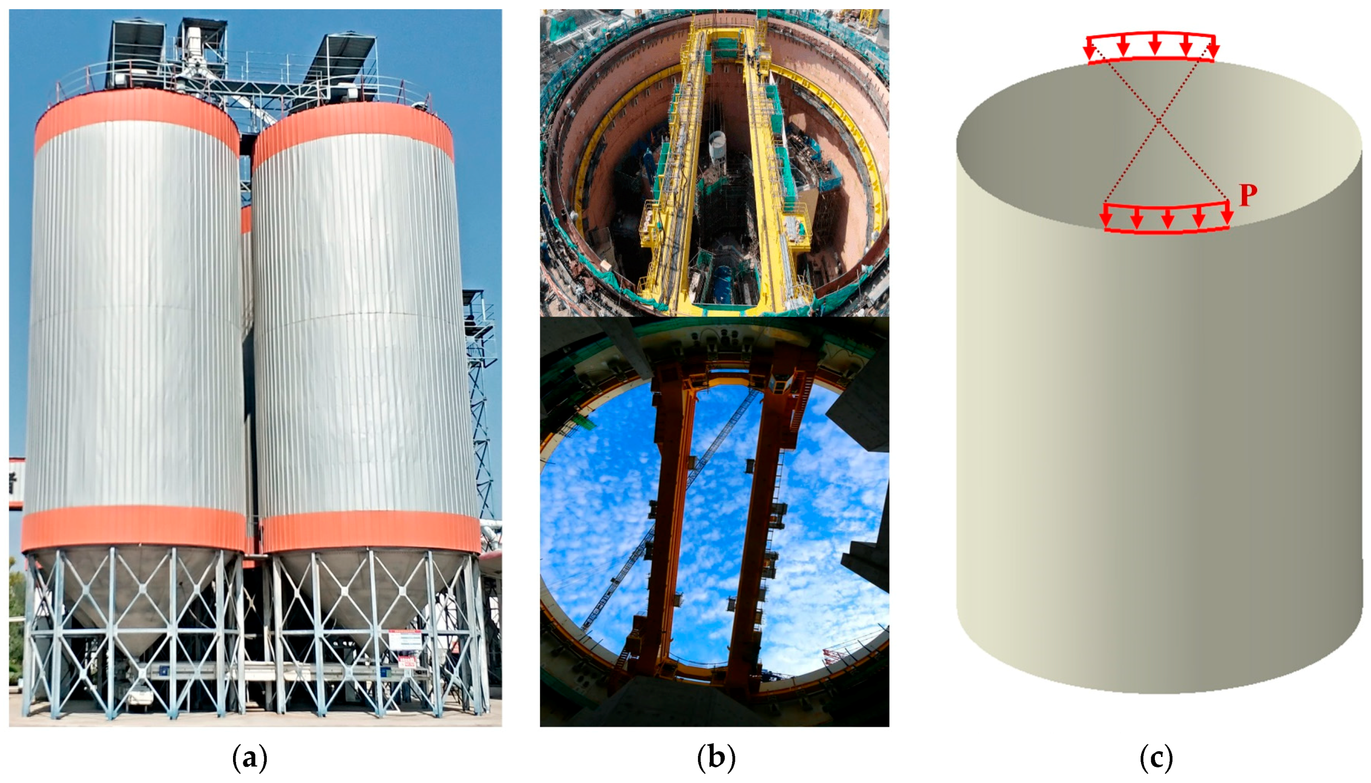
:1. Introduction
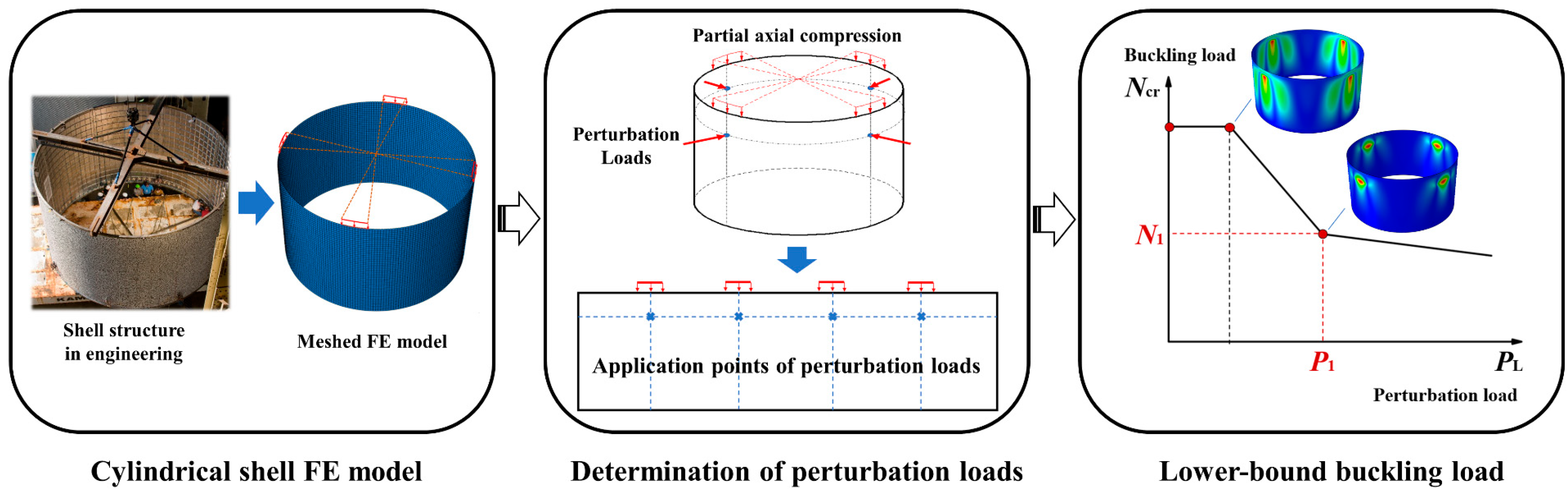
2. Localized Perturbation Load Approach (LPLA)
- Establishment of the cylindrical shell FE model with partial axial compression loading condition.
- Determination of the location and number of perturbation loads according to the distribution of partial axial compression loads.
- Calculation of the lower-bound buckling load as the design load of the cylindrical shell.
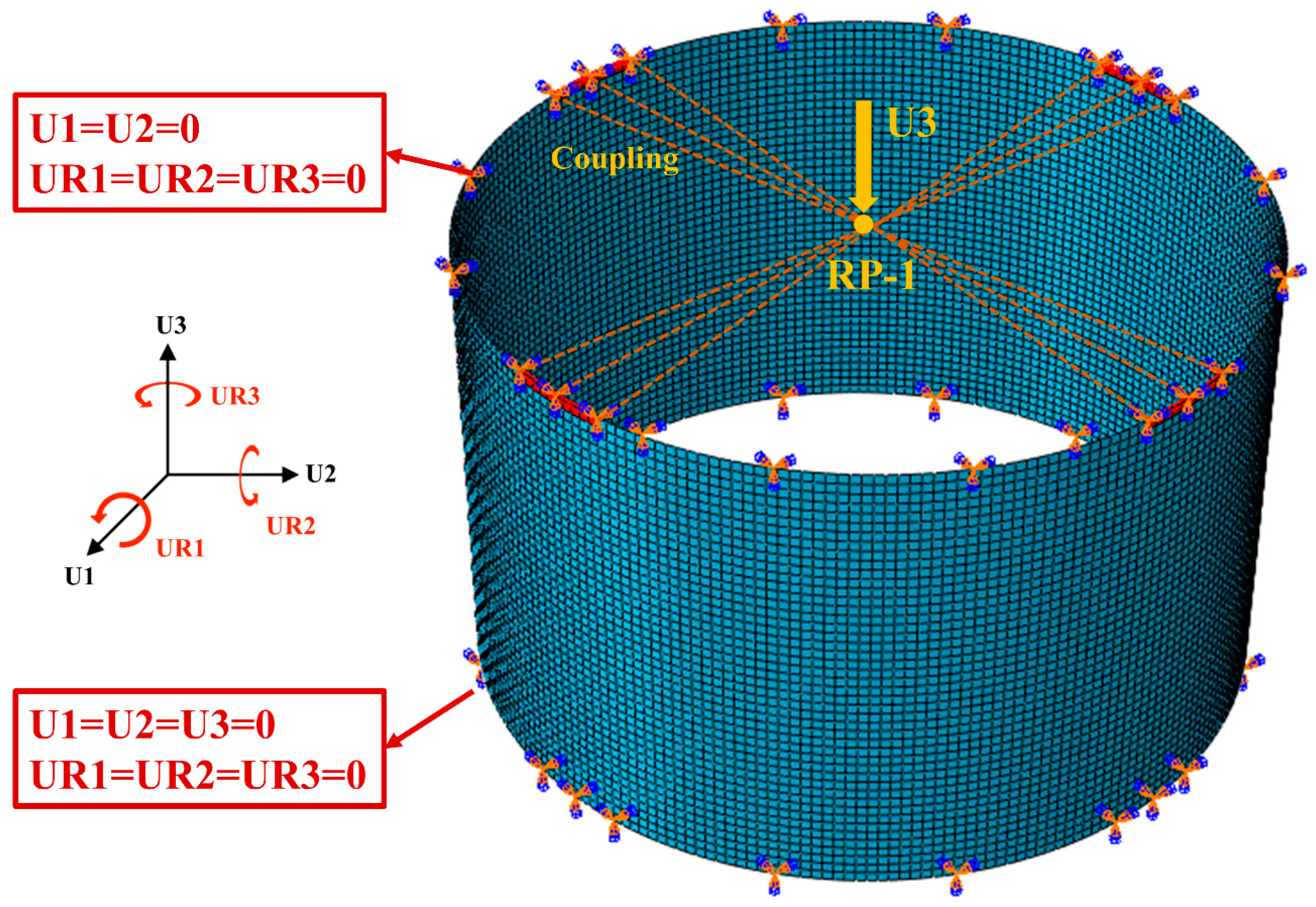
2.1. FE Modeling
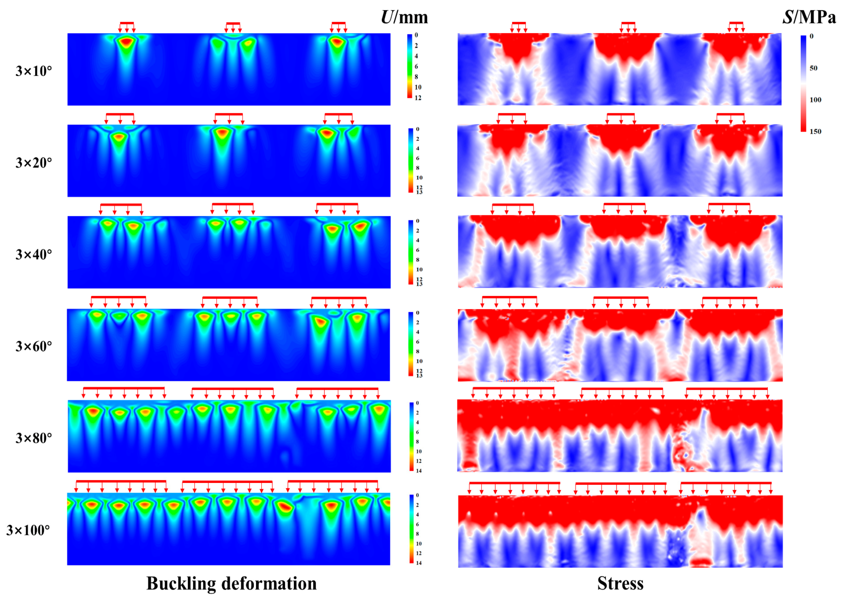
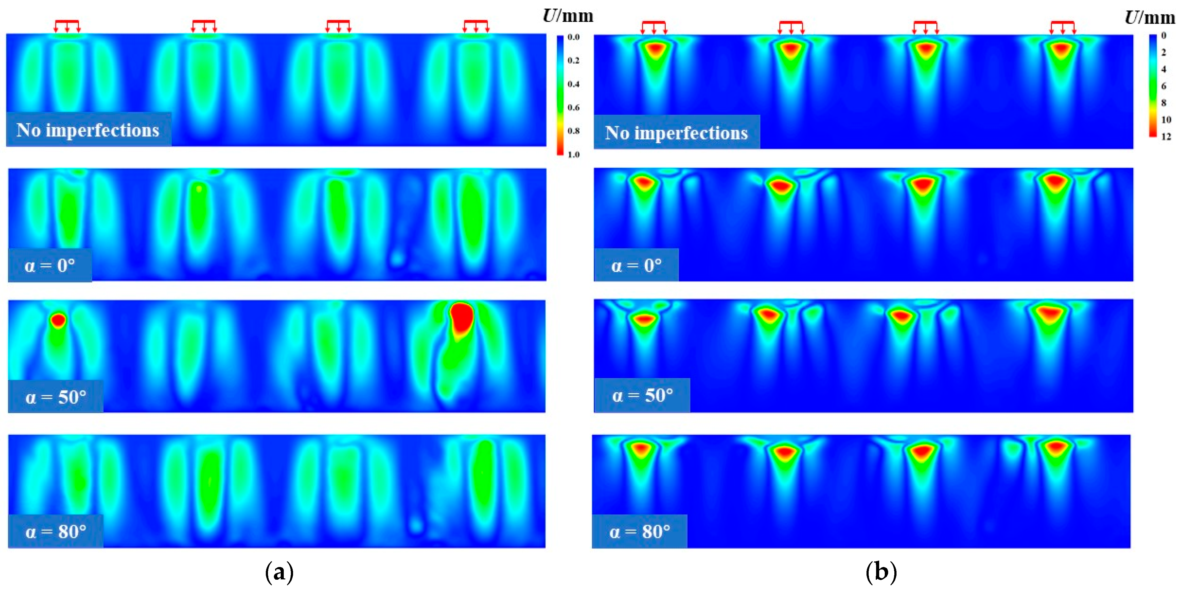
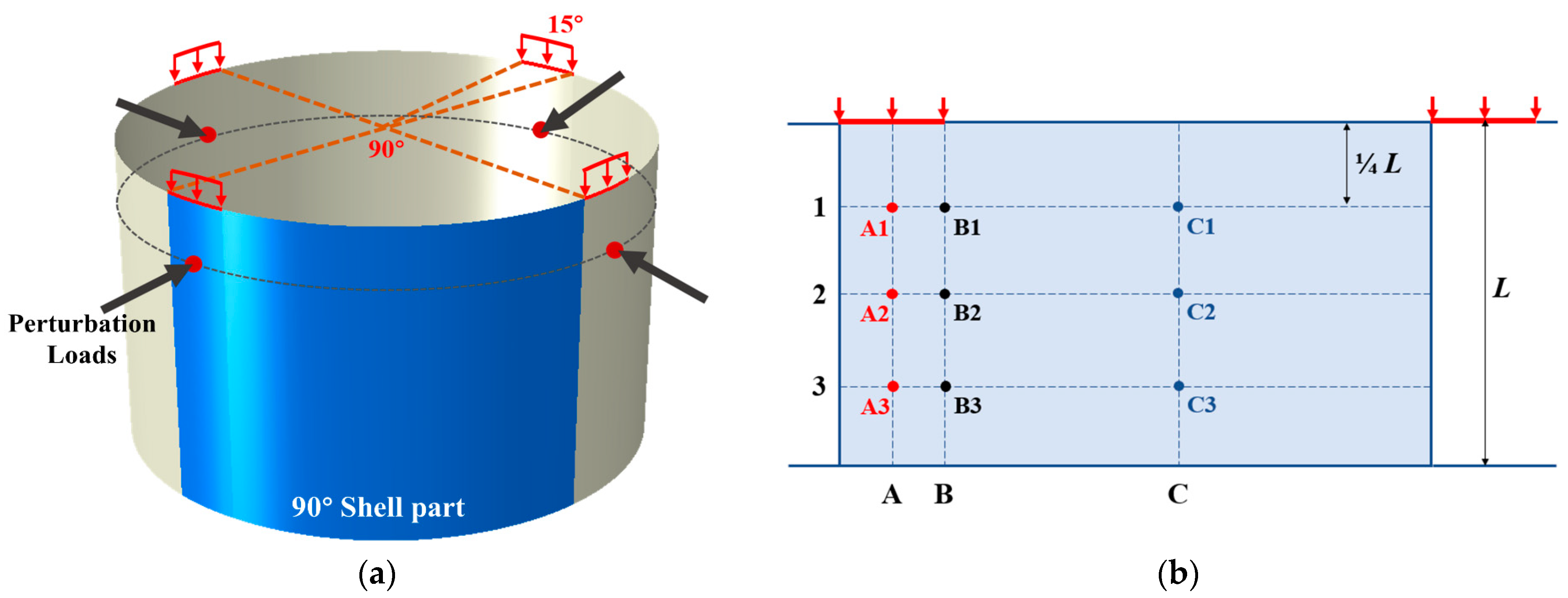
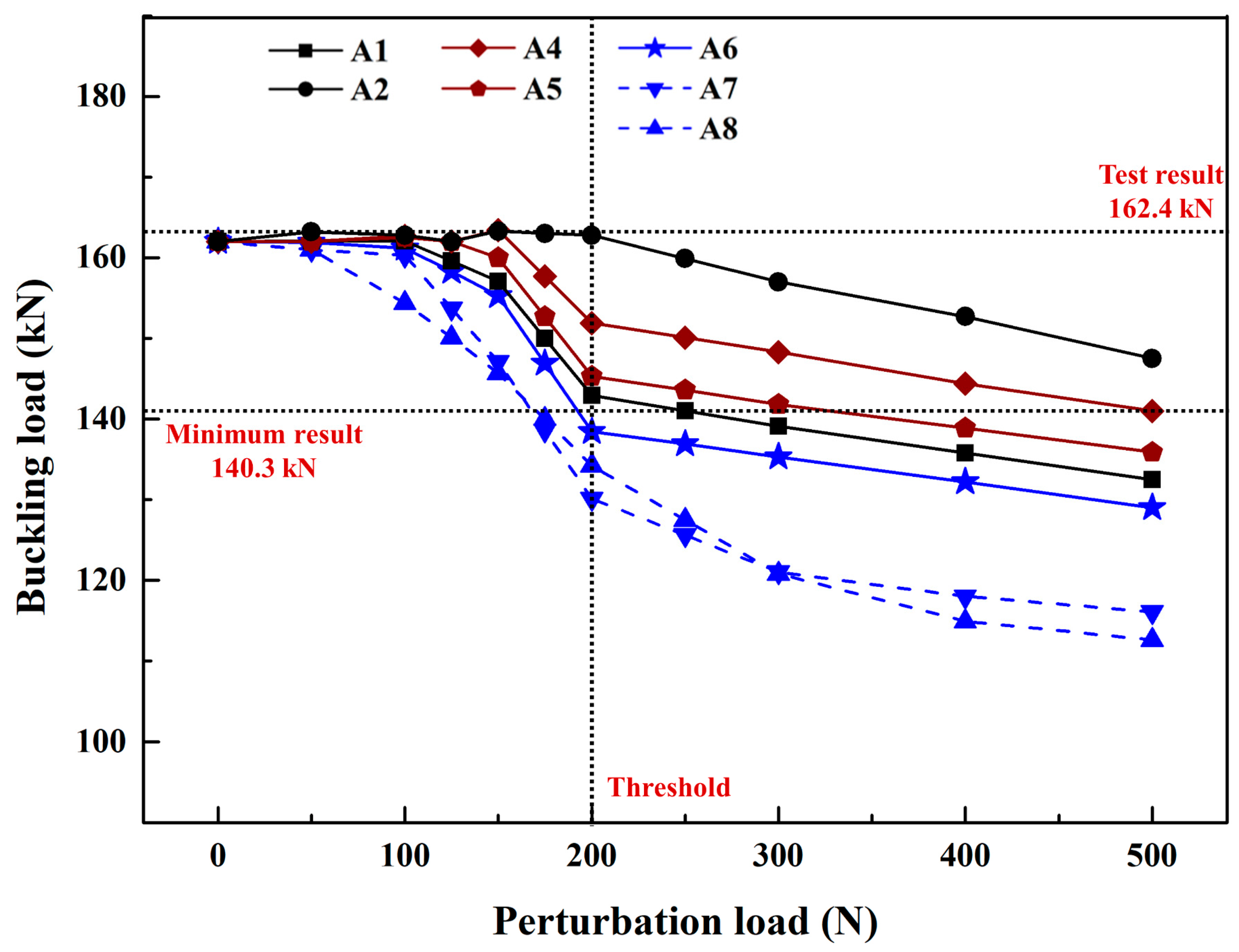
2.2. Determination of the Locations of Perturbation Loads
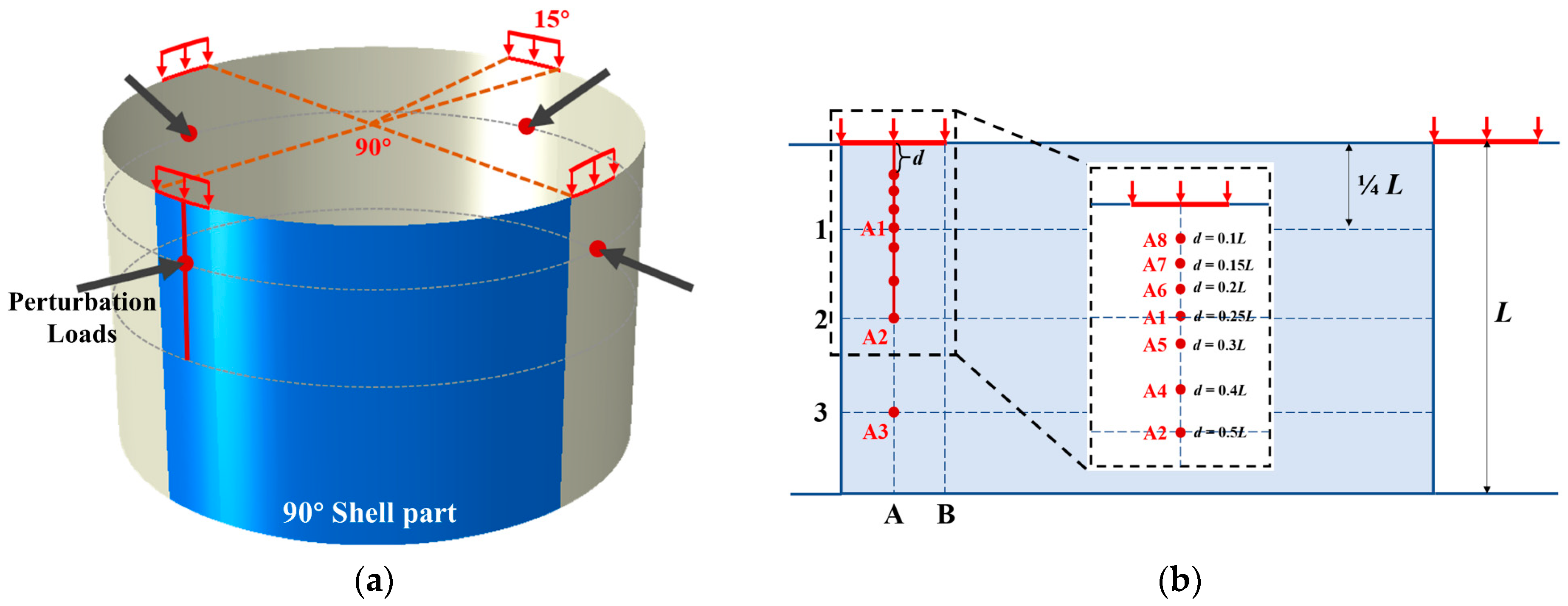
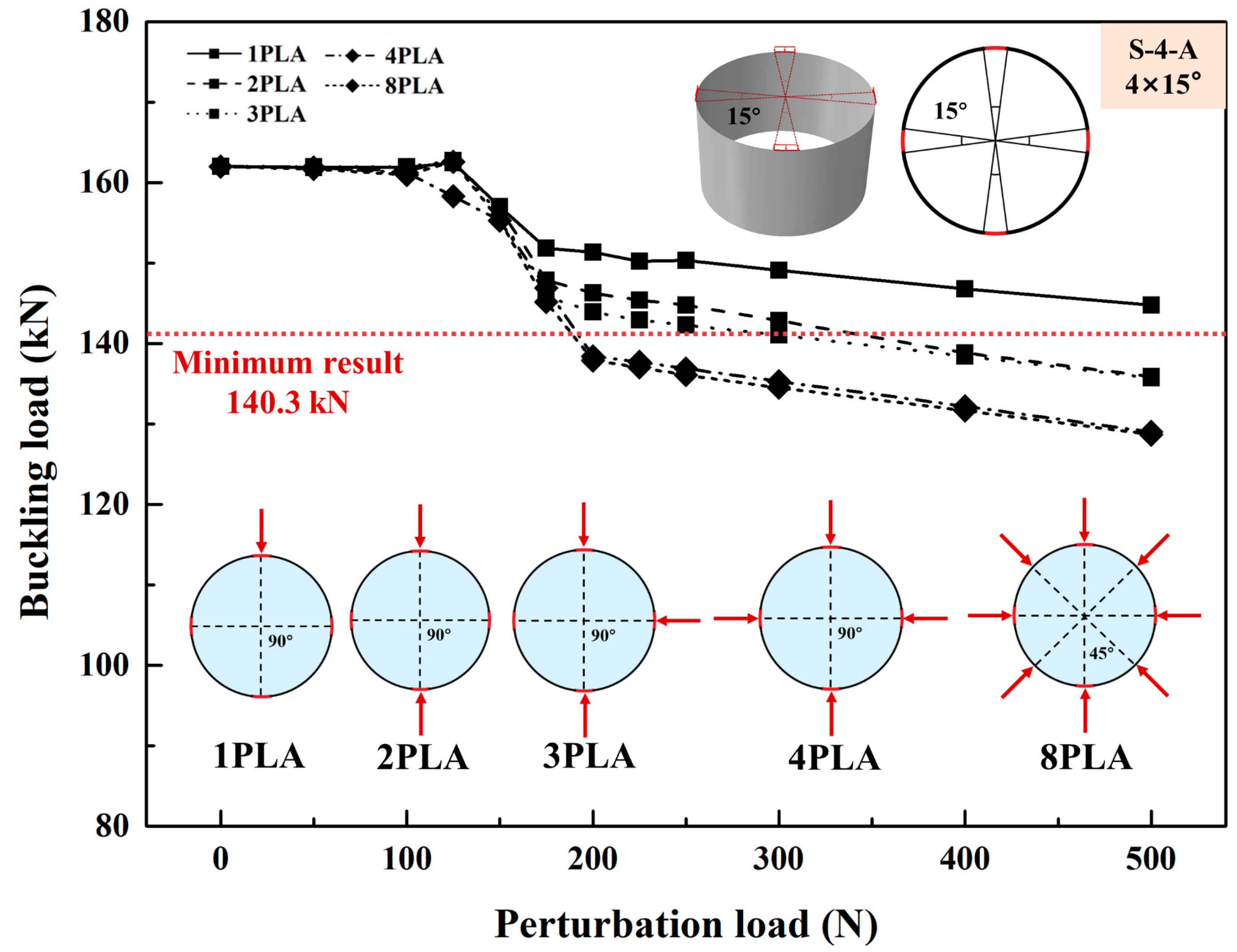
2.3. Determination of the Number of Perturbation Loads
3. Validation of LPLA
3.1. Experimental Studies
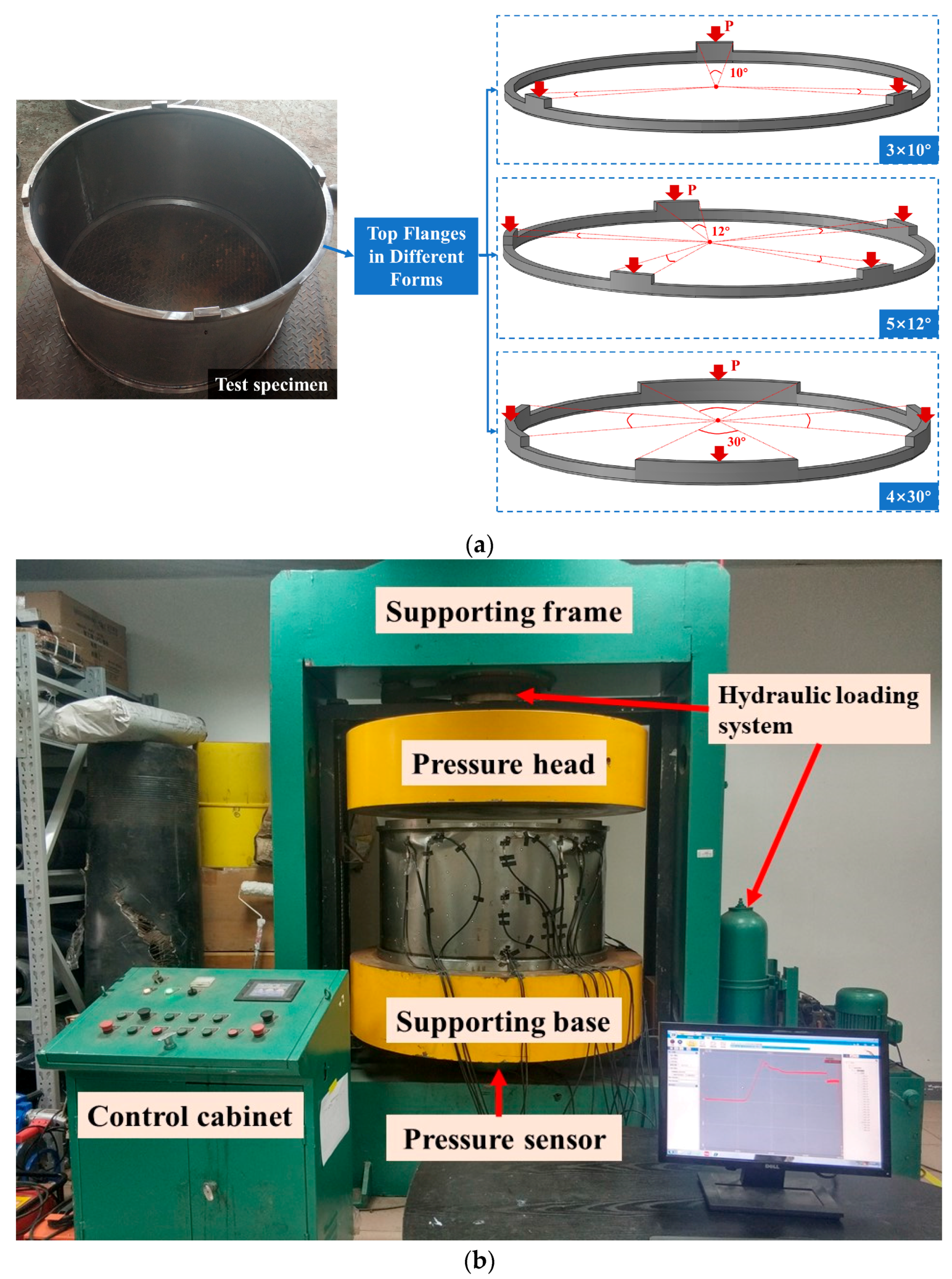
3.1.1. Test Specimens and Platform
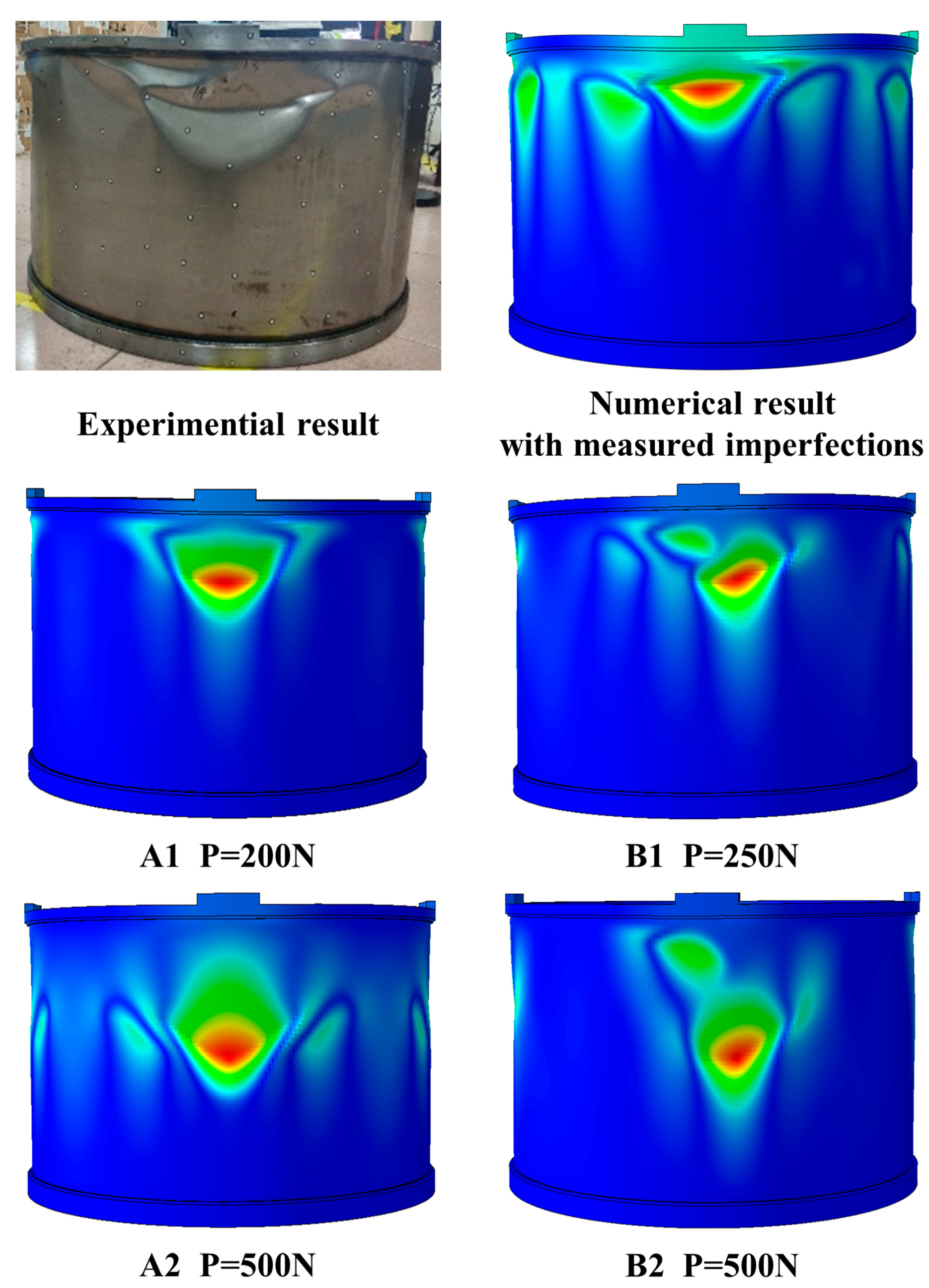
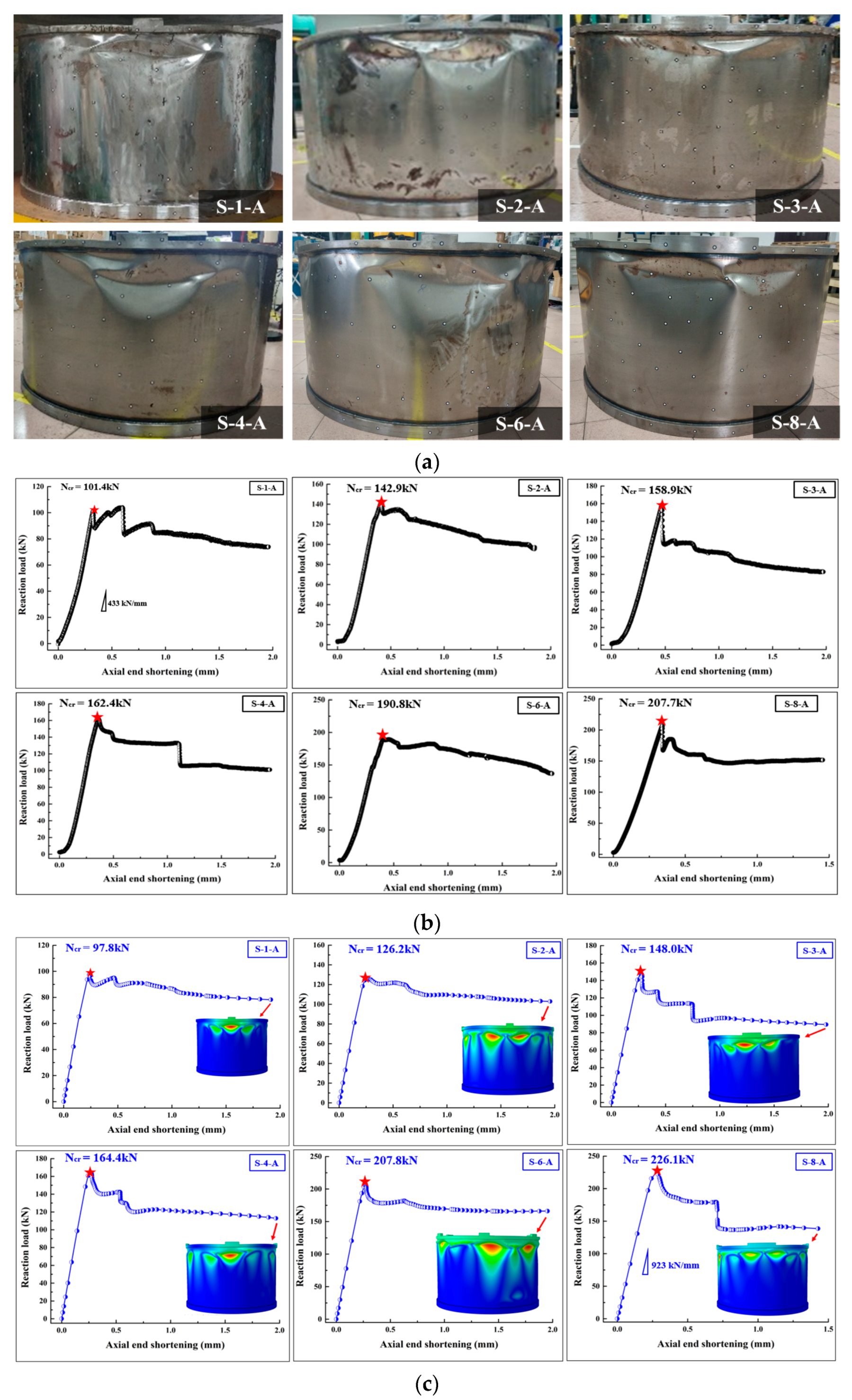
3.1.2. Results and Comparisons
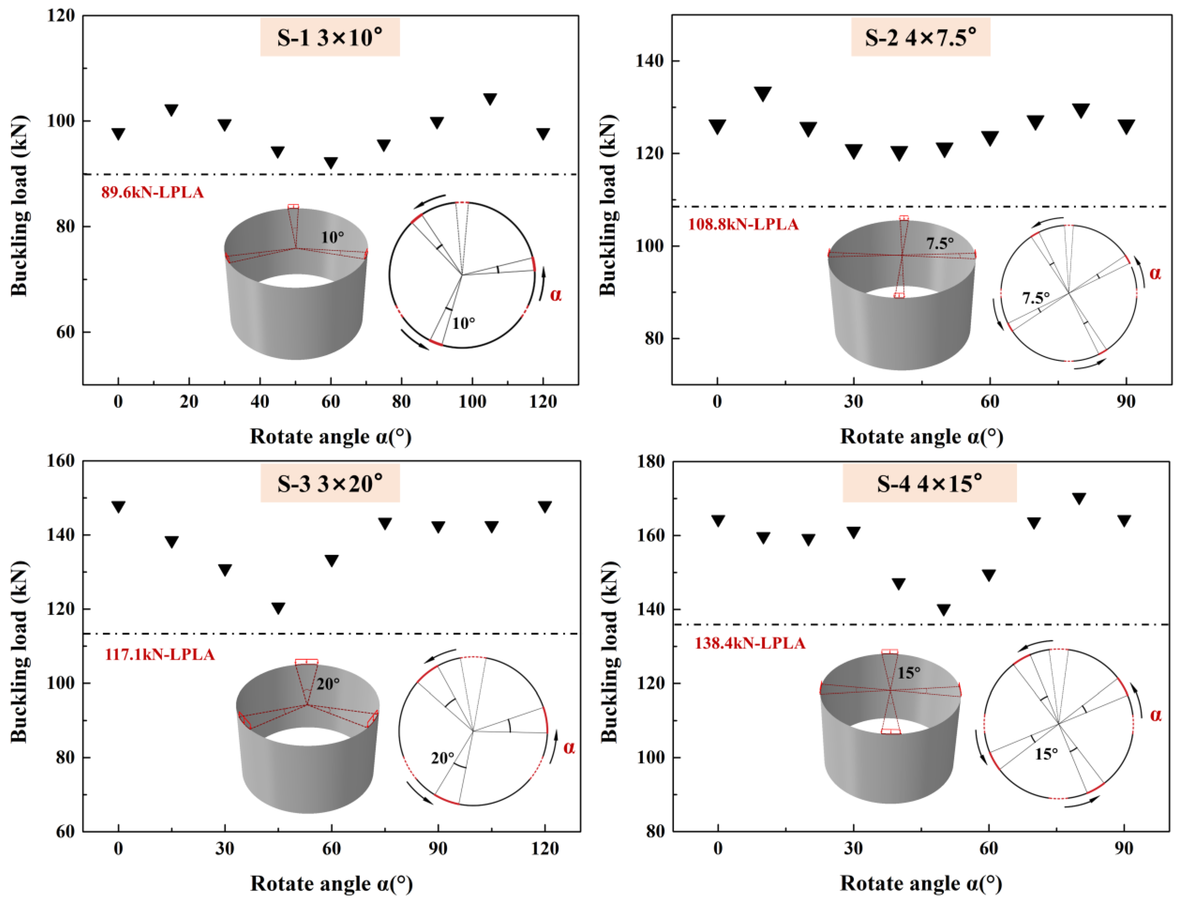
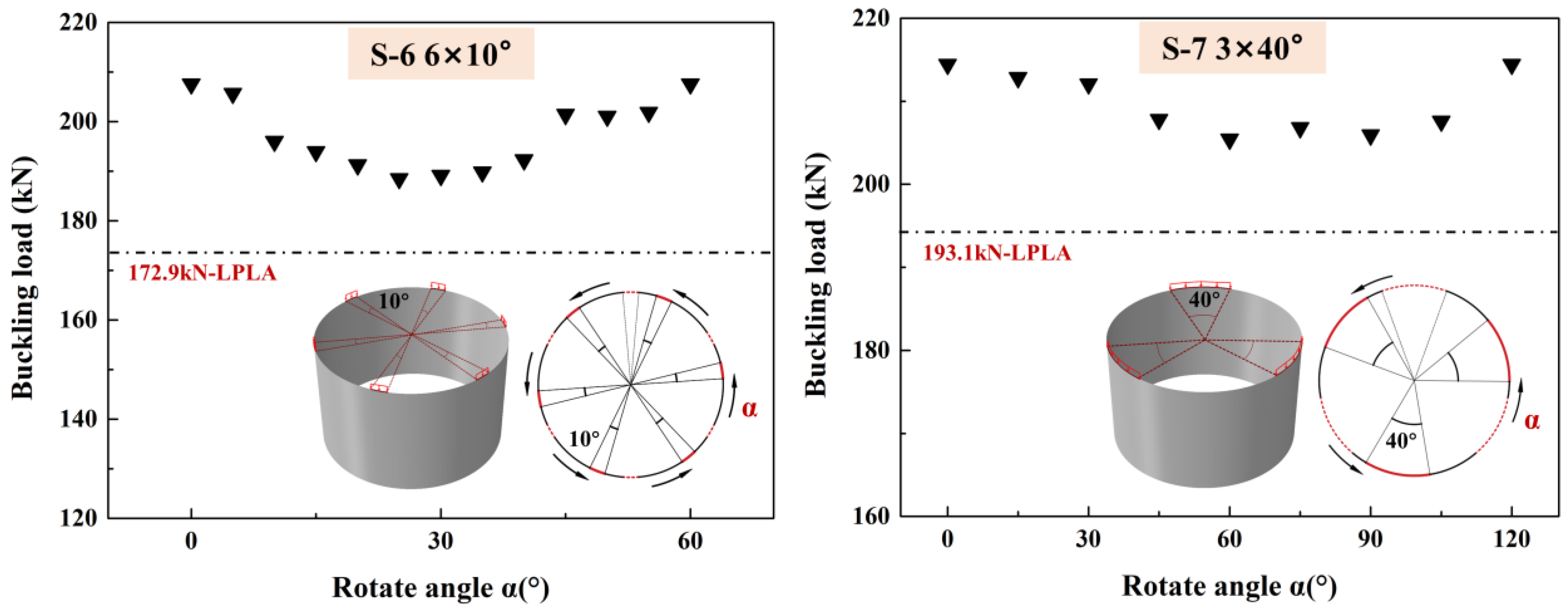
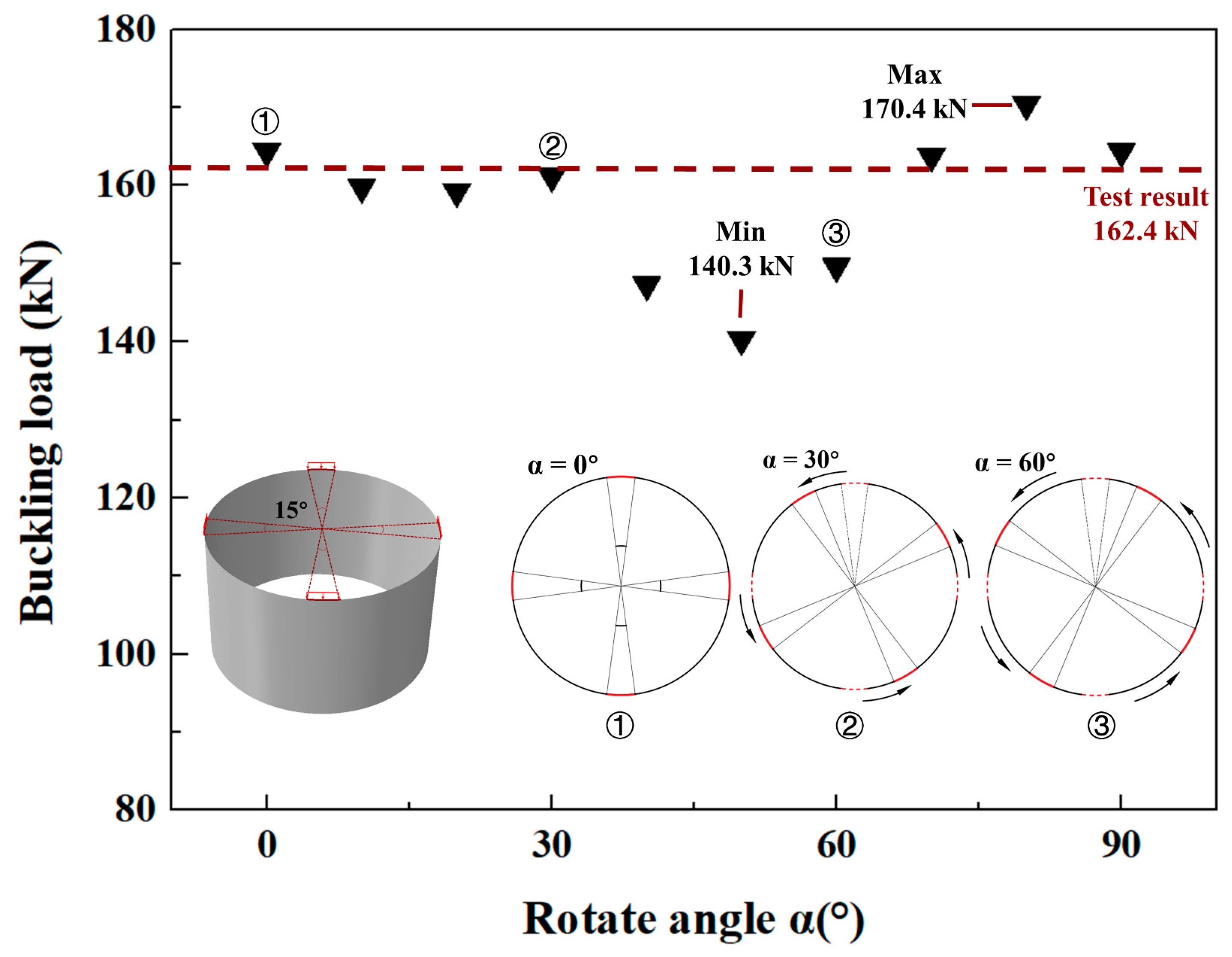
3.2. Numerical Studies with Different Imperfection Locations
3.3. Numerical Studies with Different Shell Dimensions
4. Conclusions
- (1)
- When the distribution scope of the partial axial compression loads is small, the failure mode of the cylindrical shell is local buckling. The distribution of the partial axial loads causes discrepancies in the load-carrying capacity at different locations in the shell. The shell areas directly below the loading regions have the “weakest” load-carrying capacity. Therefore, applying the perturbation loads on these areas can reflect the influence of imperfections to the greatest extent.
- (2)
- The appropriate number and location of perturbation loads in the LPLA are determined by finite element analysis. One perturbation load is applied right below the middle of each loading region of partial axial compression. The vertical distance between the application points of perturbation loads and the axial loading regions is 0.2 times the shell length.
- (3)
- The results of the LPLA are lower than the test results in all studied loading conditions. In addition, the shell buckling loads under different imperfection locations and various dimensions are all greater than the corresponding lower-bound buckling loads calculated by the LPLA. It is proven that the LPLA can provide rational and conservative lower-bound buckling loads for thin-walled cylindrical shells under partial axial compression. Therefore, the LPLA can be regarded as an appropriate design method for the partially axially compressed steel cylindrical shells in actual engineering.
Author Contributions
Funding
Data Availability Statement
Conflicts of Interest
References
- Ni, Y.; Tong, Z.; Rong, D.; Zhou, Z.; Xu, X. Accurate Thermal Buckling Analysis of Functionally Graded Orthotropic Cylindrical Shells under the Symplectic Framework. Thin-Walled Struct. 2018, 129, 1–9. [Google Scholar] [CrossRef]
- Kang, S.-Y.; Won, D.; Park, J.-S.; Kang, Y.-J.; Kim, S. Structural Behavior of Large-Diameter Cylindrical Shell with Stiffened Opening. Metals 2021, 11, 1413. [Google Scholar] [CrossRef]
- Mehta, B.; Hryha, E.; Nyborg, L.; Tholence, F.; Johansson, E. Effect of Surface Sandblasting and Turning on Compressive Strength of Thin 316L Stainless Steel Shells Produced by Laser Powder Bed Fusion. Metals 2021, 11, 1070. [Google Scholar] [CrossRef]
- Jiao, P.; Chen, Z.; Ma, H.; Miao, H.; Ou, H. Buckling Behavior Analysis of Thin-Walled Cylindrical Shell Structure Under Localized Axial Compression Load Based on Initial Imperfection Sensitivity. Int. J. Str. Stab. Dyn. 2023, 2023, 2350197. [Google Scholar] [CrossRef]
- Ma, X.; Hao, P.; Wu, H.; Bo, W.; Bi, X.; Du, K.; Ke, X. High-Fidelity Numerical Simulation and Experimental Validation of a 1600-Mm-Diameter Axial Loaded Grid Stiffened Cylindrical Shell. Int. J. Solids Struct. 2023, 273, 112262. [Google Scholar] [CrossRef]
- Meftah, S.A.; Tounsi, A.; Van Vinh, P. Formulation of Two Nodes Finite Element Model for Geometric Nonlinear Analysis of RHS Beams Accounting for Distortion and Shear Deformations. Int. J. Steel Struct. 2022, 22, 940–957. [Google Scholar] [CrossRef]
- Wagner, H.N.R.; Huehne, C.; Rohwer, K.; Niemann, S.; Wiedemann, M. Stimulating the Realistic Worst Case Buckling Scenario of Axially Compressed Unstiffened Cylindrical Composite Shells. Compos. Struct. 2017, 160, 1095–1104. [Google Scholar] [CrossRef]
- dos Santos, R.R.; Castro, S.G.P. Lightweight Design of Variable-Stiffness Cylinders with Reduced Imperfection Sensitivity Enabled by Continuous Tow Shearing and Machine Learning. Materials 2022, 15, 4117. [Google Scholar] [CrossRef]
- Koiter, W.T. The Stability of Elastic Equilibrium; Delft University of Technology: Delft, The Netherlands, 1945. [Google Scholar]
- Li, S.-C.; Zhang, Y.-C.; Chang, L.; Zhou, C.-Y.; He, X.-H. Research on Buckling Load of Cylindrical Shell with an Inclined through Crack under External Pressure and Its Solution. Metals 2023, 13, 174. [Google Scholar] [CrossRef]
- Calladine, C. Understanding Imperfection-Sensitivity in the Buckling of Thin-Walled Shells. Thin-Walled Struct. 1995, 23, 215–235. [Google Scholar] [CrossRef]
- Peterson, J.P.; Seide, P.; Weingarten, V.I. Buckling of Thin-Walled Circular Cylinders—NASA SP-8007; NASA Space Vehicle Design Criteria; NASA: Washington, DC, USA, 1968. [Google Scholar]
- Cooley, S.A.; Yang, H.; Virgin, L.N. 3D-Printing and Cylinder Buckling: Challenges and Opportunities. Proc. R. Soc. A-Math. Phys. Eng. Sci. 2023, 381, 20220035. [Google Scholar] [CrossRef] [PubMed]
- Castro, S.G.P.; Zimmermann, R.; Arbelo, M.A.; Degenhardt, R. Exploring the Constancy of the Global Buckling Load after a Critical Geometric Imperfection Level in Thin-Walled Cylindrical Shells for Less Conservative Knock-down Factors. Thin-Walled Struct. 2013, 72, 76–87. [Google Scholar] [CrossRef]
- Wagner, H.N.R.; Hühne, C.; Elishakoff, I. Probabilistic and Deterministic Lower-Bound Design Benchmarks for Cylindrical Shells under Axial Compression. Thin-Walled Struct. 2020, 146, 106451. [Google Scholar] [CrossRef]
- Arbocz, J.; Babcock, C.D. Prediction of Buckling Loads Based on Experimentally Measured Initial Imperfections. In Buckling of Structures; Budiansky, B., Ed.; Springer: Berlin/Heidelberg, Germany, 1976; pp. 291–311. ISBN 978-3-642-50994-0. [Google Scholar]
- Winterstetter, T.A.; Schmidt, H. Stability of Circular Cylindrical Steel Shells under Combined Loading. Thin-Walled Struct. 2002, 40, 893–909. [Google Scholar] [CrossRef]
- Huehne, C.; Rolfes, R.; Breitbach, E.; Tessmer, J. Robust Design of Composite Cylindrical Shells under Axial Compression—Simulation and Validation. Thin-Walled Struct. 2008, 46, 947–962. [Google Scholar] [CrossRef]
- Hao, P.; Wang, B.; Du, K.; Li, G.; Tian, K.; Sun, Y.; Ma, Y. Imperfection-Insensitive Design of Stiffened Conical Shells Based on Equivalent Multiple Perturbation Load Approach. Compos. Struct. 2016, 136, 405–413. [Google Scholar] [CrossRef]
- Wagner, H.N.R.; Huehne, C.; Niemann, S.; Khakimova, R. Robust Design Criterion for Axially Loaded Cylindrical Shells—Simulation and Validation. Thin-Walled Struct. 2017, 115, 154–162. [Google Scholar] [CrossRef]
- Arbelo, M.A.; Castro, S.G.; Kalnins, K.; Ozolins, O.; Khakimova, R.; Degenhardt, R. Experimental Characterization of Buckling Load on Imperfect Cylindrical Shells Using the Multiple Perturbation Load Approach. In Proceedings of the 13th European Conference on Spacecraft Structures, Materials and Environmental Testing, Braunschweig, Germany, 1–4 April 2014; Volume 727. [Google Scholar]
- Jiao, P.; Chen, Z.; Tang, X.; Su, W.; Wu, J. Design of Axially Loaded Isotropic Cylindrical Shells Using Multiple Perturbation Load Approach—Simulation and Validation. Thin-Walled Struct. 2018, 133, 1–16. [Google Scholar] [CrossRef]
- Arbelo, M.A.; Degenhardt, R.; Castro, S.G.P.; Zimmermann, R. Numerical Characterization of Imperfection Sensitive Composite Structures. Compos. Struct. 2014, 108, 295–303. [Google Scholar] [CrossRef]
- Asmolovskiy, N.; Tkachuk, A.; Bischoff, M. Numerical Approaches to Stability Analysis of Cylindrical Composite Shells Based on Load Imperfections. Eng. Comput. 2015, 32, 498–518. [Google Scholar] [CrossRef]
- Hao, P.; Wang, B.; Li, G.; Meng, Z.; Tian, K.; Zeng, D.; Tang, X. Worst Multiple Perturbation Load Approach of Stiffened Shells with and without Cutouts for Improved Knockdown Factors. Thin-Walled Struct. 2014, 82, 321–330. [Google Scholar] [CrossRef]
- Wang, B.; Hao, P.; Li, G.; Fang, Y.; Wang, X.; Zhang, X. Determination of Realistic Worst Imperfection for Cylindrical Shells Using Surrogate Model. Struct. Multidiscip. Optim. 2013, 48, 777–794. [Google Scholar] [CrossRef]
- Tian, K.; Wang, B.; Hao, P.; Waas, A.M. A High-Fidelity Approximate Model for Determining Lower-Bound Buckling Loads for Stiffened Shells. Int. J. Solids Struct. 2018, 148, 14–23. [Google Scholar] [CrossRef]
- Ma, W.; Sun, Z.; Wu, H.; Xu, L.; Zeng, Y.; Wang, Y.; Huang, G. Buckling Analysis of Thin-Walled Circular Shells under Local Axial Compression Using Vector Form Intrinsic Finite Element Method. Metals 2023, 13, 564. [Google Scholar] [CrossRef]
- Yang, L.; Qiu, T.; Dong, Y. Buckling Analysis of Cylindrical Shells with Variable Thickness Subjected to Non-Uniform Axial Compression by Establishing a Novel Quadratic Perturbation Technique. Int. J. Struct. Stab. Dyn. 2022, 22, 2250120. [Google Scholar] [CrossRef]
- Wang, P.; Zhu, X.; Liu, M.; Li, Y. Buckling Behaviors and Simplified Design Method for Steel Silos under Locally Distributed Axial Load. J. Constr. Steel. Res. 2017, 134, 114–134. [Google Scholar] [CrossRef]
- Jiao, P.; Chen, Z.; Ma, H.; Zhang, D.; Wu, J.; Ge, P.; Gu, Y. Buckling Test of Thin-Walled Metallic Cylindrical Shells under Locally Distributed Axial Compression Loads. In Proceedings of the Pressure Vessels and Piping Conference, Online, 3 August 2020; American Society of Mechanical Engineers: Amsterdam, The Netherlands, 2020; Volume 83839, p. V003T03A067. [Google Scholar]
- Rotter, J.M.; Cai, M.; Holst, J.M.F.G. Buckling of Thin Cylindrical Shells Under Locally Elevated Compressive Stresses. J. Press. Vessel Technol.-Trans. ASME 2011, 133, 011204. [Google Scholar] [CrossRef]
- Song, C.Y.; Teng, J.G.; Rotter, J.M. Imperfection Sensitivity of Thin Elastic Cylindrical Shells Subject to Partial Axial Compression. Int. J. Solids Struct. 2004, 41, 7155–7180. [Google Scholar] [CrossRef]
- Khelil, A. Buckling of Steel Shells Subjected to Non-Uniform Axial and Pressure Loading. Thin-Walled Struct. 2002, 40, 955–970. [Google Scholar] [CrossRef]
- Dey, T.; Ramachandra, L.S. Dynamic Stability of Simply Supported Composite Cylindrical Shells under Partial Axial Loading. J. Sound Vibr. 2015, 353, 272–291. [Google Scholar] [CrossRef]
- Jiao, P.; Chen, Z.; Ma, H.; Ge, P.; Gu, Y.; Miao, H. Buckling Behaviors of Thin-Walled Cylindrical Shells under Localized Axial Compression Loads, Part 1: Experimental Study. Thin-Walled Struct. 2021, 166, 108118. [Google Scholar] [CrossRef]
- Jiao, P.; Chen, Z.; Ma, H.; Ge, P.; Gu, Y.; Miao, H. Buckling Behaviors of Thin-Walled Cylindrical Shells under Localized Axial Compression Loads, Part 2: Numerical Study. Thin-Walled Struct. 2021, 169, 108330. [Google Scholar] [CrossRef]
- Ma, H.; Jiao, P.; Li, H.; Cheng, Z.; Chen, Z. Buckling Analyses of Thin-Walled Cylindrical Shells Subjected to Multi-Region Localized Axial Compression: Experimental and Numerical Study. Thin-Walled Struct. 2023, 183, 110330. [Google Scholar] [CrossRef]
- Castro, S.G.P.; Zimmermann, R.; Arbelo, M.A.; Khakimova, R.; Hilburger, M.W.; Degenhardt, R. Geometric Imperfections and Lower-Bound Methods Used to Calculate Knock-down Factors for Axially Compressed Composite Cylindrical Shells. Thin-Walled Struct. 2014, 74, 118–132. [Google Scholar] [CrossRef]


| Parameter | Value |
|---|---|
| Shell diameter, D (mm) | 1000 |
| Shell length, L (mm) | 530 |
| Shell thickness, t (mm) | 1.2 |
| Yield strength, ReL (MPa) | 149.4 |
| Poisson’s ratio, ν | 0.3 |
| Elastic modulus, E (GPa) | 202.4 |
| Damping factor | 1 × 10⁻⁶ |
| Shell element type | S4R |
| Shell circumferential element number | 400 |
| Cylindrical Shell | Loading Region | Experimental Results (Exp) (kN) | Numerical Results (Num) (kN) | LPLA Results (kN) | (LPLA-Exp)/Exp |
|---|---|---|---|---|---|
| S-1-A | 3 × 10° | 101.4 | 97.8 | 89.6 | −11.64% |
| S-1-B | 3 × 10° | 117.4 | 107.6 | 89.6 | −23.68% |
| S-2-A | 4 × 7.5° | 142.9 | 126.2 | 108.8 | −23.86% |
| S-2-B | 4 × 7.5° | 131.9 | 131.1 | 108.8 | −17.51% |
| S-3-A | 3 × 20° | 158.9 | 148.0 | 117.1 | −26.31% |
| S-3-B | 3 × 20° | 123.7 | 139.6 | 117.1 | −5.34% |
| S-4-A | 4 × 15° | 162.4 | 164.4 | 138.4 | −14.78% |
| S-4-B | 4 × 15° | 171.3 | 159.3 | 138.4 | −19.21% |
| S-6-A | 6 × 10° | 190.8 | 207.8 | 172.9 | −9.38% |
| S-6-B | 6 × 10° | 204.3 | 207.6 | 172.9 | −15.37% |
| S-7-A | 3 × 40° | 221.8 | 214.4 | 193.1 | −12.94% |
| S-7-B | 3 × 40° | 218.3 | 198.5 | 193.1 | −11.54% |
| S-8-A | 4 × 30° | 207.7 | 226.1 | 198.7 | −4.33% |
| TS-1-1 | 2 × 15° | 99.6 | 100.2 | 71.8 | −27.91% |
| TS-1-2 | 2 × 15° | 96.6 | 102.7 | 71.8 | −25.67% |
| TS-1-3 | 2 × 15° | 86.7 | 95.9 | 71.8 | −17.19% |
| TS-2-1 | 2 × 15° | 139.1 | 151.8 | 110.5 | −20.56% |
| TS-2-2 | 2 × 15° | 138.9 | 145.4 | 110.5 | −20.45% |
| TS-2-3 | 2 × 15° | 124.7 | 135.1 | 110.5 | −11.39% |
| Cylindrical Shell | Loading Region | Num Results (Minimum) (kN) | LPLA Results (kN) | (LPLA-Num)/Num |
|---|---|---|---|---|
| S-1-A | 3 × 10° | 92.3 | 89.6 | −2.93% |
| S-2-A | 4 × 7.5° | 120.5 | 108.8 | −9.71% |
| S-3-A | 3 × 20° | 120.6 | 117.1 | −2.90% |
| S-4-A | 4 × 15° | 140.3 | 138.4 | −1.35% |
| S-6-A | 6 × 10° | 188.5 | 172.9 | −8.28% |
| S-7-A | 3 × 40° | 205.4 | 193.1 | −5.99% |
| Cylindrical Shell | R (mm) | L (mm) | t (mm) | R/t | L/R | Loading Region | Num Results (kN) | LPLA (kN) | (LPLA-Num)/Num |
|---|---|---|---|---|---|---|---|---|---|
| S-2-A | 500 | 530 | 1.2 | 417 | 1.06 | 7.5° × 4 | 126.2 | 108.8 | −13.79% |
| S-2-A1 | 500 | 530 | 1 | 500 | 1.06 | 7.5° × 4 | 100.2 | 89.4 | −10.78% |
| S-2-A2 | 500 | 530 | 1.67 | 300 | 1.06 | 7.5° × 4 | 192.0 | 153.2 | −20.21% |
| S-2-A3 | 500 | 530 | 2.5 | 200 | 1.06 | 7.5° × 4 | 314.3 | 257.4 | −18.10% |
| S-2-A4 | 500 | 530 | 5 | 100 | 1.06 | 7.5° × 4 | 721.2 | 603.4 | −16.33% |
| S-6-A | 500 | 530 | 1.2 | 417 | 1.06 | 10° × 6 | 207.6 | 172.9 | −16.71% |
| S-6-A1 | 500 | 530 | 1 | 500 | 1.06 | 10° × 6 | 166.4 | 139.8 | −15.99% |
| S-6-A2 | 500 | 530 | 1.67 | 300 | 1.06 | 10° × 6 | 307.5 | 244.5 | −20.49% |
| S-6-A3 | 500 | 530 | 2.5 | 200 | 1.06 | 10° × 6 | 492.2 | 397.7 | −19.20% |
| S-6-A4 | 500 | 530 | 5 | 100 | 1.06 | 10° × 6 | 1123.4 | 958.8 | −14.65% |
| S-2-B1 | 500 | 500 | 1.2 | 417 | 1.0 | 7.5° × 4 | 119.5 | 109.1 | −8.70% |
| S-2-B2 | 500 | 1000 | 1.2 | 417 | 2.0 | 7.5° × 4 | 113.6 | 105.0 | −7.57% |
| S-2-B3 | 500 | 1500 | 1.2 | 417 | 3.0 | 7.5° × 4 | 113.1 | 103.9 | −8.13% |
| S-2-B4 | 500 | 250 | 1.2 | 417 | 0.5 | 7.5° × 4 | 122.6 | 109.7 | −10.52% |
| S-6-B1 | 500 | 500 | 1.2 | 417 | 1.0 | 10° × 6 | 190.5 | 173.2 | −9.08% |
| S-6-B2 | 500 | 1000 | 1.2 | 417 | 2.0 | 10° × 6 | 183.1 | 163.0 | −10.98% |
| S-6-B3 | 500 | 1500 | 1.2 | 417 | 3.0 | 10° × 6 | 183.3 | 158.6 | −13.48% |
| S-6-B4 | 500 | 250 | 1.2 | 417 | 0.5 | 10° × 6 | 195.0 | 172.8 | −11.38% |
| C-1 | 500 | 1500 | 1 | 500 | 3.0 | 5° × 2 | 18.8 | 13.4 | −28.72% |
| C-2 | 500 | 1500 | 1 | 500 | 3.0 | 5° × 2 | 15.1 | 13.4 | −11.26% |
| C-3 | 500 | 1500 | 1 | 500 | 3.0 | 30° × 2 | 40.6 | 28.9 | −28.82% |
| C-4 | 500 | 1500 | 1 | 200 | 3.0 | 30° × 2 | 30.1 | 28.9 | −3.99% |
Disclaimer/Publisher’s Note: The statements, opinions and data contained in all publications are solely those of the individual author(s) and contributor(s) and not of MDPI and/or the editor(s). MDPI and/or the editor(s) disclaim responsibility for any injury to people or property resulting from any ideas, methods, instructions or products referred to in the content. |
© 2023 by the authors. Licensee MDPI, Basel, Switzerland. This article is an open access article distributed under the terms and conditions of the Creative Commons Attribution (CC BY) license (https://creativecommons.org/licenses/by/4.0/).
Share and Cite
Ma, H.; Jiao, P.; Xu, H.; Li, X.; Chen, Z. Localized Perturbation Load Approach for Buckling Design of Thin-Walled Steel Cylindrical Shells under Partial Axial Compression. Metals 2023, 13, 1539. https://doi.org/10.3390/met13091539
Ma H, Jiao P, Xu H, Li X, Chen Z. Localized Perturbation Load Approach for Buckling Design of Thin-Walled Steel Cylindrical Shells under Partial Axial Compression. Metals. 2023; 13(9):1539. https://doi.org/10.3390/met13091539
Chicago/Turabian StyleMa, He, Peng Jiao, Huangyang Xu, Xinshuang Li, and Zhiping Chen. 2023. "Localized Perturbation Load Approach for Buckling Design of Thin-Walled Steel Cylindrical Shells under Partial Axial Compression" Metals 13, no. 9: 1539. https://doi.org/10.3390/met13091539
APA StyleMa, H., Jiao, P., Xu, H., Li, X., & Chen, Z. (2023). Localized Perturbation Load Approach for Buckling Design of Thin-Walled Steel Cylindrical Shells under Partial Axial Compression. Metals, 13(9), 1539. https://doi.org/10.3390/met13091539