Article

Fabrication of High-Entropy Alloys Using a Combination of Detonation Spraying and Spark Plasma Sintering: A Case Study Using the Al-Fe-Co-Ni-Cu System

by
Igor S. Batraev
1,
Vladimir Yu. Ulianitsky
1,
Alexandr A. Shtertser
1,*,
Dina V. Dudina
1,2,
Konstantin V. Ivanyuk
1,
Vyacheslav I. Kvashnin
1,
Yaroslav L. Lukyanov
1,
Marina N. Samodurova
2 and
Evgeny A. Trofimov
2
1
Lavrentyev Institute of Hydrodynamics SB RAS, Lavrentyev Ave. 15, Novosibirsk 630090, Russia
2
Department of Materials Science and Physical Chemistry of Materials, South Ural State University (National Research University), Lenin Ave. 76, Chelyabinsk 454080, Russia
*
Author to whom correspondence should be addressed.
Metals 2023, 13(9), 1519; https://doi.org/10.3390/met13091519
Submission received: 8 August 2023 / Revised: 22 August 2023 / Accepted: 24 August 2023 / Published: 26 August 2023

Abstract

:
The use of pre-alloyed powders as high-entropy alloy (HEA) coating precursors ensures a predetermined (unaltered) elemental composition of the coating with regard to the feedstock powder. At the same time, it is interesting to tackle a more challenging task: to form alloy coatings from powder blends (not previously alloyed). The powder-blend-based route of coating formation eliminates the need to use atomization or ball milling equipment for powder preparation and allows for the introduction of additives into the material in a flexible manner. In this work, for the first time, a HEA was obtained using detonation spraying (DS) followed by spark plasma sintering (SPS). A powder mixture with a nominal composition of 10Al-22.5Fe-22.5Co-22.5Ni-22.5Cu (at.%) was detonation-sprayed to form a multicomponent metallic coating on a steel substrate. The elemental composition of the deposited layer was (9 ± 1)Al-(10 ± 1)Fe-(20 ± 1)Co-(34 ± 1)Ni-(27 ± 1)Cu (at.%), which is different from that of the feedstock powder because of the differences in the deposition efficiencies of the metals during DS. Despite the compositional deviations, the deposited layer was still suitable as a precursor for a HEA with a configurational entropy of ~1.5R, where R is the universal gas constant. The subsequent SPS treatment of the substrate/coating assembly was carried out at 800–1000 °C at a uniaxial pressure of 40 MPa. The SPS treatment of the deposited layer at 1000 °C for 20 min was sufficient to produce an alloy with a single-phase face-centered cubic structure and a porosity of <1%. Interestingly, the hardness values of the as-sprayed and SPS-treated coatings were close to each other (~320 HV0.3). The hardness of the coatings measured in two perpendicular directions did not differ significantly. The features of the DS–SPS route of the formation of HEA coatings and its potential applications are discussed.

1. Introduction

Spark plasma sintering (SPS) has proven to be a versatile method of the electric current-assisted treatment of powders [1,2,3] and bulk objects [4,5,6]. Powders can be consolidated into bulk materials with a controlled density within short processing times, while bulk samples or assemblies can be structurally modified using electric current heating. The potential of SPS for the processing of metallic materials has been recognized [7,8]. Using SPS, it is possible to produce bulk alloys from a mixture of components by combining the sintering and alloy formation stages. The effect of electric-current-mediated heating can be reflected in the enhanced kinetics of alloying between metals [9].
High-entropy alloys (HEAs) have attracted attention as metallic materials possessing higher strength and hardness than pure metals and conventional alloys [10,11,12]. While metallic glasses crystallize upon reaching the crystallization temperature, HEAs can be obtained in the thermally stable form (provided the samples are properly annealed). In comparison with metallic glasses, HEAs can offer better ductility in the bulk state.
The SPS method has recently been used for the fabrication of HEAs [13,14,15]. Most commonly, the powders processed by SPS to form a HEA are pre-alloyed and prepared via mechanical alloying or gas atomization. As mechanical alloying is usually a time-consuming process and contaminants can easily be introduced into the powder material, a tempting alternative would be to avoid the pre-alloying stage. Recently, successful attempts to produce HEAs from unalloyed mixtures of components using SPS have been reported [16,17]. The formation of a liquid phase played a key role in the structure formation of the alloys. Zhang et al. [16] produced an AlCoCrFeNi HEA consisting of a face-centered cubic (fcc) phase and a duplex body-centered cubic (bcc) structure. Melting of aluminum facilitated the diffusion processes during SPS. Waseem et al. [17] presented the powder metallurgy processing of refractory WxTaTiVCr HEAs and their derivatives from powder blends prepared in a shaker mill. It was noted that, during SPS, liquid-phase sintering was realized due to melting of the locally formed Ti-Cr-based or Ti-Cr-V-based alloys. The liquid phase was suggested to form at highly localized points within the sample.
Along with bulk HEAs, coatings made of HEAs are of scientific and technological interest [18,19,20]. Coatings can be formed through sintering of a layer to a substrate. In this case, the powder to form a coating is poured into a sintering die, into which the substrate is also placed. For example, CrFeCoNiCu HEA and ceramic-reinforced CrFeCoNiCu HEA coatings were obtained via SPS in [21]. The thickness of the coating layer was 1.5 mm. Another possible way to form a coating is to combine a thermal spray method with SPS: to deposit a composite layer on a substrate via powder spraying and adjust the alloy phase composition and structure by the subsequent SPS treatment. This approach was applied to coatings obtained via flame spraying [22] and cold spraying [23,24]. The SPS treatment allowed conducting the synthesis in the layers made of reactants and improving the coating structure by eliminating pores and macrodefects [24]. The “thermal spray deposition-SPS treatment” fabrication route of an alloy coating can be selected when a thin coating is necessary, since forming a thin uniform powder layer in a sintering die using a simple pouring procedure is a difficult task. The advantage of pre-alloyed powders as HEA coating precursors (feedstock materials for thermal spraying) is the preservation of the coating composition. The concentrations of the metals in the coatings are normally the same as those in the pre-alloyed feedstock powder, provided no metal evaporation occurs during spraying. However, it is interesting to tackle a more challenging task, to form alloy coatings from powder blends (not previously alloyed powders). The powder-blend-based route of the coating formation eliminates the need to use atomization or ball milling equipment and allows for the introduction of additives into the material in a flexible manner (immediately prior to spraying).
Detonation spraying (DS) belongs to the group of thermal spray methods and is based on heating and acceleration of powder particles by the products of detonation of oxygen–fuel mixtures [25]. The particles reach the substrate in the molten or partially molten state. The presence of a molten surface layer on a solid particle facilitates the bond formation with the substrate and previously deposited layers. By varying the oxygen/fuel ratio of the gaseous mixture, the reactions of the metals with the spraying atmosphere can be controlled. If the oxygen concentration in the detonation products is low, the particles of metals do not oxidize during the process, and purely metallic coatings can be obtained. Studies on the formation of HEAs via DS are still scarce. Liao et al. [26] reported the formation of HEA coatings via DS of a pre-alloyed powder obtained via gas atomization. In our previous investigations, DS has been used to form multicomponent metallic coatings [27,28]. Further treatment with a laser was used to complete the alloy formation in [28].
The Al-Fe-Co-Ni-Cu alloys have attracted the attention of researchers due to the possibility of achieving promising properties [29,30,31]. The Al-Fe-Co-Ni-Cu HEA matrix composites are also of interest [32,33]. The presence of a low-melting-point metal, Al, in the system allows conducting liquid-phase-assisted processes of alloying upon heat treatment while staying in the moderate temperature range.
The goal of the present work was to trace the structural evolution of coatings obtained by DS of an Al-Fe-Co-Ni-Cu mixture during SPS treatment and demonstrate the possibility of forming a HEA coating. The selection of the composition for the present study, 10Al-22.5Fe-22.5Co-22.5Ni-22.5Cu (at.%), was based on results obtained by Das et al. [29], who prepared this alloy using mechanical alloying, cold pressing, and sintering. In their work, the formation of an alloy with excellent mechanical properties was reported.

2. Materials and Methods

Commercially available Al, Fe, Co, Ni, and Cu powders were used in the experiments. The starting materials were aluminum (99.7%), carbonyl iron (99.9%), electrolytic cobalt (99.5%), carbonyl nickel (99.9%), and electrolytic copper (99.7%). Each of the starting powders was sieved to separate the fraction <20 μm. The SEM micrographs demonstrating the morphology of the powders can be found in [27]. The starting powder mixtures were prepared via mixing in a custom-made low-energy device. The main element of this device is a rotating cylinder containing steel balls. The mixing time was 3 h.
DS of the 10Al-22.5Fe-22.5Co-22.5Ni-22.5Cu (at.%) mixture was conducted on a computer-controlled detonation spraying set-up (CCDS2000, Novosibirsk, Russia) [24]. Acetylene was used as a fuel, and oxygen was an oxidizer. The O2/C2H2 molar ratio during DS was 1.0. The acetylene–oxygen mixture of this composition produces detonation products of reducing character, thus preventing the oxidation of the sprayed metals. Nitrogen was used as a carrier gas. For the deposition, a profiled two-section barrel of variable cross-section with a combustion chamber 20 mm in diameter and 650 mm long and a muzzle acceleration section (nozzle) 16 mm in diameter and 300 mm long was used. The use of a barrel with a conical constriction at the junction of the combustion chamber and the booster nozzle makes it possible to increase the degree of melting of the sprayed powder material. This effect was described in detail in [34]. The coatings were deposited at a stand-off distance of 100 mm. Coatings ~500 μm thick were obtained. The coatings were deposited on sand-blasted carbon-steel substrates via radial scanning on a three-axis manipulator. A powder of Al2O3 400–500 μm in size was used for the sand-blasting operation. The surface was further cleaned by a flow of compressed air. The roughness of the steel substrates after sand-blasting was Rz = 30 μm.
Cylindrical samples 10 mm in diameter were machined from the coated steel plates to fit the SPS tooling. SPS treatment of the coating/substrate assemblies was carried out using a Labox 1575 apparatus (SINTER LAND Inc., Nagaoka, Japan) under conditions of dynamic vacuum. A graphite die and graphite punches were used. The temperature during the process was measured by a pyrometer (CHINO, Tokyo, Japan) focused on a near-through hole in the die wall. The measured temperatures during SPS were 800, 900, and 1000 °C. The applied uniaxial pressure was 40 MPa. The holding time at the maximum temperature was 20 min. The heating rate in all experiments was 80 °C min−1. The residual pressure in the chamber during the soaking stage was 10 Pa. Graphite foil was placed between the surface of the tooling and the sample to avoid sticking of the sample to the tooling components. A schematic of the SPS tooling with a substrate/coating sample is shown in Figure 1a. A general view of the substrate/coating samples machined from the detonation-coated plates is shown in Figure 1b.
The X-ray diffraction (XRD) patterns of the powders, as-sprayed coating, and SPS-treated samples were recorded using a D8 ADVANCE diffractometer (Bruker AXS, Karlsruhe, Germany) with Cu Ka radiation.
Samples for structural observations and hardness measurements were made using standard metallographic techniques. Samples with a polished surface of the coatings and polished cross-sections were prepared. The microstructure of the coatings was studied using scanning electron microscopy (SEM) using a Merlin microscope (Zeiss, Oberkochen, Germany) equipped with an energy-dispersive spectroscopy (EDS) unit. The quantitative analysis was carried out on the cross-sections of the coatings. The spectra were collected from areas 250×300 μm2 in size. Coatings in the as-sprayed state and those after the SPS treatment were analyzed.
The porosity of the as-sprayed coatings and SPS-treated samples was determined from the optical images of the cross-sections of the samples using OLYMPUS Stream Image Analysis software, “Stream Essentials 1.9.1” (Tokyo, Japan). The optical images were obtained on an OLYMPUS GX-51 metallographic microscope (Tokyo, Japan).
Vickers hardness of the coatings was measured using a DuraScan 50 hardness tester (EMCO-TEST, Kuchl, Austria) at a load of 0.3 kg. The hardness was measured in two directions by making indentations normal and parallel to the substrate/coating interface.

3. Results

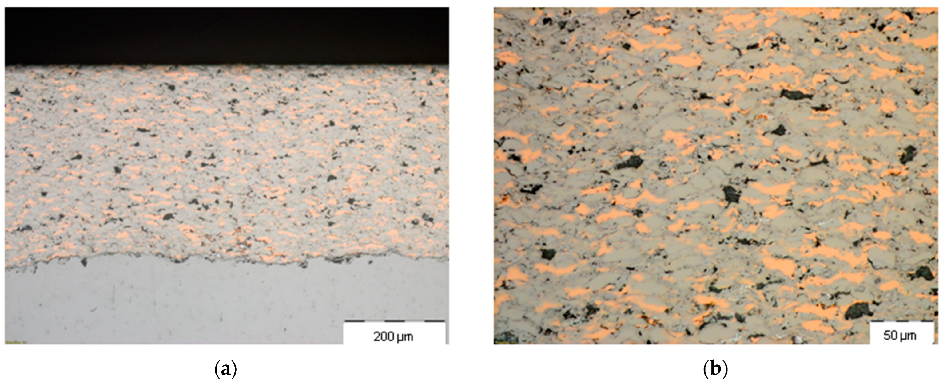
Visual observations of the samples indicated that, after SPS, the coating layers changed color, from reddish (caused by the presence of unalloyed copper regions in the as-sprayed coating) to gray. Based on the change in color, the formation of an alloy in the coating during SPS could be assumed. Figure 2 shows the optical images of the cross-section of the as-sprayed coating taken at different magnifications. In the microstructure of the coating, the islands of orange color correspond to particles of copper. Other metallic components are difficult to distinguish in the optical images.
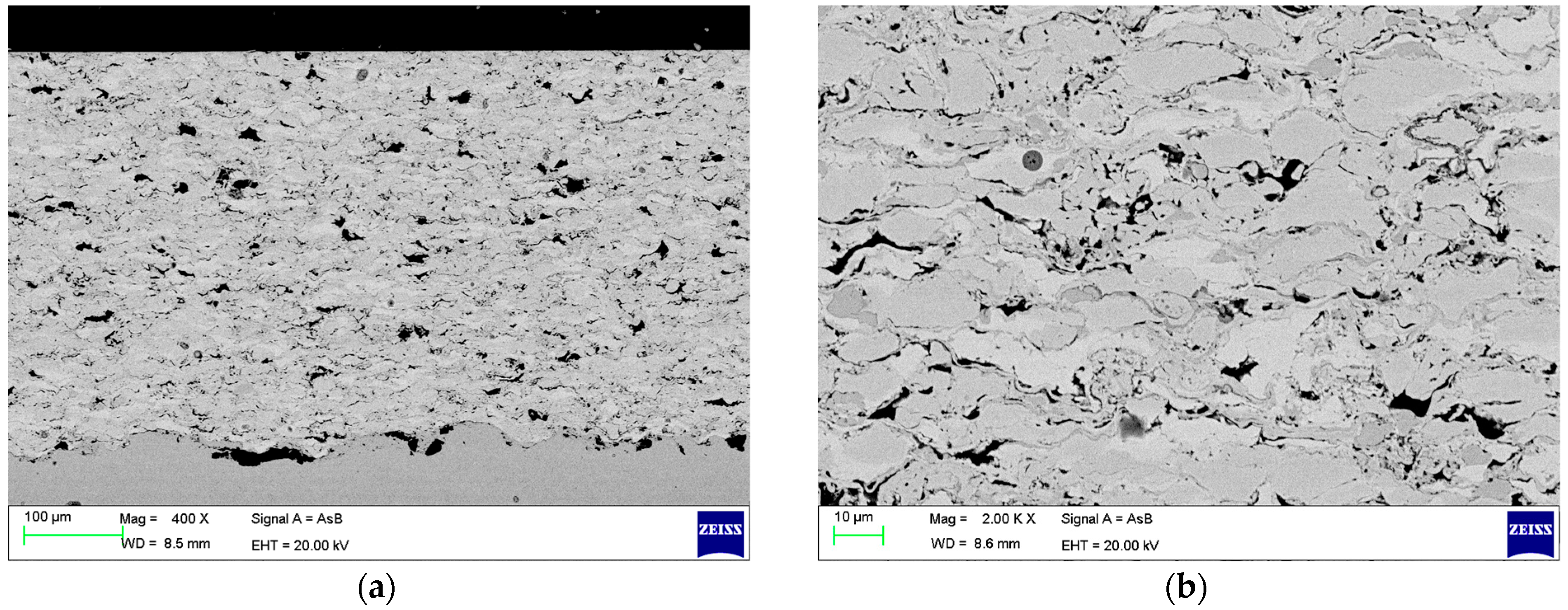
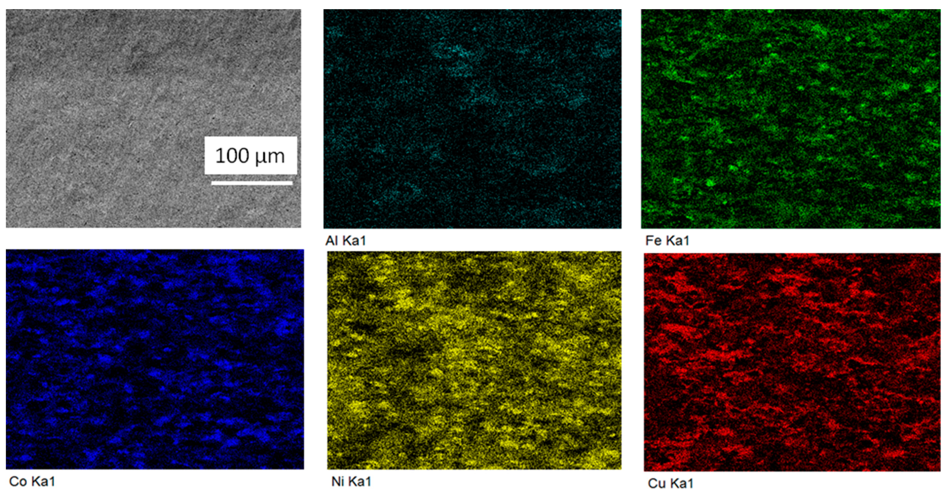
The occurrence of the alloying processes during the SPS treatment was further confirmed using XRD, SEM, and EDS in the elemental mapping mode. Figure 3a shows a SEM micrograph of the coating layer (general view). It is seen that the layer forms an intimate contact with the substrate. The dark particles at the interface between the steel substrate and the coating are those of Al2O3 used for blasting the substrate surface before the deposition. As demonstrated in Figure 3b, the coating has a lamellar structure composed of the flattened particles of the metals. The contrast in the back-scattered electron (BSE) image indicates the presence of several phases. Both optical microscopy and SEM indicate the formation of the tight interface between the substrate and the deposited layer: no pores or cracks are visible at the interface. Figure 4 demonstrates the results of the elemental mapping of an area of the as-sprayed coating. Separate particles of metallic components are seen in the structure of the layer.
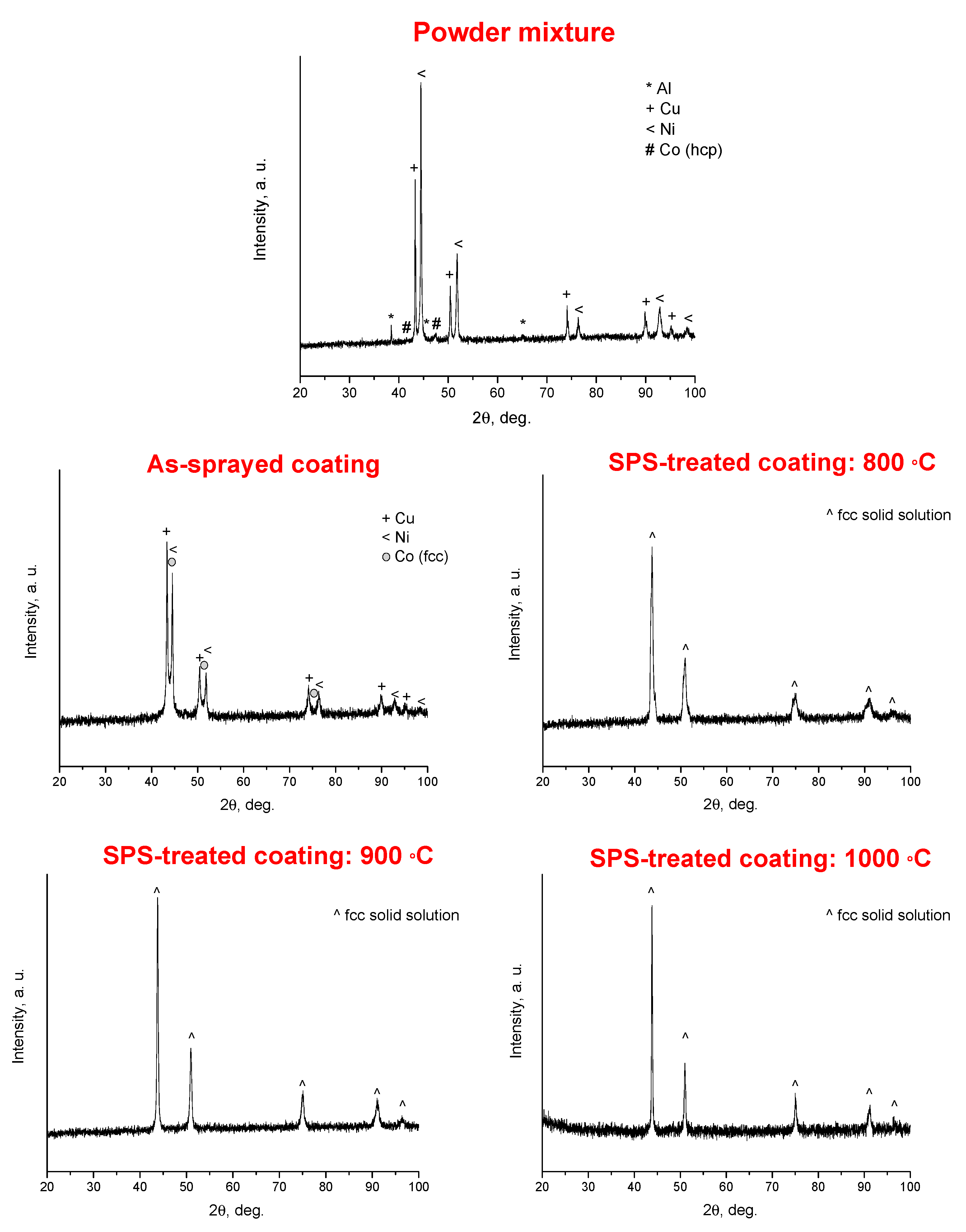
Figure 5 shows the XRD patterns of the powder mixture, as-sprayed coating, and coatings treated by SPS at different temperatures. In the pattern of the powder mixture, reflections of the metallic components were detected: Al, Ni, hexagonal close-packed (hcp) Co, and Cu. Due to the small crystallite size of the carbonyl Fe powder, the lines of bcc iron could not be distinguished in the pattern of the powder mixture. In the as-sprayed state, the reflections of Al were no longer visible, which indicates the beginning of the alloying processes between the metals. Therefore, the as-sprayed state can be considered as an early stage of alloying. Metallic cobalt is likely to acquire the fcc state due to the fast cooling of the deposited layer. The reflections on the pattern of the coating SPS-treated at 800 °C are asymmetrical, which indicates further alloying between the metals. After SPS at 900 °C and 1000 °C, the coatings demonstrated symmetrical XRD reflections of a fcc solid solution. As the SPS temperature was increased, the size of the crystallites of the metals increased, and the solid solution became more uniform in composition. Both these factors contributed to the narrowing of the XRD peaks. While the patterns of the samples treated at 900 °C and 1000 °C are quite similar to each other, there are microstructural differences between the samples.
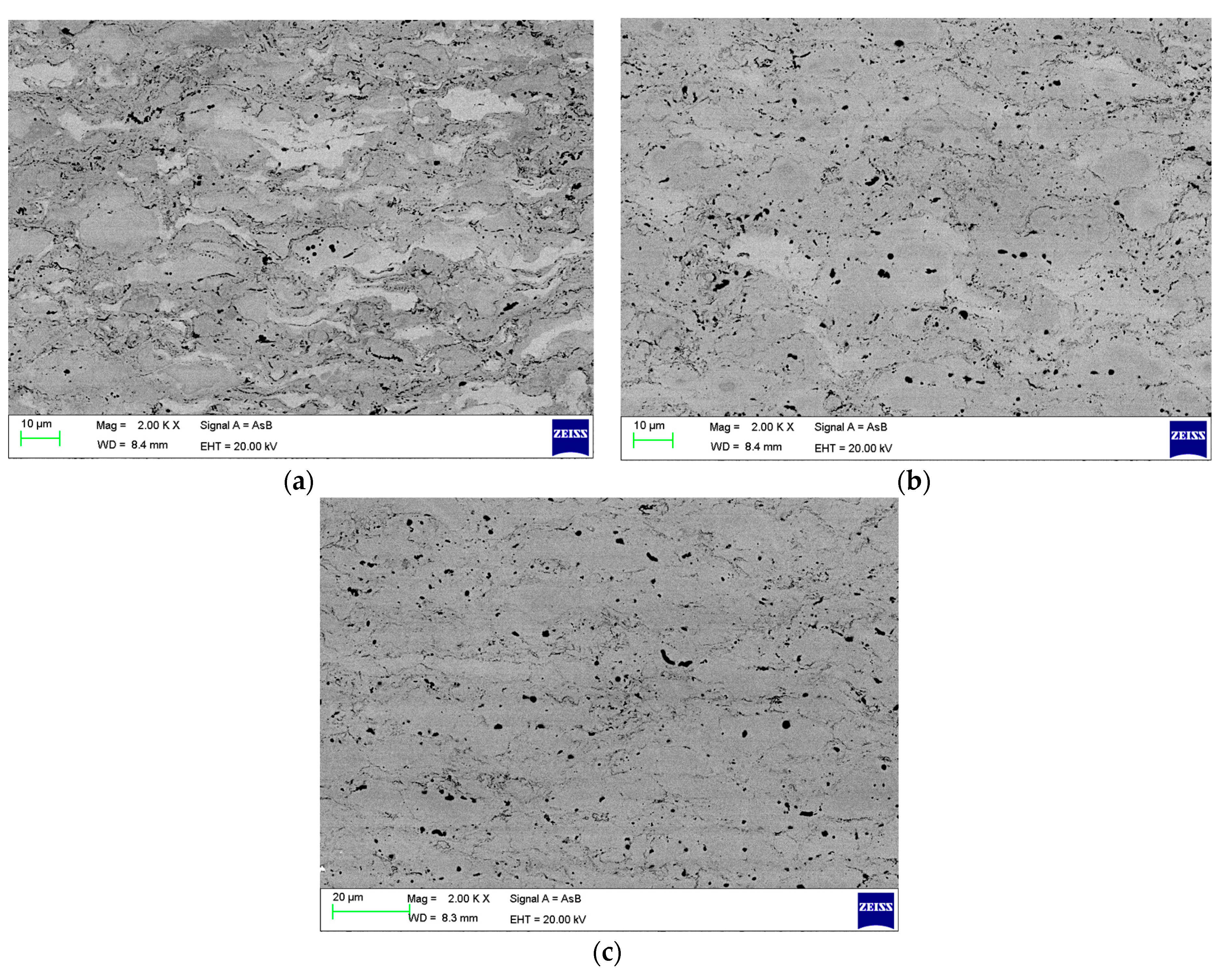
Figure 6 shows the SEM images of the microstructure of the SPS-treated coatings (the images were taken in BSE mode). As the SPS temperature was increased, the coating became more homogeneous. A distinct lamellar structure is still present in the coating treated at 800 °C (Figure 6a). After treatment at 900 °C, fewer lamellae are seen in the microstructure, the boundaries between them disappearing (Figure 6b). The microstructure of the coatings treated at 1000 °C is that of a bulk single-phase alloy (Figure 6c). Noteworthy is the reduction of porosity of the coatings after the SPS treatment, which becomes evident from the comparison of the cross-sectional microstructures of the as-sprayed (Figure 3b) and treated (Figure 6) coatings (the black spots on the images correspond to pores).
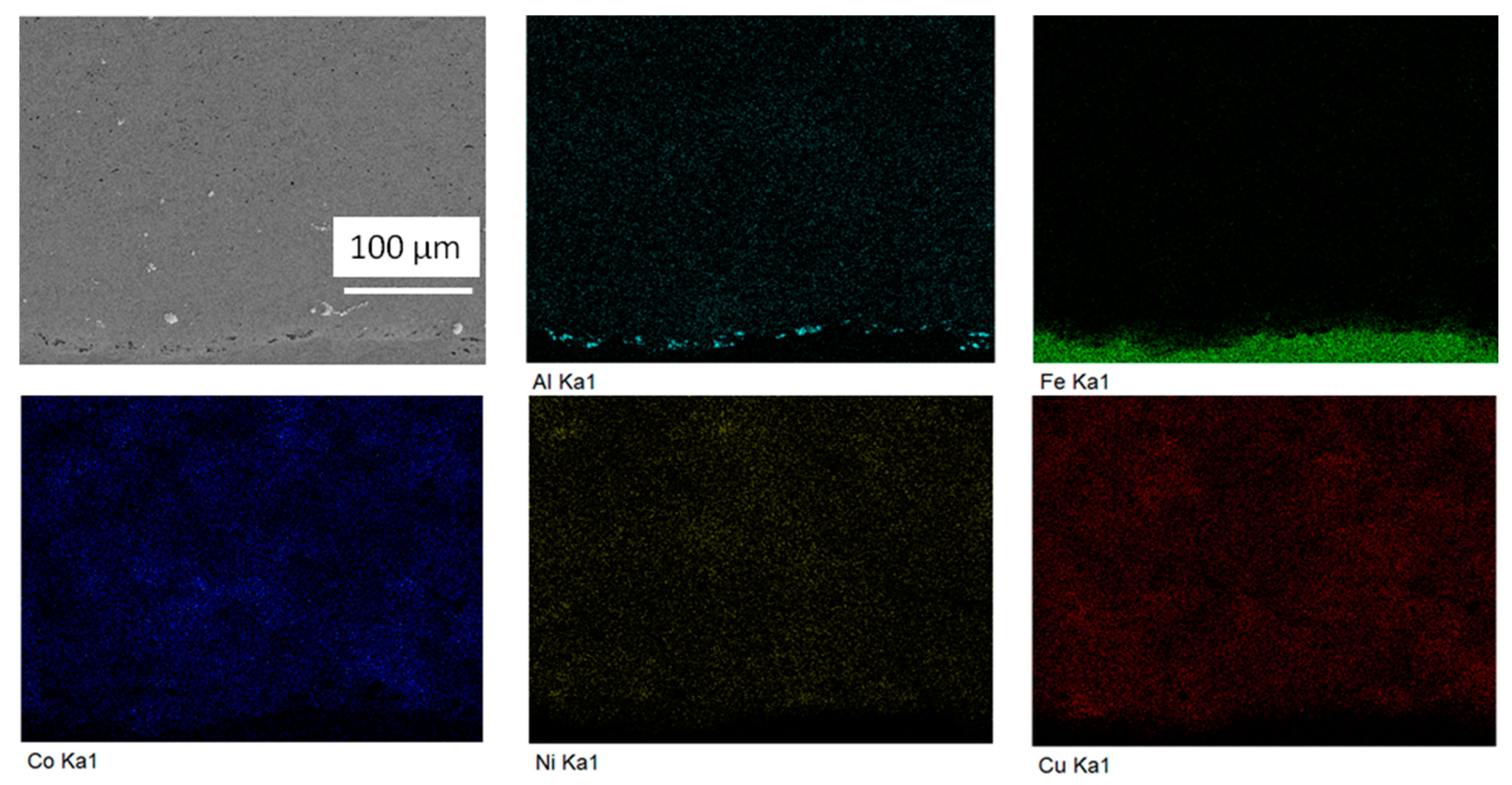
For the structural characterization of the SPS-treated coatings, the optical microscopy data were also useful, as the contrast in the optical images is related to the chemical composition. As seen in Figure 7, the SPS-treated coating is more homogeneous than the as-sprayed material. Some Cu-rich areas (those of yellow tinge) are still present in the alloy. The structural evolution of the alloy with the SPS temperature is also seen in the elemental maps of the coatings treated at 800 °C (Figure 8) and 1000 °C (Figure 9). The size of the single metal-rich islands in the microstructure of the alloy treated by SPS at 800 °C is smaller than that in the as-sprayed layer.
Coatings in the as-sprayed state and those after the SPS treatment were analyzed using EDS by recording spectra from areas of the cross-section. The measured concentrations of the metals in the as-sprayed and SPS-treated coatings were very close to each other. The unchanged composition of the coatings could have been expected, as the SPS treatment did not cause any material loss from the coating. The elemental composition of the deposited layer was found to be (9 ± 1)Al-(10 ± 1)Fe-(20 ± 1)Co-(34 ± 1)Ni-(27 ± 1)Cu (at.%), which is different from that of the feedstock powder. The concentration of the metals was averaged from the data obtained on the as-sprayed and SPS-treated coatings. The detected compositional deviation is due to the differences in the deposition efficiencies of the metals during DS [26,27]. Despite the compositional deviations, based on the definitions of [10], the deposited layer was still suitable as a precursor for a HEA as the configurational entropy of the obtained composition was close to 1.5R, where R is the universal gas constant.
Table 1 summarizes the porosity and Vickers hardness of the as-sprayed and SPS-treated coatings. Interestingly, the hardness values of the as-sprayed and SPS-treated coatings are close to each other (~320 HV0.3). The hardness was measured in two perpendicular directions (on the cross-sections and polished surfaces of the coatings). No significant differences between the measured values were detected. So, the presence of a lamellar structure in some samples did not affect their hardness. While the hardness of the coatings was not substantially influenced by the SPS temperature, the formation of a single-phase structure of the alloy is important for other properties of the alloy (strength, ductility, and corrosion resistance).

4. Discussion

The obtained results should be discussed in the context of the phase composition and hardness of the alloys, the advantages of the selected processing route, and the methodological implications of the present work.
As mentioned above, a composite layer of metallic components on a substrate can be formed using a thermal spray method. Here, the possibility of the formation of oxide phases needs to be considered. The problem of oxidation of the sprayed material is known in the practice of plasma spraying. For example, during atmospheric plasma spraying of a mechanically alloyed equiatomic AlCoCrFeNi HEA, a complex alloy-oxide coating formed [18]. As shown in the present work, HEAs obtained by DS under reducing conditions are free from oxide phases (no phases other than the target solid solution were detected in the coatings by XRD). It should also be noted that, compared with laser cladding with powder blends as feedstock materials [35], the fabrication route described in the present work has the advantage of eliminating pores and cracks in the coating.
The measured hardness of the HEA obtained in the present work is much higher than the hardness of the alloy with a close composition obtained via cold pressing and sintering by Das et al. [29]. In that work, the Al10(FeCoNiCu)90 alloy consisted of two phases after mechanical alloying. The heat treatment of the cold-pressed powder compacts was conducted at 1100 °C for 48 h. After heat treatment in a furnace, the alloy transformed into a single-phase fcc solid solution. The hardness of the sintered alloy was 160 HV0.5. A much shorter high-temperature exposure of the material in the present work allowed maintaining its high hardness. At the same time, the hardness of the HEA obtained in the present work is lower than that of the equiatomic HEA obtained via gas atomization, milling, and SPS in [33]. The latter consisted of two phases: fcc and bcc. The difference in the hardness can be due to the differences in both elemental and phase composition of the HEAs.
The solid solution phase of HEAs may depend on the processing route of the alloy [36,37]. For example, cast AlCoCrFeNi alloys were composed of fcc and bcc crystalline phases [36]. The major phase in the as-cast, quenched, and remelted alloys was the bcc solid solution. The annealed alloy showed a much higher concentration of the fcc phase than alloys in the as-cast, quenched, and remelted states. Fu et al. [37] showed that the phase compositions of HEAs obtained using hot pressing (HP) and SPS were not the same. HP was conducted at 1000 °C for 1 h, while the SPS process lasted only 8 min at the same (measured) temperature. The pressure of 30 MPa was applied in both cases. The hot-pressed Al0.6CoNiFe bulk alloy was composed of a bcc phase (major phase) and a fcc phase (minor phase). The alloy of the same elemental composition obtained via SPS had a fcc phase as the major phase. The alloy formed via SPS exhibited a lower compressive strength but a significantly higher plasticity than the hot-pressed counterpart. In view of the above, on the design map of HEAs, the DS–SPS route can offer new sets of properties. The influence of the DS deposition on the properties of HEAs obtained by SPS is the formation of a composite layer with a reduced porosity and the occurrence of the initial stages of alloying at the particle contacts even before the SPS treatment.
In our opinion, this work, in addition to results concerning the formation of an Al-Fe-Co-Ni-Cu HEA with a high hardness in the form of a thin coating on a steel substrate, has methodological implications for fundamental studies of SPS processes. In recent years, the SPS mechanisms related to local effects and the intrinsic role of electric current have been actively discussed [2,3,38,39]. The influence of electric current on the formation of reaction products (intermetallics) between metals [9,40] and interdiffusion (in the case of metals of unlimited solubility) [41] has been the subject of research. Usually, in such studies, thin plates or foils of metals are stacked together and subjected to SPS. However, the local effects related to the point contacts and surface roughness of the plates can arise, complicating the elucidation of the intrinsic effects of electric current. If layers pre-deposited by DS are used instead of foils or plates, these problems can be overcome, as tight interfaces can be formed. As DS is very flexible in terms of the total coating thickness and the thickness of the component layers, assemblies with different architectures can be fabricated. These composite structures can serve as starting reactants for the model SPS experiments to investigate the intrinsic role of electric current in the reaction/alloying advancement between metals. If a composite structure is made of different metals, the reactivity of several diffusion couples can be studied within a single SPS run and reliably compared. In multicomponent systems, the alloying stages and sequences during SPS can also be traced.

5. Conclusions

In the present work, an Al-Fe-Co-Ni-Cu HEA was obtained using a combination of DS and SPS. A blend of metallic powders of the 10Al-22.5Fe-22.5Co-22.5Ni-22.5Cu (at.%) composition was used as a feedstock material for DS. Al-Fe-Co-Ni-Cu coatings ~500 μm thick were deposited on steel substrates. The as-sprayed coating had a composite structure corresponding to an early stage of alloy formation and consisted of particles of metallic components. The deposited layer had a composition of (9 ± 1)Al-(10 ± 1)Fe-(20 ± 1)Co-(34 ± 1)Ni-(27 ± 1)Cu (at.%). The deviation of the composition from the feedstock powder was due to the differences in the deposition efficiencies of the metals during DS. The subsequent SPS treatment of the substrate/coating assembly was carried out at 800–1000 °C at a uniaxial pressure of 40 MPa. The SPS treatment of the deposited layer at 1000 °C for 20 min was sufficient for producing an alloy with a single-phase fcc structure and a porosity of <1%. The hardness values of the as-sprayed and SPS-treated coatings were close to each other (~320 HV0.3). The hardness of the coatings was measured in two perpendicular directions; no significant differences between the measured values were observed. While the present work was conducted as a case study of a particular system, the possibility of modifying the structure and properties of detonation sprayed metallic materials by the post-spray SPS treatment can be used for alloys and composite structures of variable compositions.

Author Contributions

Conceptualization, D.V.D., E.A.T., and V.Y.U.; methodology, I.S.B. and V.Y.U.; investigation, D.V.D., A.A.S., I.S.B., K.V.I., V.I.K., M.N.S., and Y.L.L.; writing—original draft preparation, D.V.D.; writing—review and editing, A.A.S., E.A.T., and M.N.S.; supervision, project administration, funding acquisition, M.N.S. All authors have read and agreed to the published version of the manuscript.

Funding

This research was funded by the Russian Science Foundation, grant No. 20-19-00304, https://rscf.ru/project/20-19-00304/ (accessed on 8 August 2023).

Data Availability Statement

Data can be made available upon request.

Conflicts of Interest

The authors declare no conflict of interest. The funders had no role in the design of the study; in the collection, analyses or interpretation of data; in the writing of the manuscript; or in the decision to publish the results.

References

  1. Guillon, O.; Gonzalez-Julian, J.; Dargatz, B.; Kessel, T.; Schierning, G.; Räthel, J.; Herrmann, M. Field-assisted sintering technology/spark plasma sintering: Mechanisms, materials, and technology developments. Adv. Eng. Mater. 2014, 16, 830–849. [Google Scholar] [CrossRef]
  2. Tokita, M. Progress of spark plasma sintering (SPS) method, systems, ceramics applications and industrialization. Ceramics 2021, 4, 160–198. [Google Scholar] [CrossRef]
  3. Mukasyan, A.S.; Rogachev, A.S.; Moskovskikh, D.O.; Yermekova, Z.S. Reactive spark plasma sintering of exothermic systems: A critical review. Ceram. Int. 2022, 48, 2988–2998. [Google Scholar] [CrossRef]
  4. Mulukutla, M.; Singh, A.; Harimkar, S. Spark Plasma Sintering for multi-scale surface engineering of materials. JOM 2010, 62, 65–71. [Google Scholar] [CrossRef]
  5. Vidyuk, T.M.; Dudina, D.V. Joining processes for dissimilar and advanced materials. In Electric Current-Assisted Joining of Similar/Dissimilar Materials; Chapter 7 (Woodhead Publishing Reviews: Mechanical Engineering Series); Elsevier: Amsterdam, The Netherlands, 2022; pp. 151–176. [Google Scholar]
  6. Dudina, D.V.; Georgarakis, K.; Olevsky, E.A. Progress in aluminium and magnesium matrix composites obtained by spark plasma, microwave and induction sintering. Int. Mater. Rev. 2023, 68, 225–246. [Google Scholar] [CrossRef]
  7. Monchoux, J.P.; Couret, A.; Durand, L.; Voisin, T.; Trzaska, Z.; Thomas, M. Elaboration of metallic materials by SPS: Processing, microstructures, properties, and shaping. Metals 2021, 11, 322. [Google Scholar] [CrossRef]
  8. Abedi, M.; Sovizi, S.; Azarniya, A.; Giuntini, D.; Seraji, M.E.; Hosseini, H.R.M.; Amutha, C.; Ramakrishna, S.; Mukasyan, A. An analytical review on Spark Plasma Sintering of metals and alloys: From processing window, phase transformation, and property perspective. Crit. Rev. Solid State Mater. Sci. 2023, 48, 169–214. [Google Scholar] [CrossRef]
  9. Abedi, M.; Asadi, A.; Sovizi, S.; Moskovskikh, D.; Vorotilo, S.; Mukasyan, A. Influence of pulsed direct current on the growth rate of intermetallic phases in the Ni–Al system during reactive spark plasma sintering. Scr. Mater. 2022, 216, 114759. [Google Scholar] [CrossRef]
  10. Yeh, J.W. Alloy design strategies and future trends in high-entropy alloys. JOM 2013, 65, 1759–1771. [Google Scholar] [CrossRef]
  11. Vaidya, M.; Muralikrishna, G.M.; Murty, B.S. High-entropy alloys by mechanical alloying: A review. J. Mater. Res. 2019, 34, 664–686. [Google Scholar] [CrossRef]
  12. Torralba, J.M.; Alvaredo, P.; García-Junceda, A. High-entropy alloys fabricated via powder metallurgy. A critical review. Powder Metall. 2019, 62, 84–114. [Google Scholar] [CrossRef]
  13. Yadav, S.; Biswas, K.; Kumar, A. Spark plasma sintering of high entropy alloys. In Spark Plasma Sintering of Materials; Cavaliere, P., Ed.; Springer: Cham, Switzerland, 2019; pp. 539–571. [Google Scholar]
  14. Rajendrachari, S. An overview of high-entropy alloys prepared by mechanical alloying followed by the characterization of their microstructure and various properties. Alloys 2022, 1, 116–132. [Google Scholar] [CrossRef]
  15. Rogachev, A.S.; Kochetov, N.A.; Panteleeva, A.V.; Kuskov, K.V.; Kovalev, D.Y.; Shchukin, A.S.; Vadchenko, S.G.; Scheck, Y.B. High-energy ball milling and spark plasma sintering of the CoCrFeNiAl high-entropy alloy. Metals 2020, 10, 1489. [Google Scholar] [CrossRef]
  16. Zhang, A.; Han, J.; Meng, J.; Su, B.; Li, P. Rapid preparation of AlCoCrFeNi high entropy alloy by spark plasma sintering from elemental powder mixture. Mater. Lett. 2016, 181, 82–85. [Google Scholar] [CrossRef]
  17. Waseem, O.A.; Ryu, H.J. Powder metallurgy processing of a WxTaTiVCr high-entropy alloy and its derivative alloys for fusion material applications. Sci. Rep. 2017, 7, 1926. [Google Scholar] [CrossRef] [PubMed]
  18. Anupam, A.; Kottada, R.S.; Kashyap, S.; Meghwal, A.; Murty, B.S.; Berndt, C.C.; Ang, A.S.M. Understanding the microstructural evolution of high entropy alloy coatings manufactured by atmospheric plasma spray processing. Appl. Surf. Sci. 2020, 505, 144117. [Google Scholar] [CrossRef]
  19. Meghwal, A.; Anupam, A.; Murty, B.S.; Berndt, C.C.; Kottada, R.S.; Ang, A.S.M. Thermal spray high-entropy alloy coatings: A review. J. Therm. Spray Technol. 2020, 29, 857–893. [Google Scholar] [CrossRef]
  20. Supekar, R.; Nair, R.B.; McDonald, A.; Stoyanov, P. Sliding wear behavior of high entropy alloy coatings deposited through cold spraying and flame spraying: A comparative assessment. Wear 2023, 516–517, 204596. [Google Scholar] [CrossRef]
  21. Ji, X.; Zhao, J.; Wang, H.; Luo, C. Sliding wear of spark plasma sintered CrFeCoNiCu high entropy alloy coatings with MoS2 and WC additions. Int. J. Adv. Manuf. Technol. 2018, 96, 1685–1691. [Google Scholar] [CrossRef]
  22. Prawara, B.; Yara, H.; Miyagi, Y.; Fukushima, T. Spark plasma sintering as a post-spray treatment for thermally-sprayed coatings. Surf. Coat. Technol. 2003, 162, 234–241. [Google Scholar] [CrossRef]
  23. Ito, K.; Ogawa, K. Effects of spark-plasma sintering treatment on cold-sprayed copper coatings. J. Therm. Spray Technol. 2014, 23, 104–113. [Google Scholar] [CrossRef]
  24. Vidyuk, T.M.; Dudina, D.V.; Korchagin, M.A.; Gavrilov, A.I.; Bokhonov, B.B.; Ukhina, A.V.; Esikov, M.A.; Shikalov, V.S.; Kosarev, V.F. Spark plasma sintering treatment of cold sprayed materials for synthesis and structural modification: A case study using TiC-Cu composites. Mater. Lett. X 2022, 14, 100140. [Google Scholar] [CrossRef]
  25. Ulianitsky, V.Y.; Dudina, D.V.; Shtertser, A.A.; Smurov, I. Computer-controlled detonation spraying: Flexible control of the coating chemistry and microstructure. Metals 2019, 9, 1244. [Google Scholar] [CrossRef]
  26. Liao, W.B.; Wu, Z.X.; Lu, W.; He, M.; Wang, T.; Guo, Z.; Huang, J. Microstructures and mechanical properties of CoCrFeNiMn high-entropy alloy coatings by detonation spraying. Intermetallics 2021, 132, 107138. [Google Scholar] [CrossRef]
  27. Ulianitsky, V.Y.; Rybin, D.K.; Sova, A.; Moghaddam, A.O.; Samodurova, M.; Doubenskaia, M.; Trofimov, E. Formation of metal composites by detonation spray of powder mixtures. Int. J. Adv. Manuf. Technol. 2021, 117, 81–95. [Google Scholar] [CrossRef]
  28. Batraev, I.S.; Ulianitsky, V.Y.; Sova, A.A.; Samodurova, M.N.; Trofimov, E.A.; Pashkeev, K.Y.; Malikov, A.G.; Dudina, D.V.; Ukhina, A.V. A Feasibility study of high-entropy alloy coating deposition by detonation spraying combined with laser melting. Materials 2022, 15, 4532. [Google Scholar] [CrossRef] [PubMed]
  29. Das, S.; Nishad, S.K.; Robi, P.S. A new high-entropy alloy of Al–Fe–Co–Ni–Cu possessing single face-centered cubic crystal structure and excellent mechanical properties at room temperature. Phys. Status Solidi A 2021, 218, 2000825. [Google Scholar] [CrossRef]
  30. Edalati, P.; Mohammadi, A.; Ketabchi, M.; Edalati, K. Microstructure and microhardness of dual-phase high-entropy alloy by high-pressure torsion: Twins and stacking faults in FCC and dislocations in BCC. J. Alloys Compd. 2022, 894, 162413. [Google Scholar] [CrossRef]
  31. Beyramali Kivy, M.; Asle Zaeem, M.; Lekakh, S. Investigating phase formations in cast AlFeCoNiCu high entropy alloys by combination of computational modeling and experiments. Mater. Des. 2017, 127, 224–232. [Google Scholar] [CrossRef]
  32. Aliyu, A.; Srivastava, C. Microstructure and corrosion performance of AlFeCoNiCu high entropy alloy coatings by addition of graphene oxide. Materialia 2019, 8, 100459. [Google Scholar] [CrossRef]
  33. Zhu, T.; Wu, H.; Zhou, R.; Zhang, N.; Yin, Y.; Liang, L.; Liu, Y.; Li, J.; Shan, Q.; Li, Q.; et al. Microstructures and tribological properties of TiC reinforced FeCoNiCuAl high-entropy alloy at normal and elevated temperature. Metals 2020, 10, 387. [Google Scholar] [CrossRef]
  34. Batraev, I.S.; Prokhorov, E.S.; Ul’yanitskii, V.Y. Acceleration and heating of powder particle by gas detonation products in channels with a conical passage. Combust. Explos. Shock Waves 2014, 50, 315–322. [Google Scholar] [CrossRef]
  35. Ye, X.; Ma, M.; Liu, W.; Li, L.; Zhong, M.; Liu, Y.; Wu, Q. Synthesis and characterization of high-entropy alloy AlXFeCoNiCuCr by laser cladding. Adv. Mater. Sci. Eng. 2011, 2011, 485942. [Google Scholar] [CrossRef]
  36. Uporov, S.; Bykov, V.; Pryanichnikov, S.; Shubin, A.; Uporova, N. Effect of synthesis route on structure and properties of AlCoCrFeNi high-entropy alloy. Intermetallics 2017, 83, 1–8. [Google Scholar] [CrossRef]
  37. Fu, Z.; Chen, W.; Chen, Z.; Wen, H.; Lavernia, E.J. Influence of Ti addition and sintering method on microstructure and mechanical behavior of a medium-entropy Al0.6CoNiFe alloy. Mater. Sci. Eng. A 2014, 619, 137–145. [Google Scholar] [CrossRef]
  38. Dong, P.; Wang, Z.; Wang, W.; Chen, S.; Zhou, J. Understanding the spark plasma sintering from the view of materials joining. Scr. Mater. 2016, 123, 118–121. [Google Scholar] [CrossRef]
  39. Fujii, T.; Tohgo, K.; Goto, K.; Shimamura, Y. Interfacial properties of bonded dissimilar materials fabricated via Spark Plasma Sintering. Mater. Trans. 2021, 62, 1102–1108. [Google Scholar] [CrossRef]
  40. Li, R.; Yuan, T.; Liu, X.; Zhou, K. Enhanced atomic diffusion of Fe–Al diffusion couple during spark plasma sintering. Scr. Mater. 2016, 110, 105–108. [Google Scholar] [CrossRef]
  41. Rudinsky, S.; Gauvin, R.; Brochu, M. The effects of applied current on one-dimensional interdiffusion between copper and nickel in spark plasma sintering. J. Appl. Phys. 2014, 116, 154901. [Google Scholar] [CrossRef]
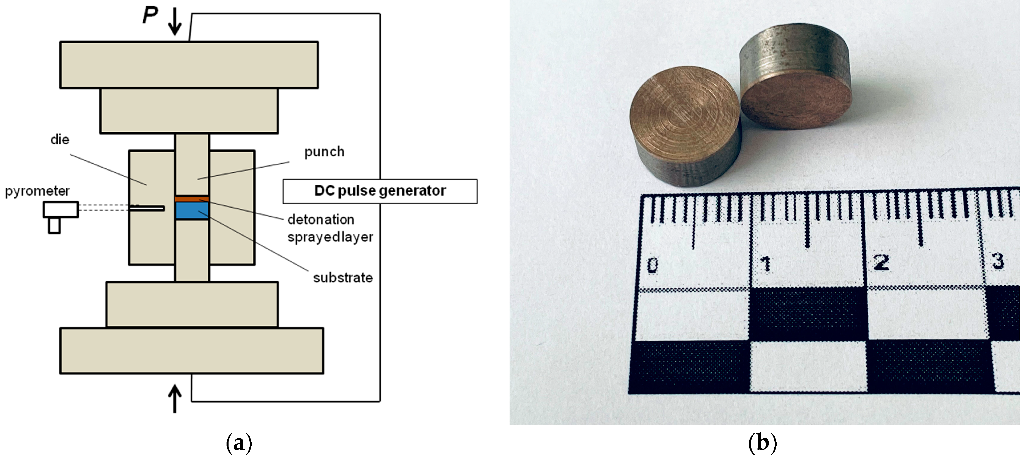
Figure 1. Schematic of the spark plasma sintering (SPS) tooling with a substrate/coating sample (a). General view of the substrate/coating samples machined from the detonation-coated plates (b).
Metals 13 01519 g001
Figure 2. General view (a) and microstructure (b) of the as-sprayed Al-Fe-Co-Ni-Cu coating. Optical images. In (a), the interface with the steel substrate is seen.
Metals 13 01519 g002
Figure 3. General view (a) and microstructure (b) of the as-sprayed Al-Fe-Co-Ni-Cu coating. Back-scattered electron (BSE) imaging mode. In (a), the interface with the steel substrate is seen.
Metals 13 01519 g003
Figure 4. An area of the microstructure of the as-sprayed coating and corresponding elemental maps.
Metals 13 01519 g004
Figure 5. X-ray diffraction patterns of the powder mixture, as-sprayed coating and coatings treated using spark plasma sintering (SPS) at different temperatures.
Metals 13 01519 g005
Figure 6. Microstructure of the coatings treated by SPS at different temperatures: (a) 800 °C, (b) 900 °C, and (c) 1000 °C. BSE imaging mode.
Metals 13 01519 g006
Figure 7. General view (a) and microstructure (b) of the Al-Fe-Co-Ni-Cu coating treated by SPS at 1000 °C. Optical images. In (a), the interface with the steel substrate is shown.
Metals 13 01519 g007
Figure 8. An area of the microstructure of the coating treated by SPS at 800 °C and corresponding elemental maps.
Metals 13 01519 g008
Figure 9. An area of the microstructure of the coating treated by SPS at 1000 °C and corresponding elemental maps.
Metals 13 01519 g009
Table 1. Porosity and Vickers hardness of the as-sprayed Al-Fe-Co-Ni-Cu coatings and coatings subjected to spark plasma sintering (SPS) at different temperatures.
CoatingPorosity, %Vickers Hardness, HV0.3 *Vickers Hardness, HV0.3 **
As-sprayed3320 ± 15315 ± 15
SPS 800 °C<1305 ± 25320 ± 20
SPS 900 °C<1330 ± 30330 ± 20
SPS 1000 °C<1350 ± 20340 ± 15
* Indentation direction normal to the substrate/coating interface; ** indentation direction parallel to the substrate/coating interface.
Disclaimer/Publisher’s Note: The statements, opinions and data contained in all publications are solely those of the individual author(s) and contributor(s) and not of MDPI and/or the editor(s). MDPI and/or the editor(s) disclaim responsibility for any injury to people or property resulting from any ideas, methods, instructions or products referred to in the content.