Abstract
The aim of this study was to investigate the potential application of metal foams in shell-tube recuperators. A356 aluminium foam was cast around the internal and external surfaces of a thin-walled copper tube to enhance heat transfer between separated water streams at different temperatures. The results demonstrated that the aluminium foam drastically increased heat transfer efficiency due to its large volumetric surface area and high thermal conductivity. In the shell-tube foam recuperators, a maximum heat transfer efficiency of 48.1% was observed, compared to only 12.2% for a single copper tube without metal foam. The pressure drop across the external foam increased with the flow rate, from an average value of 1.19 kPa at 1.0 L/min to 7.36 kPa at 3.0 L/min. These findings suggest that metal foams have great potential for use in shell-tube recuperators, which could significantly improve the efficiency of heat transfer in various industrial and engineering applications.
1. Introduction
Metallic foams possess a porous meso-structure that gives rise to exceptional properties, including high specific strength, effective damping, and controlled energy absorption. These distinctive characteristics have led to their extensive consideration for structural applications, particularly within the automotive industry [1]. Moreover, the combination of a high surface-to-volume ratio and excellent thermal conductivity exhibited by the metallic struts makes them highly suitable for enhancing heat transfer in various applications [2,3,4,5]. The integration of metal foams is expected to not only optimize heat transfer but also potentially reduce overall weight while introducing additional functionalities, such as impact attenuation [6]. Chen et al. [7] conducted a study to examine the heat recovery of exhaust gas using a shell-tube heat exchanger equipped with a metal foam baffle. The performance of this design was compared with that of a conventional baffle shell-tube heat exchanger. The investigation primarily involved numerical simulations aimed at evaluating the thermal-hydraulic characteristics of both systems. The findings revealed that the incorporation of metal foam baffles significantly enhanced the area goodness factor, leading to improved heat transfer performance. The area goodness factor quantifies the minimal required frontal area for a fixed pressure drop [8]. To fabricate metal foam-fin heat sinks for efficient cooling of electronic devices, a thermal fused bonding method was employed, wherein aluminium foam was securely attached to an aluminium substrate [9]. Experimental results demonstrated a significant reduction in interfacial thermal contact resistance between the foam and substrate, achieving a remarkable improvement of nearly 19 times compared to traditional heterogeneous epoxy adhesives. Moreover, when compared to commercial fin heat sinks, the foam-fin heat sink exhibited a heat transfer per unit mass that was nearly twice as high. This improvement can be attributed to the enhanced specific surface area of the foam-fin structure, which promotes greater heat dissipation, while also reducing the occurrence of vortex formation in the vicinity of the foam-fin configuration. These findings underscore the potential of metal foam-fin heat sinks as a promising solution for superior thermal management in electronic devices. In [10], an analytical study characterized forced convection in highly porous open-cell metal foam-filled pipes. To this end, the velocity and temperature distribution inside the foam-filled pipes were determined. It was shown that compared to an empty pipe, using the metal foam distinctly enhanced the heat transfer properties of the system. However, this improvement was accompanied by an increased pressure drop. The shape effect of struts on the heat transfer and pressure drop of open-cell metal foams was numerically investigated by Ambrosio et al. [11]. The geometry of three open-cell metal foams with 40 pores per inch and different average porosities was determined using X-ray computed microtomography (XCT). Foam geometry was also modelled using the Lord Kelvin foam model with pore per inch and densities comparable to those of the real foams. A uniform heat flux condition at the solid/fluid boundary was assumed to perform the finite element solutions for all of the models. Numerical simulations yielded the convection heat transfer coefficient and pressure distribution as a function of strut shape parameters. At equal porosity, the maximum convection heat transfer coefficient was observed for convex strut shapes, and the concave-shaped struts maximized pressure drop. In [12], a small plate heat exchanger filled with copper foam, suitable for cooling small-scale electronic components, was studied. This research experimentally investigated the heat transfer coefficient and pressure drop of water flow inside the copper foam-filled plate heat exchanger (PHECF). The research examined the impact of copper foam pore density and water velocity on achieving optimum thermal performance. Under experimental conditions with Reynolds numbers ranging from 1200 to 2000 and copper foam pore densities from 30 to 50 pores per inch (PPI), the results showed that both the heat transfer coefficient and pressure drop increased with higher water velocity and pore density. Notably, compared to a standard plate heat exchanger, the PHECF with pore densities of 30 PPI, 40 PPI, and 50 PPI exhibited enhanced heat transfer coefficients by 20.23%, 29.37%, and 40.28%, respectively. Moreover, the study found that the total pressure drop in the PHECF was predominantly influenced by inertial drag pressure drop. The investigation concluded that the PHECF with a pore density of 50 PPI demonstrated the highest thermal performance, boasting an average thermal performance factor of 1.21. Additionally, practical correlations for the Nusselt number and friction factor of water flow inside the copper foam-filled plate heat exchanger were proposed for real-world applications. In [13], a functionally graded metal foam was considered for the thermal management of a photovoltaic cell. Computational analysis indicates that functional graded porosity can achieve better temperature uniformity. The graded foam improved the overall efficiency and extended the service life of the photovoltaic cell. Open-cell aluminium and copper foams with 20 and 40 pores per inch were computationally analysed in [14]. The metal foam layer was simulated as an attachment to the bottom of a heat exchanger to recover heat from a hot exhaust gas. The results showed that the copper metal foam (with a higher thermal conductivity of the foam struts) provided a higher heat transfer rate compared to the aluminium foam at a similar fluid velocity. In addition, it was shown that the pressure drop in both metal foams increased with the sample height. Lu et al. [15] manufactured rectangular copper foams using the powder metallurgy technique and space holder particles. The heat transfer performance of these copper foams was then experimentally analysed under natural convection. A parametric study of the foam porosity, pore diameter and heating direction of the foams was conducted. In [16], a hybrid heat sink combining aluminium foams and fins was tested as a cooling device for electronic products. A numerical approach was employed to characterise the effect of the fin-to-foam height ratio on the heat removal and pressure drop of this integrated heat sink. Two aluminium foams with similar pore density but different heights (20 and 40 mm) were investigated for their suitability as heat transfer elements in [17]. The height of the aluminium foam did not influence the heat transfer coefficient but increased the pressure drop in the system. Experimental tests were performed using a vertical wind tunnel with symmetrically heated aluminium and copper foams with different thicknesses and porosities by Kamath et al. [18]. The air was passed through the heated foams as a cooling fluid. A heater was sandwiched between two aluminium plates, and the metallic foams were attached to the outer surfaces of these plates. It was shown that the heat transfer coefficient increased with increasing air inlet velocity. Compared to an empty channel (i.e., aluminium plates without foam attachment) it was shown that the metal foams enhanced the heat transfer by a factor of 2.6–3.8. It was also found that the copper foam only enhanced the heat transfer performance by ~4% compared to the aluminium foam. Therefore, the aluminium foam was considered superior due to its reduced cost and improved durability. In [19], open-cell aluminium foams with bimodal pore sizes (1 and 7 mm) were manufactured by infiltrating molten aluminium into a packed mixture of NaCl particles. This procedure is similar to the manufacturing method utilized in the current study. The thermal conductivity of the manufactured aluminium foams was characterised experimentally according to ASTM E-1225-04. The open-cell aluminium foams with 67% coarse and 33% fine pores showed the best combination of high heat transfer capacity and low pressure drop. In previous research by Fiedler et al. [20], copper tubes were surrounded with open-cell ZA27 foam to enhance the heat transfer between two water streams passing through a shell-tube heat exchanger. Overall heat transfer between those water streams was enhanced by up to 71%, which was attributed to the increased surface area of the metal foam compared to exposed copper tubes. An experimental study was conducted to investigate the impact of adding copper foam fins in a double-pipe heat exchanger [21]. The heat exchanger system consisted of two concentric tubes, one made of copper and the other of Perspex. Copper foam fins with a porosity of 40 PPI were employed and positioned at a 30° angle to the tube entrance. These fins were distributed in sections within the annular gap surrounding the inner copper tube, strategically guiding the fluid flow and inducing turbulence within the annular gap. Both parallel and counterflow configurations were examined in this study. A comparison was made between cases with and without the insertion of copper foam fins and between parallel and counterflow modes. The results indicated that as the Reynolds number increased, both the average heat transfer coefficient and the average Nusselt number also increased. The highest values were observed when copper foam fins were inserted, especially in the counterflow mode. An important discovery was that there was no significant increase in pressure drop despite the enhanced heat transfer within the annular gap of the heat exchanger due to the copper foam fins. Additionally, the effectiveness values doubled when copper foam fins were used. Counterflow was identified as the most efficient flow pattern compared to parallel flow. The experimental study demonstrated the advantages of incorporating copper foam fins in a double-pipe heat exchanger. These fins improved heat transfer without causing a notable increase in pressure drop, making them a viable and effective enhancement technique for such heat exchanger systems. A numerical study examined heat transfer from a metal foam-wrapped tube bundle, investigating the impact of key parameters such as free stream velocity, tube pitch, metal foam thickness, and foam characteristics [22]. Metal foam heat exchangers demonstrated superior performance, measured by the area goodness factor, compared to conventional finned-tube designs. At low stream velocities, metal foam heat exchangers exhibited an area goodness factor five times higher than that of finned-tube heat exchangers. Increasing the tube pitch was found to enhance the area goodness factor, while increasing the thickness of the metal foam layer had the opposite effect.
Recent research showed a clear potential to improve heat exchangers by integrating metal foams. Therefore, it is of interest to study novel heat exchanger designs and accurately quantify their performance. In the current research, we used a novel manufacturing method to produce metal foam heat exchanger elements with minimum thermal contact resistances. The heat transfer capacity of this novel heat exchanger was then experimentally studied. A356 aluminium alloy metallic syntactic foams were cast both inside and outside thin-walled copper tubes. To the authors’ knowledge, this is the first attempt to create shell-tube heat exchangers where the metallic foam is directly cast in situ on both sides of the tube, thus minimizing thermal contact resistances. In contrast to [20], the aluminium alloy had a higher thermal conductivity than the previously used ZA27 alloy. More importantly, the addition of metallic foam inside the copper tube was expected to significantly enhance the overall thermal energy transfer between the two separated mass streams.
2. Methodology
2.1. Manufacturing
Thin-walled copper tubes were combined with A356 aluminium foam in single-step counter-gravity infiltration casting. The applied procedure was adapted from [20] by adding metallic foam not only to the outside, but also to the inside of the copper tube (see Figure 1a). In addition, A356 alloy with an increased thermal conductivity was selected instead of the previously used ZA27 alloy for the struts of the metallic foam. The integrated copper tubes had an outer diameter of 19 mm and a wall thickness of 0.9 mm. According to the datasheet of the supplier, the chemical composition of the alloy comprised 92.16 wt% Al, 7.2 wt% Si, 0.4 wt% Mg, 0.1 wt% Fe, and 0.12 wt% Ti [23]. First, a copper tube was centred inside a graphite mould using a flat copper sleeve whose outer diameter matched the internal diameter of the casting mould. This graphite mould had a cylindrical cavity with an outer diameter of 32 mm. After inserting and centring the tube, near-spherical sodium chloride particles with diameters between 2 mm and 2.5 mm were added to fill the cavities within and outside the copper tube (see Figure 1a). The resulting inter-particle contact ensured an optimized interconnected porosity following particle removal. Next, the particles and the copper tube were fixated using a stainless-steel mesh to inhibit motion during casting. Finally, solid A356 aluminium was placed into a graphite crucible before rotating the mould by 180 degrees and inserting it into the same crucible. The resulting assembly was heated inside an electric furnace at 720 °C for 40 min to melt the A356 alloy. The furnace was filled with argon gas to create a protective atmosphere and minimize the oxidation of the graphite mould, crucible, and metallic melt. Directly after removal from the furnace, a 2 kg weight was placed on top of the assembly, introducing a gravitational force that pushed the mould into the crucible. This motion displaced A356 melt into the channels between the sodium chloride particles and the copper tube. A ventilation hole at the top of the mould allowed for the escape of gas and excess melt. Following solidification at atmospheric conditions, the sample was manually removed. The flat surfaces of the cylindrical cast were machined to remove the stainless-steel mesh, increase the open porosity of the surfaces and expose the internal copper tube. The curved cylindrical surfaces were machined to match the inner diameter mm of the Perspex tube of the experimental setup (see Figure 2). Following this, samples were immersed overnight in water at room temperature to dissolve and remove the sodium chloride particles, resulting in an open foam with interconnected pores. One sample with a height mm is shown in Figure 1b.
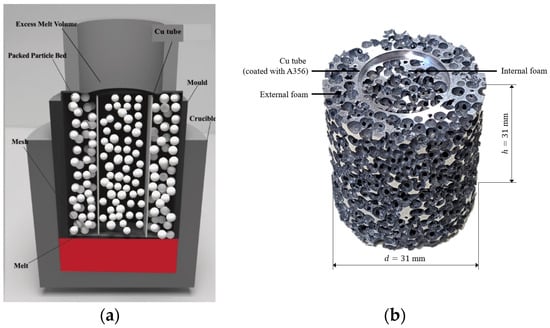
Figure 1.
(a) Schematic of manufacturing process. (b) A356 metal foam heat exchanger element.
In the final step, the diameter of the embedded copper tube was locally decreased to facilitate the interconnection and sealing of stacked foam elements. A total of four A356 foam elements were manufactured for this study. During testing, an approximately 4 mm gap was left between the foam samples to facilitate the external and internal fluid flow (see Figure 2). The porous surfaces of adjacent foam segments differed, which would otherwise result in a very high flow resistance across these interfaces.
For comparative heat transfer measurements, segments of the copper tube were machined to match the overall length of the A356 foam elements (152 mm, including connectors). Comparison of these results then allowed for the quantification of the heat transfer increase due to the metallic foam.
2.2. Experimentation
Figure 3 shows a schematic diagram of the experimental setup. The setup is based on the Armfield HT30XC benchtop service unit and allows the control of two separate mass streams. For the measurements, either four stacked metal foam heat exchanger elements (see Figure 2) or a single copper tube of corresponding length were utilized. Water was heated inside a reservoir to the desired temperature of 60 ± 0.8 °C and circulated using a centrifugal pump. This “hot” stream was configured to flow through the inside of the copper tube to minimize stray heat transfer between the hot liquid and ambient air. A Cynergy3 UF25B ultrasonic flowmeter (accuracy ±5%) controlled the pump to achieve the desired volumetric flow rate . For the “cold” mass stream, tap water (temperature 16.1 ± 0.5 °C) was directed through the outer foam section of the shell-tube heat exchanger before being discharged into a sink. Its volumetric flow rate was controlled using a separate flowmeter and control valve. The direction of the cold flow was opposite to the hot one, meaning the heat exchanger was operated in the more efficient counter-flow configuration.
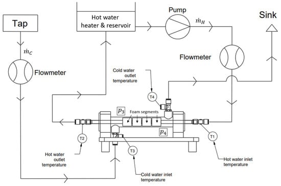
Figure 3.
Schematic of the experimental setup, modified from [20].

Figure 2.
Shell-tube recuperator with four stacked foam elements.
For the quantification of the heat transferred between the mass streams, the four temperatures are measured with type K thermocouples (uncertainty ±0.4 K, supplier RS Components Ltd., Northants, UK). Using the incompressible fluid model, the enthalpy change of each mass stream can be quantified according to , where kJ/kg·K is the heat capacity of liquid water at 300 K [24]. Conducting a first law analysis on each mass stream then yields
and
for the rate of heat transfer from the hot and to the cold mass stream. It should be noted that these equations disregard stray heat transfer. However, due to the thermocouple measurement locations being close to the heat exchanger units and a small temperature gradient between the cool liquid and the ambient air, this simplification was considered acceptable. This assumption was further supported by and exhibiting similar values for all measurements (less than 2.1% deviation). For better readability in the results section, only the average values are presented:
(For – please refer to Figure 3).
Equations (1) and (2) further enable the calculation of the maximum theoretical heat transfer. This is achieved when the exit temperature of the mass stream with the lower volumetric flow rate equals the inlet temperature of the second mass stream. For °C and °C, the corresponding values are listed in Table 1.

Table 1.
Maximum theoretical heat transfer.
The maximum theoretical heat transfer can then be used to define a heat transfer efficiency by normalizing the average measured rate with the maximum possible one, i.e.,
Prior to each measurement sequence, flow meters were carefully calibrated using a 1.0 litre laboratory beaker and a stopwatch to measure the time until full. After ensuring the desired flow rates were met for both mass streams, the target inlet temperature °C of the hot stream was set before waiting for the system to reach thermal equilibrium. Thermal equilibria were identified by the convergence of the outlet temperatures and with respect to time. At this stage, temperatures were recorded for 10 s at a frequency of 10 Hz. The average values of these data were then input into Equations (1) and (2) to calculate the heat transfer rates. Each combination of volumetric flow rates was independently tested three times to probe repeatability of results.
Two RXUP015 sensors enabled the pressure measurement and of the outer mass stream up- and downstream of the foam samples (see red circles in Figure 2). Prior to experimentation, both sensors were calibrated using a Fluke 718 100 G unit. Pressure measurements were conducted for the volumetric flow rates L/min at different water temperatures. The pressure drop was then calculated as the difference between the inlet and outlet pressures. It should be mentioned here that the experimental setup did not allow for the pressure drop measurement of the hot stream.
3. Results and Discussion
Figure 4 shows the heat transferred from the hot (52.2–60.8 °C) to the cold (15.6–16.6 °C) mass stream plotted against the volumetric flow rate of the cold stream. In addition, different flow rates of the hot stream are represented by the drawn (1.0 L/min), dashed (2.0 L/min), and dotted (3.0 L/min) lines. Three different data groups are presented, i.e., shell-tube recuperators with A356 foam elements (yellow), ZA27 foam elements [20] (black), and exposed copper tubes (blue). The error bars in the plot indicate the standard deviation of three independent tests. The standard deviation increased for a high mass flow rate of the cold stream and a low mass flow rate of the hot stream. These combinations resulted in a relatively small temperature change of the cold stream and were thus more sensitive to measurement uncertainty. Analogously, the standard deviation increased for lower mass flow rates of the hot stream. (Analysis of Experimental Uncertainty are provided in Appendix A).
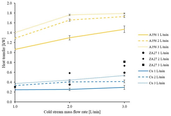
Figure 4.
Average heat transfer between hot and cold mass streams.
Comparing sample groups, a significant heat transfer enhancement was found for the A356 foam heat exchangers. For the maximum flow rates, the measured heat transfer was 0.53 kW for the copper tube, 0.81 kW for ZA27 foam, and 1.79 kW for Al356 foam elements. This corresponded to a 235% increase in the heat transfer for A356 foam elements relative to the exposed copper tube.
For further analysis, a thermal energy flow model illustrated in Figure 5 was proposed. Thermal energy enters the heat exchanger with the hot liquid and is first transferred to the inner metallic foam. This convective heat transfer increases for larger temperature differences between the fluid and the foam as well as for increased volumetric flow rates. In all experiments, the inlet temperatures of the hot stream (52.2–60.8 °C) and cold stream (15.6–16.6 °C) were kept nearly constant, resulting in an overall temperature difference of about 44 °C. Hence, changes in the convective thermal resistance were predominantly associated with variation of the volumetric flow rate . Next, the thermal energy was conducted from the inner foam and through the copper tube. Due to the high thermal conductivity of the A356 matrix ( W/m·K) and copper tube ( W/m·K) [25], the conductive thermal resistance was relatively low. Importantly, there was no significant thermal contact resistance between the foams and the tube, as the A356 melt solidified in direct contact with the copper tube following casting. The good wettability of the copper tube is apparent in Figure 1, where a thin layer of A356 covers the copper tube. This also resulted in a low thermal resistance for the conductive heat transfer from the copper tube into the outer foam. From there, the thermal energy was transferred into the cold liquid via convective heat transfer. Analogous to the hot stream, this convective resistance could be decreased by increasing the volumetric flow rate . Stray heat transfer occurred in the form of thermal conduction along the copper tube and through the Perspex tube (thermal conductivity 0.187–0.216 W/m·K) [26]. Both losses were considered small compared to the internal heat transfer between hot and cold streams and were, therefore, disregarded. This simplification was supported by similar values of and , indicating that little energy was lost to the surroundings. For the resulting series connection, the overall thermal resistance was the sum of the convective and conductive thermal resistances, i.e., .
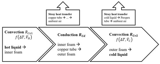
Figure 5.
Thermal energy flow model.
Comparing the A356 foam and ZA27 foam heat exchanger elements in Figure 4, a distinctly better performance of the aluminium samples was observed. This could in part be explained by the increased thermal conductivity of the A356 alloy ( W/m·K) compared to ZA27 ( W/m·K [26]), resulting in a slightly decreased conductive resistance . However, the main difference was that the A356 heat exchanger elements contained foam elements outside as well as inside the copper tube. In contrast, the ZA27 samples only held foam outside the hollow tube [18]. This resulted in a high convective resistance that significantly decreased the performance of the ZA27 heat exchangers. Figuratively, the convective heat transfer at the inner tube surface created a bottleneck for the thermal energy flow and also limited performance increases due to the external foam. As expected, the lowest heat transfer was observed for the exposed copper tube recuperator (blue lines). In this case, both convective resistances were high, resulting in comparably poor heat transfer performance.
For all tests, the transferred heat increased with the volumetric flow rate of the cold stream (see Figure 4, left to right) and volumetric flow rate of the hot stream (bottom to top). This indicated that the convective heat transfer presented a significant resistance to the thermal energy flow. However, the sensitivity of the heat transfer to the volumetric flow rate differed. For A356 foam and a hot stream flow rate of 1.0 L/min (solid yellow line), an approximately linear increase was found with increasing cold mass flow rate. It could be concluded that within the considered range, the heat transfer was limited by the external cold mass flow. However, for hot stream flow rates of 2.0 and 3.0 L/min (dashed and dotted yellow lines), a comparatively smaller change was found for an increase in the cold stream flow rate from 2.0 to 3.0 L/min. In this case, the heat transfer from the hot liquid to the internal foam likely approached its maximum and, therefore, a further increase in the cold fluid flow rate had limited effect. This theory was further supported by the fact that the 2.0 and 3.0 L/min (hot stream) foam heat exchanger lines were closer to each other compared to the 1.0 and 2.0 L/min lines. For the effective design and operation of heat exchangers, a balanced solution must, therefore, be found, where the overall performance is not limited by a single high thermal resistance.
In Table 2, the heat transfer efficiency has been calculated according to Equation (4). For any given combination of hot and cold stream volumetric flow rates, A356 foam achieves higher efficiencies compared to the copper tube. This is expected, as Figure 4 clearly indicates the heat transfer enhancement due to the A356 foam. The highest observed efficiency was obtained for L/min and L/min. In this case 48.1% of the maximum theoretical heat transfer was reached. It is interesting to see that the A356 efficiency matrix is approximately symmetrical, i.e., an increase in the cold or hot mass stream flow rate has a similar effect.
Table 2.
Heat transfer efficiency .
Pressure drop measurements were conducted for the external mass stream, and the results are summarized in Table 3. No clear correlation between fluid temperature and pressure drop was observed, and variations were attributed to experimental uncertainty. However, the data clearly indicated that the pressure drop rapidly increased with the volumetric flow rate: tripling the volumetric flow rate from 1.0 to 3.0 L/min resulted in a 5.76-fold increase in the pressure drop.
Table 3.
Pressure drop of the outer mass stream.
An optimum heat exchanger combines a high rate of heat transfer with minimum pressure drop. In Figure 6, the heat transfer is plotted versus the average pressure drop of the cold stream, and good performance is thus indicated by data points located towards the top left of the graph. Not surprisingly, the performance increased with the flow rate of the hot stream. However, the measurements did not consider the pressure drop of the hot stream, which, of course, increased with the increasing hot stream flow rate. Considering a constant hot stream flow rate, the heat transfer increased with higher cold stream flow rates. However, Figure 6 clearly indicates that any additional heat transfer is at the expense of a distinctly increased pressure drop. In this study, the highest ratio between heat transfer and pressure drop was thus found for the volumetric flow rate L/min.
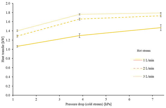
Figure 6.
Average heat transfer plotted versus pressure drop.
Table 4 provides the numerical values for heat transfer, which have been normalized by the pressure drop of the cold stream. As previously discussed, the optimal values were obtained when the cold stream flow rate was at its lowest, specifically at 1.0 L/min. This flow rate coincided with the minimum observed pressure drop of 1.19 kPa. However, as the cold stream flow rate increased beyond this optimum point, the subsequent rise in thermal energy transfer failed to keep up with the significant increase in pressure drop. This led to a less efficient heat transfer process.
Table 4.
The ratio of heat transfer to pressure drop [W/Pa].
4. Conclusions
A356 metallic syntactic foam was successfully combined with thin-walled copper tubes to create compact heat transfer elements for application inside shell-tube recuperators. Compared to a single exposed copper tube (maximum 0.53 kW), maximum heat transfer was enhanced to 1.79 kW. In addition, heat transfer performance distinctly exceeded the results of a previous study using ZA27 foam elements (maximum 0.81 kW). A likely explanation for this improved performance is the usage of metallic foam outside as well as inside the copper tube, resulting in decreased convective heat transfer resistance. Pressure drop measurements indicated moderate losses of 1.19 kPa at the lowest considered volumetric flow rate of 1.0 L/min. However, the pressure drop rapidly increased at higher flow rates, i.e., 7.36 kPa at 3.0 L/min. At the same time, an increase in the volumetric flow rate resulted in relatively small heat transfer gains. Overall, the integration of A356 foam for heat transfer enhancement has been shown to be suitable for the development of compact heat exchangers with high rates of heat transfer.
Author Contributions
Conceptualization, T.F. and N.M.; methodology, T.F. and N.M; formal analysis, N.M.; investigation, N.M.; resources, T.F.; data curation, N.M.; writing—original draft preparation, T.F.; writing—review and editing, T.F. and N.M; visualization, T.F. and N.M; supervision, T.F.; project administration, T.F.; funding acquisition, T.F. All authors have read and agreed to the published version of the manuscript.
Funding
This research received no external funding.
Data Availability Statement
The data of this research can be obtained by contacting the corresponding author.
Acknowledgments
The authors want to acknowledge the valuable contribution of Harley Johns, who conducted extensive experimentation in the scope of his Honours Project that lead to the measurements presented in this paper. We further want to acknowledge the comprehensive expertise and support of the technical staff at the University of Newcastle, in particular Mitch Gibbs.
Conflicts of Interest
The authors declare no conflict of interest.
Appendix A. Analysis of Experimental Uncertainty
This appendix presents the analysis of the experimental uncertainty for the rate of heat transfer. Sensor information is summarized in Table A1 below.
Table A1.
Sensor information.
Table A1.
Sensor information.
| Property | Sensor Type | Uncertainty |
|---|---|---|
| Temperature | Type K thermocouple | ±0.4 K |
| Mass flow | Cynergy3 UF25B | ±5% |
The heat transfer rates are calculated using a formula of the shape
Using linear approximation, the uncertainty for the heat transfer rate can be estimated using
Evaluation of the partial differentials yields
and the relative deviation is obtained using
For the minimum temperature difference of all tests K, we finally obtain
References
- García-Moreno, F. Commercial Applications of Metal Foams: Their Properties and Production. Materials 2016, 9, 85. [Google Scholar] [CrossRef] [PubMed]
- Iasiello, M.; Bianco, N.; Chiu, W.K.; Naso, V. Anisotropic convective heat transfer in open-cell metal foams: Assessment and correlations. Int. J. Heat Mass Transf. 2020, 154, 119682. [Google Scholar] [CrossRef]
- Jeng, T.-M.; Tzeng, S.-C.; Xu, R. Experimental study of heat transfer characteristics in a 180-deg round turned channel with discrete aluminum-foam blocks. Int. J. Heat Mass Transf. 2014, 71, 133–141. [Google Scholar] [CrossRef]
- Nawaz, K.; Bock, J.; Jacobi, A.M. Thermal-hydraulic performance of metal foam heat exchangers under dry operating conditions. Appl. Therm. Eng. 2017, 119, 222–232. [Google Scholar] [CrossRef]
- Aljubury, I.M.A.; Saihood, R.G.; Farhan, A.A. Experimental study on thermo-hydraulic performance of metal foam twisted tape in a double pipe heat exchanger. Heat Transf. 2022, 51, 7910–7928. [Google Scholar] [CrossRef]
- Tamkhade, P.K.; Lande, R.D.; Gurav, R.B.; Lele, M.M. Investigations on tube in tube metal foam heat exchanger. Mater. Today Proc. 2022, 72, 951–957. [Google Scholar] [CrossRef]
- Chen, T.; Shu, G.; Tian, H.; Zhao, T.; Zhang, H.; Zhang, Z. Performance evaluation of metal-foam baffle exhaust heat exchanger for waste heat recovery. Appl. Energy 2020, 266, 114875. [Google Scholar] [CrossRef]
- Sahiti, N.; Durst, F.; Dewan, A. Strategy for selection of elements for heat transfer enhancement. Int. J. Heat Mass Transf. 2006, 49, 3392–3400. [Google Scholar] [CrossRef]
- Samudre, P.; Kailas, S.V. Thermal performance enhancement in open-pore metal foam and foam-fin heat sinks for electronics cooling. Appl. Therm. Eng. 2022, 205, 117885. [Google Scholar] [CrossRef]
- Lu, W.; Zhao, C.; Tassou, S. Thermal analysis on metal-foam filled heat exchangers. Part I: Metal-foam filled pipes. Int. J. Heat Mass Transf. 2006, 49, 2751–2761. [Google Scholar] [CrossRef]
- Ambrosio, G.; Bianco, N.; Chiu, W.K.; Iasiello, M.; Naso, V.; Oliviero, M. The effect of open-cell metal foams strut shape on convection heat transfer and pressure drop. Appl. Therm. Eng. 2016, 103, 333–343. [Google Scholar] [CrossRef]
- Nilpueng, K.; Asirvatham, L.G.; Dalkılıç, A.S.; Mahian, O.; Ahn, H.S.; Wongwises, S. Heat transfer and fluid flow characteristics in a plate heat exchanger filled with copper foam. Heat Mass Transf. 2020, 56, 3261–3271. [Google Scholar] [CrossRef]
- Tan, W.C.; Saw, L.H.; Thiam, H.S.; Garg, A.; Pambudi, N.A. Numerical study of the geometrically graded metal foam for concentrated photovoltaic solar cell cooling. Energy Procedia 2019, 158, 761–766. [Google Scholar] [CrossRef]
- Kotresha, B.; Gnanasekaran, N. Numerical Simulations of Fluid Flow and Heat Transfer through Aluminum and Copper Metal Foam Heat Exchanger—A Comparative Study. Heat Transf. Eng. 2018, 41, 637–649. [Google Scholar] [CrossRef]
- Lu, X.; Zhang, Y.; Xiao, S.; Zhao, Y.; Li, J.; Zhou, J.; Ouyang, Q. Effect of structural characteristics on the natural convective heat transfer performance of copper foam. Appl. Therm. Eng. 2022, 204, 118031. [Google Scholar] [CrossRef]
- Şahin, Y.S.; Toprak, B.I.; Solmaz, I.; Bayer, O. Investigation of flow and heat transfer behavior of integrated pin fin-aluminum foam heat sink. Appl. Therm. Eng. 2023, 219, 119504. [Google Scholar] [CrossRef]
- Mancin, S.; Zilio, C.; Rossetto, L.; Cavallini, A. Foam height effects on heat transfer performance of 20 ppi aluminum foams. Appl. Therm. Eng. 2012, 49, 55–60. [Google Scholar] [CrossRef]
- Kamath, P.M.; Balaji, C.; Venkateshan, S. Convection heat transfer from aluminium and copper foams in a vertical channel—An experimental study. Int. J. Therm. Sci. 2013, 64, 1–10. [Google Scholar] [CrossRef]
- Durmus, F.; Maiorano, L.; Molina, J. Open-cell aluminum foams with bimodal pore size distributions for emerging thermal management applications. Int. J. Heat Mass Transf. 2022, 191, 122852. [Google Scholar] [CrossRef]
- Fiedler, T.; Moore, R.; Movahedi, N. Manufacturing and Characterization of Tube-Filled ZA27 Metal Foam Heat Exchangers. Metals 2021, 11, 1277. [Google Scholar] [CrossRef]
- Hamzah, J.A.; Nima, M.A. Experimental Study of Heat Transfer Enhancement in Double-Pipe Heat Exchanger Integrated with Metal Foam Fins. Arab. J. Sci. Eng. 2020, 45, 5153–5167. [Google Scholar] [CrossRef]
- Odabaee, M.; Hooman, K. Metal foam heat exchangers for heat transfer augmentation from a tube bank. Appl. Therm. Eng. 2012, 36, 456–463. [Google Scholar] [CrossRef]
- Al-Sahlani, K.; Broxtermann, S.; Lell, D.; Fiedler, T. Effects of particle size on the microstructure and mechanical properties of expanded glass-metal syntactic foams. Mater. Sci. Eng. A 2018, 728, 80–87. [Google Scholar] [CrossRef]
- Moran, M.J.; Shapiro, H.N.; Boettner, D.D.; Bailey, M.B. Fundamentals of Engineering Thermodynamics, 9th ed.; Wiley: Hoboken, NJ, USA, 2019. [Google Scholar]
- ASM International Handbook Committee. Metals Handbook, Vol. 2—Properties and Selection: Nonferrous Alloys and Special-Purpose Materials, 10th ed.; ASM International: Novelty, OH, USA, 1990. [Google Scholar]
- Electronics Cooling—Design, Materials, Compounds, Adhesives, Substrates, Number 2, Technical Data, Volume 7.
Disclaimer/Publisher’s Note: The statements, opinions and data contained in all publications are solely those of the individual author(s) and contributor(s) and not of MDPI and/or the editor(s). MDPI and/or the editor(s) disclaim responsibility for any injury to people or property resulting from any ideas, methods, instructions or products referred to in the content. |
© 2023 by the authors. Licensee MDPI, Basel, Switzerland. This article is an open access article distributed under the terms and conditions of the Creative Commons Attribution (CC BY) license (https://creativecommons.org/licenses/by/4.0/).