Abstract
This study examined the solidification features and wear of AlSi10Mg(-Ni) alloy samples generated under various conditions. Additions were varied from 0 to 3 wt% Ni while maintaining Si and Mg contents. All samples were directionally solidified (DS) and laser treated using surface laser remelting (LSR). Both DS and LSR samples were characterized by a number of methods, including the following: thermal analysis, optical microscopy, stereomicroscopy, scanning electron microscopy (SEM), energy dispersive X-ray spectroscopy (EDS), wear tests, and Vickers hardness. Ranges for cooling rates, dendritic spacing and hardness, respectively, were from 0.4 to 13.3 K/s, from 77 to 388 μm, from 71 to 93 HV for the DS samples and from 4.3 × 10⁴ to 8.7 × 10⁴ K/s, from 1.0 to 2.0 μm, and from 114 to 143 HV for the LSR (100 J/mm2). The solidification kinetics had a large impact on the solidified samples, allowing a representative range of microstructures and morphologies to be examined in terms of wear. The 1% Ni alloy had the highest wear resistance among all the DS samples under slow cooling and the short-term wear test (10 min/0.5 N), while the LSR samples showed similar wear resistances regardless of the Ni content. The uniform dispersions of Si and Al3Ni forming intercellular dense walls at the top of the laser molten pool together with their rod-like morphologies and reduced dendrite spacing of less than 2 μm, improved bonding with the matrix, resulting in higher and more consistent wear resistance of the laser treated surfaces.
1. Introduction
Despite their many uses and adaptability, cast Al-Si alloys have higher demands for improved temperature and wear-resistance capabilities as a result of the advancement of vehicle lightweighting and fuel efficiency [1,2]. Hypoeutectic Al-Si casting alloys are frequently used in automotive parts like brake rotors, pistons, and blocks due to their high strength-to-weight ratio, acceptable mechanical properties, and low thermal expansion, among other features [3]. Further development perspectives of these alloys demonstrate a critical need for mechanical and wear property improvements [4].
One of these alloys of interest is the AlSi10Mg alloy. It is considered an extremely versatile material, being explored in a wide range of casting techniques such as additive manufacturing, die casting, and permanent mold casting [5,6,7,8]. Among the most relevant applications are machine and vehicle construction, transportation, and the food industry. Although some of the techniques mentioned above allow for rapid cooling, the alloy microstructure may contain relatively coarse and needle-shaped eutectic Si particles. Because needle-shaped Si crystals are known to be harmful to the mechanical properties, they must be modified to avoid such effects [9,10]. In order to improve the alloy, the major strategies are related to issues such as change of chemical composition, control of phase morphologies, and dispersion of secondary phases in the α-Al matrix, so that component performance can be optimized considering either low or high temperature applications.
One of the strategies for improving mechanical and tribological properties is to incorporate alloying elements (such as Mn, Fe, Cu, and Ni) so that the size, morphology, and distribution of the secondary phases could be improved. Abouei et al. [11], for instance, added Mn to a Fe-containing Al-Si alloy in order to transition from needle-like α-Al5FeSi phase to modified α-Al15(Fe, Mn)3Si2 phase. This modified morphology has been shown to reduce the negative effects of iron-rich intermetallic compounds and has resulted in improved wear resistance. This is because bonding of the modified α-phase with the α-Al matrix is improved, with less possibility remaining of subsurface microcracking during sliding action.
Despite the significant progress made in studying the impact of various modifying Al-Si alloy compositions on the structure and mechanical properties, there is a notable lack of data regarding modification by super- and nano-dispersed particles. Zykova et al. [12] explored the effects of adding 0.01–0.5 mass% W nanopowder to an Al-12%Si alloy. Their findings indicate that the optimal addition is 0.1 mass% of W, leading to the uniform distribution of eutectic (α-Al + Si), a 1.5-time reduction in the size of eutectic Si plates, a transformation of coarse plates (coarse plate-like or acicular) into a fine fibrous structure, and a remarkable enhancement of mechanical properties by 16–20%. Another work [13] examined the influence of in situ χ-Al2O3 particles on the morphology and size of primary and eutectic Si phases in a hypereutectic Al-20%Si alloy. The microstructural analyses revealed that the presence of in situ Al2O3 particles leads to a substantial refinement of primary Si crystals, transforming them from coarse polygonal and star-like shapes to fine block-like shapes with smooth edges and corners.
As already mentioned, wear resistance, in addition to the mechanical properties, is an important index for near eutectic Al-Si casting alloys due to the current use in the manufacture of friction parts. Wear behavior of Al-Si, Al-Si-Fe, and Al-Si-Cu cast alloys has been studied in various investigations. Few studies, however, have looked at the effect of Ni additions on the damage and wear properties of Al-Si-Mg alloys, particularly bringing a vinculation between the wear behavior and the different microstructure aspects such as varying the dendritic/cellular length-scale microstructures, the phase morphologies, and the phase fractions, among others.
The role of Ni in improving the mechanical properties of Al and Al-Si alloys has been widely accepted due to the formation of Ni-rich phases [1,14,15,16,17,18,19]. Li et al. [14] demonstrated that both the AlSiFe and the Al3CuNi phases are strengthening phases that enclosed the α-Al matrix, reinforcing the Al-rich matrix. According to Zuo et al. [1], the ultimate tensile strength and yield tensile strength of Al-Si-Cu-Ni alloys increased as the volume fraction of the Al3CuNi phase increased, this phase being stable at 350 °C.
Thermal stability of Al3Ni intermetallics has been demonstrated up to 450 °C [19,20], whereas Cu and Mg additions (typically alloyed in Al-Si alloys) are expected to produce thermally unstable intermetallics above 200 °C [21]. This stability encourages the use of Ni-modified alloys for high temperature applications. In addition to this benefit, it has also been reported that these Ni-bearing intermetallics inhibit the growth of eutectic Si needles and form primary Si particles, which frequently accompany the improvement of properties in Al-Si based alloys [22]. The Al3Ni is considered to be one of the most prominent intermetallics based on Al due to its superior hardness (841 HV) and strength (2160 MPa) [23].
Savaskan et al. [24] studied the wear of one ternary Al-40Zn-3Cu and six quaternary Al-40Zn-3Cu-(0.5-3)Ni permanent mold cast alloys. The wear volume increased for content samples from 0 to 0.5 Ni and then decreased from 0.5 Ni to 3.0 Ni. The alloy wear surfaces revealed smearing and scratches. Moreover, smearing was found to be the most common wear mechanism for these alloys. Savaskan et al. [24] concluded that shape, size, and distribution of the Al3Ni intermetallic phase controlled the wear resistance.
Liu at al. [25] investigated the effect of Ni content (0 to 3% Ni) on the wear behavior of Al-13Si-3Cu-1Mg-xNi-0.6Fe-0.6Mn alloys. A 3D network structure was observed being formed by α-Al matrix, eutectic Si, Q, Ni-rich, and Al15(Mn, Fe)3Si2 phases, with the 2% Ni alloy resulting in the best wear resistance. Excessive coarse Al3Ni phase fracture and debonding reduced the wear resistance and ductility of the 3Ni-containing alloy. The main mechanisms of the tested alloys were abrasive, delamination, and oxidative wear.
To investigate wear properties, different concentrations of Ni (from 0.8% to 3.5%) were doped into a commercial eutectic Al-Si alloy (Al-12.7Si-3Cu-0.7Mg-0.1Fe) by Mirzaee-Moghadam et al. [26]. The highest wear resistance was found in the samples containing 2–2.6% Ni, owing to uniform dispersion, skeleton-type morphology of Ni-rich intermetallics, and better bonding with the Al-rich matrix.
The present study introduces several novel aspects, including a comprehensive investigation of the influence of varying Ni content on the microstructure. Additionally, it sheds light on the effects of cooling rates on the dendritic microstructure scale. Moreover, the research significantly expands the potential of the laser surface remelting (LSR) process to enhance wear resistance in Al alloys, providing valuable insights into its practical applications for wear improvement. The findings contribute to a deeper understanding of alloy behavior and microstructural development, opening up new possibilities for optimizing materials with improved wear performance in diverse engineering applications.
This study aims to examine how adding Ni (1 to 3 wt%) and adjusting dendritic length-scales in AlSi10Mg(-Ni) alloy samples, processed through slow or rapid solidification, impacts the second phase morphologies and dry wear behavior. The goal was to identify the best alloy composition and microstructure arrangements that enhance wear resistance.
2. Materials and Methods
Two solidification methods were used to produce the samples. First, each alloy was subjected to a DS system under unsteady-state heat flow regime. Second, DS transverse samples of each alloy related to a single solidification rate of 0.7 °C/s were used for the LSR tests.
The AlSi10Mg(-Ni) alloys were initially fabricated in an induction furnace (Inductotherm, VIP Power-Trak model, Rancocas, NJ, USA) with a 50 kW power source and a frequency of 3.2 kHz. The raw materials used were commercially pure Al, Mg, Si, and Ni elements, ensuring charge balance. To avoid trapping gases during solidification, both alloys underwent a 2 min degassing process before being poured.
The AlSi10Mg (0Ni), AlSi10Mg-1Ni (1Ni), AlSi10Mg-2Ni (2Ni), and AlSi10Mg-3Ni (3Ni) alloys were poured into cylindrical molds internally coated with a refractory layer to prevent radial heat losses during DS. K-type thermocouples were positioned in relation to the length of the casting from the water-cooled bottom section in order to collect temperature data as a function of time. Water flow was initiated against the exterior surface of the mold bottom part when the molten material had attained 5% above the liquidus temperature, facilitating upward directional solidification.
After producing the castings and registering the cooling curves, several samples were sectioned. The samples were sanded and polished. After 0.5 percent HF etching for 10–20 s, the resulting microstructures showed. Following image acquisition with an optical microscope (Olympus GX41, Tokyo, Japan), the dendritic spacings were measured using adequate techniques [27], taking the optical image transverse sections into account. The cooling rates of the DS samples were also assessed through analytical techniques of determination, using the experimental temperature x time data [28,29,30]. Eight positions (P1…P8) were examined along each casting. The cooling rate data were linked to the dendritic spacing so that scaling growth relationships could be established. As a clearer form of presentation of the results, some of the plots are shown in terms of P1, P3, and P8 as representative of different conditions during DS. These positions refer to 5, 15, and 90 mm from the metal/mold interface.
Plates with 21 mm × 28.5 mm × 3.1 mm removed from the casting were ground with SiC paper of increasing fineness (#180, #400, #800, #1200, and #1500 grit), blasted with 80 µm steel shot (4.5 kgf/cm2), cleaned with alcohol, and then irradiated with Aurora Labs® S-Titanium Pro CO2 laser system (with wavelength of 10.6 µm) while being shielded by high purity Ar gas. The laser parameters were adjusted to attain energy densities of 100 and 400 J/mm2, with scanning speeds of 5 and 20 mm/s, power of 300 W, and a spot size of 150 µm. The overlapping rate during laser processing was 70%. After measuring the dendritic spacing values for the bottom, center, and top of the treated pools, it was possible to extrapolate the already registered DS growth data to determine the average cooling rates that characterize the LSR surfaces.
Cross-sections of the laser-treated samples were subjected to Vickers microhardness tests with a test load of 25 gf and a dwell time of 15 s. Hardness profiles were also determined for the DS samples, with a load of 2000 gf by using a HMVG20ST Shimadzu tester (Shimadzu, Kyoto, Japan). All four alloys underwent dry micro-adhesive (ball crater) wear tests [31,32] along with a wide range of samples corresponding to a very broad range of dendritic spacing, from 1.0 µm to 388 µm. During the tests, wear craters were created by rotating a hard tool steel ball (AISI 52,100 steel, diameter 25.4 mm) against the surface for periods of i. 60 min with 1N, and ii. 10 min with 0.5 N. Cruz et al. [30] also subjected this level to low loads in their study. The crater’s size typically increased proportionately with the test duration while 250 rpm was the ball sliding speed maintained for all tests. The dimensions related to the wear craters were measured using a stereomicroscope and confirmed with a confocal microscope (Olympus LEXT OLS4000, Tokyo, Japan). It is worth noting that measurements of hardness, wear, and dendritic spacing were carried out with statistical rigor, with significant sampling for each condition. The wear volume (V) was calculated using the rotating ball radius (R) and experimental crater diameters (d), i.e., V = (π × d4)/(64 × R), following the procedure described in the literature [30]. The dendrite arm spacing was determined by averaging the distances between the centers of consecutive branches [33]. To achieve this, image processing tools were utilized, and approximately 40 readings were taken for each examined condition, encompassing both LSR and DS samples.
Both DS samples and LSR coatings were examined through SEM microscopy. Higher magnification images, identification of the generated phases, and analysis of wear damage were performed using scanning electron microscopy (SEM) (Philips XL 30 FEG, Eindhoven, The Netherlands and Thermo Fisher Scientific, Helios G4 UX Dual Beam, Waltham, MA, USA). To make it easier to examine the phase morphologies, a 3 min deep etching with HCl was carried out. The molten pool structures’ tops received extra attention because wear damage was mainly more prevalent there.
Figure 1 shows all information regarding the experimental procedures used as well as those supporting the sample characterizations.
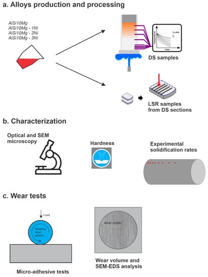
Figure 1.
Flowchart representing the whole scheme employed for: (a) alloys production and processing; (b) characterization, and (c) wear tests of the DS and LSR AlSi10Mg(-Ni) alloys.
3. Results and Discussions
3.1. Sample Solidification Data: DS and LSR
The data shown in the maps in Figure 2 and Figure 3 clearly show the effects of cooling rate on the final microstructure, and the results could be extended to different casting processes, such as sand casting, permanent mold casting, pressure casting, as well as rapid solidification operations. The DS data on the left side of the plots revealed that as the solidified layer increased (from P1 to P8), the solidification cooling rate decreased due to increased thermal resistance for heat removal during solidification. There is no discernible pattern associated with the Ni effect on the DS cooling rate data. However, it is clear that P8-sample cooling rates are related to sand casting, whereas P1-sample values in Figure 2 are similar to those typically observed in permanent molds, thus becoming very representative samples for testing tangible industrial processing conditions.
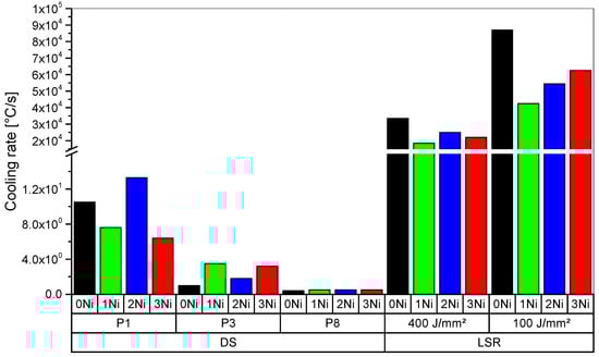
Figure 2.
Experimental and estimated cooling rate data along both DS and LSR samples.
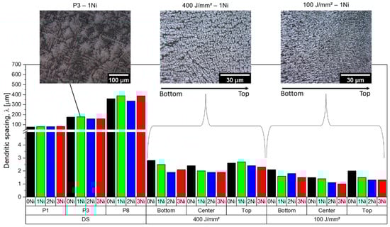
Figure 3.
Measured dendritic spacing profiles in both DS and LSR samples.
Through the dendritic spacing measurements, the dendritic-scale can be reversed as cooling rates increase, as seen in Figure 3. As the cooling rate decreased, the spacing increased. The DS power relations were found to be consistent with those reported in the literature by using the entire P1…P8 data set, which included eight points monitored here [34,35]. Examining each cooling rate level during DS in Figure 2 and taking into account the Ni contents added, it appears that dendritic spacing (Figure 3) may not be significantly impacted by Ni content. To extend this behavior, however, discrete analysis and comparison of the dendritic spacing of the AlSi10Mg-3Ni with that shown by Kakitani et al. [36] for an alloy with a higher Ni content (i.e., Al-11Si-5Ni) may be viable. Dendritic spacing increased with higher Ni content (>3 Ni [32]), reaching a value of 130 µm for a cooling rate of approximately 6.0 K/s as opposed to 82 µm for the same cooling rate for the AlSi10Mg-3Ni alloy. Liquid Ni has a higher density than Al. As a result, when it is rejected at the solidification interface, it flows downwards in the liquid interdendritic channels located between the major dendritic arms. It seems that higher Ni content, such as 5% Ni, impacts primary trunk growth by increasing the spacing due to the lateral extended growth of secondary stems in between.
The estimated LSR cooling rates are the averages of those estimated in the bottom and center of each alloy’s molten pool over the two energy density conditions shown in Figure 2 (right side data). The cooling rates were lower for the 400 J/mm2 samples due to the higher energy being released during solidification. Overall, the low scanning speeds applied in the present investigation allow for smaller cooling rates (<9 × 10⁴ K/s) when compared to those characterizing SLM (selective laser melting) cooling rates for AlSi10Mg alloys. For example, during SLM of the AlSi10Mg alloy at a very high laser speed of 1500 mm/s, Liu et al. [37] estimated top surface cooling rates of approximately 106 °C/s. Kurz and Fisher [38] reported extremely high solidification cooling rates during LSR of Al alloys (ranging from 104 to 107 °C/s).
Even with relatively low LSR cooling rates, the structure obtained had much smaller dendritic spacing than the DS samples. The dendritic/cellular spacings at the top surface of the molten pool of the 100 J/mm2-samples were 1.0–2.0 µm, while the spacings were measured between 2.3–2.7 µm for the laser energy density of 400 J/mm2. Such refined dendritic microstructures generated suitable contrast surfaces for wear testing evaluation of extreme microstructural features.
Hardness values increased clearly with decreasing λ (i.e., increasing λ−1/2 in Figure 4), and also with increasing Ni content. The 4× different laser energy densities used for the three Ni-content alloys did not result in a significant difference in hardness. This proves that the laser treatment was successful in refining the microstructure and enhancing the surface mechanical properties of the AlSi10Mg(-Ni) alloys.
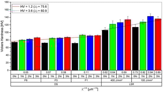
Figure 4.
Hardness profiles obtained for the four tested alloys considering both DS and LSR samples.
3.2. Wear and Damage Analysis
Experimental relationships between the wear volume (V) and the inverse square root λ, as shown in Figure 5, enabled a comparison of the tested alloys while also taking the dendritic microstructure scale indicator λ into account. Both LSR and DS samples had this interrelation performed under two wear conditions. Wear volumes in Figure 5a are approximately 10 times higher than those seen in Figure 5b.
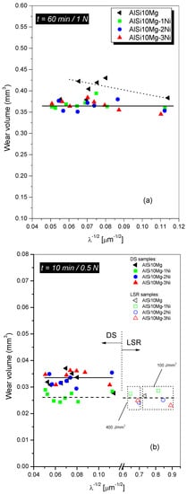
Figure 5.
Wear volume data: (a) the DS samples for 60 min applying 1 N (long-term); and (b) the DS and LSR samples for 10 min and 0.5 N (short-term).
By comparing the DS alloy samples subjected to more rigorous surface damage requirements (60 min/1 N), it is observed that the Ni-modified alloys had their resistance increased in comparison with the ternary AlSi10Mg alloy. In this loading configuration, the worn surface becomes much plastically deformed, increasing the surface’s damage dependence on mechanical properties. Alloys containing Ni have a higher hardness and, consequently, become more resistant under such wear conditions. In contrast, the λ−1/2 scale endures no expressive variations of the wear volume. This is because the DS sample microstructures are formed by very coarse Si and Al3Ni particles, as shown in Figure 6. Despite changing Ni concentration, the absence of refinement of these structures during slow solidification had no effect on wear resistance, as can be seen in Figure 5a under further long wear tests.
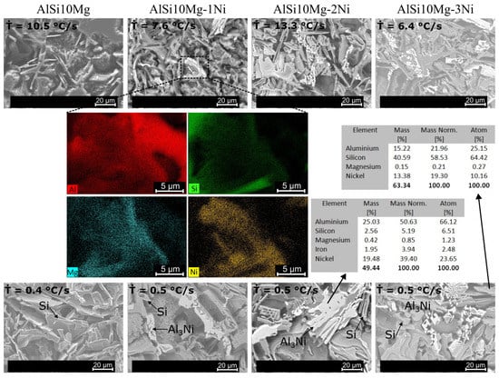
Figure 6.
SEM images and EDS data of the DS AlSi10Mg(-Ni) alloy samples before the wear tests.
The hardness of the Ni-modified alloys, for example, considering P1-samples, is approximately 93 HV, whereas the ternary alloy (without Ni) has a hardness of 71 HV. As a result, the ternary DS alloy had slightly reduced wear resistance, as can be seen in Figure 5a.
Cruz and coauthors [30] used the same ball crater test to investigate the wear resistance of hypoeutectic binary Al-Si alloys and also observed small variations in wear volume for 40 min at 0.6 N, in similar long-term wear testing. The scale of the dendrite spacing was found to have some effect on wear resistance in their results, as observed slightly here for the AlSi10Mg alloy. The refinement of the dendritic array increased wear resistance because the Si particles became more refined and uniformly distributed. In contrast, no effect of λ can be demonstrated for the AlSi10Mg(-Ni) alloys processed by DS.
When compared to Figure 5a, the short-term wear testing results in Figure 5b were very distinct. Under these conditions, the DS 1% Ni alloy demonstrated superior wear resistance. Hardness was not a controlling factor in this case since the 3% Ni alloy is the hardest and has the lowest wear resistance. The existence of a mixture of plates, blocks, and fishbone Al3Ni particles is shown in Figure 6 for the DS 1% Ni Alloy samples, the microstructure feature justifying its enhanced performance. Two λ−1/2 scales can be seen in Figure 5b: from 0.04 to 0.12 μm−1/2 for the DS and from 0.6 to 0.9 μm−1/2 for the LSR samples. The LSR short-term wear data show no tendency with close wear volumes for all conditions and alloys tested.
Figure 7 depicts some typical SEM images of the surface morphologies after wear, showing typical borders between the unworn (right) and damaged area (left). According to Reddy et al. [39], rough craters may interrupt a grooved plane in the mild wear regime, as seen in all cases examined here. Shallower grooves also appear to characterize the 1% Ni alloy in Figure 7. In this case, the presence of hard Al3Ni particles with a variety of more compact shapes probably enhanced wear resistance for 10 min at 0.5 N.
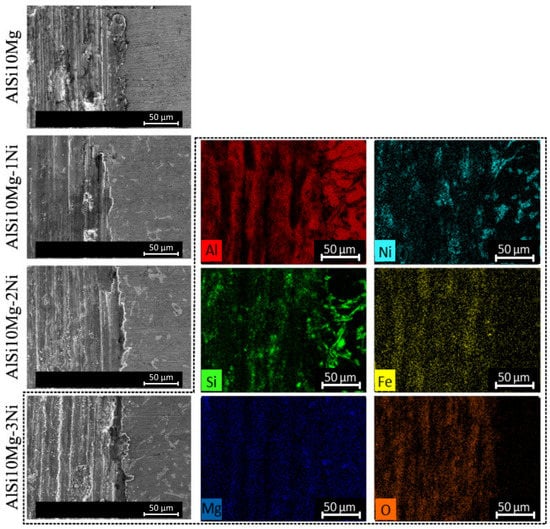
Figure 7.
SEM images and EDS data of the AlSi10Mg(-Ni) alloy DS samples showing damaged worn surfaces.
The short-term wear process (Figure 5b) appears to be related to the layer of compacted debris formed in situ between the alloy and the steel ball. Previous studies of the wear surface and the debris in Al-Si alloys [40,41,42] demonstrated that the layer may be composed of an ultrafine mechanical mixture of oxides, Al, Si, and Fe-bearing particles generated during the wear process. Indeed, when the Si size and distribution are examined after wear, the particles appear fragmented and oriented parallel to the sliding direction, as shown by the green contrast in the EDS elemental mapping in Figure 7.
In the DS samples (Figure 7), the dominant wear mechanisms are associated with the adhesive mode. Notably, long parallel grooves are evident along the sliding direction, and their depth remains consistent regardless of the variation in Ni content. These grooves are a consequence of hard particles becoming trapped during wear testing. Additionally, Si-lined fragmented layers (white lines) appear to be thicker in alloys containing higher Ni content.
In order to show the three-dimensional morphology of the phases, Figure 6 depicts the interdendritic microstructures through SEM images and EDS mapping, i.e., the Si and Al3Ni particles. For all alloys solidified in DS conditions, plate Si particles were found. Although fishbone-type Al3Ni particles predominated in these alloys [36], mostly in the case of the AlSi10Mg-1Ni, a mixture of more compact plates, blocks, and fishbone Al3Ni particles was noted, as indicated by blue arrows in Figure 6. During the short-term and small load tests, the combination of these morphologies and the smaller fraction of Al3Ni might favor a more stable/compact debris layer. The characteristics related to such layer seems to generate an improved wear resistance for the AlSi10Mg-1Ni alloy.
During their research on the wear of six quaternary Al-40Zn-3Cu-(0.5-3)Ni cast alloys, Savaskan et al. [24] also noticed wear surfaces with smearing and scratches. Additionally, Li et al. [25] and Mirzaee-Moghadam et al. [26] developed studies with Ni addition in Al alloys with wear analyses that highlighted the possibility of higher wear resistance for samples having more uniform dispersion of Ni-rich intermetallics and better bonding with the Al-rich matrix.
The parameter that translates the interaction between the dendritic matrix, eutectic mixture, and second phases is dendritic spacing [43]. According to the LSR sample microstructures in Figure 8, very small cells with a narrow range of 1.0 μm to 2.0 μm in spacing are formed. The interdendritic phases arrange themselves into skeletal-like walls of high density. All tested alloys at 100 J/mm2 have a similar overall cellular aspect, despite the fact that the Al3Ni phase is present in quaternary alloys, as demonstrated by the EDS mapping.
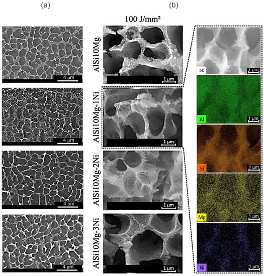
Figure 8.
SEM images in SE mode (a) without etching, and (b) after deep etching with EDS maps of the AlSi10Mg(-Ni) alloy LSR samples before the wear tests.
Figure 8a displays SE mode SEM images taken from the top of the melt pool for samples prepared without chemical etching and with great contrast. As a result, the phases that are formed—α-Al matrix (dark grey), Si (light grey), and Al3Ni (white)—can be highly perceptible. One can notice the predominance of sectioned oriented cells in the cross sections. In other words, the cells at the top of the melt pool shifted their growth orientation with regard to the bottom and began to grow in the same direction as the laser beam, as documented in other investigations in the literature [44,45,46,47].
A fibrous shape of the aggregated phases constituting the skeletal walls was morphologically distinctive in Figure 8b, thanks to the deep etching procedure. Al3Ni is represented by more whitish contrast zones, while Si is represented by more greyish areas. Numerous reports in the literature support the growth of Si fibers in the Al-Si alloys because of the high cooling rates [48,49]. In several previous studies, the growth of Al3Ni fibers was also described as fibrous [19,50]. In accordance with the alignment level of the particles, the research of Canté et al. [50] showed the growth of rod-like Al-Al3Ni eutectic in hypoeutectic binary Al-Ni alloys, which was cited as a source of increasing alloy strength.
According to Stadler et al. [51], the Al3Ni phase contributes to alloy strength by stabilizing the contiguity of the Al-Si eutectic network. Such phase interconnectedness was also observed in the current EDS results in Figure 8b. The short-term wear examination of LSR samples (for 10 min at 0.5 N) revealed no significant differences in terms of Ni content, λ, or energy density in Figure 5b (on the right side of the graph). Moreover, the wear resistance was overall improved due to the laser surface treatment.
Indeed an extremely fine microstructure defined the molten pool boundaries as also reported in the literature for SLMed AlSi10Mg alloys [52]. The present results indicate a high density of cell boundaries, which improved the wear resistance acting as a barrier to plastic deformation, as also demonstrated in a study on AlSi10Mg by Liu et al. [37]. This is also consistent with the findings of Rathod et al. [53] on Al12Si alloys.
Figure 9 depicts less damaged worn surfaces for the LSR samples as compared to those in Figure 7. Wear mechanisms described for similar tribological systems consisting of steel and AlSi10Mg alloy [54,55] match those observed in this study. The observed wear mechanisms include the formation of a protective oxide layer and an adhesive wear mechanism. The EDS mapping reveals evidence of intense iron oxide formation at the sample surface, owing primarily to a possible Fe transfer from the steel ball surface [28]. Long parallel grooves can be seen along the sliding direction. The grooves were the result of hard particles becoming entrapped during wear testing. There may also be evidence of oxide delamination and a few cracks [56].
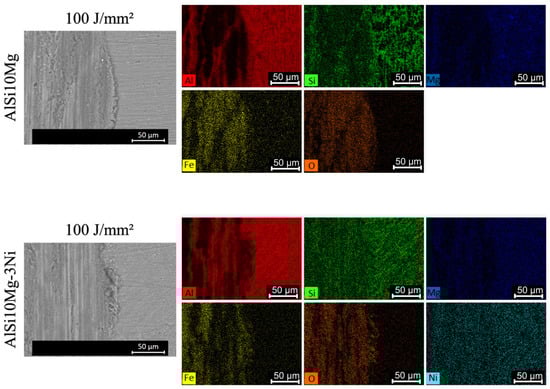
Figure 9.
SEM images and EDS data of the AlSi10Mg(-Ni) alloy LSR samples showing worn surface morphologies.
By comparing the DS and LSR AlSi10Mg-1Ni samples in Figure 5b, which have approximately the same wear volume and very different hardness (DS: 80 HV × LSR: 127 HV), it is possible to confirm the assumption that the original surface microstructure (λ and phase morphologies) and wear mechanisms are more important in determining the alloy wear resistance, considering the tested conditions.
4. Conclusions
LSR enables greater control over the microstructural configuration, resulting in improved wear resistance independent of alloy composition and hardness variations. Moreover, the process of LSR provides a reliable method to enhance wear performance and extend the lifespan of AlSi10Mg(-Ni) alloy components exposed to abrasive or erosive environments. The following conclusions were drawn from the present extensive set of results:
- The DS samples consisted of an α-Al dendrite matrix and eutectic mixture in the interdendritic regions (coarse Si + Al3Ni particles).
- The 1% Ni alloy exhibited growth of Al3Ni plates and blocks, alongside fishbone-like particles.
- The LSR treatment altered the microstructural configuration, forming very small cells (about 100 times smaller than DS dendritic arrays) encased in Si + Al3Ni skeletal arrangements, particularly at the top of the molten pool.
- Vickers hardness tended to increase with decreasing dendritic spacing.
- Short-term wear testing (10 min at 0.5 N) revealed that DS 1% Ni alloy samples had higher resistance due to the stability and compactness of the formed debris layer during wear.
- The LSR samples showed high wear resistance attributed to the high density of cell boundaries acting as a barrier to plastic deformation and preventing cracks in the subsurface regions.
- The wear resistance of the LSR samples appeared to be somewhat independent of Ni content and hardness variations.
Author Contributions
Methodology, D.M., G.G.; formal analysis, D.M., J.S., G.G.; investigation, D.M., G.G.; resources, J.S.; data curation, D.M., G.G.; writing, D.M., J.S.; writing—review and editing, D.M., J.S.; visualization, D.M.; supervision, D.M., J.S.; project administration, D.M., J.S.; funding acquisition, J.S. All authors have read and agreed to the published version of the manuscript.
Funding
This research was funded by CNPq-National Council for Scientific and Technological Development, Brazil and by FAPESP-São Paulo Research Foundation, Brazil (grant number #2019/23673-7).
Acknowledgments
This study was financed in part by the Coordenação de Aperfeiçoamento de Pessoal de Nível Superior-Brasil (CAPES)-FinanceCode 001. The authors take this opportunity to express their gratitude to Nikhilesh Chawla for permitting the use of the Helios G4 UX Dual Beam facility at Purdue University.
Conflicts of Interest
The authors declare no conflict of interest.
References
- Yang, J.; Xiao, M.; Wu, L.; Li, Z.; Liu, H.; Zhao, Y.; Guo, W.; Tan, C. The influence of laser power on microstructure and properties of laser welding-brazing of Al alloys to Al-Si coated 22MnB5 steel. Opt. Laser Technol. 2023, 162, 109318. [Google Scholar] [CrossRef]
- Dash, S.S.; Chen, D. A Review on Processing–Microstructure–Property Relationships of Al-Si Alloys: Recent Advances in Deformation Behavior. Metals 2023, 13, 609. [Google Scholar] [CrossRef]
- Hu, Z.; Huo, Q.; Chen, Y.; Liu, M.; Chen, X. Improving Mechanical Property of Hyper-Eutectic Al-Si Alloys via Regulating the Microstructure by Rheo-Die-Casting. Metals 2023, 13, 968. [Google Scholar] [CrossRef]
- Abdellah, M.Y.; Fadhl, B.M.; Abu El-Ainin, H.M.; Hassan, M.K.; Backar, A.H.; Mohamed, A.F. Experimental Evaluation of Mechanical and Tribological Properties of Segregated Al-Mg-Si Alloy Filled with Alumina and Silicon Carbide through Different Types of Casting Molds. Metals 2023, 13, 316. [Google Scholar] [CrossRef]
- Zhang, Z.; Liu, M.Y.; Breton, F.; Chen, X.G. Microstructure and Mechanical Properties of AlSi10Mg Permanent Mould and High Pressure Vacuum Die Castings. In Proceedings of the 16th International Aluminum Alloys Conference (ICAA16), Montreal, QC, Canada, 17–21 June 2018; pp. 17–21. [Google Scholar]
- Fite, J.; Prameela, S.E.; Slotwinski, J.; Weihs, T.P. Enhanced mechanical properties by eutectic cells in AlSi10Mg—A promising paradigm for strengthening aluminum in additive manufacturing. Mater. Charact. 2023, 204, 113179. [Google Scholar] [CrossRef]
- Moura, D.A.; Gouveia, G.L.; Gomes, L.F.; Spinelli, J.E. Understanding the effect of Ni content on microstructures and tensile properties of AlSi10Mg alloy samples under a variety of solidification rates. J. Alloys Compd. 2022, 924, 166496. [Google Scholar] [CrossRef]
- Yan, Q.; Song, B.; Shi, Y. Comparative Study of Performance Comparison of AlSi10Mg Alloy Prepared by Selective Laser Melting and Casting. J. Mater. Sci. Technol. 2020, 41, 199–208. [Google Scholar] [CrossRef]
- Yang, C.-Y.; Lee, S.-L.; Lee, C.-K.; Lin, J.-C. Effects of Sr and Sb Modifiers on the Sliding Wear Behavior of A357 Alloy under Varying Pressure and Speed Conditions. Wear 2006, 261, 1348–1358. [Google Scholar] [CrossRef]
- Tavitas-Medrano, F.J.; Gruzleski, J.E.; Samuel, F.H.; Valtierra, S.; Doty, H.W. Effect of Mg and Sr-Modification on the Mechanical Properties of 319-Type Aluminum Cast Alloys Subjected to Artificial Aging. Mater. Sci. Eng. A 2008, 480, 356–364. [Google Scholar] [CrossRef]
- Abouei, V.; Shabestari, S.G.; Saghafian, H. Dry Sliding Wear Behaviour of Hypereutectic Al–Si Piston Alloys Containing Iron-Rich Intermetallics. Mater. Charact. 2010, 61, 1089–1096. [Google Scholar] [CrossRef]
- Zykova, A.; Martyushev, N.; Skeeba, V.; Zadkov, D.; Kuzkin, A. Influence of W Addition on Microstructure and Mechanical Properties of Al-12%Si Alloys. Materials 2019, 12, 981. [Google Scholar] [CrossRef] [PubMed]
- Li, Q.; Xia, T.; Lan, Y.; Zhao, W.; Fan, L.; Li, P. Effect of in Situ γ-Al2O3 Particles on the Microstructure of Hypereutectic Al–20%Si Alloy. J. Alloys Compd. 2013, 577, 232–236. [Google Scholar] [CrossRef]
- Li, Y.; Yang, Y.; Wu, Y.; Wei, Z.; Liu, X. Supportive Strengthening Role of Cr-Rich Phase on Al–Si Multicomponent Piston Alloy at Elevated Temperature. Mater. Sci. Eng. A 2011, 528, 4427–4430. [Google Scholar] [CrossRef]
- Shaha, S.K.; Czerwinski, F.; Kasprzak, W.; Friedman, J.; Chen, D.L. Thermal Stability of (AlSi) (ZrVTi) Intermetallic Phases in the Al–Si–Cu–Mg Cast Alloy with Additions of Ti, V, and Zr. Thermochim. Acta 2014, 595, 11–16. [Google Scholar] [CrossRef]
- Feng, J.; Ye, B.; Zuo, L.; Qi, R.; Wang, Q.; Jiang, H.; Huang, R.; Ding, W. Effects of Ni Content on Low Cycle Fatigue and Mechanical Properties of Al-12Si-0.9Cu-0.8Mg-XNi at 350 °C. Mater. Sci. Eng. A 2017, 706, 27–37. [Google Scholar] [CrossRef]
- Li, Y.; Yang, Y.; Wu, Y.; Wang, L.; Liu, X. Quantitative Comparison of Three Ni-Containing Phases to the Elevated-Temperature Properties of Al–Si Piston Alloys. Mater. Sci. Eng. A 2010, 527, 7132–7137. [Google Scholar] [CrossRef]
- Farkoosh, A.R.; Javidani, M.; Hoseini, M.; Larouche, D.; Pekguleryuz, M. Phase Formation in As-Solidified and Heat-Treated Al–Si–Cu–Mg–Ni Alloys: Thermodynamic Assessment and Experimental Investigation for Alloy Design. J. Alloys Compd. 2013, 551, 596–606. [Google Scholar] [CrossRef]
- Zhuang, Y.X.; Zhang, X.M.; Zhu, L.H.; Hu, Z.Q. Eutectic Spacing and Faults of Directionally Solidified Al–Al3 Ni Eutectic. Sci. Technol. Adv. Mater. 2001, 2, 37–39. [Google Scholar] [CrossRef]
- Hunt, W.H., Jr. New Directions in Aluminum-Based P/M Materials for Automotive Applications. SAE Trans. 2000, 109, 90–97. [Google Scholar]
- Rakhmonov, J.; Liu, K.; Pan, L.; Breton, F.; Chen, X.-G. Enhanced Mechanical Properties of High-Temperature-Resistant Al–Cu Cast Alloy by Microalloying with Mg. J. Alloys Compd. 2020, 827, 154305. [Google Scholar] [CrossRef]
- Manohara, H.R.; Chandrashekharaiah, T.M.; Venkateswarlu, K.; Kori, S.A. Dry Sliding Wear Response of A413 Alloy: Influence of Intermetallics and Test Parameters. Tribol. Int. 2012, 51, 54–60. [Google Scholar] [CrossRef]
- Miranda, G.; Buciumeanu, M.; Carvalho, O.; Soares, D.; Silva, F.S. Interface Analysis and Wear Behavior of Ni Particulate Reinforced Aluminum–Silicon Composites Produced by PM. Compos. Part B Eng. 2015, 69, 101–110. [Google Scholar] [CrossRef]
- Savaşkan, T.; Alemdağ, Y. Effect of Nickel Additions on the Mechanical and Sliding Wear Properties of Al–40Zn–3Cu Alloy. Wear 2010, 268, 565–570. [Google Scholar] [CrossRef]
- Liu, Y.; Jia, L.; Wang, W.; Jin, Z.; Zhang, H. Effects of Ni Content on Microstructure and Wear Behavior of Al–13Si–3Cu–1Mg-XNi–0.6Fe–0.6Mn Alloys. Wear 2022, 500–501, 204365. [Google Scholar] [CrossRef]
- Mirzaee-Moghadam, M.; Lashgari, H.R.; Zangeneh, S.; Rasaee, S.; Seyfor, M.; Asnavandi, M.; Mojtahedi, M. Dry Sliding Wear Characteristics, Corrosion Behavior, and Hot Deformation Properties of Eutectic Al–Si Piston Alloy Containing Ni-Rich Intermetallic Compounds. Mater. Chem. Phys. 2022, 279, 125758. [Google Scholar] [CrossRef]
- Xavier, M.G.C.; Freitas, B.J.M.; Koga, G.Y.; Spinelli, J.E. Effects of Ni and Co on the Corrosion Resistance of Al-Si-Cu-Zn-Fe Alloys in NaCl Solution. Metals 2022, 12, 645. [Google Scholar] [CrossRef]
- Freitas, E.S.; Silva, A.P.; Spinelli, J.E.; Casteletti, L.C.; Garcia, A. Inter-Relation of Microstructural Features and Dry Sliding Wear Behavior of Monotectic Al–Bi and Al–Pb Alloys. Tribol. Lett. 2014, 55, 111–120. [Google Scholar] [CrossRef]
- Silva, A.S.; de Albuquerque Sousa, S.M.; de Gouveia, G.L.; Garcia, A.; Spinelli, J.E. The influence of NbB inoculation on dendritic spacing and grain size of an aluminum 2017 alloy at different cooling rates. Int. J. Adv. Manuf. Technol. 2023, 125, 5681–5696. [Google Scholar] [CrossRef]
- Cruz, K.S.; Meza, E.S.; Fernandes, F.A.P.; Quaresma, J.M.V.; Casteletti, L.C.; Garcia, A. Dendritic Arm Spacing Affecting Mechanical Properties and Wear Behavior of Al-Sn and Al-Si Alloys Directionally Solidified under Unsteady-State Conditions. Metall. Mater. Trans. A 2010, 41, 972–984. [Google Scholar] [CrossRef]
- Savaşkan, T.; Bican, O. Dry Sliding Friction and Wear Properties of Al–25Zn–3Cu–3Si Alloy. Tribol. Int. 2010, 43, 1346–1352. [Google Scholar] [CrossRef]
- Dong, Y.J.; Wang, H.M. Microstructure and Dry Sliding Wear Resistance of Laser Clad TiC Reinforced Ti–Ni–Si Intermetallic Composite Coating. Surf. Coat. Technol. 2009, 204, 731–735. [Google Scholar] [CrossRef]
- Gündüz, M.; Çadırlı, E. Directional Solidification of Aluminium–Copper Alloys. Mater. Sci. Eng. A 2002, 327, 167–185. [Google Scholar] [CrossRef]
- Valenzuela Reyes, R.A.; Garcia, A.; Spinelli, J.E. Evaluating Microstructure, Wear Resistance and Tensile Properties of Al-Bi(-Cu, -Zn) Alloys for Lightweight Sliding Bearings. Metals 2021, 11, 153. [Google Scholar] [CrossRef]
- Brito, C.; Costa, T.A.; Vida, T.A.; Bertelli, F.; Cheung, N.; Spinelli, J.E.; Garcia, A. Characterization of Dendritic Microstructure, Intermetallic Phases, and Hardness of Directionally Solidified Al-Mg and Al-Mg-Si Alloys. Metall. Mater. Trans. A 2015, 46, 3342–3355. [Google Scholar] [CrossRef]
- Kakitani, R.; Cruz, C.B.; Lima, T.S.; Brito, C.; Garcia, A.; Cheung, N. Transient Directional Solidification of a Eutectic Al–Si–Ni Alloy: Macrostructure, Microstructure, Dendritic Growth and Hardness. Materialia 2019, 7, 100358. [Google Scholar] [CrossRef]
- Liu, Y.J.; Liu, Z.; Jiang, Y.; Wang, G.W.; Yang, Y.; Zhang, L.C. Gradient in Microstructure and Mechanical Property of Selective Laser Melted AlSi10Mg. J. Alloys Compd. 2018, 735, 1414–1421. [Google Scholar] [CrossRef]
- Kurz, W.; Fisher, D. Fundamentals of Solidification, 4th ed.; Trans Tech Publications: Zurich, Switzerland, 1998. [Google Scholar]
- Reddy, A.S.; Bai, B.N.P.; Murthy, K.S.S.; Biswas, S.K. Wear and Seizure of Binary Al Si Alloys. Wear 1994, 171, 115–127. [Google Scholar] [CrossRef]
- Razavizadeh, K.; Eyre, T.S. Oxidative Wear of Aluminium Alloys. Wear 1982, 79, 325–333. [Google Scholar] [CrossRef]
- Razavizadeh, K.; Eyre, T.S. Oxidative Wear of Aluminium Alloys: Part II. Wear 1983, 87, 261–271. [Google Scholar] [CrossRef]
- Antoniou, R.; Borland, D.W. Mild Wear of AlSi Binary Alloys during Unlubricated Sliding. Mater. Sci. Eng. 1987, 93, 57–72. [Google Scholar] [CrossRef]
- Spinelli, J.E.; Silva, B.L.; Garcia, A. Assessment of Tertiary Dendritic Growth and Its Effects on Mechanical Properties of Directionally Solidified Sn-0.7Cu-XAg Solder Alloys. J. Electron. Mater. 2014, 43, 1347–1361. [Google Scholar] [CrossRef]
- Gill, S.C.; Zimmermann, M.; Kurz, W. Laser Resolidification of the AlAl2Cu Eutectic: The Coupled Zone. Acta Metall. Mater. 1992, 40, 2895–2906. [Google Scholar] [CrossRef]
- Pinto, M.A.; Cheung, N.; Ierardi, M.C.F.; Garcia, A. Microstructural and Hardness Investigation of an Aluminum–Copper Alloy Processed by Laser Surface Melting. Mater. Charact. 2003, 50, 249–253. [Google Scholar] [CrossRef]
- Yao, Z.; Ren, W.; Allison, J. Microstructure and Microsegregation Characterization of Laser Surfaced Remelted Al-3wt%Cu Alloys. Res. Sq. 2021. preprint. [Google Scholar] [CrossRef]
- Wang, J.; Wang, H.; Gao, H.; Yang, J.; Zhang, M.; Cheng, X.; Zhang, S.; Liu, D. Crystal Growth for Different Substrate Orientations during Laser Directed Solidification of Single Crystal Superalloys. J. Alloys Compd. 2023, 957, 170219. [Google Scholar] [CrossRef]
- Zhou, X.; Chao, P.; Sloan, L.; Lien, H.; Hunter, A.H.; Misra, A.; Shahani, A.J. Three-dimensional morphology of an ultrafine Al-Si eutectic produced via laser rapid solidification. Scr. Mater. 2023, 232, 115471. [Google Scholar] [CrossRef]
- Spinelli, J.E.; Bogno, A.-A.; Henein, H. Two-Zone Microstructures in Al-18Si Alloy Powders. Metall. Mater. Trans. A 2018, 49, 550–562. [Google Scholar] [CrossRef]
- Canté, M.V.; Spinelli, J.E.; Ferreira, I.L.; Cheung, N.; Garcia, A. Microstructural Development in Al-Ni Alloys Directionally Solidified under Unsteady-State Conditions. Metall. Mater. Trans. A 2008, 39, 1712–1726. [Google Scholar] [CrossRef]
- Stadler, F.; Antrekowitsch, H.; Fragner, W.; Kaufmann, H.; Uggowitzer, P.J. The Effect of Ni on the High-Temperature Strength of Al-Si Cast Alloys. Mater. Sci. Forum 2011, 690, 274–277. [Google Scholar] [CrossRef]
- Xiong, Z.H.; Liu, S.L.; Li, S.F.; Shi, Y.; Yang, Y.F.; Misra, R.D.K. Role of Melt Pool Boundary Condition in Determining the Mechanical Properties of Selective Laser Melting AlSi10Mg Alloy. Mater. Sci. Eng. A 2019, 740–741, 148–156. [Google Scholar] [CrossRef]
- Rathod, H.J.; Nagaraju, T.; Prashanth, K.G.; Ramamurty, U. Tribological Properties of Selective Laser Melted Al 12Si Alloy. Tribol. Int. 2019, 137, 94–101. [Google Scholar] [CrossRef]
- Thasleem, P.; Kuriachen, B.; Kumar, D.; Ahmed, A.; Joy, M.L. Effect of Heat Treatment and Electric Discharge Alloying on the Tribological Performance of Selective Laser Melted AlSi10Mg. J. Tribol. 2021, 143, 2100147. [Google Scholar] [CrossRef]
- Mishra, A.K.; Upadhyay, R.K.; Kumar, A. Surface Wear Anisotropy in AlSi10Mg Alloy Sample Fabricated by Selective Laser Melting: Effect of Hatch Style, Scan Rotation and Use of Fresh and Recycled Powder. J. Tribol. 2021, 143, 021701. [Google Scholar] [CrossRef]
- Tonolini, P.; Montesano, L.; Tocci, M.; Pola, A.; Gelfi, M. Wear Behavior of AlSi10Mg Alloy Produced by Laser-Based Powder Bed Fusion and Gravity Casting. Adv. Eng. Mater. 2021, 23, 2100147. [Google Scholar] [CrossRef]


Disclaimer/Publisher’s Note: The statements, opinions and data contained in all publications are solely those of the individual author(s) and contributor(s) and not of MDPI and/or the editor(s). MDPI and/or the editor(s) disclaim responsibility for any injury to people or property resulting from any ideas, methods, instructions or products referred to in the content. |
© 2023 by the authors. Licensee MDPI, Basel, Switzerland. This article is an open access article distributed under the terms and conditions of the Creative Commons Attribution (CC BY) license (https://creativecommons.org/licenses/by/4.0/).