Article

Mechanical and Corrosion Behavior of a Composite Gradient-Structured Cu-Fe Alloy

1
Institute of Applied Physics, Jiangxi Academy of Sciences, Nanchang 330029, China
2
School of Engineering, Huzhou University, Huzhou 313000, China
3
International Joint Laboratory for Light Alloys, College of Materials Science and Engineering, Chongqing University, Chongqing 400030, China
4
Institute of Corrosion Science and Technology, Guangzhoug 510070, China
5
School of Advanced Manufacturing, Nanchang University, Nanchang 330031, China
*
Authors to whom correspondence should be addressed.
These authors contributed equally to this work.
Metals 2023, 13(7), 1304; https://doi.org/10.3390/met13071304
Submission received: 21 June 2023 / Revised: 17 July 2023 / Accepted: 19 July 2023 / Published: 21 July 2023

Abstract

:
Immiscible Cu-Fe alloys exhibit poor corrosion resistance due to different corrosion potentials between the constituent phases, which limits their application. In this paper, a composite gradient-structured Cu-10 wt.%Fe plate was prepared via the ultrasonic surface rolling process (USRP). The microstructure evolution, mechanical properties and corrosion behavior were studied. The results demonstrate that USRP effectively enhances both the strength and corrosion resistance of the Cu-10Fe alloy. The improved strength is related to the combined effects of Hall–Petch strengthening, dislocation strengthening, and additional strengthening resulting from homogeneous deformation between the surface layer and the matrix. The enhanced corrosion resistance is primarily attributed to the refined microstructure of the surface layer after USRP, which facilitates the formation of a protective passivation film.

1. Introduction

Cu-Fe binary alloys exhibit high strength [1], electrical conductivity [2] and excellent electromagnetic shielding performance [3], making them suitable for potential applications in integrated circuits and base stations [4]. Additionally, Cu-Fe alloys have a lower material cost, comparing with other competing Cu alloys, such as Cu-Al [5], Cu-Ni [6], Cu-Zn [7], Cu-Cr [8], etc. [9,10]. It has been reported that the mechanical and functional properties of the Cu-Fe binary alloys could be well controlled by adjusting the Fe phase content [2,11,12]. For instance, increasing the Fe content from 5 wt.% to 70 wt.% in Cu-Fe alloys resulted in a strength increase from 305 MPa to 736 MPa [13]. Therefore, Cu-Fe alloys are expected to be extensively used in the electronic devices.
The Cu-Fe alloy is a typical immiscible alloy [14]. The solid solubility of Fe in Cu is 4 wt.% at 1084 °C, which significantly decreases to 1.66 wt.% at 850 °C and 0.21 wt.% at 650 °C [15,16]. Consequently, the Cu-Fe alloy is generally composed of a stable Cu phase and Fe phase at room temperature [4]. Materials with dual- or multi-phase structures typically exhibit poor corrosion resistance due to severe galvanic corrosion resulting from the different corrosion potentials between the constituent phases [17,18]. EI-Egamy [15] investigated the electrochemical behavior of Cu and Cu-20 wt.% Fe in a sodium chloride solution. The electrochemical test results indicated that the polarization resistance, corrosion current density and corrosion potential for Cu were 503 Ω cm2, 43.6 μA/cm2 and −0.247 V, respectively, while they were 255.5 Ω cm2, 120.2 μA/cm2 and −0.572 V, respectively, for Cu-20 wt.% Fe alloy. The decreased corrosion potential and increased corrosion current density suggested that the presence of the Fe phase in the Cu matrix deteriorated corrosion resistance of Cu alloy. Thus, improving the corrosion resistance of the Cu-Fe alloy is an important research topic. The study by EI-Egamy shown that the corrosion behavior of Cu-20 wt.% Fe alloy could be controlled by the addition of Thiourea into the solution [15]. Mahmoud [19] studied the effect of different concentration of inorganic additives, such as WO42−, PO43−, NO22−, B4O72− and CrO42−, on the corrosion behaviors of Cu-30 wt.% Fe alloy in 0.5 M NaCl. The results indicate that the investigated inorganic additives had an inhibiting effect on the corrosion rate of Cu-30 wt.% Fe alloy, and the inhibiting efficiency decreased according to the order WO42− > PO43− > NO22− > B4O72− > CrO42−. The previous study mainly focused on inhibiting the corrosion behavior of Cu-Fe alloys using inorganic additives, whereas enhancing the intrinsic corrosion resistance of Cu-Fe alloys remains a challenge [19].
Corrosion failure generally starts from the surface of the specimen [20]. Recently, surface strengthening by ultrasonic surface rolling process (USRP) has proved to be a promising way to improve the corrosion resistance of metals [20]. Xu et al. [20] reported that the corrosion resistance of 42CrMo4 steel could be enhanced via USRP, with the corrosion current density decreasing from 2.748 μA·cm−2 decreased to 45.2%, and the charge transfer resistance increasing up to 19.6%. The results by Xia et al. [21] showed that USRP could also increase the corrosion resistance of Cu-10Ni alloys comparative to that of initial coarse-grained sample. In this study, USRP was employed, and the effect of USRP on the mechanical and corrosion properties of Cu-10Fe alloy were investigated. The results demonstrated that USRP effectively improve both the corrosion resistance and strength of Cu-10Fe alloy. Furthermore, the synergistic mechanisms underlying the effects of USRP on corrosion behavior and mechanical properties were systematically studied.

2. Materials and Methods

2.1. Material Preparation

A 2 mm-thick Cu-10 wt.% Fe hot-rolled plate was subjected to the ultrasonic surface rolling process (USRP). During USRP, the down-force of the head is about 135 N, and the total number of rolling passes is 15 passes. A similar method can be found in our previous reports [22].

2.2. Mechanical Tests

Vickers micro-hardness tests were conducted using a micro-hardness test machine (HXD1000TMSC/LG, Shanghai Taiming Optical Instrument Corp., Shanghai, China). During the test, a force of 200 g was applied for 10 s. The hardness distribution of the USRPed Cu-10Fe alloy was determined by measuring the hardness at various distances from the surface. Each measurement was repeated three times with a spacing of 60 μm. Tensile tests were carried out on both the hot-rolled plate and the USRPed plate using an MTS machine (20 kN) at a strain rate of 10−3 s−1. Dog-bone-shaped specimens with a gauge length of 15 mm and a cross-section of 3 × 2 mm were used for the tensile tests. At least three samples were tested for each plate.

2.3. Electrochemical Measurements

All electrochemical tests were performed at 25 °C using an electrochemical workstation (Princeton P4000). A three-electrode system was employed. The Cu-Fe alloy is the working electrode, a saturated calomel electrode is used as the reference electrode, and a platinum foil is used as the counter electrode. The samples for electrochemical impedance tests were coated by epoxy resin, leaving an exposed surface area of 1 × 1 cm2. Subsequently, the polished samples were quickly immersed in 3.5 wt.% NaCl solution. Before electrochemical tests, the samples were immersed in the NaCl solution for 2000 s under open circuit potential (OCP) tests to obtain a stable potential. The electrochemical impedance spectroscopy (EIS) tests were performed in the frequency range from 105 Hz to 10−1 Hz with a perturbation amplitude of 5 mV. The EIS data were analyzed using the Zview2 software package. The polarization measurements were conducted with a scanning rate of 2 mV/s, in the range of about −900 mV (vs. SCE) to −100 mV (vs. SCE). The results were analyzed using the Versastudio 2.62.2 software package.

2.4. Microstructure Examination

Samples for scanning electron microscopy (SEM) and electron backscatter diffraction (EBSD) observation were meticulously polished using a polishing cloth with silicon dioxide suspension. SEM and EBSD measurements were carried out using a Zeiss electron microscope (Zeiss EVO 18, Jena, Germany) equipped with an HKL-EBSD system. The EBSD data were analyzed using the Channel 5 software package. The surface morphology was examined using a White Light Interferometer (Contour X500, Bruke Nano Inc., Goleta, CA, USA) to obtain three-dimensional images. The microstructure of topmost surface of the USRPed Cu-Fe plate was examined by using a JEM-2100 transmission electron microscopy operating at 200 kV. In situ electrochemical optical microscope observation was performed using equipment that combines an optical microscope (OM, Nikon MA200, Tokyo, Japan) and electrochemical workstation.

3. Results

The microstructure of the initial plate is presented in Figure 1. From the backscatter image in Figure 1a, it can be observed that the Fe phase appears darker than the Cu matrix, and a lamellar structure with an elongated Fe phase along the rolling direction is visible. Figure 2 shows the representative microstructure of the USRPed Cu-Fe plate. It is evident that the surface microstructure has been refined, and a composite gradient structure is observed, with the grain size of the Cu phase and Fe phase gradually increasing from the topmost surface to the matrix. The severely refined surface microstructure indicates significant plastic deformation in both the Cu matrix and Fe phases during USRP. This gradient structure is similar to those observed in other alloys, such as medium entropy alloy [22]. The surface morphology of the Cu-Fe plate before and after ultrasonic surface rolling process were examined and shown in Figure 3. It is evident that ultrasonic surface rolling process could also effectively reduce the surface roughness.
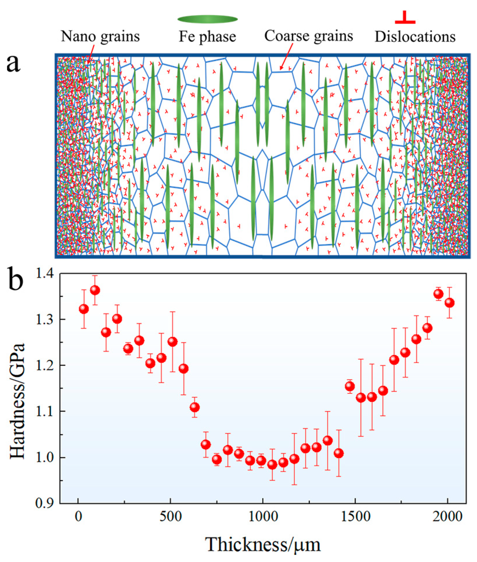
The schematic diagram of the gradient structure and the corresponding micro-hardness evolution with distance away from the surface are depicted in Figure 4. The micro-hardness of the surface layer is approximately 1.36 GPa, which is about 0.38 GPa higher than that of the matrix (approximately 0.98 GPa). The hardness of the USRPed plate gradually decreases from the topmost surface to the matrix. The depth of the gradient structure, as shown in Figure 4b, is approximately 600 μm.
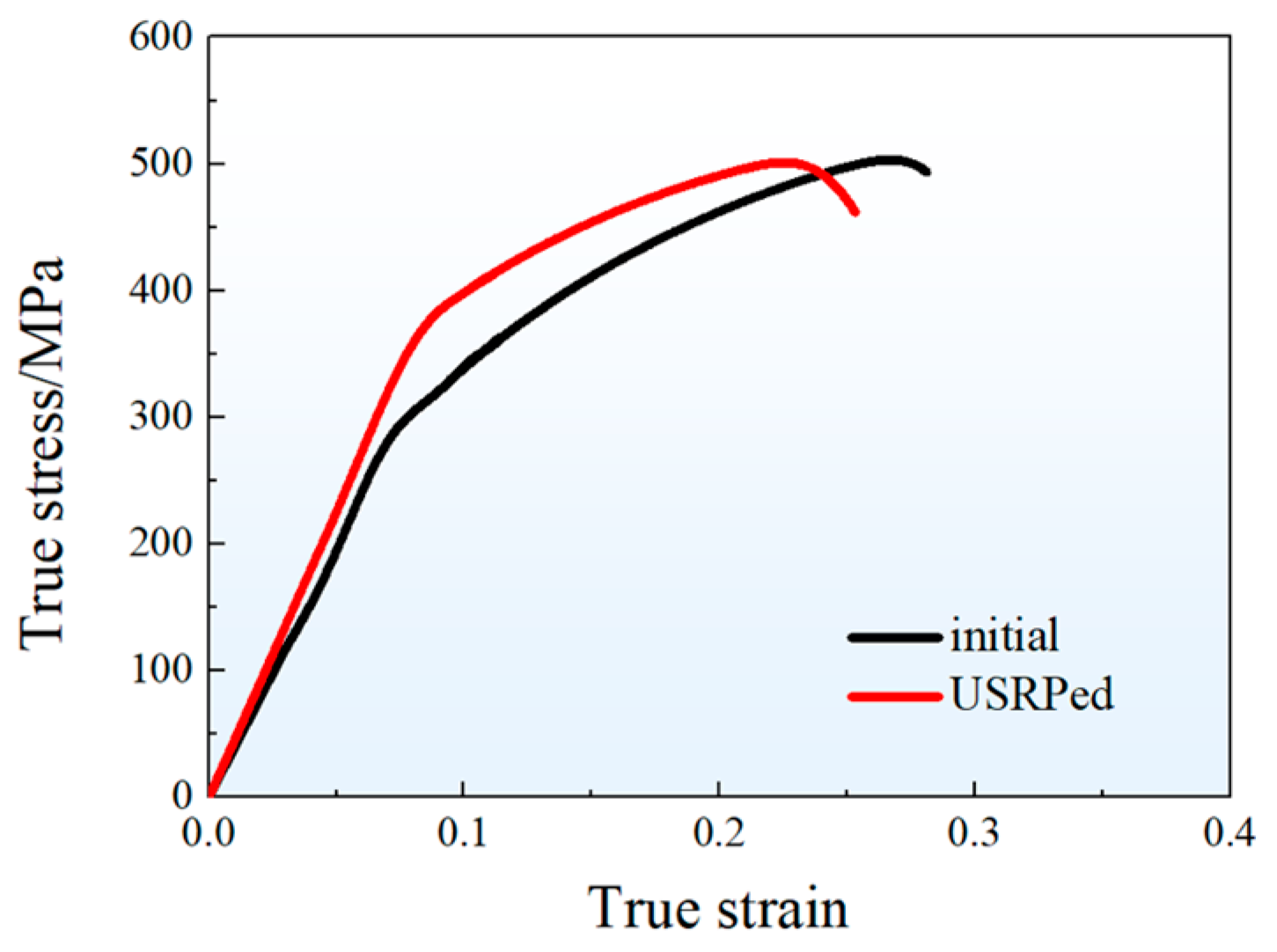
Figure 5 presents the representative stress–strain curves of the hot-rolled plate (initial) and the USRPed plate during tension along the rolling direction at room temperature. Both of the curves exhibit a similar shape, with the stress increasing rapidly in the elastic deformation stage and then gradually in the plastic deformation stage. The mechanical properties of both plates are recorded and summarized in Table 1. The yield strength of the USRPed plate is approximately 378 MPa, which is 81 MPa higher than that of the initial plate (297 MPa). The ultimate tensile strength is similar for both plates, with values of 504 MPa for the initial plate and 500 MPa for the USRPed plate. However, the uniform elongation for USRPed plate is 14.6%, which is about 4.5% lower than that of the initial plate.
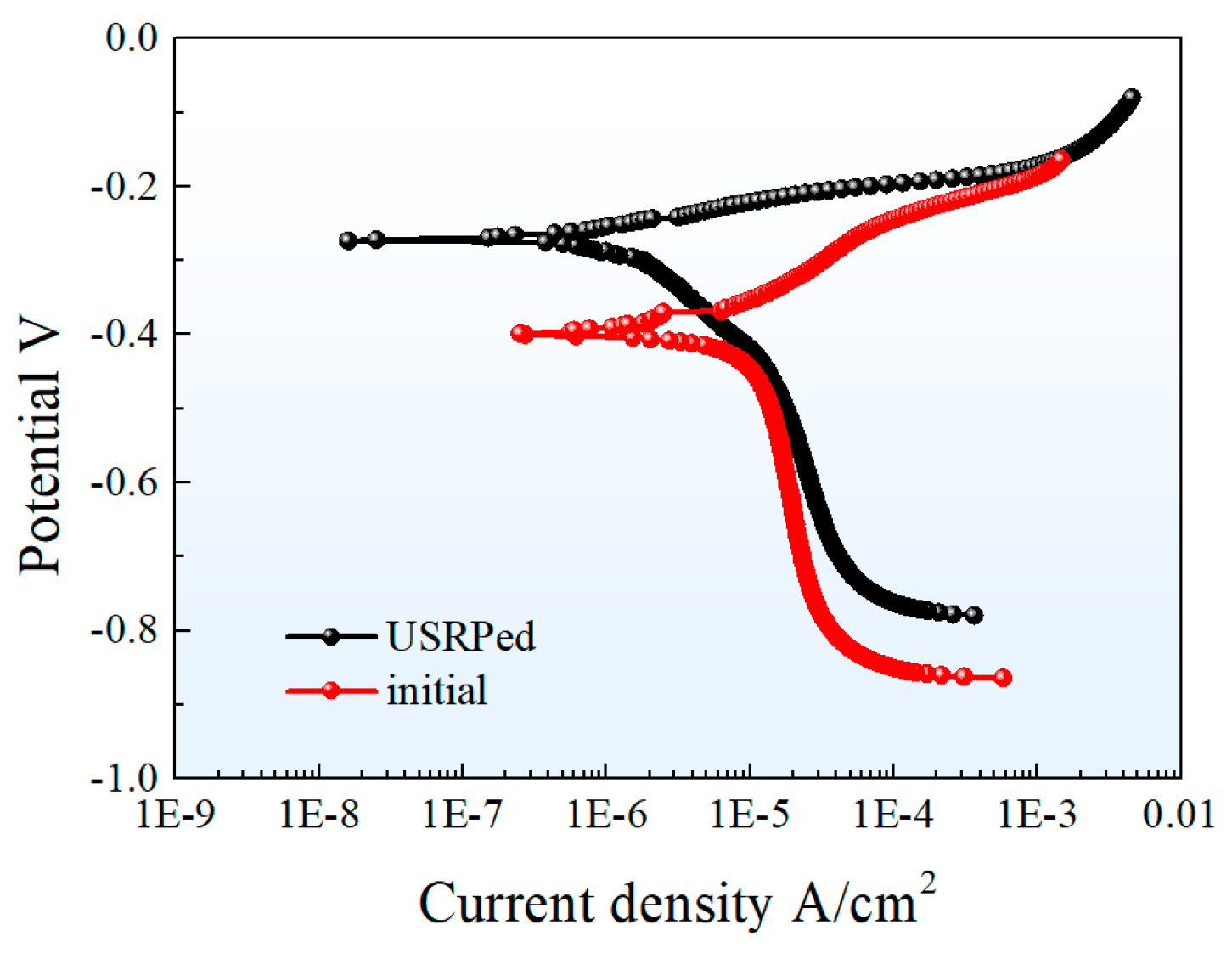
The effect of USRP on the corrosion resistance of Cu-10Fe alloy in 3.5 wt.% NaCl solution was investigated using the electrochemical tests. The results in Figure 6 show the potential dynamic polarization curves of the USRPed plate and the initial plate. The curves indicate a similar corrosion mechanism for both samples. The corrosion current densities ( i c o r r ), corresponding corrosion potentials ( E c o r r ) and polarization resistance ( R p ) of the initial Cu-10Fe sample and the USRPed Cu-10Fe sample are calculated and listed in Table 2. The corrosion potential of the USRPed sample is −0.272 VSCE, which is higher than that of the initial sample (−0.396 VSCE). The corrosion current density of the initial Cu-Fe plate and the USRPed Cu-Fe plate is 11.405 μA/cm2 and 3.238 μA/cm2, respectively. The polarization resistance of USRPed Cu-Fe plate is 1.13 Ω·cm2, which is 0.57 Ω·cm2 higher than that of initial plate.
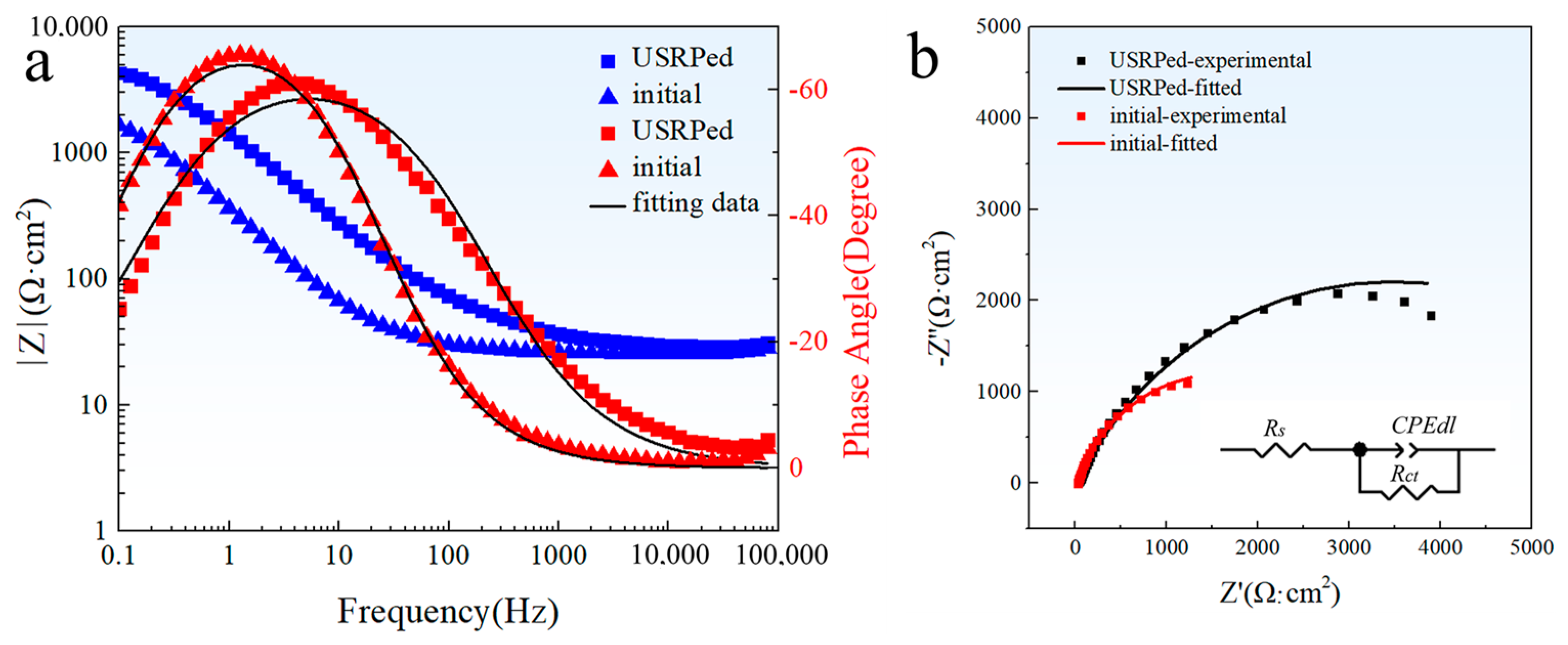
The EIS spectra of the USRPed plate and the initial plate in a 3.5 wt.% NaCl solution are shown in the form of a Bode plot and a Nyquist plot, as depicted in Figure 7. From Figure 7a, the maximum phase angle of the USRPed plate moves toward the high frequency region, and the impedance of the USRPed Cu-Fe plate is higher compared to that of the initial Cu-Fe plate, which indicates an enhanced corrosion resistance. It is evident from Figure 7b that the diameter of the semicircular curve of the initial Cu-Fe alloy increased significantly after undergoing USRP. This indicates a reduced dissolution rate of the plate. The obtained results were fitted to an equivalent circuit model, as presented in Figure 7b. In this equivalent circuit, Rs represents the solution resistance, the CPEdl parameter corresponds to a non-ideal double layer capacitive behavior for metal/solution interface, Rct is the charge transfer resistance, and Q and n represent coefficients of CPE, respectively. The fitted parameters are provided in Table 3. The electrolyte resistance of the initial plate and the USRPed plate is 26.64 and 30.43 Ω·cm2, respectively, which is very close. This means the impedance measurements were performed at a similar condition. The charge transfer resistance of the USRPed plate is 6806 Ω·cm2, which is double than that of the initial plate (3132 Ω·cm2).

4. Discussion

The above results suggest that the mechanical and corrosion properties of the Cu-10Fe alloy could be effectively enhanced through the ultrasonic surface rolling process (USRP). In this section, we will explore the underlying mechanisms responsible for these improvements.

4.1. Mechanism for Improving the Strength of Cu-10Fe Alloy via USRP

Based on the results obtained from hardness tests and tension tests, it is evident that the strength of the Cu-10Fe alloy was significantly improved through USRP.
As shown in Figure 4b, the micro-hardness of the topmost layer is approximately 1.36 GPa, which is higher than that of the matrix (0.98 GPa). Furthermore, the yield strength of the USRPed sample (378 MPa) surpasses that of the initial hot-rolled sample (297 MPa). During the USRP process, severe plastic deformation occurs at the surface layer of the Cu-Fe plate, leading to a reduction in grain size and second-phase particle size, as depicted in Figure 2. The high fraction of grain boundaries and phase boundaries effectively hinders and accumulates dislocations, thereby significantly improving the strength of surface layer.
In addition to the conventional Hall–Petch strengthening effect resulting from grain size refinement and increased dislocation density, the gradient structure introduced via USRP contributes to additional strength. This arises from the synergistic deformation behavior between heterogeneous domains [23]. As illustrated in Figure 4, the micro-hardness of the topmost surface layer is much higher than that of the matrix. This mechanical incompatibility generates strong deformation inhomogeneity during loading.
It has been reported that the extra strengthening induced by heterogeneous deformation in the gradient-structured material could be calculated using the following equation [24]:
Δ σ e x t r a = Δ σ g r a d i e n t Δ σ H V
Here, Δ σ e x t r a represents the additional strengthening induced by incompatible deformation between the surface layer and the matrix, Δ σ g r a d i e n t corresponds to the strength difference between the yield strengths of the gradient-structured samples and coarse-grained sample, and Δ σ H V denotes the strength increment induced by refined grains and enhanced dislocations density. For materials with homogeneous structure, there is a quantitative relationship between yield strength and micro-hardness, given by:
σ y = k × H V
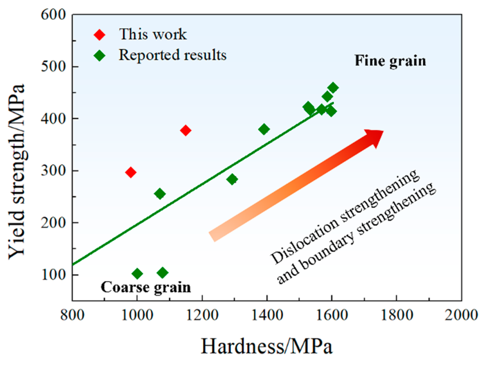
where k is the slope. Figure 8 provides a literature review on the variation in yield strength with micro-hardness for Cu-Fe alloys with different grain sizes [4,25,26]. Based on the reported results, a value of k = 0.387 was obtained, slightly higher than the reported value of approximately 0.3 [24]. Consequently, Δ σ H V could be calculated as:
Δ σ H V = 0.387 × Δ H V ¯
Δ H V ¯ captures the hardness increment of the gradient-structured plate compared to the initial plate, which could be calculated by:
Δ H V ¯ = V i H V i V i H V i n i t i a l
where V i and H V i are the volume fraction and corresponding hardness, and H V i n i t i a l is the micro-hardness of the initial plate. Based on the above equations, the extra strengthening in the gradient materials is about 15.6 MPa, about 19.2% higher compared to the strength increment induced by USRP.
Plastic deformation is known to significantly enhance the strength of metallic materials, but it often comes at the expense of ductility in homogeneous structures [12,27]. For instance, in the case of cold-rolled Cu-10Fe alloy, the tensile strength increases while the elongation decreases with an increasing rolling reduction. For a rolled plate with a reduction of 60%, the tensile strength rapidly increased from 340 MPa (as-cast) to 483 MPa, while the elongation decreased from 18.9% (as-cast) to 6.1% [28]. However, the gradient-structured material offers the potential for achieving high strength–ductility synergy [29,30,31,32]. In a gradient-grained structure, plastic deformation initially activates in the coarse grains and then propagates into smaller grains as the applied load increases. This prevents strain localization and facilitates a stronger strength–ductility synergy [33,34,35]. In the present study, the yield strength of hot-rolled Cu-10Fe alloy increased by approximately 81 MPa through USRP while maintaining a high uniform elongation of 14.6% for the USRPed plate, as shown in Figure 5.

4.2. Mechanism for Inhibiting the Corrosion Behavior of Cu-Fe Alloy via USRP

According to the results of electrochemical tests, the USRPed sample exhibited higher corrosion potentials and polarization resistance, as well as a lower corrosion current density, reaffirming the positive effect of USRP on the corrosion behavior of the Cu-10Fe alloy.
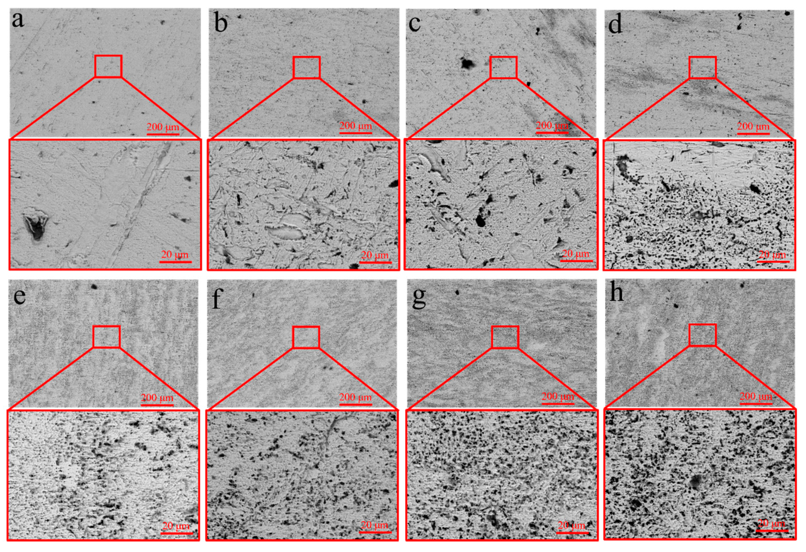
To investigate the mechanism by which USRP improves the corrosion resistance of the Cu-10Fe alloy, the evolution of the surface morphology of the initial and USRPed Cu-10Fe samples immersed in a 3.5 wt.% NaCl solution was examined. Figure 9 displays the surface morphologies of the USRPed plate and the initial plate after immersion in the NaCl solution for 1–7 days. It is observed that the surface of the initial plate immersed for 1 day exhibits large corrosion pits, and the number of pits significantly increases over time. After 7 days of immersion, numerous corrosion pits appear on the surface of the initial plate. In the case of the USRPed plate, corrosion pits are also present, but they are more uniform and smaller compared to those on the initial plate under the same conditions. Figure 10 presents three-dimensional images of the corrosion morphology of the USRPed plate and initial Cu-10Fe plate after 28 days of immersion, further confirming that the size of the corrosion pits on the surface of Cu-10Fe plates dramatically decreased after undergoing USRP.
The evolution of the surface morphology of the initial Cu-Fe plate during polarization is depicted in Figure 11. It is evident that corrosion initially occurs in the Fe phases (as indicated by the white arrow). In materials with dual- or multi-phase structures, severe galvanic corrosion is expected due to the different corrosion potentials between the constituent phases [16]. In the case of the Cu-Fe alloy, the corrosion potential of Fe is significantly lower than that of Cu. Stratmann et al. [36] investigated the corrosion potential difference for different materials in a solution of 1 M Na2SO4. Their results indicated that the corrosion potential of Fe is approximately −500 mVSCE, which is much lower than that of Cu, about 206 mVSCE. It has also been reported that the corrosion potential for carbon steel in a 3.5 wt.% NaCl solution is around −600 mVSCE, whereas for Cu-15Ni-8Sn alloys, it is about −40 mVSCE [6]. Consequently, a stronger galvanic corrosion is also expected in the Cu-10Fe alloys.
Previous research has demonstrated that a refined microstructure on the surface formed during USRP can efficiently improve the corrosion resistance of Cu alloys. For instance, the corrosion resistance of a Cu-10 wt.% Ni alloy in a 3.5 wt.% NaCl solution was notably enhanced when the average grain size in the top surface layer was reduced to 70 nm through USRP. Electrochemical test results showed that the corrosion potential of the Cu-10 wt.% Ni alloy increased from −0.43 VSCE to −0.25 VSCE, the corrosion resistance increased from 540 Ω·cm2 to 590 Ω·cm2, and the corrosion current reduced from 5.81 μA/cm2 to 2.61 μA/cm2 after USRP. The researchers suggested that the enhanced corrosion resistance of USRPed Cu-Ni alloys is attributed to the nanograins in the surface layer, which promote the formation of a passivation film during immersion [21]. Additionally, it is worth noting that refining the second phase also contributes to the improvement of corrosion resistance. Zhang et al. investigated the corrosion behavior of Cu-15wt.%Ni-8wt.%Sn alloy treated with different thermos-mechanical processes in NaCl solution, and the results suggested that finer ordered precipitates could result in better corrosion resistance [6]. Therefore, in this study, the refined Fe phase on the surface also contributes to the improvement of corrosion resistance.
The enhanced corrosion resistance of the Cu-Fe plate via USRP is also related to the surface roughness after the process. Li et al. [37] demonstrated that the corrosion potential of a Cu-Ni alloy, subjected to surface mechanical attrition treatment, shifted to a more negative value compared to the initial alloy, indicating poorer corrosion resistance after the treatment, which is related to the increased surface roughness after surface mechanical attrition treatment. Similar negative effects of surface mechanical treatment on corrosion behavior have been reported in another study [38]. Recently, a gradient nano-grained-structured Cu-10 wt.% Ni alloy was prepared via USRP, and electrochemical test results indicated that USRP could enhance the corrosion resistance [21]. The effect of surface mechanical treatment on the corrosion behavior of Cu alloy may vary depending on the surface roughness. Various methods, such as ultrasonic shot peening, surface mechanical grinding treatment, deep-rolling, laser shock peening, surface mechanical attrition treatment, and ultrasonic surface rolling process, can be employed to create a gradient structure [39,40,41]. Among these methods, the ultrasonic surface rolling process has been found to effectively reduce the surface roughness. For instance, Zhou et al. [42] demonstrated that the arithmetical mean deviation of the profile values, which represents a surface roughness (higher deviation value represents a higher surface roughness) decrease from 125.57 nm, 56.52 nm and 26.57 nm to 8.11 nm by increasing the USRP pressure from 0 MPa to 0.1, 0.2 and 0.3 Mpa, respectively. In this study, as shown in Figure 3, USRP significantly reduces surface roughness, which is beneficial to hinder electron release and enhance corrosion resistance [42,43].

5. Conclusions

In the present study, the microstructure, mechanical properties and corrosion behavior of a Cu-10 wt.% Fe plate prepared via the ultrasonic surface rolling process were systematically investigated. Three conclusions have been reached:
(1)
A composite gradient-structured Cu-10Fe plate was prepared via USRP. The composite structure exhibits a gradual increase in grain size of the Cu matrix and second phase from the topmost surface to the matrix. The depth of the gradient structure is approximately 600 μm.
(2)
USRP effectively improved the mechanical properties of the Cu-Fe alloy. The yield strength of the Cu-10Fe alloy increased from 297 MPa to 378 MPa after USRP. The micro-hardness of the surface layer is approximately 0.38 GPa higher than that of the matrix. The improvement in yield strength can be attributed to the refinement of grain/Fe phase size and the enhanced dislocation density. Additionally, the heterogeneous deformation in the gradient structure contributes to the extra strengthening effect.
(3)
USRP could enhance the corrosion resistance of Cu-10Fe alloys. The USRPed Cu-Fe sample shows higher corrosion potential, lower corrosion current density and higher polarization resistance, compared to that of the initial Cu-10Fe alloy. The presence of finer grains and Fe phases promotes the formation of a passivation film on the surface during corrosion. Furthermore, the smoother surface achieved through USRP is also beneficial to impede electron release, leading to an enhanced corrosion resistance.

Author Contributions

B.G.: paper writing, experiment. X.L.: research design, experiment. J.X.: experimental plan design, paper writing, data analysis. R.F.: experiment, research design. C.Y.: experiment, research design. J.H.: experiment, data analysis, Q.H.: research design, data analysis, J.Z.: research design, data analysis. W.L.: experiment, data analysis. Z.H.: experimental plan design, paper modification, data analysis. All authors have read and agreed to the published version of the manuscript.

Funding

This work was financially supported by the Jiangxi Provincial Natural Science Foundation (No. 20224BAB214017), Jiangxi Academy of Science (Nos. 2022YSBG22023, 2022YSBG22024, 2022YYB25, 2022YYB26, 2022YSBG10001), Jiangxi Province Major Science and Technology Project (20212AAE01003), and the Key Program of Natural Science Foundation of Jiangxi Province (20202ACBL204003).

Data Availability Statement

The data that support the findings of this study are available from the corresponding author upon reasonable request.

Conflicts of Interest

The authors declare that there is no conflict of interest.

References

  1. Moon, J.; Park, J.M.; Bae, J.W.; Do, H.S.; Lee, B.J.; Kim, H.S. A new strategy for designing immiscible medium-entropy alloys with excellent tensile properties. Acta Mater. 2020, 193, 71–82. [Google Scholar] [CrossRef]
  2. Tian, Y.Z.; Peng, S.Y.; Yang, Y.; Pang, X.Y.; Li, S.; Jiang, M.; Li, H.X.; Wang, J.W.; Qin, G.W. Attaining exceptional electrical conductivity in Cu-Fe composite by powder rolling strategy. Scr. Mater. 2023, 227, 115302. [Google Scholar] [CrossRef]
  3. Liu, S.; Xu, S.; Jie, J.; Zhang, J.; Dong, Y.; Li, X.; Li, T. Microstructure evolution and magnetic properties of metastable immiscible Cu-Fe alloy with micro-alloying B element. J. Alloys Compd. 2021, 888, 161627. [Google Scholar] [CrossRef]
  4. Tian, Y.Z.; Yang, Y.; Peng, S.Y.; Pang, X.Y.; Li, S.; Jiang, M.; Li, H.X.; Wang, J.W.; Qin, G.W. Managing mechanical and electrical properties of nanostructured Cu-Fe composite by aging treatment. Mater. Charact. 2023, 196, 112600. [Google Scholar] [CrossRef]
  5. Sikdar, K.; Roy, B.; Mahata, A.; Roy, D. Enhanced thermal stability of nanocrystalline Cu-Al alloy by nanotwin and nanoprecipitate. J. Alloys Compd. 2022, 922, 166273. [Google Scholar] [CrossRef]
  6. Zhang, Y.; Xiao, Z.; Zhao, Y.; Li, Z.; Xing, Y.; Zhou, K. Effect of thermo-mechanical treatments on corrosion behavior of Cu-15Ni-8Sn alloy in 3.5 wt.% NaCl solution. Mater. Chem. Phys. 2017, 199, 54–66. [Google Scholar] [CrossRef]
  7. Mordyuk, B.N.; Khripta, N.I.; Zhao, L.G. Twinning-related enhancement in strength and ductility of Cu-37Zn alloy by the cryogenic ultrasonic impact treatment supplemented with ECAP. Mater. Lett. 2022, 310, 131512. [Google Scholar] [CrossRef]
  8. Rybalchenko, O.V.; Bochvar, N.R.; Rybalchenko, G.V.; Martynenko, N.S.; Tabachkova, N.Y.; Dobatkin, S.V. Comparative analysis of the aging kinetics in low-alloyed Cu—Cr—Hf and Cu—Cr—Zr alloys after high pressure torsion. J. Alloys Compd. 2023, 955, 170246. [Google Scholar] [CrossRef]
  9. Gong, Q.; Liu, J.; Wu, F.; Chen, H.; Xie, W.; Wang, H.; Yang, B. Precipitation behavior and strengthening effects of the Cu-0.42Cr-0.16Co alloy during aging treatment. J. Alloys Compd. 2023, 936, 168269. [Google Scholar] [CrossRef]
  10. Duan, X.R.; Chen, Y.; Hong, Z.Y.; Wang, S.W.; Chen, S.F.; Zhang, S.H. Strengthening and toughening mechanisms of P-rich phase in Cu-4Sn-P alloy wire. J. Alloys Compd. 2023, 937, 168410. [Google Scholar] [CrossRef]
  11. Yang, F.; Zhang, X.; Fang, F. Microstructure and properties of cold-drawn Cu and Cu-Fe alloy wires. IOP Conf. Ser. Mater. Sci. Eng. 2022, 1249, 012057. [Google Scholar] [CrossRef]
  12. Yang, Y.; Wang, D.; Lin, J.; Khan, D.F.; Lin, G.; Ma, J. Evolution of structure and fabrication of Cu/Fe multilayered composites by a repeated diffusion-rolling procedure. Mater. Des. 2015, 85, 635–639. [Google Scholar] [CrossRef]
  13. Wang, M.; Yang, Q.R.; Jiang, Y.B.; Li, Z.; Xiao, Z.; Gong, S.; Wang, Y.R.; Guo, C.L.; Wei, H.G. Effects of Fe content on microstructure and properties of Cu–Fe alloy. Trans. Nonferrous Met. Soc. 2021, 31, 3039–3049. [Google Scholar] [CrossRef]
  14. Ren, L.; Zhang, S.; Shi, J.; Shen, Z.; Shi, P.; Zheng, T.; Ding, B.; Guo, Y.; Xiao, Q.; Li, Q.; et al. Grain refinement and mechanical properties enhancement of Cu-10 wt.%Fe alloys via Zr addition. Mater. Sci. Eng. A 2022, 846, 143309. [Google Scholar] [CrossRef]
  15. El-Egamy, S.S. Corrosion and corrosion inhibition of Cu–20%Fe alloy in sodium chloride solution. Corros. Sci. 2008, 50, 928–937. [Google Scholar] [CrossRef]
  16. Moon, J.; Choi, Y.; Sasaki, T.; Joo, M.; Shin, H.; Lee, J.S.; Ohkubo, T.; Hono, K.; Baek, S.M.; Kim, H.S. Corrosion-resistant Cu-Fe-based immiscible medium-entropy alloy with tri-layer passivation. Corros. Sci. 2021, 193, 109888. [Google Scholar] [CrossRef]
  17. Yan, C.; Xin, Y.; Chen, X.B.; Xu, D.; Chu, P.K.; Liu, C.; Guan, B.; Huang, X.; Liu, Q. Evading strength-corrosion tradeoff in Mg alloys via dense ultrafine twins. Nat. Commun. 2021, 12, 4616. [Google Scholar] [CrossRef]
  18. Yan, C.J.; Guan, B.; Xin, Y.C.; Zhao, L.Y.; Huang, G.J.; Hong, R.; Chen, X.B.; Chu, P.K. Mechanical and corrosion behavior of a biomedical Mg–6Zn–0.5Zr alloy containing a large number of twins. Acta Metall. Sin. 2022, 36, 439–455. [Google Scholar] [CrossRef]
  19. Mahmoud, S.S. Electrochemical studies of pitting corrosion of Cu–Fe alloy in sodium chloride solutions. J. Alloys Compd. 2008, 457, 587–592. [Google Scholar] [CrossRef] [Green Version]
  20. Xu, Q.; Yang, X.; Liu, J.; Jiang, D.; Qiu, Z. Improved corrosion resistance of 42CrMo4 steel by reconstructing surface integrity using ultrasonic surface rolling process. Mater. Today Commun. 2023, 35, 105932. [Google Scholar] [CrossRef]
  21. Xia, T.; Zeng, L.; Zhang, X.; Liu, J.; Zhang, W.; Liang, T.; Yang, B. Enhanced corrosion resistance of a Cu-10Ni alloy in a 3.5 wt.% NaCl solution by means of ultrasonic surface rolling treatment. Surf. Coat. Technol. 2019, 363, 390–399. [Google Scholar] [CrossRef]
  22. Zhao, P.C.; Guan, B.; Tong, Y.G.; Wang, R.Z.; Li, X.; Zhang, X.C.; Tu, S.T. A quasi-in-situ EBSD study of the thermal stability and grain growth mechanisms of CoCrNi medium entropy alloy with gradient-nanograined structure. J. Mater. Sci. Technol. 2022, 109, 54–63. [Google Scholar] [CrossRef]
  23. Wu, X.; Jiang, P.; Chen, L.; Yuan, F.; Zhu, Y.T. Extraordinary strain hardening by gradient structure. Proc. Natl. Acad. Sci. USA 2014, 111, 7197–7201. [Google Scholar] [CrossRef] [PubMed]
  24. Wang, Y.F.; Huang, C.X.; Wang, M.S.; Li, Y.S.; Zhu, Y.T. Quantifying the synergetic strengthening in gradient material. Scr. Mater. 2018, 150, 22–25. [Google Scholar] [CrossRef]
  25. Koga, N.; Tomono, S.; Umezawa, O. Low-temperature tensile properties of Cu-Fe laminated sheets with various number of layers. Mater. Sci. Eng. A 2021, 811, 141066. [Google Scholar] [CrossRef]
  26. Guo, F.A.; Xiang, C.J.; Yang, C.X.; Cao, X.M.; Mu, S.G.; Tang, Y.Q. Study of rare earth elements on the physical and mechanical properties of a Cu–Fe–P–Cr alloy. Mater. Sci. Eng. B 2008, 147, 1–6. [Google Scholar] [CrossRef]
  27. Lin, H.R.; Tian, Y.Z.; Sun, S.J.; Zhang, Z.F. Microstructural evolution and mechanical properties of laminated CuAl composites processed by accumulative roll-bonding and annealing. Acta Metall. Sin. 2021, 34, 925–931. [Google Scholar] [CrossRef]
  28. Wang, M.; Jiang, Y.; Li, Z.; Xiao, Z.; Gong, S.; Qiu, W.; Lei, Q. Microstructure evolution and deformation behaviour of Cu-10 wt.% Fe alloy during cold rolling. Mater. Sci. Eng. A 2021, 801, 140379. [Google Scholar] [CrossRef]
  29. Zhang, D.; Pan, H.; Zeng, Z.; Xie, D.; Li, C.; Li, J.; Tang, W.; Yang, C.; Qin, G. Variable mechanical properties due to gradient microstructure in a dilute Mg-Mn-Ca-Ce alloy subjected to bidirectional forging. Mater. Today Commun. 2023, 35, 105543. [Google Scholar] [CrossRef]
  30. Liu, R.; Chen, D.; Ou, M.; Liang, Y. The effect of initial grain size on the strength property of copper with gradient microstructure. J. Mater. Res. Technol. 2023, 24, 407–417. [Google Scholar] [CrossRef]
  31. Cheng, Z.; Bu, L.; Zhang, Y.; Wu, H.; Zhu, T.; Lu, L. Characterization of gradient plastic deformation in gradient nanotwinned Cu. Acta Mater. 2023, 246, 118673. [Google Scholar] [CrossRef]
  32. Li, X.; Nakatani, M.; Yang, J.; Zhang, J.; Sharma, B.; Pan, H.; Ameyama, K.; Fang, J.; Zhu, X. Investigation of mechanical properties and microstructural evolution in Cu─Al alloys with gradient structure. J. Alloys Compd. 2022, 890, 161835. [Google Scholar] [CrossRef]
  33. Lu, K. Making strong nanomaterials ductile with gradients. Science 2014, 345, 1455–1456. [Google Scholar] [CrossRef] [PubMed]
  34. Chen, D.; Mao, X.; Ou, M.; Liang, Y. Mechanical properties of gradient structured copper obtained by ultrasonic surface rolling. Surf. Coat. Technol. 2022, 431, 128031. [Google Scholar] [CrossRef]
  35. Wan, T.; Cheng, Z.; Bu, L.; Lu, L. Work hardening discrepancy designing to strengthening gradient nanotwinned Cu. Scr. Mater. 2021, 201, 113975. [Google Scholar] [CrossRef]
  36. Stratmanm, M.; Streckel, H. On the atmospheric corrosion of metals which are covered with thin electrolyte layers--i. Verification of the experimental technique. Corro. Sci. 1990, 30, 681–696. [Google Scholar] [CrossRef]
  37. Li, Y.R.; Lin, W.M.; Wei, H.Y.; Hou, L.F.; Du, H.Y. Electrochemical corrosion behavior of mechanical attrition treated surface layer with nanocrystallines on Cu-10Ni alloy. Corros. Sci. Prot. Technol. 2012, 24, 397–400. [Google Scholar]
  38. Balusamy, T.; Sankara Narayanan, T.S.N.; Ravichandran, K.; Park, I.S.; Lee, M.H. Influence of surface mechanical attrition treatment (SMAT) on the corrosion behaviour of AISI 304 stainless steel. Corros. Sci. 2013, 74, 332–344. [Google Scholar] [CrossRef]
  39. Chen, X.; Han, Z. A low-to-high friction transition in gradient nano-grained Cu and Cu-Ag alloys. Friction 2020, 9, 1558–1567. [Google Scholar] [CrossRef]
  40. Lee, H.H.; Park, H.K.; Jung, J.; Amanov, A.; Kim, H.S. Multi-layered gradient structure manufactured by single-roll angular-rolling and ultrasonic nanocrystalline surface modification. Scr. Mater. 2020, 186, 52–56. [Google Scholar] [CrossRef]
  41. Olugbade, T.O.; Lu, J. Literature review on the mechanical properties of materials after surface mechanical attrition treatment (SMAT). Nano Mater. Sci. 2020, 2, 3–31. [Google Scholar] [CrossRef]
  42. Zhou, M.; Xu, Y.; Liu, Y.; Duan, M.; Xia, Z.; Huang, L.; Zhu, R.; Ye, H.; Peng, L.; Wu, Y.; et al. Microstructures and mechanical properties of Mg-15Gd-1Zn-0.4Zr alloys treated by ultrasonic surface rolling process. Mater. Sci. Eng. A 2021, 828, 141881. [Google Scholar] [CrossRef]
  43. Ye, H.; Sun, X.; Liu, Y.; Rao, X.X.; Gu, Q. Effect of ultrasonic surface rolling process on mechanical properties and corrosion resistance of AZ31B Mg alloy. Surf. Coat. Technol. 2019, 372, 288–298. [Google Scholar] [CrossRef]
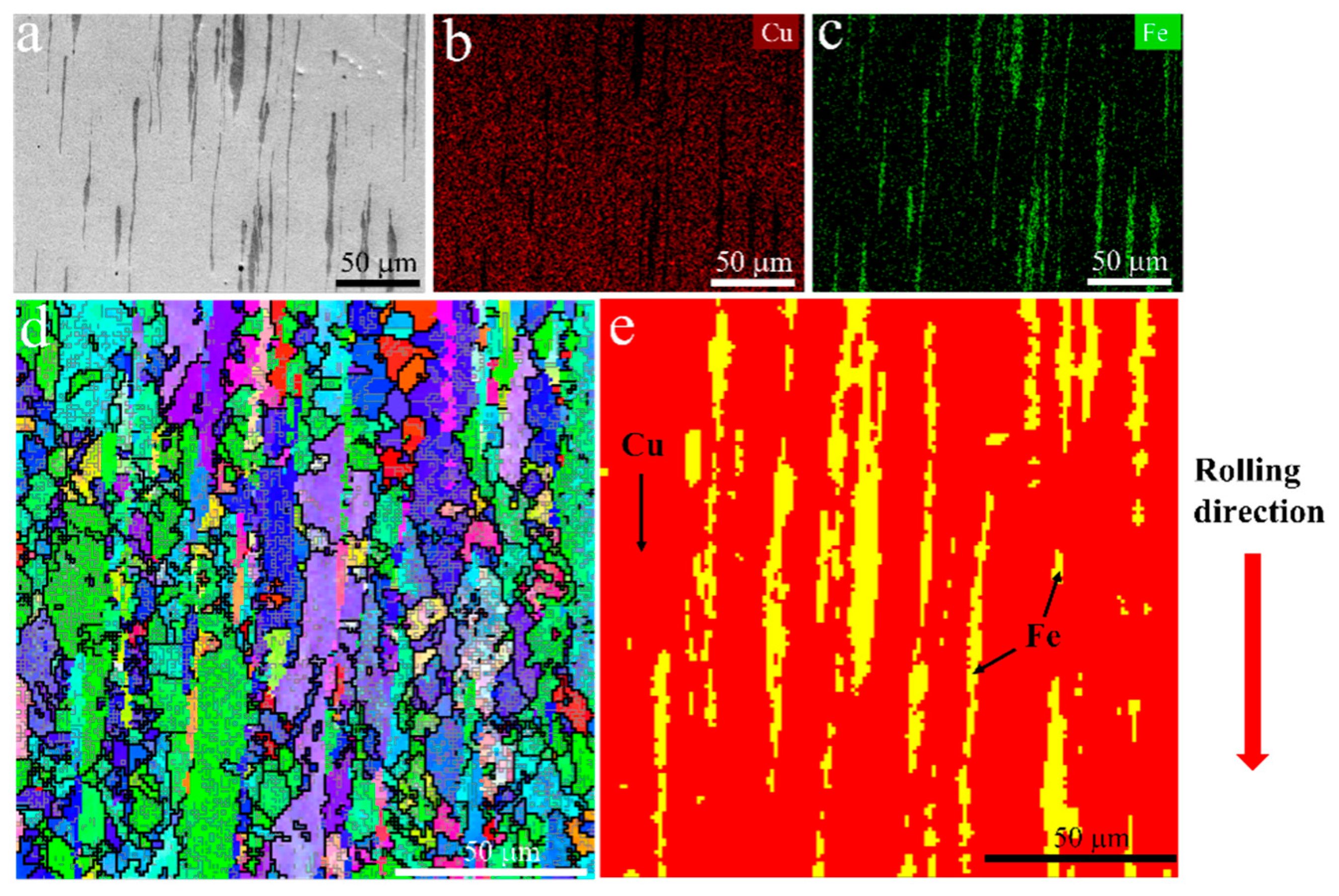
Figure 1. Microstructure of the hot-rolled Cu-10 wt.% Fe plate, (a) backscatter image, (b) distribution of Cu element, (c) distribution of Fe element, (d) inverse pole figure (IPF) map, and (e) phase distribution.
Metals 13 01304 g001
Figure 2. Microstructure of ultrasonic surface rolling processed (USRPed) Cu-Fe plate, (a) schematic showing ultrasonic surface rolling process, (b) backscatter image showing the cross-sectional microstructure, (c) bright-filed TEM image of the topmost surface layer, and (d) corresponding SAED patterns of c.
Metals 13 01304 g002
Figure 3. Three-dimensional images of surface morphology, (a) initial Cu-Fe plate, and (b) ultrasonic surface rolling processed Cu-Fe plate.
Metals 13 01304 g003
Figure 4. (a) Schematic diagram of the gradient structure and (b) micro-hardness evolution with distance away from the surface.
Metals 13 01304 g004
Figure 5. True stress–strain curves of the hot-rolled plate (initial) and the USRPed plate.
Metals 13 01304 g005
Figure 6. Potential dynamic polarization curves of USRPed plate and the initial plate in 3.5 wt.% NaCl solution.
Metals 13 01304 g006
Figure 7. Electrochemical impedance spectroscopy (EIS) spectra of USRPed plate and the initial plate in 3.5 wt.% NaCl solution; (a) Bode impedance; (b) Nyquist impedance spectra; insert shows the equivalent circuit model.
Metals 13 01304 g007
Figure 8. Variation in yield strength with micro-hardness of this work and the reported data from [4,25,26].
Metals 13 01304 g008
Figure 9. Microstructure of samples after immersion in 3.5 wt.% NaCl solution (ad) for 1, 3, 5 and 7 days of USRPed Cu-Fe plate, and (eh) for 1, 3, 5 and 7 days of initial Cu-Fe plate.
Metals 13 01304 g009
Figure 10. Three-dimensional images of the corrosion morphology after immersion for 28 days of (a) initial Cu-10Fe plate and (b) USRPed Cu-10Fe plate.
Metals 13 01304 g010
Figure 11. In situ microstructure evolution of the initial Cu-Fe plate during polarization: (a) before polarization; (b) t = 300 s; (c) t = 340 s.
Metals 13 01304 g011
Table 1. Yield strength, ultimate strength, and uniform elongation of the hot-rolled (initial) plate and the USRPed plate.
Yield StrengthUltimate StrengthUniform Elongation
Initial297 MPa504 MPa19.1%
USRPed378 MPa500 MPa14.6%
Table 2. Corrosion parameters of USRPed plate and the initial plate in 3.5 wt.% NaCl solution. E c o r r is the corrosion potential, and i c o r r is the corrosion current density. β c and β a are the cathode and anode slopes. R p is the polarization resistance.
SpecimenEcorr (VSCE)icorr (μA/cm2)βa (mV)βc (mV)Rp (Ω·cm2)Chi-Square
Initial−0.39611.405176.5888.30.560.01
USRPed−0.2723.238117.3289.11.130.017
Table 3. Electrochemical impedance parameters of USRPed plate and the initial plate in 3.5 wt.% NaCl solution.
SpecimenRs (Ω·cm2)CPEdlRct (Ω·cm2)Chi-Square
Q (F cm−2 sn−1)n
Initial26.646.07 × 10−40.8231320.021
USRPed30.431.73 × 10−40.7368060.011
Disclaimer/Publisher’s Note: The statements, opinions and data contained in all publications are solely those of the individual author(s) and contributor(s) and not of MDPI and/or the editor(s). MDPI and/or the editor(s) disclaim responsibility for any injury to people or property resulting from any ideas, methods, instructions or products referred to in the content.