Abstract
The effects of partial replacement of Si by Al on the microstructure, tensile properties, and Charpy impact toughness were investigated using 0.2%C-Si/Al-Mn-Cr-B TRIP-aided martensitic steels to promote the application of galvanized third-generation ultrahigh- and high-strength steels. The impact toughness was related to the microstructural and mechanical properties. The partial replacement decreased the volume fraction of retained austenite and increased the mechanical stability, accompanied by softening and an increase in the volume fraction of the primary martensite. Resultantly, the partial replacement decreased strength and ductility. The impact absorbed energy (value) at 25 °C was slightly increased by the partial replacement. The increased impact absorbed energy was mainly caused by high crack/void propagation energy due to the softened primary martensite and a small contribution of the stabilized retained austenite. The 50% shear fracture ductile-to-brittle transition temperature was marginally raised by the partial replacement. The raised transition temperature was mainly associated with an increase in a unit crack path of quasi-cleavage/cleavage fracture.
1. Introduction
The third-generation advanced ultrahigh- and high-strength steels (AHSSs) have been developed for automotive applications as sheet-forming components and bar-forging parts [1,2,3,4]. The AHSSs are classified into the following two groups, “Group I” and “Group II”, by the kind of matrix structure and/or tensile strength level [4], as follows.
Group I: TRIP-aided bainitic ferrite (TBF) steel [5,6], one-step and two-step quenching and partitioning (Q&P) steels [7,8,9,10,11], carbide-free bainitic (CFB) steel [12,13,14,15], and duplex type, laminate type, and Q&P-type medium manganese steels (D-MMn [16,17,18,19,20,21,22], L-MMn [23], and Q&P-MMn [24,25] steels),
Group II: TRIP-aided martensitic (TM) steel [26,27,28,29] and martensite-type medium manganese (M-MMn) steel [24,30,31].
Group I steels have a tensile strength lower than 1 GPa and/or a bainitic ferrite structure (or a mixed structure of bainitic ferrite and martensite). Group II steels have a tensile strength higher than 1.5 MPa and a harder complex structure of the primary tempered martensite (αm) and the secondary fresh martensite-retained austenite (MA; αm* + γR) phase. The mechanical properties of the Group I and Group II steels are characterized by excellent cold formability, impact toughness, fatigue strength, hydrogen embrittlement properties, etc. [4,27,32,33]. These excellent mechanical properties are mainly brought from the transformation-induced plasticity (TRIP) [34] of metastable retained austenite or reverted austenite and the complex phase structure.
In the various first- and third-generation AHSSs, microalloying elements such as C, Si, Al, Mn, Cr, Mo, Ni, B, Nb, Ti, V, etc. are added to increase the various mechanical properties through the microstructural improvement [35,36,37,38,39,40]. Al is mainly added as an alternative element to Si. This is because, not only is Al a ferrite stabilizer similar to Si, but it is also insoluble in carbide [41]. Another advantage of Al over Si is a high driving force from austenite to bainite which accelerates the bainite transformation kinetics resulting from an increased nucleation rate [41,42,43]. This becomes especially advantageous for industrial production in conventional galvanizing lines with overaging sections. Fortunately, Al does not degrade the coatability (or galvanizing) adversely, unlike Si, because the partial replacement of Si by Al disturbs the formation of amorphous oxide [42]. Thus, Al is mainly added as an alternative element to Si in the AHSSs like P [40]. Al also remarkably increases the maximum carbon concentration of retained austenite by raising the critical temperature (T0) at which austenite and martensite have the same Gibbs free energy in steel [39]. This is because Al retards the carbide formation and resultantly increases the volume fraction of retained austenite like Si and P [4,40,44,45,46].
To promote the application of galvanized third-generation low-carbon AHSS sheets and bars to automotive parts, many researchers investigated the effect of partial replacement of Si by Al on the microstructural and mechanical properties [4,35,36,46,47,48,49,50]. Unfortunately, most of the mechanical properties were focused on the tensile properties and formabilities, not impact toughness, in the third-generation AHSSs. This paper investigated the influence of the partial replacement of Si by Al on the microstructure, tensile properties, and Charpy impact toughness using the third-generation 0.2%C-Si/Al-Mn-Cr-B TM sheets of steel belonging to Group II. The impact toughness was compared with those of several third-generation AHSSs such as TBF, TM, D-MMn, and M-MMn steels with different chemical compositions and commercial JIS-SCM420 martensitic steel. In addition, the impact toughness was related to the microstructural properties, as well as the tensile properties.
2. Materials and Methods
Two kinds of steels (Si-Al steels) with different Si and Al contents were prepared in the form of 100 kg slabs by vacuum melting. The total content of Si and Al was kept constant; Al + Si = 1.5 mass% (Table 1). Hereafter, these steels with 0.022 and 1.22 mass% Al are named 0Al and 1.2Al steels, respectively. For comparison, several third-generation AHSSs with different Si, Mn, Cr, Mo, Al, and Nb contents (Cr-Mo TBF and TM steels, Al-Nb TBF and TM steels, and medium Mn (D-MMn and M-MMn) steels) were prepared in this study (Table 1). In addition, commercial martensite steel (JIS-SCM420 steel) subjected to quenching to 25 °C and tempering at 200 °C to 600 °C for 3600 s (Q&T) was used. The slabs of the 0Al and 1.2Al steels were heated to 1200 °C and hot-rolled to 5 mm thickness with a finishing temperature of 850 °C, followed by air-cooling to room temperature. After that, a part of the hot-rolled plates was cold-rolled into sheets of 1.2 mm thickness after ground to a thickness of 3 mm.

Table 1.
Chemical composition (mass%) and measured transformation temperatures (°C) of Si-Al, Cr-Mo, Al-Nb, and MMn steels [5,6,17,24,26,46]. TM, TBF, D-type, M-type, and Q&T represent TRIP-aided martensite, TRIP-aided bainitic ferrite, duplex type MMn, martensite-type MMn, and quenching and tempering martensite steels, respectively.
Tensile specimens (JIS-5, 50 mm gauge length, 12.5 mm width, and 1.2 mm thickness) parallel to the rolling direction were machined from the cold-rolled sheets. Subsized V-notched impact specimens (JIS-4, 55 mm long, 10 mm wide, 2.5 mm thick, 2 mm V-notch) were machined from the hot-rolled plates along the rolling direction. To measure the austenite-finish and -start temperatures (Ac3, Ac1 in °C), and martensite-start and -finish temperatures (Ms and Mf in °C) of both steels, these thermal expansion curves were produced using Thermecmastor-Z (Fuji Electronic Industrial Co., Ltd., Tsuruga-shima, Saitama, Japan). Referring to the curves (Figure 1), the heat treatment shown in Figure 2 was carried out, namely, direct quenching in oil at 200 °C (below Mf) and isothermal transformation (IT) treatment at 200 °C for 1000 s after being austenitized at 1050 °C (above Ac3) for 1200 s. The IT holding time (1000 s) corresponds to the time for which the maximum retained austenite fraction is obtained from preliminary experiments. For Cr-Mo and Al-Nb TBF steels, IT treatment at the temperatures between Ms and Mf was carried out. For Cr-Mo and Al-Nb TM steels, the same heat treatment as Figure 2 was conducted. For the heat treatment of D-MMn and M-MMn steels, please refer to Refs. [17,24].
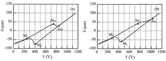
Figure 1.
Thermal displacement-temperature (δ-T) curves of specimens cooled at 30 °C/s after heating to 1150 °C in (a) 0Al and (b) 1.2Al steels.
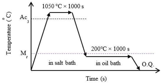
Figure 2.
Heat treatment diagram for 0Al and 1.2Al TM steels. O.Q. is quenching in oil at room temperature.
The microstructure of the steels was observed by field-emission scanning electron microscopy (FE-SEM; JSM-6500F, JEOL Ltd., Akishima, Tokyo, Japan), which was performed using an instrument equipped with an electron backscatter diffraction system (EBSD; OIM system, TexSEM Laboratories, Inc., Prova, UT, USA). The EBSD analysis was conducted in an area of 40 μm × 40 μm with a beam diameter of 1.0 μm and a beam step size of 0.1 μm operated at an acceleration voltage of 25 kV. The specimens for the FE-SEM–EBSD analysis were first ground with alumina powder and colloidal silica and, then, ion-thinning was carried out. The volume fraction of carbide in the specimens was measured by carbon extraction replicas and the FE-SEM technique. The volume fraction of the MA phase (fMA) was estimated from the EBSD image by the line segmentation method.
Retained austenite characteristics of the steels were evaluated by an X-ray diffractometer (RINT2000, Rigaku Co., Akishima, Tokyo, Japan). The surfaces of the specimens were electropolished after being ground with emery paper (#1200). The volume fraction of the retained austenite phase (fγ, vol.%) was quantified from the integrated intensity of the (200)α, (211)α, (200)γ, (220)γ, and (311) γ peaks obtained by X-ray diffractometry using Mo-Kα radiation [51]. The carbon concentration in retained austenite (Cγ, mass%) was estimated from the empirical equation proposed by Dyson and Holmes [52]. To accomplish this, the lattice constant of retained austenite was determined from the (200)γ, (220)γ, and (311)γ peaks of the Cu-Kα radiation. The average values of volume fraction and carbon concentration of retained austenite and other microstructural properties were measured at three locations in the specimen.
Vickers hardness tests were carried out using a Vickers microhardness tester (DUH-201H, Shimadzu Co., Kyoto, Japan) at 25 °C, with a load of 0.98N. Tensile tests were conducted on a tensile testing machine (AD-10TD, Shimadzu Co., Kyoto, Japan) at 25 °C and at a mean strain rate of 2.8 × 10⁻³ s−1 (a crosshead speed: 10 mm/min). Impact tests were performed on conventional and instrumental Charpy impact testing machines (CI-300 and CAI-300, Tokyo Testing Machine Inc., Tokyo, Japan) in a temperature range of −196 °C to +100 °C. Liquid nitrogen, dry ice, ethyl alcohol, and water were used to cool and heat the specimens. The specimens were held at different temperatures for 1800 s before being tested. After that, the impact tests were performed within 3 s after removing the specimen from the temperature-regulating mediums. The impact properties were evaluated by Charpy impact absorbed energy or value (Ev) and 50% shear fracture ductile-to-brittle transition temperature (DBTT). At least three tensile and impact specimens were tested for each condition to obtain the average values of the tensile properties and Ev at 25 °C.
3. Results
3.1. Microstructure
Figure 3 shows various EBSD maps of heat-treated 0Al and 1.2Al TM steels. The microstructures consist of primary martensite, retained austenite, and MA phase (Figure 3a–f). The primary martensite is divided into two kinds of martensite, namely a soft-type martensite (“type S”) with an image-quality (IQ) index higher than 100 and a hard-type martensite (“type H”) with an IQ index of 40 to 100 (Figure 3e–h). Note that the IQ indices of the primary type S and type H martensites in the 1.2Al TM steel are higher than that in 0Al TM steel (Figure 3e–h). In addition, the volume fraction of type S martensite is higher than that of the 0Al steel. On the other hand, the type H martensite fraction tends to be less than that of the 0Al TM steel (Figure 3e–h).
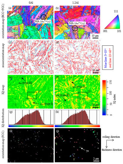
Figure 3.
(a,b) Orientation maps of BCC (alpha) and FCC (gamma) phases, (c,d) grain/lath boundary misorientation maps of BCC phase, (e,f) image quality (IQ) distribution maps of BCC phase, (g,h) IQ distribution, and (i,j) orientation maps of FCC in 0Al and 1.2Al TM steels. (i,j) are high magnifications in rectangles of (e,f), respectively. αm, αm*, MA, and γR represent primary martensite, secondary martensite, MA phase, and retained austenite, respectively.
The MA phase fraction (fMA) of the 1.2Al TM steel is nearly the same as that of the 0Al TM steel (Table 2). The size of the secondary martensite in the MA phase of both sheets of steel is nearly the same (Figure 3a,b). In this research, the secondary martensite possesses an IQ index lower than 40, although the IQ index of the secondary martensite of 1.2Al TM steel is higher than that of 0Al TM steel (Figure 3g,h). Many fine retained austenites seem to be located in the MA phase and along the lath, block, and packet boundaries of the primary martensite (Figure 3i,j). It is noteworthy that the retained austenite size of the 1.2Al steel is larger than that of the 0Al steel.
Table 2.
Microstructural properties of 0Al and 1.2Al TM steels.
Figure 4 shows SEM images of 0Al and 1.2Al steels. Prior austenitic grain size (d) is nearly the same in the steels (Table 2). There is a small amount of fine carbide (θ) only in the primary martensite of the 1.2Al TM steel (Figure 4c), in the same way as the 0Al steel.
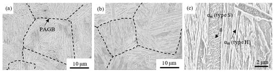
Figure 4.
SEM images of (a) 0A and (b) 1.2Asteels. (c) is a high magnification of a certain region of 1.2Al steel, showing two types of primary martensite (αm) and carbide (θ). PAGB is the prior austenitic grain boundary.
Many of the carbides precipitate in the primary type S martensite. These carbide fractions (fθ) are about 1 vol.% (Table 2) and are nearly the same as those previously reported for Cr-Mo TM steels [26,53]. The carbide is supposed to be the transition carbide or η-carbide [54]. Vickers hardness (HV428) of the 1.2Al TM steel is lower than that (HV473) of the 0Al TM steel (Table 3).
Table 3.
Vickers hardness, tensile properties, and impact properties of 0Al and 1.2Al TM steels.
The initial volume fraction of retained austenite (fγ0) is decreased and its initial carbon concentration (Cγ0) is increased by the partial replacement of Si by Al (Table 2). The initial total carbon concentration of retained austenite (fγ0 × Cγ0) of the 1.2Al TM steel is slightly higher than that of the 0Al TM steel (Table 2).
The strain-induced transformation factor (k) is defined by the following equation, meaning the mechanical stability of retained austenite [4],
where fγ is the retained austenite fraction after plastically strained to εT. The k-value of the 1.2Al TM steel is slightly lower than that of the 0Al TM steel (Table 2).
k = (ln fγ0 − ln fγ)/εT
3.2. Tensile Properties
Engineering stress−strain (σ−ε) curves and instantaneous strain hardening exponent–true strain (n−εT) curves of the 0Al and 1.2Al TM steels are shown in Figure 5. The tensile properties are shown in Table 3. Partial replacement of Si by Al considerably reduces the flow stress and the instantaneous n value. Resultantly, the yield stress (YS), tensile strength (TS), uniform (UEl), and total elongations (TEl) are decreased by the partial replacement, although the reduction of area (RA) is increased.
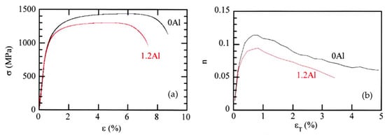
Figure 5.
(a) Typical engineering stress–strain (σ−ε) curves and (b) instantaneous strain hardening exponent–true strain (n−εT) curves of 0Al and 1.2Al TM steels.
Figure 6 shows the relationship between TS and TEl of the 0Al and 1.2Al TM steels. The product of TS and TEl (TS × TEl) of the 1.2Al TM steel is lower than that of 0Al TM steel. The TS × TEl is lower than those of Cr-Mo TM steels and SCM420 Q&T steel. Notably, it is much lower than those of Cr-Mo and Al-Nb TBF steels and D-MMn and M-MMn steels.
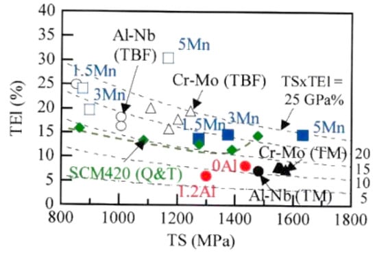
Figure 6.
Combination of the tensile strength (TS) and total elongation (TEl) of 0Al and 1.2Al TM steels (●), Cr-Mo TBF (△, TIT = Ms − Mf) [5] and TM steels (▲) [26], Al-Nb TBF (○, TIT = Ms − Mf)) [46] and TM (●) steels [55], D-MMn (□) [17] and M-MMn (■) [24] steels with 1.5%Mn, 3%Mn, and 5%Mn, and SCM420 Q&T steel (◆, TT = 200 °C to 600 °C) [5,26].
3.3. Impact Toughness
Figure 7 shows the testing temperature dependence of the Ev in the 0Al and 1.2Al TM steels. The upper shelf Ev of the 1.2Al TM steel is slightly higher than that of the 0Al TM steel. In this case, the upper shelf Evs of the 0Al and 1.2Al TM steels are approximately equal to the Evs obtained at 25 °C. The DBTT of the 1.2Al TM steel is −85 °C and slightly higher than that (−94 °C) of the 0Al TM steel (Table 3).
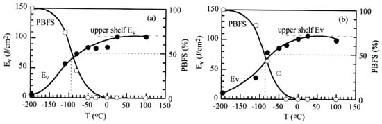
Figure 7.
Variations in Charpy impact absorbed energy or value (Ev) and percent of brittle fracture surface (PBFS) with testing temperature (T) in (a) 0Al and (b) 1.2Al TM steels.
Figure 8 shows the impact load-displacement (P-δ) curves of the 0Al and 1.2Al TM steels obtained by instrumental Charpy impact tests at 25 °C. It is found that the 1.2Al TM steel has lower crack/void initiation energy or value (Ei) and higher crack/void propagation energy or value (Ep) than the 0Al TM steel.
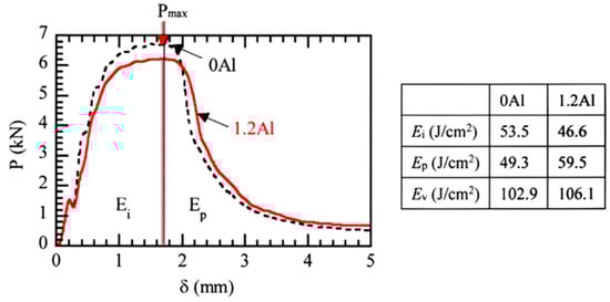
Figure 8.
Impact load-displacement (P−δ) curves measured by instrumented Charpy impact tests at 25 °C in 0Al and 1.2Al TM steels. Ei: crack/void initiation energy or value, Ep: crack/void propagation energy or value, Ev: Charpy impact absorbed energy or value (Ev = Ei + Ep). Arrows denote the maximum impact load (Pmax).
Figure 9 shows the relationships between TS and Ev at 25 °C and between TS and DBTT of the 0Al and 1.2Al TM steels, which are compared with those of other third-generation AHSSs. The product of TS and Ev (TS × Ev) at 25 °C is hardly changed by the partial replacement of Si by Al (Figure 9a). The TS × Evs of the 0Al and 1.2Al TM steels are lower than those of Cr-Mo TBF and TM steels, Al-Nb TBF steels, and M-MMn steels, although they are far higher than those of SCM420 Q&T steel tempered at 200 °C to 600 °C. The product of TS and DBTT (TS × DBTT) of the 1.2Al TM steel is slightly higher than that of the 0Al TM steel (Figure 9b). It is much higher than those of Cr-Mo TM steels, but also it is much lower than those of D-MMn steels, Cr-Mo and Al-Nb TBF steels, and SCM420 Q&T steel tempered at 300 °C to 600 °C.
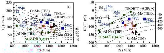
Figure 9.
(a) Relationship between tensile strength (TS) and Charpy impact absorbed energy or value (Ev) at 25 °C and (b) relationship between TS and 50% shear fracture ductile-to-brittle transition temperature (DBTT) in 0Al and 1.2Al TM steels (●), Cr-Mo TBF (△, TIT = Ms − Mf) [5] and TM steels (▲) [26], Al-Nb TBF steels (○, TIT = Ms − Mf)) [6], D-MMn (□) [17] and M-MMn (■) [24] steels with 1.5%Mn, 3%Mn, and 5%Mn, and SCM420 Q&T steel (◆, TT = 200 to 600 °C) [5,26,27].
Figure 10 shows typical SEM images of impact-fracture surfaces of the 0Al and 1.2Al TM steels tested at 25 °C and −196 °C. The impact-fracture surfaces show typical ductile and brittle fractures, respectively. The ductile-fracture surface of 0Al TM steel consists of coarse and fine dimples. The coarse dimple path of the 0Al TM steel is nearly equivalent to the MA phase path. This fact means that a part of the coarse dimples initiates at the interface between the MA phase and the primary martensite. Note that the dimples on the fracture surface of the 1.2Al TM steel are finer, flatter, and more uniform than those of the 0Al TM steel. The dimpled area of the 1.2Al TM steel is equivalent to the prior austenitic grain one. In this case, the MA phase hardly contributes to initiating the coarse dimple. The effect of the MA phase on dimple fracture should be investigated in detail in the future because the dimple fracture is also affected by the morphology, size, and distribution of the MA phase.
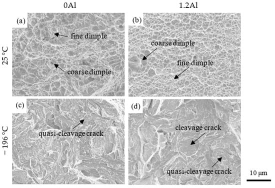
Figure 10.
Typical SEM images of the impact-fracture surface of 0Al and 1.2Al TM steels tested at 25 °C and −196 °C. (a,b) ductile (shear) fracture, (c,d) brittle (cleavage and/or quasi-cleavage) fracture.
The fracture surface tested at −196 °C of the 1.2Al TM steel is mixed by quasi-cleavage fracture with river pattern and cleavage fracture without river pattern, differing from that (only quasi-cleavage fracture) of the 0Al TM steel. It is noteworthy that the 1.2Al TM steel has a larger unit crack path (LC) on the cleavage and quasi-cleavage fracture surface, compared with the 0Al TM steel (Table 3).
4. Discussion
4.1. Primary Martensite and Retained Austenite Characteristics
First, the effect of the partial replacement of Si by Al on the softened primary martensite is discussed. In this study, the primary martensite (type S and type H) of the 1.2Al TM steel was characterized by a higher IQ index than that of 0Al TM steel (Figure 3e–h). In addition, the type S martensite fraction was higher than that of the 0Al TM steel. In general, the IQ index is mainly controlled by alloying element concentration and dislocation density in the structure. The total carbon concentration of retained austenite (fγ0 × Cγ0) was slightly higher than that of 0Al TM steel (Table 2). As the volume fraction of carbide in the 1.2Al TM steel was nearly the same as that in the 0Al TM steel, the carbon concentration of the primary martensite is estimated to be lower than that of the 0Al steel. The solid-solution hardening of Al (24 MPa/at.%) is about half that of Si (55 MPa/at.%) in Fe-C steel [56]. Therefore, the higher IQ index of the primary martensite of the 1.2Al TM steel may be associated with lower C and Si concentrations (or lower solid-solution hardening) and lower dislocation density (or lower dislocation hardening). Higher Ms of the 1.2Al steel may also contribute to a higher IQ index or softening of the primary martensite.
Next, the initially retained austenite characteristics of the 1.2Al TM steel are discussed. In this study, the initial carbon concentration of retained austenite (Cγ0 = 0.54 mass%) of the 1.2Al TM steel was higher than that (0.36 mass%) of the 0Al TM steel, although the volume fraction (fγ0 = 3.5 vol%) was lower than that (4.3 vol.%) of the 0Al TM steel, as shown in Table 2. Such a result has been already reported by Imai et al. [46] and Sugimoto et al. [55], who investigated the effect of Al content on the retained austenite characteristics in the first-generation 0.2%C-2%Si-1.5%Mn and 0.2%C-2%Al-1.5%Mn TRIP-aided polygonal ferrite (TPF) steels and 0.2%C-(0.5–1.5)%Si-1.5Mn-(0.038–1.0)%Al TPF and TRIP-aided annealed martensitic (TAM) steels, respectively. Tian et al. [48] and Kaar et al. [38] also reported similar results in 0.22%C-1.82%Si-2.04%Mn-1.02%Cr-0.50%Al CFB steel and 0.2%C-1.5%Si/Al-4.0%Mn Q&P steel, respectively. They proposed that the increased carbon concentration is caused by the increased T0 temperature. As an example, T0 temperature calculated in terms of Thermo-Calc for Fe-C-1.5Si-1.5Mn and Fe-C-0.5Si-1.5Mn-1.0Al steels is shown in Figure 11 [55]. Note that the carbon concentrations of retained austenite (Table 2) in the 0Al and 1.2Al TM steels are very low compared with that at the T0 temperature shown in Figure 11. This characteristic is a typical feature of TM steel because of insufficient carbon enrichment during the IT process at the low temperature after direct quenching, which leads to a large amount of MA phase [57].
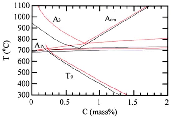
Figure 11.
Phase diagram and T0 temperature calculated in terms of Thermo-Calc for Fe-C-1.5Si-1.5Mn (black lines) and Fe-C-0.5Si-1.5Mn-1.0Al (red lines) steels [55].
Figure 12 shows the relationship between the k-value and Cγ0 in various third-generation AHSSs including the 0Al and 1.2Al TM steels. In the 0Al and 1.2Al TM steels and Cr-Mo TM steels, the k-values decrease with increasing Cγ0. However, the k-values are much higher than those of Cr-Mo and Al-Nb TBF steels. This may be principally associated with the high flow stress of the matrix structure and lower Cγ0. It can be expected that further addition of 0.05% Nb to the 1.2Al TM steel can be very effective in increasing the volume fraction and carbon concentration of retained austenite by refining the prior austenitic grain as reported for 0.2C-1.0Si-1.5Mn-0.5Al-0.05Nb TBF and TM steels [46,58]. As shown in Figure 3i,j, the retained austenite size of the 1.2Al steel was larger than that of the 0Al steel. The increased size does not apparently seem to influence the k-value.
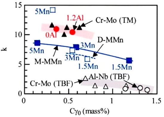
Figure 12.
Relationship between k-value and initial carbon concentration of retained austenite (Cγ0) in 0Al and 1.2Al TM steels (●), D-MMn (□) [17] and M-MMn (■) [24] steels with 1.5%Mn, 3%Mn, and 5%Mn, Cr-Mo TBF (△, TIT = Ms − Mf) [5] and TM steels (▲) [26], and Al-Nb TBF steels (○, TIT = Ms − Mf) [6].
4.2. Relationship between Tensile and Microstructural Properties
According to Sugimoto et al. [4,33], true flow stress (true plastic strain), σT(εT), of the AHSS containing the retained austenite of from 4 to 30 vol.% is formulated by
where σM (εT) and Δσh (εT) are the flow stress of the matrix structure and strain-hardening increment of the steel, respectively. The Δσh (εT) can be estimated by
where Δσi (εT), Δσt (εT), and Δσf (εT) represent “the long-range internal stress hardening”, “the strain-induced transformation hardening”, and “the forest dislocation hardening” [59], respectively, which can be formulated by
where ν is the Poisson’s ratio, μ is the shear modulus, εpu is “the eigenstrain” [60], f is the volume fraction of the second phase, g (Δfαm) is a function of the strain-induced martensite fraction, ζ is a material constant, b is the Burgers vector, and r is particle radius of the second phase.
σT(εT) = σM (εT) + Δσh (εT)
Δσh (εT) = Δσi (εT) + Δσt (εT) + Δσf (εT)
Δσi (εT) = {(7 − 5ν)μ/5(1 − ν)} f · εpu
Δσt (εT) = g (Δfαm)
Δσf (εT) = ζμ (b · f · εT/2r)1/2,
Kobayashi et al. [26] and Sugimoto et al. [33] proposed that the MA phase mainly contributes to “the long-range internal stress hardening”, with a small contribution to “the strain-induced transformation hardening” by a small quantity of retained austenite in the Cr-Mo TM steels. The matrix structure (primary martensite) in the 1.2Al TM steel was supposed to have lower “solid solution hardening” and “forest dislocation hardening”, compared to that of the 0Al TM steel. As the 1.2Al TM steel has nearly the same volume fraction of MA phase as the 0Al TM steel (Table 2), the low flow stress and n value are considered to be mainly associated with lower flow stress of the matrix (primary martensite) due to a higher Al concentration (or lower Si concentration) and a lower retained austenite fraction than those of the 0Al TM steel. Naturally enough, the low n-value results in small UEL and TEl. The long-range internal stress hardening increases the flow stress and n value, but the contribution is considered to be relatively small, compared to the negative contribution of the solid-solution hardening, in the 1.2Al steel. According to Sugimoto et al. [57] and Pham et al. [53], the volume fraction of carbide hardly influences the tensile properties of low-carbon TM steels because it is a very small quantity.
As shown in Figure 13a, the TS × TEl increases with increasing the initial volume fraction of retained austenite in the 0Al and 1.2Al TM steels, Cr-Mo TBF and TM steels, Al-Nb TBF steels, and D-MMn and M-MMn steels. In addition, it increases with decreasing k-value (or increasing mechanical stability of retained austenite) except for those of D-MMn and M-MMn steels (Figure 13b). Therefore, a decrease in TS × TEl of the 1.2Al TM steel may be caused by the decreased retained austenite fraction (or the decreased strain-induced transformation hardening), as well as the low flow stress. As shown in Figure 13b, the TS × TEls of D-MMn and M-MMn steels are much larger than those of Cr-Mo TM and Cr-Mo and Al-Nb TBF steels under the same k-value. This indicates that the initially retained austenite fraction dominantly contributes to the TS × TEl in the D-MMn and M-MMn steels because they linearly increase with the initial volume fraction of retained austenite. Such a mechanism is different from one of the Cr-Mo and Al-Nb TBF steels, in which high TS × TEls are brought from the bainitic ferrite structure matrix and a large amount of volume fraction and high mechanical stability of retained austenite.
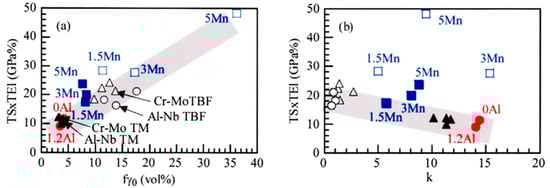
Figure 13.
(a) TS × TEl-fγ0 and (b) TS × TEl-k-value relations in 0Al and 1.2Al TM steels (●), D-MMn (□) [17], and M-MMn (■) [24] steels with 1.5%Mn, 3%Mn and 5%Mn, Cr-Mo TBF (△, TIT = Ms − Mf) [5] and TM steels (▲) [26], and Al-Nb TBF (○, TIT = Ms − Mf) [46] steel.
Unfortunately, the TS × TEl of the 1.2Al TM steel was reduced compared to that of the 0Al TM steel (Figure 6 and Figure 13). However, it can be enhanced by further addition of 0.05 mass% Nb which refines the prior austenitic grain size and increases the initial retained austenite fraction [58]. As with the other microalloying elements, the complex addition of Cr and P is also recommended because these elements increase the hardenability [26] and the solid solution hardening [40], respectively.
4.3. Relationship between Impact Toughness and Microstructural Properties
4.3.1. Ev at 25 °C (Upper shelf Ev)
Kobayashi et al. proposed the ductile fracture mechanism of Cr-Mo TM steels subjected to the impact test (Figure 14a) [26]. According to them, (i) a softer primary martensite matrix structure, (ii) a larger amount of stable retained austenite, and (iii) a moderate amount, hardness, and size of the MA phase increase the Ev. In this case, most of the deep voids originate at the interface of the MA phase and the primary martensite. Thus, the MA phase plays a role in forming the coarse dimples and resultantly suppressing the void connection by fine dimples. Fine and filmy retained austenite in the MA phase suppresses the void formation through the relaxation of localized stress concentration on train-induced martensite transformation. The ductile fracture of the 0Al TM steel was followed by the ductile fracture mechanism shown in Figure 14a.
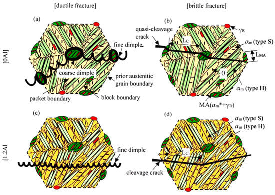
Figure 14.
Illustration showing (a,c) ductile fracture and (b,d) brittle fracture of 0Al and 1.2Al TM steels appeared after impact tests. LC, LMA, αm, αm*, MA, θ, and γR represent a unit crack path of the cleavage or quasi-cleavage fracture, MA phase size, primary martensite, secondary martensite, MA phase, carbide, and retained austenite, respectively. (a,b) are modified on the basis of Ref. [26].
The 1.2Al TM steel exhibited a ductile fracture surface with finer, flatter, and more uniform dimples (Figure 10b). In addition, the fine dimple area was equivalent to the prior austenitic grain size. The microstructure of the 1.2Al TM steel was characterized as follows.
- ●
- ●
- The primary martensite was softened in comparison with that of 0Al TM steel. The volume fraction of the primary type S martensite increased compared to the 0Al TM steel, with a decrease in the primary type H martensite fraction (Figure 3e−h);
- ●
- The secondary martensite was also softened in comparison with that of 0Al TM steel (Figure 3g,h).
From these facts, the ductile fracture behavior of the 1.2Al TM steel can be illustrated as shown in Figure 14c. Namely, fine dimples mainly initiate in the primary type S martensite and pass through the primary type S and type H martensite. In this case, the MA phase hardly contributes to the dimple fracture, different from the 0Al TM steel. As shown in Figure 8, the 1.2Al TM steel exhibited a lower Ei and a higher Ep than 0Al TM steel. Thus, the low Ei of the 1.2Al TM steel may be caused by the void formation in the primary martensite with low flow stress. On the other hand, the high Ep may be related to the difficult void connection passing through the primary type S and the type H martensite.
Next, the role of retained austenite characteristics on the Ev at 25 °C is discussed. Figure 15 shows the relationships between the TS × Ev and fγ0 and the TS × Ev and k-value in the various third-generation AHSSs including the 0Al and 1.2Al TM steels. The TS × Evs of the 0Al and 1.2Al TM steels and the other third-generation AHSSs increase with increasing fγ0 and decreasing k-value (or increasing mechanical stability of retained austenite). This indicates that an increase in the retained austenite fraction increases the Ev of the 1.2Al TM steel through the relaxation of stress concentration by the strain-induced martensite transformation in the same way as the 0Al TM steel and the conventional third-generation AHSSs. However, the contribution is relatively small because of the small quantity of retained austenite, compared with the high contribution of the softened primary martensite.
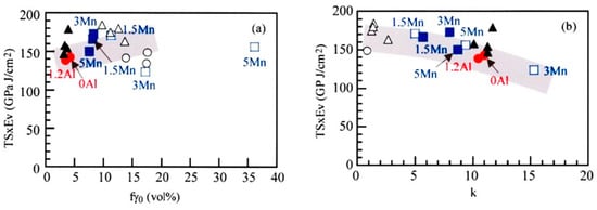
Figure 15.
(a) TS × Ev−fγ0 and (b) TS × Ev−k-value relations in 0Al and 1.2Al TM steels (●), D-MMn (□) [17] and M-MMn (■) [24] steels with 1.5%Mn, 3%Mn, and 5%Mn, Cr-Mo TBF (△, TIT = Ms − Mf) [5] and TM steels (▲) [26], and Al-Nb TBF steels (○, TIT = Ms − Mf) [6].
4.3.2. DBTT
According to Kobayashi et al. [26], the DBTTs of Cr-Mo TM steels are also lowered by (i) a softer primary martensite matrix structure, (ii) a larger amount of stable retained austenite, and (iii) a moderate amount, hardness, and size of MA phase in the same way as a ductile fracture. A role in the (iii) is particularly important to decrease the DBTT of the TM steel, compared with the TBF, Q&P, and CFB steels, because a large amount of relatively hard and large MA phase decreases the LC of quasi-cleavage crack and consequently suppresses the quasi-cleavage crack initiation and propagation in the TM steel (Figure 14b). The brittle fracture behavior of the 0Al steel obeys this mechanism because the MA phase played in decreasing the LC of the quasi-cleavage crack (Table 3).
Kunitake et al. [61] proposed that the DBTT is correlated with the LC, as given by the following equation, in (0.15–0.25)%C-(0.25–0.30)%Si-(1.0–2.5)%Mn-(0.5–1.0)%Cr-0.5%Mo-(0–0.0023)%B steels with the microstructures of bainitic and martensitic structure and tempered bainitic/martensitic structure. In this case, the tempered bainitic/martensitic steels exhibited lower DBTTs than the bainitic and martensitic steels.
DBTT ∝ − ln LC−1/2.
Figure 16 shows the DBTT and LC−1/2 relation in various third-generation AHSSs, including the 0Al and 1.2Al TM steels. In the figure, lines (1) and (2) show the DBTTs of the above-mentioned bainitic/martensitic steels and tempered bainitic/martensitic steels, respectively [61]. The DBTT of the 1.2Al TM steel is on line (2), although the DBTT of the 0Al TM steel is between lines (1) and (2). Thus, the high DBTT of the 1.2Al TM steel may be mainly caused by the increased LC, although the above (i) and (ii) also play a role in lowering the DBTT. As shown in Figure 3e–h, the primary martensite of the 1.2Al TM steel was softened, compared to the 0Al TM steel. The softened primary martensite may change a part of the quasi-cleavage fracture (Figure 10c) into the cleavage fracture (Figure 10d). Resultantly it plays a role in increasing the LC. In this case, a role in the MA phase to disturb the crack propagation may be relatively small because the cleavage crack mainly initiates in the primary type S martensite and avoids passing through the MA phase. A small amount of stabilized retained austenite may play a role in lowering the DBTT, as reported by Kobayashi et al. [26]. The DBTT of the 1.2Al TM steel was much lower than those of 3Mn and 5Mn D-MMn and M-MMn steels (Figure 16). This may be associated with the higher mechanical stability of retained austenite and the cleavage fracture stress of the 1.2Al TM steel [17,24].
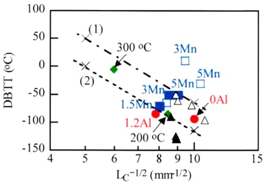
Figure 16.
Relationship between 50% shear fracture ductile–brittle transition temperature (DBTT) and a unit crack path (LC) of the quasi-cleavage fracture in 0Al and 1.2Al TM steels (●), Cr-Mo TBF (△, TIT = Ms − Mf) [5] and TM (▲) [26] steels, D-MMn (□) [17] and M-MMn (■) [24] steels with 1.5%Mn, 3%Mn, and 5%Mn, and SCM420 Q&T steel (◆, TT = 200 °C and 300 °C) [5,26]. Lines (1) and (2) are DBTT–LC−1/2 ones of (0.15–0.25)%C-(0.25–0.30)%Si-(1.0–2.5)%Mn-(0.5–1.0)%Cr-0.5%Mo-(0–0.0023)%B bainitic/martensitic steels and tempered bainitic/martensitic steels, respectively [61].
Finally, further addition of 0.05% Nb to the 1.2Al TM steel can be expected to enhance the Ev and lower the DBTT in the 1.2Al TM steel because of the refining of prior austenitic grain size and the increase in the retained austenite fraction in 0.2%C-1.0%Si-1.5%Mn-0.5%Al TBF and TM steels [58]. The additional research is waiting.
5. Conclusions
This research investigated the effects of the partial replacement of Si by Al on the microstructure, tensile properties, and impact toughness using 0.2%C-Si/Al-Mn-Cr-B TM steels to promote the application of galvanized third-generation ultrahigh- and high-strength steels. Obtained results are summarized as follows.
- (1)
- The partial replacement of Si by Al decreased the retained austenite fraction and increased the austenite’s mechanical stability. The primary martensite was softened by the partial replacement, although the primary type S martensite fraction was increased with a decrease in the primary type H martensite fraction. The partial replacement hardly changed the volume fractions of the MA phase and carbide;
- (2)
- The partial replacement of Si by Al decreased the YS, TS, UEl, TEl, and TS × TEl. This was mainly associated with the reduced solid-solute hardening of the primary martensite, although the TRIP effect of a small amount of stabilized retained austenite slightly contributed;
- (3)
- The partial replacement of Si by Al slightly increased the Ev at 25 °C or upper shelf Ev, although it hardly changed the TS × Ev. The increased Ev was mainly caused by high crack/void propagation energy due to the softened primary martensite and a small contribution of the stabilized retained austenite, with the decreased crack/void initiation energy. In this case, the MA phase hardly took part in the dimple fracture, differing from the 0Al TM steel;
- (4)
- The partial replacement of Si by Al marginally raised the DBTT. The raised DBTT of the 1.2Al TM steel may be mainly caused by the increased LC due to the existence of cleavage fracture resulting from the softened primary martensite and crack pathways avoiding the MA phase.
Author Contributions
Conceptualization, K.-i.S. and J.K.; methodology, K.-i.S., Y.N., J.K., and T.H.; formal analysis, K.-i.S., Y.N., and J.K.; investigation, Y.N., J.K., and T.H.; resources, K.-i.S. and J.K.; data curation, K.-i.S., Y.N., J.K., and T.H.; writing—original draft preparation, K.-i.S. and Y.N.; writing—review and editing, K.-i.S., Y.N. and J.K.; visualization, Y.N. and T.H.; supervision, K.-i.S. and J.K.; All authors have read and agreed to the published version of the manuscript.
Funding
This research received no external funding.
Data Availability Statement
Not applicable.
Conflicts of Interest
The authors declare no conflict of interest.
Nomenclature
| AHSS | advanced high-strength steel | TRIP | transformation-induced plasticity |
| TBF | TRIP-aided bainitic ferrite | Q&P | quenching and partitioning |
| CFB | carbide-free bainite | TM | TRIP-aided martensite |
| D-MMn | duplex type medium Mn | L-MMn | laminate type medium Mn |
| Q&P-MMn | Q&P type medium Mn | M-MMn | martensite type medium Mn |
| TPF | TRIP-aided polygonal ferrite | TAM | TRIP-aided annealed martensite |
| IT | isothermal transformation | Ac3 | austenite-finish temperature |
| Ac1 | austenite-start temperature | Ms | martensite-start temperature |
| Mf | martensite-finish temperature | T0 | critical temperature |
| TIT | IT temperature | TT | tempering temperature |
| γR | retained austenite | αm | primary martensite |
| αm* | secondary martensite | MA | complex phase of αm* and γR |
| θ | carbide | fγ0 | initial volume fraction of γR |
| fγ | The volume fraction of γR | fαm | primary martensite fraction |
| fMA | MA phase fraction | fθ | carbide fraction |
| PAGB | prior austenitic grain boundary | d | prior austenitic grain size |
| Cγ0 | initial carbon concentration of γR | Cγ | carbon concentration of γR |
| k | strain-induced transformation factor (meaning mechanical stability) | ||
| σ | engineering stress | ε | engineering strain |
| σT | true flow stress of steel | εT | plastic strain |
| σM | flow stress of matrix | Δσh | strain hardening increment |
| Δσi | long-range internal stress | Δσt | transformation hardening |
| Δσf | forest dislocation hardening | ν | Poisson’s ratio |
| μ | shear modulus | f | volume fraction of the second phase |
| εpu | eigenstrain | Δfαm | strain-induced martensite fraction |
| ζ | material constant | b | Burgers vector |
| r | particle radius of second phase | YS | yield stress |
| TS | tensile strength | UEl | uniform elongation |
| TEl | total elongation | RA | reduction of area |
| HV | Vickers hardness | n | strain hardening exponent |
| Ev | Charpy impact absolute energy or value (=Ei + Ep) | PBFS | percent of the brittle fracture surface |
| Ei | crack/void initiation energy or value | Ep | crack/void propagation energy or value |
| P | impact load | Pmax | maximum impact load |
| δ | displacement | DBTT | 50% shear fracture ductile-to-brittle transition temperature |
| Lc | unit crack path of quasi-cleavage or cleavage fracture | LMA | size of MA phase |
References
- Rana, R.; Singh, S.B. Automotive Steels—Design, Metallurgy, Processing and Applications; Woodhead Publishing: Cambridge, UK, 2016; pp. 1–469. [Google Scholar]
- Krizan, D.; Steinder, K.; Kaar, S.; Hebesberger, T. Development of third generation advanced high strength steels for automotive applications. In Proceedings of the 19th International Scientific Conference Transfer 2018, Trencin, Slovakia, 22–23 November 2018; pp. 1–15. [Google Scholar]
- Soleimani, M.; Kalhor, A.; Mirzadeh, H. Transformation-induced plasticity (TRIP) in advanced steels: A review. Mater. Sci. Eng. A 2020, 795, 140023. [Google Scholar] [CrossRef]
- Sugimoto, K. Effects of partial replacement of Si by Al on cold formability in two groups of low-carbon third-generation advanced high-strength steel sheet: A review. Metals 2022, 12, 2069. [Google Scholar] [CrossRef]
- Sugimoto, K.; Kobayashi, J.; Ina, D. Toughness of advanced ultra high-strength TRIP-aided steels with good hardenability. In Proceedings of the International Conference on Advanced Steels 2010 (ICAS 2010), Auto Sheet Steels, 9–11 November 2010, Guilin, China; Weng, Y., Dong, H., Gan, Y., Eds.; Metallurgical Industry Press: Beijing, China, 2010. [Google Scholar]
- Hojo, T.; Kajiyama, T.; Sugimoto, K. Impact properties of C-Si-Mn-Al and C-Si-Mn-Al-Nb ultra high-strength low alloy TRIP-aided bainitic ferrite steels. In Proceedings of the Asia Steel 2009, Busan, Republic of Korea, 24 May 2009; pp. S7–S9. [Google Scholar]
- Somani, M.C.; Porter, D.A.; Karjalainen, L.P.; Suikkanen, P.P.; Misra, R.D.K. Process design for tough ductile martensitic steels through direct quenching and partitioning. Mater. Today 2015, 2S, S631–S634. [Google Scholar] [CrossRef]
- Gao, G.; Zhang, H.; Gui, X.; Luo, P.; Tan, Z.; Bai, B. Enhanced ductility and toughness in an ultrahigh-strength Mn-Si-Cr-C steel: The great potential of ultrafine filmy retained austenite. Acta Mater. 2014, 76, 425–433. [Google Scholar] [CrossRef]
- Paravicini Bagliani, E.; Santofimia, M.J.; Zhao, L.; Sietsma, J.; Anelli, E. Microstructure, tensile and toughness properties after quenching and partitioning treatments of a medium-carbon steel. Mater. Sci. Eng. A 2013, 559, 486–495. [Google Scholar] [CrossRef]
- Gao, G.; An, B.; Zhang, H.; Guo, H.; Gui, X.; Bai, B. Concurrent enhancement of ductility and toughness in an ultrahigh strength lean alloy steel treated by bainite-based quenching-partitioning-tempering process. Mater. Sci. Eng. A 2017, 702, 104–112. [Google Scholar] [CrossRef]
- Yang, K.; Li, Y.; Hong, Z.; Du, S.; Ma, T.; Liu, S.; Jin, X. The dominating role of austenite stability and martensite transformation mechanism on the toughness and ductile-to-brittle-transition temperature of a quenched and partitioned steel. Mater. Sci. Eng. A 2021, 820, 141517. [Google Scholar] [CrossRef]
- Keul, C.; Wirths, V.; Bleck, W. New bainitic steel for forgings. Arch. Civ. Mech. Eng. 2012, 12, 119–125. [Google Scholar] [CrossRef]
- Buchmayr, B. Critical assessment 22: Bainitic forging steels. Mater. Sci. Technol. 2016, 32, 517–522. [Google Scholar] [CrossRef]
- Xia, S.; Zhang, F.; Yang, Z. Microstructure and mechanical properties of 18Mn3Si2CrMo steel subjected to austempering at different temperatures below Ms. Mater. Sci. Eng. A 2018, 724, 103–111. [Google Scholar] [CrossRef]
- Qian, L.; Li, Z.; Wang, T.; Li, D.; Zhang, F.; Meng, J. Roles of pre-formed martensite in below-Ms bainite formation, microstructure, strain partitioning and impact absorption energies of low-carbon bainitic steel. J. Mater. Sci. Technol. 2022, 96, 69–84. [Google Scholar] [CrossRef]
- Chen, S.; Hu, J.; Zhang, X.; Dong, H.; Cao, W. High ductility and toughness of a micro-duplex medium-Mn steel in a large temperature range from −196 °C to 200 °C. J. Iron Steel Res. Int. 2015, 22, 1126–1130. [Google Scholar] [CrossRef]
- Tanino, H.; Horita, M.; Sugimoto, K. Impact toughness of 0.2 pct-1.5 pct-(1.5 to 5) pct Mn transformation-induced plasticity-aided steels with an annealed martensite matrix. Metall. Mater. Trans. A 2016, 47A, 2073–2080. [Google Scholar] [CrossRef]
- Chen, J.; Lv, M.; Tang, S.; Liu, Z.; Wang, G. Coupled toughness of a low carbon medium manganese heavy steel plate investigated by electron back-scattered diffraction (EBSD). Mater. Lett. 2016, 17, 203–206. [Google Scholar] [CrossRef]
- Zou, Y.; Xu, Y.; Hu, Z.; Chen, S.; Han, D.; Misra, R.D.K.; Wang, G. High strength-toughness combination of a low-carbon medium-manganese steel plate with laminated microstructure and retained austenite. Mater. Sci. Eng. A 2017, 707, 270–279. [Google Scholar] [CrossRef]
- Tonizzo, Q.; Mazière, M.; Perilade, A.; Gourgues-Lorenzon, A.F. Effect of austenite stability on the micromechanisms and ductile-to-brittle transition in a medium-Mn, ultra-fine-grained steel for automotive applications. J. Mater. Sci. 2020, 5, 9245–9257. [Google Scholar] [CrossRef]
- Dutta, A.; Park, T.; Nam, J.; Lee, S.; Hwang, B.; Choi, W.; Sandlöbes, S.; Ponge, D.; Han, J. Enhancement of the tensile properties and impact toughness of a medium-Mn steel through the homogeneous microstrain distribution. Mater. Charact. 2021, 174, 110992. [Google Scholar] [CrossRef]
- Sugimoto, K.; Tanino, H. Influence of cooling process routes after intercritical annealing on impact toughness of duplex type medium Mn steel. Metals 2021, 11, 1143. [Google Scholar] [CrossRef]
- Cao, W.; Zhang, M.; Huang, C.; Xiao, S.; Dong, H.; Weng, Y. Ultrahigh Charpy impact toughness (~450J) achieved in high strength ferrite/martensite laminated steels. Sci. Rep. 2017, 7, 41459. [Google Scholar] [CrossRef]
- Sugimoto, K.; Tanino, H.; Kobayashi, J. Impact toughness of medium-Mn transformation-induced plasticity-aided steels. Steel Res. Int. 2015, 86, 1151–1160. [Google Scholar] [CrossRef]
- Wallner, M.; Steineder, K.; Schneider, R.; Commenda, C.; Sommitsch, C. Effect of galvannealing on the microstructure and mechanical properties of a Si and Al alloyed medium-Mn quenching and partitioning steels. Mater. Sci. Eng. A 2022, 841, 143067. [Google Scholar] [CrossRef]
- Kobayashi, J.; Ina, D.; Nakajima, Y.; Sugimoto, K. Effects of microalloying on the impact toughness of ultrahigh-strength TRIP-aided martensitic steel. Metall. Mater. Trans. A 2013, 44A, 5006–5017. [Google Scholar] [CrossRef]
- Sugimoto, K. Recent progress of low and medium carbon advanced martensitic steels. Metals 2021, 11, 652. [Google Scholar] [CrossRef]
- Wang, K.; Hu, F.; Zhou, S.; Isayev, O.; Yershov, S.; Zhang, Z.; Wu, K. Ultrahigh impact toughness achieved in high strength bainitic ferrite/retained austenite lamellar steels below-Mf temperature. Mater. Lett. 2022, 324, 132517. [Google Scholar] [CrossRef]
- Chen, H.; Zhao, L.; Lu, S.; Lin, Z.; Wen, T.; Chen, Z. Process and perspective of ultra-high-strength martensitic steels for automobile. Metals 2022, 12, 2184. [Google Scholar] [CrossRef]
- Gramlich, A.; Emmrich, R.; Bleck, W. Austenite reversion tempering-annealing of 4 wt.% manganese steels for automotive forging application. In Proceedings of the 4th International Conference on Medium and High Mn Steels, Aachen, Germany, 1–3 April 2019; pp. 283–286. [Google Scholar]
- Maeda, T.; Okuhata, S.; Matsuda, K.; Masumura, T.; Tsuchiyama, T.; Shirahata, H.; Kawamoto, Y.; Fujioka, M.; Uemori, R. Toughening mechanism in 5%Mn and 10%Mn martensitic steels treated by thermo-mechanical control process. Mater. Sci. Eng. A 2021, 812, 141058. [Google Scholar] [CrossRef]
- Sugimoto, K.; Hojo, T.; Srivastava, A.K. Low and medium carbon advanced high-strength forging steels for automotive applications. Metals 2019, 9, 1263. [Google Scholar] [CrossRef]
- Sugimoto, K.; Srivastava, A.K. Microstructure and mechanical properties of a TRIP-aided martensitic steel. Metallogr. Microstruct. Anal. 2015, 4, 344–354. [Google Scholar] [CrossRef]
- Zackay, V.F.; Parker, E.R.; Fahr, D.; Bush, R. The enhancement of ductility in high-strength steels. Trans. Am. Soc. Met. 1967, 60, 252–259. [Google Scholar]
- De Moor, E.; Speer, J.G.; Matlock, D.K. Effect of retained austenite on tensile behavior of AHSS revisited. In Proceedings of the Materials Science & Technology Conference and Exhibition 2011 (MS&T’11), Columbus, OI, USA, 16–20 October 2011; pp. 568–579. [Google Scholar]
- Tian, J.; Xu, G.; Zhou, M.; Hu, H.; Wan, X. The effects of Cr and Al addition on transformation and properties in low-carbon bainitic steels. Metals 2017, 7, 40. [Google Scholar] [CrossRef]
- Kang, S.; De Moor, E.; Speer, J.G. Retained austenite stabilization through solute partitioning during intercritical annealing in C-, Mn-, Al-, Si-, and Cr-alloyed steels. Metall. Mater. Trans. A 2015, 46A, 1005–1011. [Google Scholar] [CrossRef]
- Kaar, S.; Krizan, D.; Schneider, R.; Sommitsch, C. On competing and austenite stabilizer: Advanced model for exact microstructural prediction in Q&P steels with elevated Mn-content. Materialia 2022, 26, 101584. [Google Scholar]
- Tamura, I. Strength of Steels; Nikkan Kogyo Shinbun Ltd.: Tokyo, Japan, 1969; pp. 51–54. [Google Scholar]
- Chen, H.; Era, H.; Shimizu, M. Effect of phosphorus on the formation of retained austenite and mechanical properties in S-containing low-carbon steel sheet. Metall. Trans. A 1989, 20A, 437–445. [Google Scholar] [CrossRef]
- Bleck, W.; Frehn, A.; Ohlert, J. Niobium in dual phase and TRIP steels. In International Symposium on Niobium; TMS: Warrendale, PA, USA, 2001; pp. 727–752. [Google Scholar]
- Sugimoto, K.; Mukherjee, M. Chapter 8 TRIP aided and complex phase steels. In Automotive Steels—Design, Metallurgy, Processing and Applications; Rana, R., Singh, S.B., Eds.; Woodhead Publishing: Cambridge, UK, 2016; pp. 217–257. [Google Scholar]
- Ehrhardt, B.; Gerber, T.; Schaumann, T.W. Approaches to microstructural design of TRIP and TRIP-aided cold rolled high strength steels. In Proceedings of the Advanced High Strength Sheet Steels for Automotive Applications (AHSSS) Proceedings, Winter Park, CO, USA, 6–9 June 2004; pp. 39–50. [Google Scholar]
- Bleck, W.; Guo, X.; Ma, Y. The TRIP effect and its application in cold formable sheet steels. Steel Res. Int. 2017, 88, 1700218. [Google Scholar] [CrossRef]
- Imai, N.; Komatsubara, N.; Kunishige, K. Effects of alloying elements and microstructure on the stability of retained austenite. CAMP-ISIJ 1995, 8, 76–80. [Google Scholar]
- Sugimoto, K.; Murata, M.; Muramatsu, T.; Mukai, Y. Formability of C-Si-Mn-Al-Nb-Mo ultra high-strength TRIP-aided sheet steels. ISIJ Int. 2007, 47, 1357–1362. [Google Scholar] [CrossRef]
- Tian, J.; Xu, G.; Zhou, M.; Hu, H.; Xue, Z. Effects of Al addition on bainite transformation and properties of high-strength carbide-free bainitic steels. J. Iron Steel Res. Int. 2019, 26, 846–855. [Google Scholar] [CrossRef]
- Eres-Castellanos, A.; Caballero, F.G.; Garcia-Mateo, C. Stress or strain induced martensitic and bainitic transformations during ausforming process. Acta Mater. 2020, 189, 60–72. [Google Scholar] [CrossRef]
- Kaar, S.; Krizan, D.; Schneider, R.; Sommitsch, C. Impact of Si and Al on microstructural evolution and mechanical properties of lean medium Mn quenching and partitioning steel. Steel Res. Int. 2020, 91, 2000181. [Google Scholar] [CrossRef]
- Kobayashi, J.; Nakashima, Y.; Sugimoto, K.; Itoh, G. Formabilities of C-Si-Al-Mn transformation-induced plasticity-aided martensitic sheet steel. Mater. Sci. Forum 2016, 838–839, 546–551. [Google Scholar] [CrossRef]
- Maruyama, H. X-ray measurement of retained austenite. Jpn. Soc. Heat Treat. 1977, 17, 198–204. [Google Scholar]
- Dyson, D.J.; Holmes, B. Effect of alloying additions on the lattice parameter of austenite. J. Iron Steel Inst. 1970, 208, 469–474. [Google Scholar]
- Pham, D.V.; Kobayashi, J.; Sugimoto, K. Effects of microalloying on stretch-flangeability of TRIP-aided martensitic sheet steel. ISIJ Int. 2014, 54, 1943–1951. [Google Scholar] [CrossRef]
- Dai, Z.; Yang, Z.; Zhang, C.; Chen, H. Incomplete carbon partitioning during quenching and partitioning of Fe-C-Mn-Si steels: Modeling and experimental validations. Acta Mater. 2020, 200, 597–607. [Google Scholar] [CrossRef]
- Sugimoto, K.; Yu, B.; Mukai, Y.; Ikeda, S. Microstructure and formability of aluminum bearing TRIP-aided steels with annealed martensite matrix. ISIJ Int. 2005, 45, 1194–1200. [Google Scholar] [CrossRef]
- Allen, N.P. Iron and Its Dilute Solid Solution; Spencer, C.W., Werner, F.E., Eds.; Willey Interscience: New York, NY, USA, 1963; pp. 271–308. [Google Scholar]
- Sugimoto, K.; Kobayashi, J.; Pham, D.V. Advanced ultrahigh-strength TRIP-aided martensitic sheet steels for automotive applications. In Proceedings of the International Symposium on the New Developments in Advanced High Strength Sheet Steels (AIST 2013), Vail, CO, USA, 23–27 June 2013; pp. 175–184. [Google Scholar]
- Sugimoto, K.; Murata, M.; Mukai, Y. Stretch-flangeability of C-Mn-Si-Al-Nb high-strength TRIP-aided cold rolled sheet steel. In Proceedings of the Advanced High Strength Sheet Steels for Automotive Applications (AHSS 2008) Proceedings, Orland, FL, USA, 16–18 June 2008; pp. 57–67. [Google Scholar]
- Ashby, M.F. Work hardening of dispersion-hardened crystals. Philo. Mag. 1966, 14, 1157–1178. [Google Scholar] [CrossRef]
- Kinoshita, N.; Mura, T. Elastic fields of inclusions in anisotropic media. Phys. Status Solidi A 1971, 5, 759–768. [Google Scholar] [CrossRef]
- Kunitake, T.; Terasaki, F.; Ohmori, Y. The relation between the alloying elements and the mechanical properties of low-carbon low-alloy bainite. Tetsu Hagane 1972, 58, 1877–1892. [Google Scholar] [CrossRef]


Disclaimer/Publisher’s Note: The statements, opinions and data contained in all publications are solely those of the individual author(s) and contributor(s) and not of MDPI and/or the editor(s). MDPI and/or the editor(s) disclaim responsibility for any injury to people or property resulting from any ideas, methods, instructions or products referred to in the content. |
© 2023 by the authors. Licensee MDPI, Basel, Switzerland. This article is an open access article distributed under the terms and conditions of the Creative Commons Attribution (CC BY) license (https://creativecommons.org/licenses/by/4.0/).