Abstract
The present paper describes a study case of the failure investigation of duplex stainless steel (UNS S31803) on the tube and tube sheet sections of BEM TEMA-type shell and tube heat exchanger with seawater as the cooling medium. The heat exchanger’s shell design pressure was 22.6 MPa at 422 K, and the tube design pressure was 1 MPa at 339 K. Although UNS S31803 offers high strength, high resistance to chloride-induced SCC, and high resistance to pitting attack in chloride environments, the heat exchanger in this study experienced some material degradation after 28 months of use; 102 out of 270 tubes failed, 26 tubes leaked and were plugged on both sides, and scale plugged 76 tubes. The examination in this study case revealed the formation of white-colored biofilm inside the tubes; XRD examination revealed that the film contained CaCO3. Using microstructural examination on the inner surface of the tube, the austenite grains were shown to have been preferentially attacked; this phenomenon is typical in duplex stainless steel which fails due to crevice corrosion. According to the examination result, the failure in this case was caused by crevice corrosion between the substrate and surface deposits that was enhanced by microbiological-induced corrosion (MIC). Recommendations to avoid similar failures are also suggested in this paper.
1. Introduction
Material degradation should be considered in power plants, chemical processing, and similar industries. Material degradation is a decrease in the ability or properties of a material, either physically or mechanically, over time due to mechanical, thermal, or electrochemical loading. Degradation on the material’s surface can take the form of corrosion and wear. Corrosion is the process of a metal reverting to its thermodynamic state; for most materials, this means the formation of oxides or sulfides from which they originally started when extracted from the earth before being refined into valuable engineering materials. Corrosion in aqueous solutions is the most common of all corrosion processes. Industry’s water, seawater, and various process streams provide an aqueous medium where corrosion can occur [1]. Seawater is used for various industrial activities such as transport, exploration of natural resources, power production, and water supply. Seawater is a highly corrosive environment and is still challenging for corrosion experts; in some tests, natural seawater is used as an electrolyte. The main factors that make seawater such a corrosive fluid are divided into two groups: biochemical (oxygen, carbonate, salts, organic compounds, biochemical activity, and pollutants) and physical (temperature, flow velocity, potential, and pressure) [2].
Heat exchangers facilitate heat exchange between two fluids at different temperatures. They are used in many engineering applications, such as power plants, chemical processing systems, food processing systems, and waste heat recovery units. Air preheaters, economizers, evaporators, superheaters, condensers, and cooling towers used in a power plant are a few examples of heat exchangers [3]. The selection of materials for a heat exchanger must consider the operating parameters, cost and reliability, physical properties (high heat transfer coefficient, thermal expansion coefficient), mechanical properties (tensile strength, creep resistance, fatigue limit, fracture toughness), and corrosion resistance. Because many factors are considered, the material used for heat exchangers varies, including monel, duplex, super duplex, Hastelloy, and Inconel [4,5].
Type 2205 DSS, or UNS S31803, is categorized as a standard duplex stainless steel with a low carbon content, 22% chromium, 5% nickel, 3% molybdenum, and controlled nitrogen additions. It has a reduced nickel content compared to standard austenitic stainless steels, which gives them a duplex microstructure, and they contain molybdenum and nitrogen for corrosion resistance. These steels are always solution-treated, followed by quenching, to give an approximately 50% austenite and 50% ferrite duplex microstructure without deleterious phases, such as sigma. 2205 DSS has a typical PREN of 35 or more. By 2000, 2205 DSS had become Europe’s third-most widely used grade of stainless steel, after types 316 L and 304 L. It offers high strength (approximately twice that of standard austenitic stainless steel grades such as 316 L), good general corrosion resistance in a variety of environments, high resistance to chloride-induced SCC, and high resistance to pitting attack in chloride environments, e.g., seawater [5,6].
Even if the material selection process has been carried out comprehensively, sometimes failures occur due to other factors. Several failure modes of heat exchangers have been identified; the most common modes are fatigue [7,8], creep [9,10], oxidation [11], and hydrogen attack [12]. The common causes of heat exchanger failure include weld defects [13,14], vibration [15,16], erosion [17,18], stress corrosion cracking [19,20,21], and microbial-induced cracking [22,23,24,25]. Considering its numerous failure modes, the failure of the heat exchanger should be analyzed by recognizing the possible root cause, especially the lessons learned from previous studies.
In this study, a shell and tube heat exchanger used as a discharge cooler at a power plant experienced corrosion. The tube and tube sheet material was 2205 Duplex Stainless Steel (DSS), and the cooling medium of the heat exchanger was seawater. Some defects were found in the tube and tube sheet, such as leaked tubes, deposits under the plug, and the formation of scale. This study was conducted to determine the root cause of the failure. It is hoped that by conducting this study, similar failures will not occur in the future.
2. Materials and Methods
The failed component was a BEM TEMA-type shell and tube heat exchanger without an end channel, and it was used as a discharge cooler. According to the Tubular Exchanger Manufacturers Association, Inc. (TEMA) nomenclature, BEM is described as a bonnet (integral cover) front-end stationary head type, a one-pass shell type, and a fixed tube sheet stationary head, rear end head type. An illustration of BEM TEMA-type heat exchangers is shown in Figure 1, and some essential parts to be discussed in this study are described in Table 1. This heat exchanger cools the discharge gas from the third-stage compressor. The cooling medium for this heat exchanger was seawater. The shell design pressure was 22.6 MPa at 422 K, and the tube design pressure was 1 MPa at 339 K.
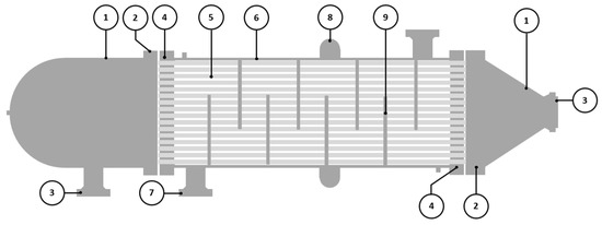
Figure 1.
Schematic drawing of BEM TEMA-type shell and tube heat exchanger.

Table 1.
BEM TEMA-type shell and tube heat exchanger parts.
This heat exchanger used two types of materials: the shell material was carbon steel, and the tube and tube sheet material was 2205 duplex stainless steel (UNS S31803). A hypochlorite solution at two ppm by volume was injected into the running pump caisson to prevent marine growth in the cooling water; a flow of 15 to 20 US gallons per minute of hypochlorite solution should be maintained for any running pump. Although 2205 DSS offers high strength, good general corrosion resistance, high resistance to chloride-induced SCC, and high resistance to pitting attack in chloride environments, e.g., seawater [5], the heat exchanger in this study experienced some material degradation after 28 months of use; 102 out of 270 tubes failed, 26 tubes leaked and were plugged on both sides, and scale plugged 76 tubes. This study conducted a failure analysis and found the root cause of the heat exchanger failure.
The failure investigation was conducted on two heat exchangers, one on the platform and one laid down in the warehouse, due to some defects. Both heat exchangers have been operating for 28 months. The main steps performed to determine the root cause of the observed damage are shown in Figure 2. Visual inspections were conducted on both heat exchangers, including the tube-and-tube-sheet-welded section, and plugged and unplugged tubes. The chemical composition of the tube and tube sheet material was examined using a optical emission spectroscopy (Hilger E-9 OA701, Margate, UK) to confirm the alloy grade. The hardness test was conducted on the tube and tube sheet material using a Vickers microhardness tester (ZwickRoell ZHV30, Ulm, Germany) with a load of 200 grams to confirm the alloy grade [26]. The chloride content, water salinity, sulfate content, and total dissolved solids of the cooling medium were determined by conducting a seawater examination. Tube deposit scale examination was performed by using energy dispersive spectrometry (EDS) (JEOL JSM 6510 LA, Tokyo, Japan) and X-ray diffraction (Rigaku Smart Lab, Tokyo, Japan). A fractography examination was conducted using a scanning electron microscope (JEOL JSM 6510 LA, Tokyo, Japan) to observe the corrosion appearance. The microstructure of the tubes was examined by cutting some samples at the corroded region and mounting them into a cold-setting resin. The samples were ground with 400, 600, 800, 1000, 1200, 1500, and 2000 grit SiC abrasive paper and polished with diamond paste to 0.25 µm. The polished samples were swabbed with Beraha etchant for 15 seconds and observed under an optical microscope [27].
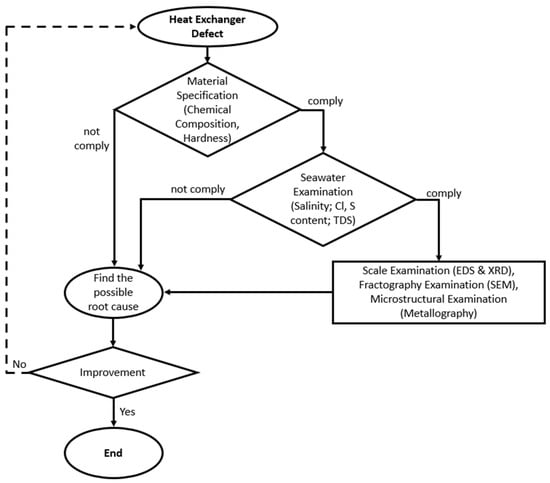
Figure 2.
Flowchart of the failure investigation.
3. Results
3.1. Visual Examination
Visual examinations were conducted on two heat exchangers. Figure 3a is the photograph of the heat exchanger on the platform; defects were found on the welded section between the tube and tube sheet (the circled section shows the defects of the tube sheet under the gasket area); further examination of this defect is shown in Figure 4a,b. The tube sheet of the heat exchanger at the warehouse (Figure 3b) contained some leaked tubes. The circled section shows that some leaked tubes were plugged and weld-overlayed. For further examination, the heat exchanger at the warehouse was cut into several sections, including the tube sheet and gasket interface, tube sheet inlet sections, and the tube itself.
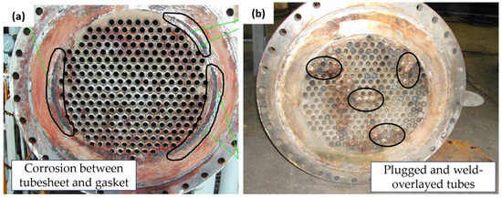
Figure 3.
Failed heat exchangers’ appearance: (a) tube sheet of heat exchanger on the platform; (b) tube sheet of heat exchanger at the warehouse.
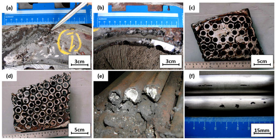
Figure 4.
(a,b) Tube sheet and gasket interface; (c,d) tube sheet inlet sections; (e) lateral section of tubes; (f) tube surface condition.
Figure 4a,b show the further examination of Figure 3a. Pitting defects under the gasket can be seen at the tube sheet interfaces; this defective surface was examined further to determine the root cause of pitting defects. Figure 4c,d show the pieces of the seawater inlet tube sheet. As practical information, when corrosion was found on the tube sheet, a plug was applied to the corroded tube, and the tube sheet was repaired by overlaying the tube sheet. Figure 4e shows a cut and plugged tube on the outlet side; white scale deposits were observed inside the tubes. Two pieces of the plugged tubes were cut for laboratory examinations to examine the crack locations. The outer surface of the tube was cleaned with fine emery paper and observed visually with a dye penetrant and magnifying glass. There was no crack observed on the outer surface of the tube. Some shallow pitting was observed on the outer surface close to the outlet. However, this pitting started from the outer surface, and some could be removed with emery paper. Figure 4f shows the defective tube’s surface appearance. For further examination, the tube was cut longitudinally and the appearance of the tube’s inner surface conditions was assessed; this examination was conducted on the plugged tube, an unplugged tube, and a standard tube without defects.
The cross-section of the tube with no defects in Figure 5a shows that a weld overlay joined the tube and tube sheet; the overlay of the tube sheet protected it from corrosion and sealed the possible gap between the tube and tube sheet. No defects like corrosion or leak was observed in this tube, and the weld overlay sealed the gap between the tube and tube sheet well. Figure 5b,c are macro photographs of the plugged tube, and the tube was initially cold expanded on the tube sheet. Corrosion occurred on the tube sheet and has been repaired by weld overlay. Figure 5d,e are pictures of the plugged tube’s inner surface. Heavy deposits under the plug were observed, and some deposits along the tube indicated the presence of a biofilm that may promote microbiologically induced corrosion. Figure 5f is the cross-section of the unplugged tube. Heavy deposits on the entrance side were observed, and some deposits along the tube indicated the presence of a biofilm that may promote microbiologically induced corrosion.
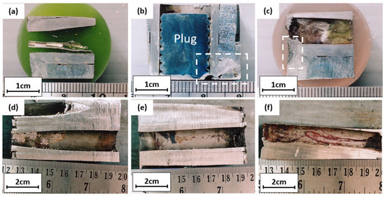
Figure 5.
Longitudinal cross-section of (a) tube without defects; (b–e) plugged tube; (f) unplugged tube.
3.2. Chemical Composition
The chemical composition of the tube and tube sheet material was examined by optical emission spectrometry. The results are shown in Table 2.
Table 2.
Chemical composition of tube and tube sheet (weight %), data from [28].
Based on optical emission spectrometry results, the tube and tube sheet materials comply with duplex stainless steel ASTM A-790/UNS S31803. The mechanical properties of UNS S31803 are shown in Table 3.
Table 3.
Mechanical properties of UNS S31803, data from [28].
3.3. Hardness Test
Besides chemical composition, a hardness test was conducted using a Vickers microhardness tester (ZwickRoell, Ulm, Germany) with a load of 200 grams for material confirmation purposes. The survey was conducted on tube and tube sheet materials, and the hardness distribution is shown in Table 4.
Table 4.
Tube and tube sheet hardness (VHN), data from [28].
The hardness of the tube and tube sheet is below the ASTM A-790/UNS S31803 specification and was widely scattered due to the torch cutting and the heating effect, which may cause a significant variation in the materials’ hardness.
3.4. Seawater Examination
A seawater examination was conducted to determine the seawater’s salinity, chloride, sulfate, and total dissolved solids. Samples were taken from the discharge cooler and the discharge cooling pump. The analysis results are shown in Table 5.
Table 5.
Seawater examination result.
Seawater salinity can be calculated as [29]:
S (‰) = 1.80655 Cl (‰)
Based on the equation, the salinity was 33.4%, and the increase in salinity increased the rate of calcium carbonate precipitation [30]. The chloride content was typical for seawater (around 19,000 mg/L), and the sulfate content was also considered normal (around 2600 mg/L) [29]. The total dissolved solids were considerably high (32 g/L) and will contribute to the formation of deposits and scale in stagnant conditions [31].
3.5. Scale Examination
The tube deposit in Figure 3e was examined using SEM and EDS. Figure 6a is the SEM macrograph of the tube scale deposit; the particle size was very fine, indicating that it was formed through a chemical reaction. Figure 6b shows the results from energy dispersive spectrometry of the tube deposit, with a predominance of calcium, magnesium, and oxygen elements. This examination result were further examined using an XRD analysis, as illustrated in Figure 7.

Figure 6.
(a) SEM examination of tube scale deposit (b) EDS results of tube scale deposit.
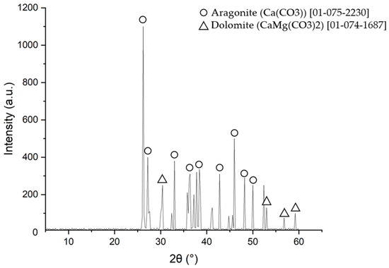
Figure 7.
XRD examination of tube scale deposit.
Based on the XRD examination results, the majority of the tube scale was aragonite (CaCO3) and dolomite (CaMg(CO3)2). The X-ray diffraction results confirmed the energy dispersive spectrometry data, which showed that calcium, magnesium, and oxygen were the main components in the tube deposit. According to the shape of the deposit and its compounds, this scale was formed by microbiologically induced calcium carbonate precipitation (MICP) [31,32,33]. The detailed mechanism of scale formation and the composition of the scale will be discussed further in the discussion section.
3.6. Fractography Examination
The surface of the tube sheet in Figure 4a,b was cleaned with Clark solution before the examination but the dirt on the surface could not be entirely removed by the Clark solution. The SEM micrograph of the tube sheet’s defective surface shown in Figure 8a revealed traces of barnacles. The pitting present indicates the effect of a microbiological attack on the surface; bacterial activity may change the structure and properties of the passivation film on the stainless steel, affecting pitting initiation and growth. Generally, compact microbial biofilms can act as diffusion barriers for reactants such as oxygen, aggressive anions, and cations [34,35,36,37]. Figure 8b is the scanning electron macrograph of another defective surface. A detailed examination of the defective surface could not be performed because a permanent deposit covered the surface.
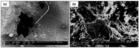
Figure 8.
SEM examination of tube sheet (a) pitting appearance (b) defective surface.
3.7. Microstructural Examination
Figure 9a represents the tube base material with no defects, and Figure 9b shows the base material microstructure of the tube sheet. The corroded surface of the tube sheet from Figure 4a was examined using an optical micrograph. Figure 9a,b show that corrosion attacks occurred preferentially along the austenite grains and there was no attack on the ferrite grain. A preferential attack on the austenite grain of the weld metal phenomenon was observed during the crevice corrosion test. According to prior studies, preferential dissolution occurs at all morphologies of austenitic phases: grain boundary (GBA), Widmanstätten (WA), and intragranular (IGA) [38,39,40]. The corrosion attack on the tube sheet was caused by crevice corrosion between the surface deposit (bacteria product) on the tube sheet surface and the substrate.
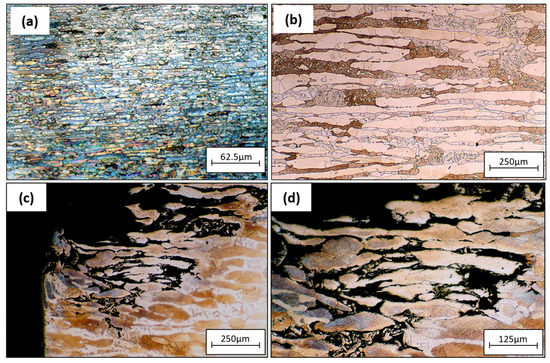
Figure 9.
Optical micrographs of (a) tube base material without defects, (b) tube sheet base material, (c,d) corroded section of tube sheet 3(a).
Figure 10 is an optical micrograph of the corroded tube sheet at the other location. The type of attack was different from that of Figure 9. The corrosion attack occurred under a deposit produced by bacteria. Previous fractography data indicated that the corrosion at this site was caused by micro/macro-fouling. However, the corrosion occurred under the gasket; therefore, macro/micro-fouling was formed and attacked the tube sheet surface. According to Figure 10, the corrosion mechanism was crevice corrosion between the substrate and surface deposit that was enhanced by microbiologically induced corrosion (MIC) [39,40,41].
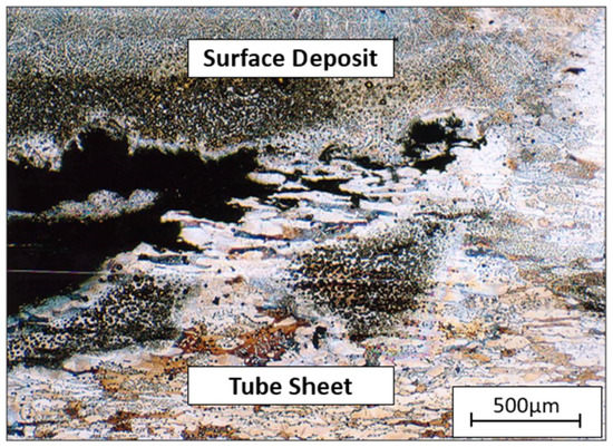
Figure 10.
Optical micrograph of a corroded section of tube sheet 3(b).
Figure 11 is an optical micrograph of the unplugged tube. Corrosion occurred on the inner surface of the tube, and the austenite grains were attacked by crevice corrosion [39,40]. Corrosion also occurred on the tube sheet overlay.
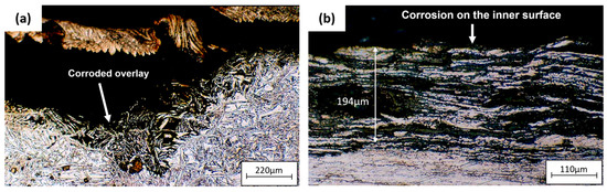
Figure 11.
Optical micrographs of (a) corrosion on tube sheet overlay of the unplugged tube, (b) corrosion on the inner surface of the unplugged tube.
Figure 12 is an optical micrograph of a plugged tube. Figure 12a shows the inner surface of the tube attacked by corrosion, with the depth of the austenite grains attacked being 141 μm. Figure 12b shows the occurrence of corrosion in the crevice between the plug and the tube. The tube–sheet overlay was also attacked by corrosion (Figure 12c).
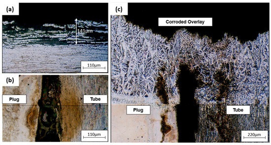
Figure 12.
Optical micrographs of (a) corrosion on the inner surface of the plugged tube, (b) tube and plug corroded interface, (c) corrosion on tube sheet overlay of the plugged tube.
4. Discussion
The tube and tube sheet materials are made of duplex stainless steel UNS 31803. Corrosion of the tube sheet may have been caused by galvanic corrosion between the gasket and the tube sheet or between the tube sheet and the carbon steel shell, crevice corrosion, or microbiologically induced corrosion. The probability of each corrosion mechanism will be discussed further in Section 4.1, Section 4.2 and Section 4.3.
4.1. Galvanic Corrosion
Galvanic corrosion occurs when a metal or alloy is electrically coupled to another metal or conducting non-metal in the same electrolyte. During galvanic coupling, corrosion of the less corrosion-resistant metal increases while corrosion of the more corrosion-resistant metal decreases. The driving force for corrosion or current flow is the potential developed between dissimilar metals. Possible galvanic coupling could occur between the tube sheet and conductive gasket and between the tube sheet and carbon steel shell. The type of gasket material is unknown, so the possibility of galvanic coupling cannot be determined [42].
There are two reasons galvanic coupling did not cause tube sheet corrosion: First, when the galvanic coupling formed between the tube sheet material and carbon steel shell, carbon steel would corrode because it is less noble than duplex stainless steel. Corrosion occurred in the tube sheet but not in the shell material. Second, most galvanic corrosion attacks are similar to general corrosion without surface deposits. If the attack is pitting, the pitted surface will be shiny, and there will be no surface deposits.
4.2. Crevice Corrosion
Small pits can form on the steel surface under specific conditions, particularly those involving chlorides (such as sodium chloride in seawater) and exacerbated by elevated temperatures. Depending on both the environment and the steel itself, these small pits may continue to grow, and if they do, they can lead to perforation, while most of the steel surface may still be unaffected. Crevice corrosion can be considered a particular case of pitting corrosion, where the initial pit is provided by an external feature, such as a narrow opening or spaces (gaps) between metal-to-metal or nonmetal-to-metal components. Similarly, unintentional crevices such as cracks, rough surfaces, sheared edges, and other metallurgical defects can be sites for corrosion initiation. Crevice attack also occurs under deposits and biofouling growth attached to the metal surface [43].
Stainless steel groups, including duplex stainless steel, a passive alloy, are more prone to crevice attack in seawater than materials that exhibit more active behavior. The pitting resistance of duplex stainless steel is defined as resistance to localized corrosion attack and is expressed as the Pitting Resistance Equivalent Number (PREN) [44]:
PREN = Cr + 3.3 (Mo + 0.5 W) + 16 N
Using PREN as a reference, several duplex stainless steels with different alloy contents will have different pitting resistance, as shown in Table 6.
Table 6.
Pitting resistance of some types of duplex stainless steel data from [28,45].
According to Table 6, UNS 31803 has a lower pitting resistance than the other grades. The pitting resistance of duplex stainless steel in seawater can be expressed as the critical pitting temperature (CPT), below which pitting will not occur. Similar to pitting corrosion, the susceptibility of duplex stainless steel to crevice corrosion is expressed as the critical crevice temperature (CCT). Figure 13 shows the critical pitting and crevice temperatures in a 6% ferric chloride solution for 24 hours of some types of stainless steel [45].
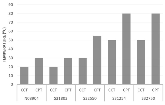
Figure 13.
Critical pitting temperature (CPT) and critical crevice temperature (CCT) of some alloys reproduced from [45].
The duplex stainless steel type with the lowest pitting and crevice corrosion resistance is UNS S31803. The critical crevice temperature of UNS S31803 is about 20 °C; above this, crevice corrosion will occur. The severity and rate of crevice corrosion will depend on the crevice’s geometry and the seawater quality. Crevice corrosion of the tube–sheet joint is likely to occur under the gasket and between the tube and tube–sheet joint. Crevice corrosion under the gasket is a consequence that cannot be prevented for seawater service unless a better design and better materials are selected. The expanded joint type is not recommended for tubes and tube sheets used in seawater service, as the possibility of crevice formation is much higher than that of a welded joint. Applying an overlay on the tube–sheet surface is acceptable, but the overlay material should be selected to avoid crevice corrosion. The current overlay was insufficient to prevent crevice corrosion, as some parts were attacked. The surface quality of the overlay should also be considered because a rough surface will create tiny crevices that can harm the surface.
4.3. Microbially Induced Corrosion
In certain circumstances, microbial activity can influence the corrosion process and typically involves microbes that metabolize sulfur compounds, producing an aggressive, acidic, hydrogen sulfide-containing localized environment [46]. When stainless steel is in contact with natural seawater, a biofilm will grow on the steel surface. Crevice corrosion may also occur because of localized deposits or differential aeration cells caused by slime-forming bacteria. The aggregation and inhomogeneity of biofilms causes localized differences in the chemical and electrochemical environments at the interface. These gradients in pH, sulfide, chloride, or dissolved oxygen are crucial in the beginning and hastening of concentration cell and galvanic corrosion. Corrosion due to microbial activity takes the form of a pitting attack. Since UNS S31803 is prone to crevice attack, accumulating microbes in the crevice region will promote pitting corrosion under deposit. Localized deposits cause tube corrosion on the inner surface under the biofilm [32].
The XRD scale examination showed calcium carbonate (CaCO3) as the tube deposit. Calcium carbonate sediments are prevalent in the ocean. The origin of calcium carbonate is the result of the following chemical reactions [31,33,47]:
CO2 + OH− → HCO3−
OH− + HCO3− → H2O + CO3−2
CO3−2 + Ca+2 → CaCO3
OH− + HCO3− → H2O + CO3−2
CO3−2 + Ca+2 → CaCO3
In the form of Ca+2 ion, calcium is one of the major inorganic positive ions (cations) in saltwater and freshwater. It can originate from the dissociation of salts, such as calcium chloride or calcium sulfate in water [31,33].
CaCl2 (s) → Ca+2 (aq) + 2 Cl− (aq)
CaSO4 (s) → Ca+2 (aq) + 2 SO4−2 (aq)
CaSO4 (s) → Ca+2 (aq) + 2 SO4−2 (aq)
Most calcium in surface water comes from streams flowing over limestone (CaCO3), gypsum (CaSO4·2H2O), and other calcium-containing rocks and minerals. Calcium carbonate is relatively insoluble in water but dissolves more readily in water containing significant levels of dissolved carbon dioxide [47]. Tube deposits were found only on plugged tubes. The tube deposit came from the solid particles in seawater, as the total dissolved solid content was high. If the outlet ends were not plugged, seawater could enter the plugged tube from the outlet side. This way, the seawater will remain in the plugged tube, and the solid or colloidal particles will be deposited inside the plugged tube. Solid particles will be accumulated due to the low velocity and almost stagnant seawater inside the plugged tube.
5. Conclusions
UNS S31803 shell and tube heat exchangers that were cooled by seawater experienced corrosion caused by crevice corrosion enhanced by microbiologically induced corrosion (MIC). The crevice was between the bacteria’s metabolic products and the substrate material, as confirmed by the scale’s shape, size, and its compounds that contained CaCO3. This scale was formed by microbiologically induced calcium carbonate precipitation (MICP) [31,33]. The microstructural examination revealed that corrosion attack occurred preferentially along the austenite grains; this phenomenon is common in duplex stainless steel, which typically fails due to crevice corrosion [39,40]. The use of materials that are inappropriate for the heat exchangers’ seawater cooling medium conditions is the leading/root cause of this issue.
Some efforts to prevent similar crevice corrosion enhanced by microbiologically induced corrosion (MIC) in heat exchangers (discharge coolers) include upgrading materials to ones that can resist crevice corrosion in seawater at the operating temperature, which can be determined by the critical pitting temperature (CPT) and critical crevice temperature (CCT). In the design and manufacturing aspects, several efforts should be made to avoid crevice corrosion, including designing and fabricating to avoid trapped and pooled liquid; designing and fabricating to avoid crevices; using a weld joint between the tube and tube sheet instead of a cold expanded joint; preparing surfaces to the best possible finish (mirror finish resists pitting best); removing all contaminants and weld scale; welding using the correct consumables and practices; and inspecting to check for inadvertent crevices. The application of an overlay on the tube–sheet surface is an accepted practice. The current overlay was insufficient to prevent crevice corrosion, as some parts were attacked. The surface quality of the overlay should also be considered because a rough surface will create tiny crevices that can harm the surface.
Author Contributions
Formal analysis, A.S.; investigation, T.A.; writing—review and editing, H.A. All authors have read and agreed to the published version of the manuscript.
Funding
This research received no external funding.
Data Availability Statement
The data presented in this study are available on request from the corresponding author.
Acknowledgments
We acknowledged the contribution of an Oil and Gas Company in Indonesia in providing the material for this work. Any findings or conclusions stated in this paper are of the Authors and do not represent the Company in any capacity.
Conflicts of Interest
The authors declare no conflict of interest.
References
- Schweitzer, P.A. Fundamentals of Metallic Corrosion: Atmospheric and Media Corrosion of Metals; CRC Press: Boca Raton, FL, USA, 2006. [Google Scholar]
- Shifler, D.A. La Que’s Handbook on Marine Corrosion; Wiley & Sons: Hoboken, NJ, USA, 2021. [Google Scholar]
- Balaji, C.; Srinivasan, B.; Gedupudi, S. Chapter 7—Heat Exchangers. In Heat Transfer Engineering; Balaji, C., Srinivasan, B., Gedupudi, S., Eds.; Academic Press: Cambridge, MA, USA, 2021; pp. 199–231. ISBN 978-0-12-818503-2. [Google Scholar]
- Morales, M.; Chimenos, J.M.; Fernández, A.I.; Segarra, M. Materials Selection for Superheater Tubes in Municipal Solid Waste Incineration Plants. J. Mater. Eng. Perform. 2014, 23, 3207–3214. [Google Scholar] [CrossRef]
- Moura, V.S.; Lima, L.D.; Pardal, J.M.; Kina, A.Y.; Corte, R.R.A.; Tavares, S.S.M. Influence of Microstructure on the Corrosion Resistance of the Duplex Stainless Steel UNS S31803. Mater. Charact. 2008, 59, 1127–1132. [Google Scholar] [CrossRef]
- Farrer, J.C.M. The Alloy Tree, A Guide to Low-Alloy Steels, Stainless Steels and Nickel-Base Alloys; CRC Press: Boca Raton, FL, USA, 2004. [Google Scholar]
- Ravindranath, K.; Tanoli, N.; Gopal, H. Failure Investigation of Brass Heat Exchanger Tube. Eng. Fail. Anal. 2012, 26, 332–336. [Google Scholar] [CrossRef]
- Azevedo, C.R.F.; Alves, G.S. Failure Analysis of a Heat-Exchanger Serpentine. Eng. Fail. Anal. 2005, 12, 193–200. [Google Scholar] [CrossRef]
- Jones, D.R.H. Creep Failures of Overheated Boiler, Superheater and Reformer Tubes. Eng. Fail. Anal. 2004, 11, 873–893. [Google Scholar] [CrossRef]
- Psyllaki, P.P.; Pantazopoulos, G.; Lefakis, H. Metallurgical Evaluation of Creep-Failed Superheater Tubes. Eng. Fail. Anal. 2009, 16, 1420–1431. [Google Scholar] [CrossRef]
- Kain, V.; Chandra, K.; Sharma, B.P. Failure of Carbon Steel Tubes in a Fluidized Bed Combustor. Eng. Fail. Anal. 2008, 15, 182–187. [Google Scholar] [CrossRef]
- Al Arada, M.; Al Otaibi, M. Evaluation of High Temperature Hydrogen Attack Effect on Carbon Steel—0.5 Mo Heat Exchanger. In Proceedings of the NACE—International Corrosion Conference Series, San Antonio, TX, USA, 9–13 March 2014. [Google Scholar]
- Otegui, J.L.; Fazzini, P.G. Failure Analysis of Tube–Tubesheet Welds in Cracked Gas Heat Exchangers. Eng. Fail. Anal. 2004, 11, 903–913. [Google Scholar] [CrossRef]
- Corleto, C.R.; Argade, G.R. Failure Analysis of Dissimilar Weld in Heat Exchanger. Case Stud. Eng. Fail. Anal. 2017, 9, 27–34. [Google Scholar] [CrossRef]
- Liu, L.; Ding, N.; Shi, J.; Xu, N.; Guo, W.; Wu, C.M.L. Failure Analysis of Tube-to-Tubesheet Welded Joints in a Shell-Tube Heat Exchanger. Case Stud. Eng. Fail. Anal. 2016, 7, 32–40. [Google Scholar] [CrossRef]
- Goyder, H.G.D. Flow-Induced Vibration in Heat Exchangers. Chem. Eng. Res. Des. 2002, 80, 226–232. [Google Scholar] [CrossRef]
- Kuźnicka, B. Erosion-Corrosion of Heat Exchanger Tubes. Eng. Fail. Anal. 2009, 16, 2382–2387. [Google Scholar] [CrossRef]
- Gong, Y.; Yang, Z.-G.; Yuan, J.-Z. Failure Analysis of Leakage on Titanium Tubes within Heat Exchangers in a Nuclear Power Plant. Part II: Mechanical Degradation. Mater. Corros. 2012, 63, 18–28. [Google Scholar] [CrossRef]
- Xu, S.; Wang, C.; Wang, W. Failure Analysis of Stress Corrosion Cracking in Heat Exchanger Tubes during Start-up Operation. Eng. Fail. Anal. 2015, 51, 1–8. [Google Scholar] [CrossRef]
- Adnyana, D.N. Failure Analysis of Stainless Steel Heat Exchanger Tubes in a Petrochemical Plant. J. Fail. Anal. Prev. 2018, 18, 413–422. [Google Scholar] [CrossRef]
- Khodamorad, S.H.; Alinezhad, N.; Fatmehsari, D.H.; Ghahtan, K. Stress Corrosion Cracking in Type.316 Plates of a Heat Exchanger. Case Stud. Eng. Fail. Anal. 2016, 5, 59–66. [Google Scholar] [CrossRef]
- Al-Nabulsi, K.M.; Rizk, T.Y.; Al-Abbas, F.M.; Dias, O.C. Sea Water Cooler Tubes Corrosion and Leaks Due to Microbiologically Induced Corrosion. In Proceedings of the NACE—International Corrosion Conference Series, Vancouver, BC, Canada, 6–10 March 2016; Volume 1, pp. 141–148. [Google Scholar]
- Abraham, G.J.; Kain, V.; Dey, G.K. MIC Failure of Cupronickel Condenser Tube in Fresh Water Application. Eng. Fail. Anal. 2009, 16, 934–943. [Google Scholar] [CrossRef]
- Huttunen-Saarivirta, E.; Honkanen, M.; Lepistö, T.; Kuokkala, V.-T.; Koivisto, L.; Berg, C.-G. Microbiologically Influenced Corrosion (MIC) in Stainless Steel Heat Exchanger. Appl. Surf. Sci. 2012, 258, 6512–6526. [Google Scholar] [CrossRef]
- Sharma, P. Microbiological-Influenced Corrosion Failure of a Heat Exchanger Tube of a Fertilizer Plant. J. Fail. Anal. Prev. 2014, 14, 314–317. [Google Scholar] [CrossRef]
- ASTM E384-22; Standard Test Method for Microindentation Hardness of Materials. ASTM International: West Conshohocken, PA, USA, 2022. [CrossRef]
- ASTM E3-11(2017); Standard Guide for Preparation of Metallographic Specimens. ASTM International: West Conshohocken, PA, USA, 2017. [CrossRef]
- ASTM A790/A790M-23; Standard Specification For Seamless And Welded Ferritic/Austenitic Stainless Steel Pipe. ASTM International: West Conshohocken, PA, USA, 2023. [CrossRef]
- Millero, F.J.; Huang, F. The Density of Seawater as a Function of Salinity (5 to 70 g Kg−1) and Temperature (273.15 to 363.15 K). Ocean. Sci. 2009, 5, 91–100. [Google Scholar] [CrossRef]
- Mortensen, B.M.; Haber, M.J.; Dejong, J.T.; Caslake, L.F.; Nelson, D.C. Effects of Environmental Factors on Microbial Induced Calcium Carbonate Precipitation. J. Appl. Microbiol. 2011, 111, 338–349. [Google Scholar] [CrossRef]
- Liu, Y.; Ali, A.; Su, J.-F.; Li, K.; Hu, R.-Z.; Wang, Z. Microbial-Induced Calcium Carbonate Precipitation: Influencing Factors, Nucleation Pathways, and Application in Waste Water Remediation. Sci. Total Environ. 2023, 860, 160439. [Google Scholar] [CrossRef]
- Chen, X.; Xiao, C.; Wang, X.; Yang, J.; He, C. Corrosion Behaviors of 2205 Duplex Stainless Steel in Biotic and Abiotic NaCl Solutions. Constr. Build. Mater. 2022, 342, 127699. [Google Scholar] [CrossRef]
- Lin, W.; Gao, Y.; Lin, W.; Zhuo, Z.; Wu, W.; Cheng, X. Seawater-Based Bio-Cementation of Natural Sea Sand via Microbially Induced Carbonate Precipitation. Environ. Technol. Innov. 2023, 29, 103010. [Google Scholar] [CrossRef]
- Huttunen-Saarivirta, E.; Rajala, P.; Marja-aho, M.; Maukonen, J.; Sohlberg, E.; Carpén, L. Ennoblement, Corrosion, and Biofouling in Brackish Seawater: Comparison between Six Stainless Steel Grades. Bioelectrochemistry 2018, 120, 27–42. [Google Scholar] [CrossRef] [PubMed]
- Yang, X.; Shao, J.; Liu, Z.; Zhang, D.; Cui, L.; Du, C.; Li, X. Stress-Assisted Microbiologically Influenced Corrosion Mechanism of 2205 Duplex Stainless Steel Caused by Sulfate-Reducing Bacteria. Corros. Sci. 2020, 173, 108746. [Google Scholar] [CrossRef]
- Cui, L.Y.; Liu, Z.Y.; Xu, D.K.; Hu, P.; Shao, J.M.; Du, C.W.; Li, X.G. The Study of Microbiologically Influenced Corrosion of 2205 Duplex Stainless Steel Based on High-Resolution Characterization. Corros. Sci. 2020, 174, 108842. [Google Scholar] [CrossRef]
- Xu, C.; Zhang, Y.; Cheng, G.; Zhu, W. Pitting Corrosion Behavior of 316L Stainless Steel in the Media of Sulphate-Reducing and Iron-Oxidizing Bacteria. Mater. Charact. 2008, 59, 245–255. [Google Scholar] [CrossRef]
- Aoki, S. Preferential Dissolution Mechanism of α or γ Phase in Crevice Corrosion of Duplex Stainless Steels. Zair. Kankyo/Corros. Eng. 2016, 65, 45–50. [Google Scholar] [CrossRef]
- Azzam, M.; Khalifa, W. Investigation of Duplex Stainless Steel Flow Line Failure. Eng. Fail. Anal. 2023, 143, 106935. [Google Scholar] [CrossRef]
- Nuñez de la Rosa, Y.E.; Calabokis, O.P.; Pena Uris, G.M.; Borges, P.C. Pitting and Crevice Corrosion Behavior of the Duplex Stainless Steel UNS S32205 Welded by Using the GTAW Process. Mater. Res. 2022, 25, e20220179. [Google Scholar] [CrossRef]
- Machuca, L.L.; Bailey, S.I.; Gubner, R.; Watkin, E.L.J.; Ginige, M.P.; Kaksonen, A.H.; Heidersbach, K. Effect of Oxygen and Biofilms on Crevice Corrosion of UNS S31803 and UNS N08825 in Natural Seawater. Corros. Sci. 2013, 67, 242–255. [Google Scholar] [CrossRef]
- Revie, R.W. Uhlig’s Corrosion Handbook, 3rd ed.; John Wiley & Sons: Hoboken, NJ, USA, 2011. [Google Scholar]
- Blackwood, D.J.; Lim, C.S.; Teo, S.L.M.; Hu, X.; Pang, J. Macrofouling Induced Localized Corrosion of Stainless Steel in Singapore Seawater. Corros. Sci. 2017, 129, 152–160. [Google Scholar] [CrossRef]
- Papavinasam, S. Chapter 6—Modeling—Internal Corrosion. In Corrosion Control in the Oil and Gas Industry; Papavinasam, S., Ed.; Gulf Professional Publishing: Boston, MA, USA, 2014; pp. 301–360. ISBN 978-0-12-397022-0. [Google Scholar]
- Gunn, R.N. 1—Developments, Grades and Specifications. In Duplex Stainless Steels; Gunn, R.N., Ed.; Woodhead Publishing: Cambridge, UK, 1997; pp. 1–13. ISBN 978-1-85573-318-3. [Google Scholar]
- Makhlouf, A.S.H.; Botello, M.A. Chapter 1—Failure of the Metallic Structures Due to Microbiologically Induced Corrosion and the Techniques for Protection. In Handbook of Materials Failure Analysis; Makhlouf, A.S.H., Aliofkhazraei, M., Eds.; Butterworth-Heinemann: Oxford, UK, 2018; pp. 1–18. ISBN 978-0-08-101928-3. [Google Scholar]
- Schütze, M. Corrosion Books: Handbook of Corrosion Engineering. By Pierre R. Roberge—Materials and Corrosion 4/2002. Mater. Corros. 2002, 53, 284. [Google Scholar] [CrossRef]


Disclaimer/Publisher’s Note: The statements, opinions and data contained in all publications are solely those of the individual author(s) and contributor(s) and not of MDPI and/or the editor(s). MDPI and/or the editor(s) disclaim responsibility for any injury to people or property resulting from any ideas, methods, instructions or products referred to in the content. |
© 2023 by the authors. Licensee MDPI, Basel, Switzerland. This article is an open access article distributed under the terms and conditions of the Creative Commons Attribution (CC BY) license (https://creativecommons.org/licenses/by/4.0/).